
Single-site cobalt catalyst embedded in a covalent triazine-based framework (CTF) for photocatalytic CO2 reduction†
Anupam
Jana
a,
Arijit
Maity
a,
Abhimanyu
Sarkar
a,
Bibhutibhushan
Show
 a,
Preeti A.
Bhobe
b and
Asamanjoy
Bhunia
*a
a,
Preeti A.
Bhobe
b and
Asamanjoy
Bhunia
*a
aDepartment of Chemistry, Inorganic Chemistry Section, Jadavpur University, Kolkata 700032, India. E-mail: abhunia.chemistry@jadavpuruniversity.in
bDepartment of Physics, Indian Institute of Technology Indore, Indore 453552, Madhya Pradesh, India
First published on 16th January 2024
Abstract
Transforming CO2 into carbonaceous fuels using photocatalysts is an attractive approach to address both the energy crisis and environmental issues simultaneously. However, the task of fabricating catalysts with exceptional photoreduction activity presents significant challenges in the field. Recently, cobalt-coordinated covalent organic frameworks (COFs) have drawn significant attention in the domain of CO2 photoreduction to CO owing to their notable electron affinity and carefully designed structure. In context to this, herein, a series of metal-loaded covalent triazine-based framework (CTF) photocatalysts have been prepared, where single Co2+ sites have been incorporated through a simple deposition method. The obtained Co-embedded CTF exhibited enhanced photocatalytic CO2 conversion to CO, which generates 1515 μmol CO, which is 37-fold more than that exhibited by pristine CTF-TPE (40 μmol) during the 2 h photocatalytic run. Furthermore, studies of EXAFS and XPS have been performed to examine the presence of single Co2+ sites and their role in the high-efficiency rate of CO2 conversion to CO. In addition, a plausible mechanism has been proposed for photocatalytic CO2 reduction through our experimental studies. This study paves the path for developing new catalysts of superior performance in the realm of CTF-based CO2 photoreduction.
Introduction
The exponential growth in the world's population, industrialization, and urbanization leads to the overconsumption of the world's energy. Unfortunately, the majority of the present energy sources rely on non-renewable resources such as fossil fuels (e.g., coal, gas, oil, etc.). This over-exploitation of fossil fuels not only causes the depletion of natural resources but simultaneously leads to the excessive emission of CO2 in the atmosphere, which is a primary driver of unprecedented global warming and other subsequent climate changes on a global scale over the past few decades.1–3 This increase in CO2 concentration at an alarming rate in the Earth's atmosphere will impact the natural carbon cycle, which will subsequently pose a threat to the entire human civilization. Certainly, it is accurate to anticipate that the era of oil will come to a close well before the Earth exhausts its oil reserves. This is due to the limitations imposed by emission regulations on the use of fossil fuels. Thus, there is an urgent need for the development of innovative, sustainable, and renewable technologies for mitigating climate change and promoting a sustainable environment. One of the effective strategies is the sequential adsorption and utilization of CO2. In particular, the visible light-induced photocatalytic CO2 reduction represents a promising and viable pathway as it has the capability to transform CO2 into valuable chemicals such as CO, CH4, CH3OH, C2H5OH, etc. It addresses contemporary environmental concerns and the energy crisis. To date, numerous semiconductors such as CdS,4 TiO2,5 and C3N4![[thin space (1/6-em)]](https://www.rsc.org/images/entities/char_2009.gif) 6 have been utilized in the realm of photocatalytic carbon dioxide reduction. However, these materials have yet to demonstrate their efficiency as photocatalysts for CO2 reduction, attributed to their manifestation of inadequate production yields and reaction product selectivity. This limited production and selectivity of products is attributed to the high recombination rate of photogenerated electron–hole pairs as well as the low adsorption capability of CO2 on the surface of these inorganic photocatalysts.7–9 Currently, various homogeneous10,11 and heterogeneous12–14 photocatalysts are being utilized in the photocatalytic CO2 reduction reaction. Even though homogeneous catalysts demonstrate high photocatalytic activity and selectivity in CO2 reduction,15,16 heterogeneous catalysts are preferred for large-scale industrial applications. The preference for heterogeneous catalysts arises from their diverse benefits such as preventing dimerization or aggregation, addressing solubility issues, enabling reuse, easy product separation, maintaining stability in extended operation and offering cost-effectiveness. Therefore, the pursuit of designing a novel photocatalyst for CO2 photoreduction to conquer these challenges holds paramount importance.
6 have been utilized in the realm of photocatalytic carbon dioxide reduction. However, these materials have yet to demonstrate their efficiency as photocatalysts for CO2 reduction, attributed to their manifestation of inadequate production yields and reaction product selectivity. This limited production and selectivity of products is attributed to the high recombination rate of photogenerated electron–hole pairs as well as the low adsorption capability of CO2 on the surface of these inorganic photocatalysts.7–9 Currently, various homogeneous10,11 and heterogeneous12–14 photocatalysts are being utilized in the photocatalytic CO2 reduction reaction. Even though homogeneous catalysts demonstrate high photocatalytic activity and selectivity in CO2 reduction,15,16 heterogeneous catalysts are preferred for large-scale industrial applications. The preference for heterogeneous catalysts arises from their diverse benefits such as preventing dimerization or aggregation, addressing solubility issues, enabling reuse, easy product separation, maintaining stability in extended operation and offering cost-effectiveness. Therefore, the pursuit of designing a novel photocatalyst for CO2 photoreduction to conquer these challenges holds paramount importance.
In recent years, the development of single-atom catalysts (SACs), that feature single metal atoms embedded into solid supports, has emerged as a promising strategy that has garnered significant attention in the field of heterogeneous catalysis.17,18 It combines the advantages of both heterogeneous and homogeneous catalysts and has shown great potential in the realm of CO2 reduction owing to uniform active sites, excellent atom utilization efficiency, and highly unsaturated coordination environment.19–22 Specifically, the distribution of individual atoms through coordination offers a sufficient number of unsaturated active sites. This arrangement facilitates the acceleration of charge separation and energy transfer, as well as the improved adsorption and activation of molecules. These characteristics prove advantageous to enhance the efficiency and selectivity of photocatalytic CO2 reduction.
The essential factor for the preparation of stable SACs is the interaction between the solid support and single metal sites. Most importantly, the interaction between the metal and support has a noteworthy influence on both the adsorption and activation of CO2 molecules, thereby enhancing the subsequent CO2 conversion.23,24 Therefore, it is crucial to design and develop robust solid supports to accommodate single metal atoms within the solid matrix by establishing strong interaction with the metal.25 Recently, there has been growing significant interest in covalent triazine-based framework (CTFs), a novel subclass of covalent organic frameworks (COFs) consisting of triazine molecular units. These frameworks have emerged as promising contenders for solar-driven photocatalysts due to their specific physicochemical characteristics, which include a tunable porous structure with extreme surface area, high nitrogen content, unique electronic properties, and superior chemical and thermal stabilities.21,26,27,28,29 The substantial surface area of CTFs along with their elevated N-content and Lewis basicity empowers them to capture a significant surplus of CO2 molecules activating them for subsequent transformation.30,31 In recent years, CTFs have garnered much attention as solid supports for anchoring single metal atoms through the N-atom of a triazine ring to prepare robust single atom photocatalysts (SACs).32 This incorporation of metal sites stands as a potent approach for enhancing photocatalytic activity by elevating active site numbers, facilitating efficient electron transfer into CTFs, and improving the separation efficiency of electron–hole pairs generated during photocatalysis.33
In our current investigation, a covalent triazine-based framework (CTF-TPE) has been synthesized from monomer tetra(4-cyanophenyl)ethylene under solvothermal conditions in the presence of CF3SO3H. The synthesized CTF has been used as a solid support for grafting the Co2+ atoms via coordination with the N-atom of the triazine moiety through a simple deposition method for photocatalytic CO2 reduction. The single Co2+ incorporated photocatalyst, CTF-TPE@Co-3 (3.1 wt% of Co), exhibits the highest photocatalytic efficiency and reaches CO evolution of 6616 μmol g−1 under a photocatalytic run of 7 hours, which is much higher than that exhibited by many earlier reported CTF-based photocatalysts (Table S4, ESI†). Additionally, we have unveiled the presence of single Co sites via spectroscopic evidence, elucidating their pivotal contribution to the enhancement of photocatalytic CO2 reduction. Furthermore, a plausible mechanism was explored for the enhancement of photocatalytic CO2 reduction. Our study deepens insight into the fabrication and mechanism of single atom embedded CTFs in the context of photocatalytic CO2 reduction.
Experimental section
Synthesis
To prepare CTF-TPE, tetra(4-cyanophenyl)ethylene (200 mg) was added directly into a mixture of DCM (1.23 mL) and TFMS (0.47 mL) in a clean vial, followed by sonication for 10 minutes. Next, for the solvothermal synthesis of CTF, we placed the resulting solution in a preheated oven at 50 °C for 24 h. The dark purple-colored product was quenched and washed with a mixed solvent of DCM and DMF (2:1 v/v). Finally, a yellow powder was obtained by filtration and washed with H2O (2 × 30 mL), THF (2 × 30 mL), DCM (2 × 30 mL), and acetone (2 × 30 mL), and the material was subsequently purified by Soxhlet extraction with acetone for 24 h. The resulting product was then dried under vacuum conditions. The yield of the final product was 85%.
Synthesis of CTF-TPE@Co
To deposit Co2+ on CTF-TPE, 25 mg of CTF-TPE was mixed with a specific amount of CoCl2 in 2.5 mL acetonitrile. Then 65 μL TEA was added to the mixture, which was subsequently stirred for 1 h. The mixture in a capped reaction vessel was placed in a CEM Discover single-mode microwave reactor and was heated to 80 °C for 120 min. After the microwave reaction, the resulting precipitate was recovered by centrifugation and washed twice with chloroform, methanol, and acetonitrile, respectively. Following a similar procedure, a series of CTF-TPE@Co-n (n = 1 to 4; where 1 = 0.150 μmol of Co loading per mg; similarly, 2 = 0.250 μmol mg−1, 3 = 0.400 μmol mg−1, and 4 = 0.700 μmol mg−1) with different cobalt loadings have been prepared to study the variation in photocatalytic CO2 reduction.Results and discussion
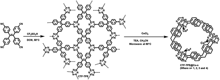
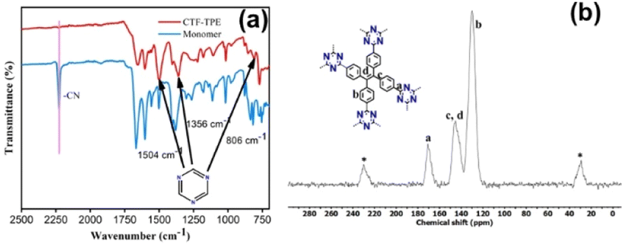
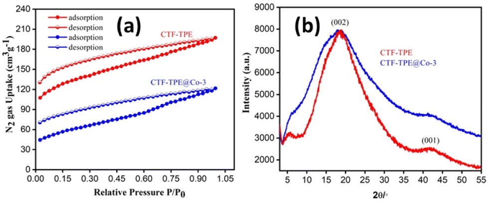
The polymerization of tetra(4-cyanophenyl)ethylene under solvothermal conditions in the presence of CF3SO3H resulted in the formation of CTF-TPE with a high yield (Scheme 1 and also in the Experimental section). The FT-IR measurements provided valuable insights into the trimerization reaction. Upon examining the infrared (IR) spectra depicted in Fig. 1a, it becomes apparent that a distinct and intense stretching band associated with the –CN group is absent at around 2226 cm−1, which indicates the successful trimerization reaction of the monomer tetra(4-cyanophenyl)ethylene. Moreover, the characteristic absorption bands at around 1504 cm−1 and 1356 cm−1 are attributed to the C–N stretching bands of the triazine units (Fig. 1a).34 Additionally, CTF-TPE exhibits a peak at around 806 cm−1, which is associated with the triazine moiety (Fig. 1a).35 The synthesized CTF was additionally characterized using solid-state 13C CP/MAS NMR spectroscopy, providing valuable insights into its structural composition (Fig. 1b). The obtained spectra displayed three prominent resonances appearing at approximately 170, 144, and 130 ppm, which can be assigned to the carbon atom of the triazine ring (N![[double bond, length as m-dash]](https://www.rsc.org/images/entities/char_e001.gif) C–N), ethylene carbon atom (–CC–), and aromatic carbon atoms, respectively. Remarkably, the absence of any peak corresponding to residual cyano end groups in the spectra confirms the complete trimerization reaction of all the monomers. The absence of residual cyano end groups further highlights the high conversion efficiency achieved during the trimerization process, indicating a successful transformation of the starting monomers into the desired CTF structure. This finding aligns perfectly with the results obtained from IR spectroscopy. The porosity of CTF-TPE was calculated by N2 adsorption study at 77 K. The calculated Brunauer–Emmett–Teller (BET) surface area and pore volume of the pristine CTF were found to be 434 m2 g−1 and 0.27 cm3 g−1, respectively (Fig. 2a and Table S2 in ESI†). Moreover, the assessment of the pore size in CTF-TPE was also conducted using the quenched solid density functional theory (QSDFT) slit/cylindrical pore model which exhibited a major pore at 0.4 nm with an additional pore at 0.8 and in the range of 1.2–1.5 nm (Fig. S5, ESI†).
C–N), ethylene carbon atom (–CC–), and aromatic carbon atoms, respectively. Remarkably, the absence of any peak corresponding to residual cyano end groups in the spectra confirms the complete trimerization reaction of all the monomers. The absence of residual cyano end groups further highlights the high conversion efficiency achieved during the trimerization process, indicating a successful transformation of the starting monomers into the desired CTF structure. This finding aligns perfectly with the results obtained from IR spectroscopy. The porosity of CTF-TPE was calculated by N2 adsorption study at 77 K. The calculated Brunauer–Emmett–Teller (BET) surface area and pore volume of the pristine CTF were found to be 434 m2 g−1 and 0.27 cm3 g−1, respectively (Fig. 2a and Table S2 in ESI†). Moreover, the assessment of the pore size in CTF-TPE was also conducted using the quenched solid density functional theory (QSDFT) slit/cylindrical pore model which exhibited a major pore at 0.4 nm with an additional pore at 0.8 and in the range of 1.2–1.5 nm (Fig. S5, ESI†).
 | ||
| Scheme 1 Synthesis of CTF-TPE and CTF-TPE@Co-n. | ||
 | ||
| Fig. 1 (a) IR spectra of the monomer and CTF-TPE. (b) Solid-state 13C CP/MAS NMR spectrum of CTF-TPE (* belongs to sidebands). | ||
 | ||
| Fig. 2 (a) N2 adsorption–desorption isotherm of CTF-TPE and CTF-TPE@Co-3 and (b) PXRD pattern of CTF-TPE and CTF-TPE@Co-3. | ||
A series of Co-modified CTF-TPE including CTF-TPE@Co-1, CTF-TPE@Co-2, CTF-TPE@Co-3, and CTF-TPE@Co-4 have been synthesized using CoCl2 in the presence of TEA and CH3CN via a simple deposition method as reported previously (Scheme 1 and also see in the Experimental section).25 The amount of cobalt (wt%) present in the synthesized CTF-TPE@Co-1 to-4 were calculated by ICP-AES, found to be 0.8%, 1.5%, 3.1%, and 5.9%, respectively (Table S3, ESI†). However, no change in IR spectra has been observed for different cobalt-loaded CTF-TPE materials (Fig. S1, ESI†) indicating the durability of the material. The thermal stability of both CTF-TPE and CTF-TPE@Co was assessed through thermogravimetric analysis (TGA), which indicated that these materials remained stable up to a temperature of 320 °C (Fig. S2, ESI†). The initial weight loss observed in both cases can be attributed to the removal of water molecules and certain guest solvent molecules from the pores of the materials. However, as the temperature exceeded 400 °C, a subsequent weight loss was observed, indicating the decomposition of the residual polymeric scaffold.36 However, among all these cobalt-loaded samples, CTF-TPE@Co-3 is interesting because of its high catalytic activity under optimum conditions. Hence, a detailed structural analysis of CTF-TPE@Co-3 has been performed.
As predicted, the BET surface area of CTF-TPE@Co-3, measured by N2-sorption at 77 K after activation, decreased from 434 m2 g−1 to 243 m2 g−1 (Fig. 2a). Also, pore volume decreased from 0.27 cm3 g−1 to 0.17 cm3 g−1 (Table S2, ESI†). However, the isotherms of CTF-TPE and CTF-TPE@Co-3 can be classified as a combination of isotherms type I(b) and type II in the lower and higher relative pressure regions, respectively.37 Typically, a type I(b) isotherm indicates the characteristic of materials having a microporous nature. A type II isotherm, observed for nonporous or macroporous materials, is for unrestricted monolayer multilayer adsorption. Both CTF-TPE and CTF-TPE@Co-3 exhibited H4 type hysteresis loops in the adsorption and desorption isotherms. This behavior is analogous to that seen in other microporous polymers which is frequently attributed to framework swelling.37–41 It demonstrates the softness of the framework. The PXRD profiles of CTF-TPE and CTF-TPE@Co-3 show two broad peaks at 20° and 42°, indicating the amorphous nature of the material (Fig. 2b). These two peaks may arise from the (002) and (001) planes of carbon.42,43 However, no noticeable change in the PXRD pattern before and after the loading of the cobalt has been observed. The PXRD analysis at a very high scan rate of cobalt-loaded CTF-TPE has been performed to confirm the presence of any cobalt oxide or cobalt nanoparticles within the framework (Fig. S4, ESI†). However, the data clearly indicate the absence of diffraction peaks associated with cobalt nanoparticles or cobalt oxide, which further supports the existence of cobalt in the form of a coordination structure rather than in the form of salt of metallic cobalt nanoparticles in the CTF matrix.44
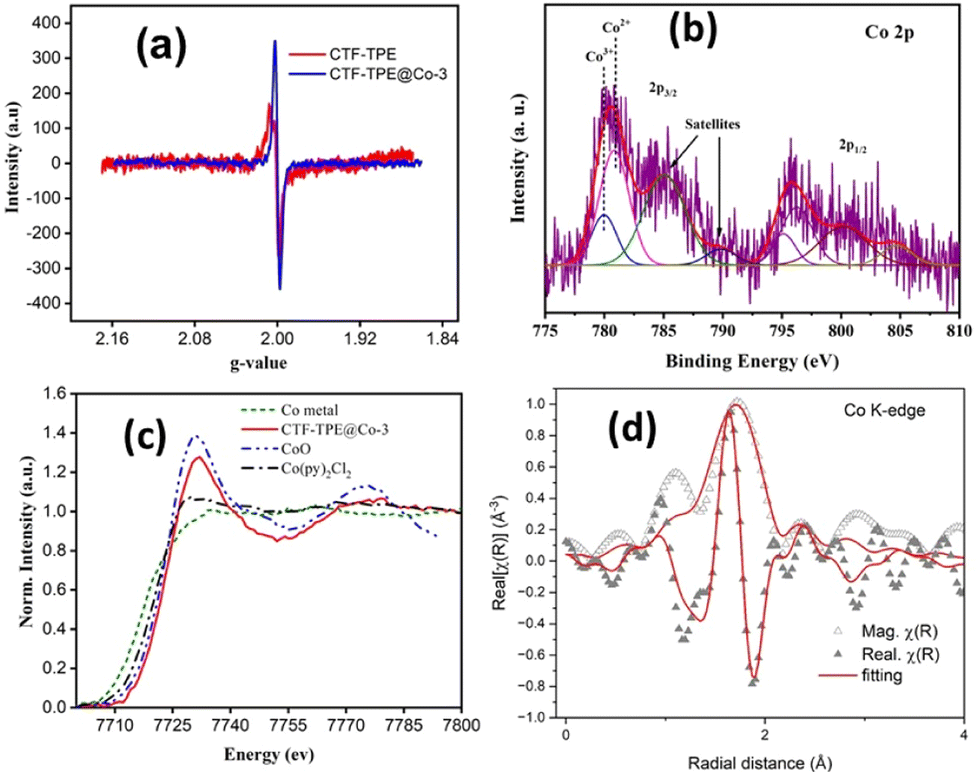
Furthermore, the solid-state electron paramagnetic resonance (EPR) spectra of CTF-TPE@Co-3 at room temperature were recorded to deduce the formation of any metal nanoparticles or clusters (Fig. 3a). Generally, the ferromagnetic NPs or clusters give an intense broad EPR peak at g values ≈2.870.45 However, there are no such EPR peaks observed at g values ≈2.870 for CTF-TPE@Co-3, which further reveals the absence of NPs or metal clusters within the CTF matrix. Additionally, EPR spectroscopy shows the presence of a single Lorentzian line at a g value of 1.9997 for both CTF-TPE and CTF-TPE@Co-3, originated from the unpaired electrons on aromatic rings.46 However, the EPR intensity of CTF-TPE has increased following the integration of Co2+ metal centers suggesting enhanced electron mobility in the π-conjugated CTF-TPE matrix and this observation aligns with the findings from the EIS analysis.
 | ||
| Fig. 3 (a) EPR spectra of CTF-TPE and CTF-TPE@Co-3, (b) XPS spectra of CTF-TPE@Co-3 of Co 2p, (c) XANES spectra recorded at the Co-k edge for Co metal, CTF-TPE@Co-3, CoO, and Co(py)2Cl2, and (d) EXAFS spectra of CTF-TPE@Co-3. | ||
Moreover, the EPR data do not reveal any detectable peak associated with ferromagnetic Co2+ single atoms. This absence may be attributed to the short relaxation time, which is in close agreement with previous reports on Co–Nx–C SACs.47 In addition, the chemical structure analysis of N-containing CTF-TPE and CTF-TPE@Co-3 was conducted using photoelectron spectroscopy (XPS). High-resolution C 1s XPS analysis revealed two distinctive peaks at a binding energy of 284.8 eV and 286.2 eV, indicating the presence of distinct carbon atom types within the framework (Fig. S6a, ESI†). The peak at approximately 284.8 eV is associated with one type of carbon atom (CC/C–C) and the broader peak at around 286.2 eV corresponds to the carbon atoms of the triazine unit (NC–N).48 Similarly, the deconvolution of N 1s XPS spectra displayed a peak at a binding energy of 397.7 eV attributed to the N atom of the triazine unit (CN–C) (Fig. S6c, ESI†).49 More interestingly, in the case of Co-loaded CTF-TPE the binding energy of the N 1s peak has been slightly shifted to 398.04 eV (Fig. S6d, ESI†). This shift in binding energy arises due to the coordination of Co to the N atom of the triazine moiety.50,51 The XPS analysis of cobalt in CTF-TPE@Co-3 revealed major binding energy peaks at 780.8 eV (2p3/2) and 796.2 eV (2p1/2) with 15.4 eV spin–orbit separation (Fig. 3b).52,53 These peaks provide a clear indication of the +2 oxidation state of the cobalt ion. The minor peaks with 15.2 eV spin–orbit separation observed at 779.9 eV and 795.1 eV suggest the presence of a minimal amount of Co3+.52,53 However, it is challenging to identify the Co2+ and Co3+ using the primary 2p peaks due to their slight variation in peak positions ranging from 0.1 to 1.5 eV. The Co 2p core level spectra of CTF-TPE@Co-3 can be differentiated by their distinct satellite peaks. The prominent satellite peaks of Co2+ occur at 785.03 eV and 800.21 eV. Hence, the binding energy difference of the cobalt 2p3/2 peak and its corresponding satellite peaks come around 4–6 eV assigned to Co2+, whereas the peak difference for Co3+ falls in the range of 9–10 eV (Fig. 3b). The relative concentration of Co2+ is found to be 90% compared to Co3+ in CTF-TPE@Co-3. The presence of a small amount of Co3+ may be ascribed to the surface oxidation or aerial oxidation of the sample.54 Notably, the Co 2p spectrum does not reveal any peaks corresponding to Co0 (typically at around 778.5 eV). This observation excludes the presence of any Co–Co metallic bond.55 The XPS study does not reveal any other cobalt species corresponding to CoO or cobalt metal.
Furthermore, to investigate more about the coordination number and the electronic environment of the cobalt single sites in CTF-TPE, extended X-ray absorption near-edge structure (XANES) spectra at the Co K-edge, referenced to the model compound Co(py)2Cl2, CoO, and Co-metal were thoroughly investigated. Also, the Co K-edge Fourier transform extended absorption fine structure (EXAFS) was extracted from the absorption spectrum of CTF-TPE@Co-3 in the k-range of (3–10) Å−1 and fitting was carried out roughly in the R-range of (1–3) Å. The Co K-edge XANES spectra of CTF-TPE@Co-3 with the reference compounds Co(py)2Cl2, CoO, and Co-metal are shown in Fig. 3c. The XANES curves show that the absorption threshold peak positions of CTF-TPE@Co-3 and reference compounds CoPy2Cl2 and CoO are look-alike indicating a +2 valence state of the Co atoms in the CTF-TPE@Co-3 compound, which is consistent with the XPS data. The Fourier-transformed EXAFS spectrum (Fig. 3d) of CTF-TPE@Co-3 demonstrates a prominent sharp peak at around 1.56 Å, which can be attributed to the Co2+ and nitrogen atom bond distance.21,25 No Co–Co peaks at 2.17 Å or larger bond distances were detected, confirming atomically dispersed Co species in CTF-TPE@Co-3.43,56
The morphology and texture of the sample were investigated using a scanning electron microscope (SEM) and transmission electron microscope (TEM) for CTF-TPE@Co-3. The SEM images indicate the disordered structure of CTF-TPE@Co-n (n = 1–4) (Fig. S7 and S9,† ESI). The SEM-EDX mapping confirms the presence of Co, N, C, and Cl which are homogeneously distributed within the CTF framework (Fig. S10a and b, ESI†). Furthermore, the elemental mapping acquired using a high-angle annular dark field scanning transmission electron microscope (HAADF-STEM) indicates the uniform distribution of Co, N, and C within the CTF framework (Fig. S11, ESI†). Notably, no images associated with CoO or metal clusters were identified in the high-resolution transmission electron microscope (HR-TEM) images (Fig. S12, ESI†). This observation serves as additional confirmation of the effective incorporation of single atomic Co sites embedded in the CTF scaffold. EDX and electron mapping depict the purity of the materials (Fig. S11, ESI†); crystalline and amorphous components are well dispersed throughout the solid matrix. Moreover, low and high magnification indicate that the smaller crystallites are embedded in the amorphous matrix; the particle size distribution curve indicates that the particles are around 2.5 nm (Fig. 4a–d). These tiniest crystallites are trapped in the stacked flexible structure on C and N controlled by the dopant Co2+ ion; this fact supports the selective site photocatalytic reductions. Fig. 5a, b, d and e characterize the different lattice fringes of the (001) plane and distorted lattice class of the (002) plane (also existing in the XRD graph, Fig. 2b) and SAED pattern (Fig. 5c), revealing that similar types of fringe distortions are dispersed throughout the metal doped CTF-TPE which enhances the photochemical performances.
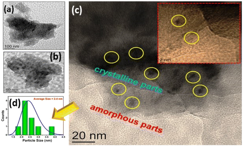 | ||
| Fig. 4 (a and b) Low-magnification TEM images of CTF-TPE@Co-3, (c) TEM image displaying both the crystalline and amorphous nature of the sample (inset shows its HRTEM image), and (d) particle size distribution (PSD) of the crystalline parts. | ||
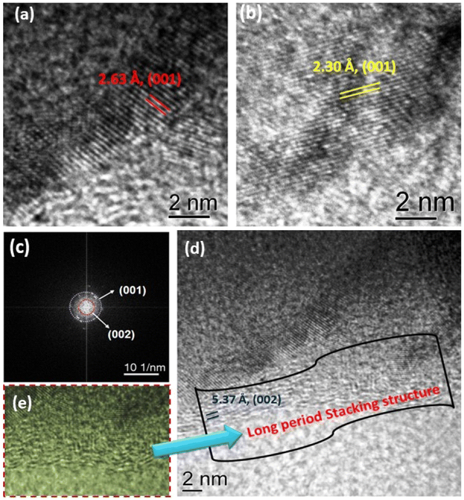 | ||
| Fig. 5 (a and b) High-magnification TEM images of CTF-TPE@Co-3 showing different lattice fringes of the (001) plane, (c) corresponding SAED pattern, (d) HRTEM image of CTF-TPE@Co-3 exhibiting a distorted (002) plane, and (e) corresponding magnified view. | ||
In the last decade, it has been observed that CTFs are well-known for high CO2 adsorption. Motivated by the high CO2 adsorption in the CTF-TPE material, photochemical CO2 reduction was studied. Indeed, the efficacy of the catalyst's photoreduction activity relies on two additional factors: the optical absorption properties and the efficiency of feasible transfer and separation of photoinduced charge. These two factors play a pivotal role in shaping the catalyst's ability to absorb light and effectively utilize it to induce and separate charges. UV-VIS spectroscopy of the synthesized catalysts has been performed (Fig. S13a, ESI†). Both CTF-TPE and CTF-TPE@Co-n (n = 1 to 4) exhibited a wide absorption peak ranging from 350–450 nm with a maximum absorption (λmax) occurring at 355 nm. Notably, the inclusion of Co in CTF-TPE resulted in higher photo absorption in the region (350–450 nm) compared to pristine CTF-TPE (Fig. S13a, ESI†). This observation suggests a strong interaction between the metal and the framework, indicating promising host–guest interaction.57,58 The band gap for CTF-TPE@Co-3 has been calculated from UV-vis absorption spectra using the Tauc formula and was found to be 2.42 eV (Fig. S13c, ESI†). Furthermore, the photoluminescence experiments were performed for CTF-TPE and CTF-TPE@Co-n (n = 1 to 4) by exciting the materials at a wavelength of 360 nm. The materials CTF-TPE and CTF-TPE@Co-n (n = 1 to 4) exhibited maximum fluorescence intensity at 520 nm. But, more importantly, the fluorescence intensity of CTF-TPE@Co-n gets quenched dramatically by many fold as compared to its counterpart, CTF-TPE (Fig. S13b, ESI†) as the metal loading increases. This observation implies a probability of higher charge separation thereby promoting a lower recombination rate of photoinduced electrons and holes within CTF-TPE@Co.59 In addition, the transient photocurrent response shows a higher current density of the cobalt-incorporated CTF than the pristine CTF when illuminated with visible light. This finding provides additional confirmation of the enhanced electrical conductivity and prolonged lifetime of charge carriers (Fig. 6e). Moreover, electrochemical impedance spectroscopy (EIS) was performed to assess the charge transfer proficiency. The EIS Nyquist plot of CTF-TPE and CTF-TPE@Co-n exhibited a semicircle with a much smaller radius for cobalt-loaded CTF-TPE compared to bare CTF (Fig. 6d). Smaller semicircles reveal lower charge transfer resistance in CTF-TPE@Co-3 thereby accelerating the electron transfer process. This phenomenon is likely a contributing factor to the enhanced photocatalytic activity observed in CTF-TPE@Co-3.60
 | ||
| Fig. 6 (a) CO evolution using different Co-loaded CTF-n (n = 1, 2, 3, 4), and a negligible amount of formate is not shown. (b) Reaction conditions for CO2 reduction. (c) 7 h long photocatalytic run using CTF-TPE@Co-3. (d) EIS Nyquist plot. (e) Transient photocurrent response of CTF-TPE@Co-n (n = 1 to 4). (f) Recyclability test of CTF-TPE@Co-3. | ||
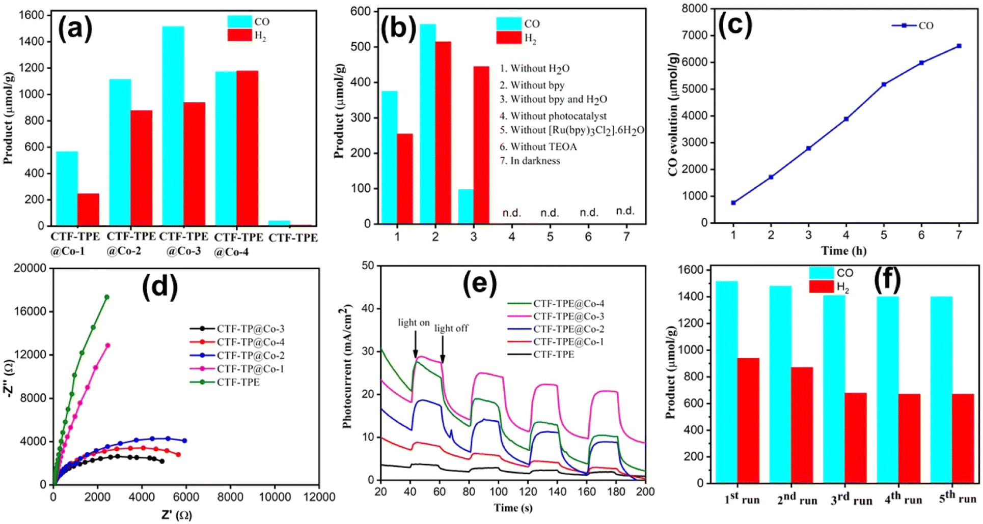
Taking into account the catalytic characteristics of the Co–ligand complex in the CO2 reduction reaction61 combined with the strong affinity of CTF-TPE for CO236 as well as the excellent chemical stability of CTF-TPE, we have examined the efficacy of the synthesized single-site cobalt-embedded CTF-TPE towards photocatalytic CO2 reduction. The photocatalytic CO2 reduction reaction has been carried out in a mixture of CH3CN and H2O solvents under visible light irradiation (λ = 420 nm) using TEOA as a sacrificial electron donor, [Ru(bpy)3]2+ as a photosensitizer and 2,2′-bipyridine as a cocatalyst (Fig. S22, ESI†). All the components involved in this CO2 reduction reaction, including the sacrificial electron donor, photosensitizer, catalyst, and cocatalyst, are essential for efficient photocatalytic CO2 reduction reaction. The photocatalytic activity of CTF-TPE@Co materials towards CO2 reduction has been optimized by varying the quantity of introduced Co species in the CTF-TPE scaffold (Fig. 6a). In the absence of Co metal sites, CTF-TPE has shown poor catalytic activity, yielding a total CO production of only 40 μmol g−1 in 2 h under optimal conditions. This poor performance of CTF-TPE towards CO evolution may be ascribed to the higher recombination rate of electron–hole pairs during photocatalysis.
However, the incorporation of single Co2+ metal centers into CTF-TPE boosts its photocatalytic activity, which is consistent with the findings from the photoelectrochemical analysis. The outcomes of the photocatalytic carbon dioxide reduction experiments demonstrate that as the cobalt loading increases, the production of CO also increases (Fig. 6a). Notably, among all the prepared photocatalysts, the optimal catalytic efficiency is achieved with a cobalt loading of 3.1 wt% (CTF-TPE@Co-3). CTF-TPE@Co-3 shows the highest photocatalytic efficiency with a CO and H2 generation of 1515 μmol g−1 and 938 μmol g−1 within 2 h, respectively. A negligible amount of formate was also detected. Additionally, CTF-TPE@Co-3 has been employed for long-run photocatalytic experiments demonstrating a CO evolution of 6616 μmol g−1 over 7 h (Fig. 6c), which is higher than that of many previously reported CTF-based photocatalysts (Table S4, ESI†). The turnover number of CO evolution by CTF-TP@Co-3 is 13.32 after 7 h of irradiation. However, a minute quantity of HCOO− (0.016 μmol g−1) has been detected by ion chromatography (Fig. S21a, ESI†). No other liquid hydrocarbon products including CH3OH and C2H5OH have been found in 1H NMR analysis (Fig. S21b, ESI†). But at higher concentrations of cobalt (5.9 wt% Co loading), the catalytic efficiency of CTF-TPE@Co-4 declined with a CO and H2 production of 1172 μmol g−1 and 1178 μmol g−1, respectively (Fig. 6a). The reason behind this phenomenon may be attributed to the possibility that a higher concentration of Co can result in the formation of cobalt aggregates or clusters (Fig. S17, ESI†). This highlights the pivotal role of cobalt concentration in driving CO generation and underscores the optimal conditions for catalytic efficiency. In addition, a set of controlled experiments was conducted to know the key role of all the elements in this high CO production over CTF-TPE@Co-3 (Fig. 6b). The significant reduction in photocatalytic H2 evolution to 254.03 μmol g−1 without the presence of H2O suggests that the H2 production may originate either from TEOA or H2O sources. However, the removal of TEOA from the reaction mixture resulted in photocatalytic inactivity of CTF-TPE@Co-3 for CO2 reduction. These findings suggest that H2O acts as a proton source and TEOA can serve as a sacrificial electron donor for this CO2 conversion system. More interestingly, we have achieved a CO evolution of 1515 μmol g−1 only when 2,2′-bipyridine has been added in the reaction mixture (Fig. 6a). However, in its absence, the CO evolution was lower, measuring only 564 μmol g−1. Hence, 2,2′-bipyridine, TEOA, and H2O are crucial for high-efficiency photocatalytic CO2 reduction. Moreover, no CO has been detected in the absence of light or a photocatalyst revealing the photocatalytic nature of the reaction. No carbonaceous products have been noticed under the Ar atmosphere, which confirms that the CO is coming from CO2 rather than the organic solvent used in the reaction. Additionally, an isotope labeling experiment was conducted in the presence of 13CO2 to confirm the origin of CO generation. The gaseous product was analyzed using gas chromatography-mass spectrometry (GC-MS), revealing a distinct peak at m/z = 29. This supports the production of CO from CO2 gas, rather than from any other organic compounds (Fig. S15, ESI†).62 Additionally, the heterogeneous nature of the CO2 reduction reaction was further established by performing the recyclability and reusability tests (Fig. 6f). The photocatalytic stability of CTF TPE@Co-3 was assessed through a 2 h illumination cycle. As illustrated in Fig. 6f, the rates of CO and H2 production from CTF-TPE@Co-3 remained nearly constant even after five cycles run under the same experimental conditions. This observation confirms the excellent long-term stability of CTF-TPE@Co-3 for CO2 reduction. Furthermore, no noticeable change has been observed in the PXRD pattern and FT-IR peaks of CTF-TPE@Co-3 after photocatalysis, demonstrating its stability during the reaction (Fig. S16, ESI†). Also, the XPS analysis of recovered samples showed that the oxidation state of Co remains unchanged from its precatalysis state which shows the stability of the photocatalyst (Fig. S18, ESI†). These results highlight the significant advantages of employing CTF-TPE for embedding single Co atoms, resulting in enhanced activity and outstanding durability.
Now, to understand the CO2 reduction mechanism, we have carried out photophysical and electrochemical studies. First, we have investigated whether the photoexcited [Ru(bpy)3]2+* underwent oxidative or reductive quenching for initiating CO2RR cycles. The emission intensity of [Ru(bpy)3]2+ has been gradually quenched with the incremental addition of TEOA (Fig. 7a). In contrast, there is no decrease in emission intensity observed upon the addition of CTF-TPE@Co-3 (Fig. 7b). This suggests a reductive quenching mechanism for the CO2RR, wherein electron transfer occurs from TEOA to photoexcited [Ru(bpy)3]2+* to generate [Ru(bpy)3]+, and then finally [Ru(bpy)3]+ injects electrons into the cobalt center (Fig. 8 (top)). The flat band potential of the photocatalyst CTF-TPE@Co-3 is found to be −1.12 V vs. Ag/AgCl (−0.92 V vs. NHE) using Mott Schottky measurements at different frequencies in 2 M Na2SO4 electrolyte (Fig. S13d, ESI†). Hence, its valence band was calculated to be 1.5 V (Fig. 8 (bottom)). The Mott–Schottky plot of all the CTF-TPE@Co-n (1 to 4) shows a positive slope demonstrating the n-type nature of the semiconductors (Fig. S14, ESI†).63 The reduction potential of the LUMO of CTF-TPE@Co-n (n = 1, 2, 4) is found to be −0.851 V, −0.881 V, and −0.826 V, respectively from the Mott–Schottky plot (Fig. S14, ESI†). Now, it is evident that the reduction potential of CTF-TPE@Co-3 is less negative than the [Ru(bpy)3]2+ ((E[Ru(bpy)3]2+*/[Ru(bpy)3]+) = −1.25 V vs. NHE), but more negative than the reduction potential of CO2 to CO (E(CO2/CO) = −0.52 V vs. NHE)22 (Fig. 8 (bottom)). This suggests an electron transfer from the photosensitizer to CTF-TPE@Co-3, facilitating electron injection from the catalyst to CO2 and driving the photocatalytic conversion of CO2 to CO (Fig. 8 (bottom)).
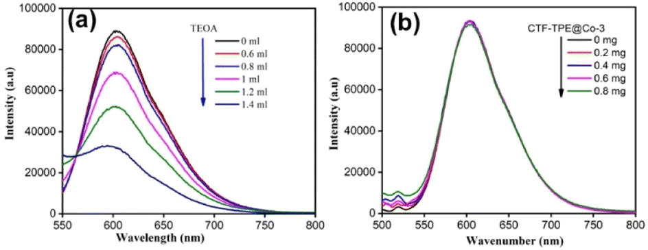 | ||
| Fig. 7 (a) Fluorescence spectra of [Ru(bpy)3]2+ in the presence of TEOA. (b) Fluorescence spectra of [Ru(bpy)3]2+ in the presence of CTF-TPE@Co-3. | ||
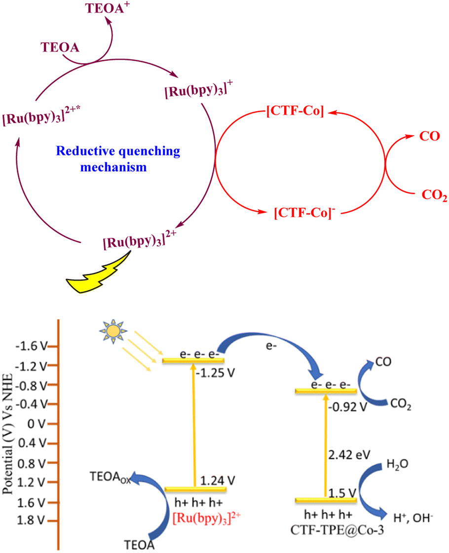 | ||
| Fig. 8 Reductive quenching pathway of [Ru(bpy)3]2+ during the photocatalytic reaction (top); possible potential diagram for CO2 reduction by CTF-TPE@Co-3 (bottom). | ||
Based on the aforementioned results and discussions, we have proposed a plausible mechanism for the photocatalytic CO2 reduction reaction as depicted in Fig. 8. Under light irradiation, [Ru(bpy)3]2+ and CTF-TPE@Co-3 create excited electron–hole pairs and promote the electrons to the excited state [Ru(bpy)3]2+*. Subsequently, TEOA reductively quenched [Ru(bpy)3]2+* to generate the reduced photosensitizer [Ru(bpy)3]+*. The [Ru(bpy)3]+* transfers the photogenerated electrons to the Co active sites for CO2 reduction to CO. On the other hand the valence band location of CTF-TPE@Co-3 readily overcomes the water oxidation threshold potential.64 Thus, the photogenerated holes in the VB of CTF-TPE@Co-3 oxidize H2O to give H+ and HO− which is a crucial step in the photocatalytic CO2 reduction process.65 The holes selectively react with OH− species to prevent electron–hole recombination, and simultaneously, H+ unite to generate H2, which is detected in GC (Fig. S20, ESI†). This also supports the proposed mechanism.
Furthermore, a leaching test was conducted to verify the heterogeneous nature of the photocatalyst in the context of the photocatalytic CO2 reduction reaction (Fig. S19, ESI†). In this experimental procedure, the catalyst was isolated after 2 hours of photocatalytic run, and subsequently, the CO2 reduction reaction was executed using the filtrate from the reaction mixture. Significantly, no CO evolution was observed in the GC chromatogram after the removal of the catalyst, affirming that no metal atoms had leached out of the CTF-TPE@Co-3 moiety. Thus, this demonstrates the pronounced heterogeneity of CTF-TPE@Co-3. Moreover, the catalytic performance of CTF-TPE@Co-3 has been investigated using direct sun light to mimic natural photosynthesis and it gives 170 μmol g−1 CO and 8.0 μmol g−1 H2 in 3 h in a cloudy environment (Fig. S23, ESI†).
Conclusions
In summary, we have showcased the successful preparation of an effective CTF-based photocatalyst by anchoring single Co2+ active sites within a triazine framework for CO2 reduction under visible light irradiation. The synthesized CTF-TPE material, featuring isolated cobalt single sites, demonstrated remarkable efficiency in photocatalytic CO2 reduction in the presence of a dye and sacrificial electron donor. It achieved a CO generation of 6616 μmol g−1 for a continuous 7 h run. This photocatalytic activity is on par with the performance of other state-of-the-art heterogeneous catalysts documented in the literature under analogous conditions (Table S4, ESI†). This superior photocatalytic activity of CTF-TPE@Co-3 may be attributed to the coordination of Co2+ sites within the CTF-TPE scaffold, which facilitates electron transfer from the photosensitizer to the catalyst and enhances the system's CO2 adsorption capacity, thereby increasing its overall photocatalytic activity. The results suggest that CTF-TPE is a potential support to stabilize the single Co atom through strong coordination of metals and nitrogen atoms of triazine rings. This study unveils a promising strategy for the fabrication of an effective triazine-based photocatalyst based on Earth-abundant transition metals and we believe that our work will open a new avenue for designing and constructing next-generation photocatalysts in the realm of solar fuels.Conflicts of interest
There are no conflicts to declare.Acknowledgements
This work was supported financially by SERB (EEQ/2020/000357), DST-INSPIRE (DST/INSPIRE/04/2017/001072), and a UGC (No. F. 30-552/2021(BSR)) start-up grant. AJ acknowledges the Council of Scientific and Industrial Research (CSIR), Govt of India, for the fellowship. The R-XAS facility at the Sophisticated Instrumentation Centre, IIT Indore, is acknowledged for EXAFS measurement. Dr Sandeep Kumar Dey is acknowledged for the solid-state NMR and XPS measurements. Dr Parthasarathi Bera is acknowledged for valuable discussion on XPS. The authors wish to thank the Department of Industrial Chemistry and Applied Chemistry, Ramakrishna Mission Vidyamandira, and Belur Math for providing the ion chromatography instrumental facilities.Notes and references
- C. R. Timothy, D. K. Dilek, R. Y. Steven, S. Yogesh, T. S. Thomas and N. G. Daniel, Chem. Rev., 2010, 110(11), 6474–6502 CrossRef PubMed.
- S. Das and W. M. A. Wan Daud, RSC Adv., 2014, 4, 20856–20893 RSC.
- D. Li, M. Kassymova, X. Cai, S.-Q. Zang and H.-L. Jiang, Coord. Chem. Rev., 2020, 412, 213262 CrossRef CAS.
- L. Cheng, Q. J. Xiang, Y. L. Liao and H. W. Zhang, Energy Environ. Sci., 2018, 11, 1362–1391 RSC.
- S. N. Habisreutinger, L. Schmidt Mende and J. K. Stolarczyk, Angew. Chem., Int. Ed., 2013, 52, 7372–7408 CrossRef CAS PubMed.
- S. W. Cao, J. X. Low, J. G. Yu and M. Jaroniec, Adv. Mater., 2015, 27, 2150–2176 CrossRef CAS PubMed.
- J. Fu, B. Zhu, C. Jiang, B. Cheng, W. You and J. Yu, Small, 2017, 13, 1603938 CrossRef PubMed.
- Q. Lang, W. Hu, P. Zhou, T. Huang, S. Zhong, L. Yang, J. Chen and S. Bai, Nanotechnology, 2017, 28, 484003 CrossRef PubMed.
- M. Zhou, S. Wang, P. Yang, Z. Luo, R. Yuan, A. M. Asiri, M. Wakeel and X. Wang, Eur. J. Chem., 2018, 24, 18529–18534 CrossRef CAS PubMed.
- H. Rao, L. C. Schmidt, J. Bonin and M. Robert, Nature, 2017, 548, 74–77 CrossRef CAS PubMed.
- H. Takeda, K. Ohashi, A. Sekine and O. Ishitani, J. Am. Chem. Soc., 2016, 138, 4354–4357 CrossRef CAS PubMed.
- Y. Wang, X. Liu, X. Han, R. Godin, J. Chen, W. Zhou, C. Jiang, J. Thompson, K. Mustafa, S. Shevlin, J. Durrant, Z. Guo and J. Tang, Nat. Commun., 2020, 11, 2531 CrossRef CAS PubMed.
- M. F. Kuehnel, C. D. Sahm, G. Neri, J. R. Lee, K. L. Orchard, A. J. Cowan and E. Reisner, Chem. Sci., 2018, 9, 2501–2509 RSC.
- S. Roy and E. Reisner, Angew. Chem., Int. Ed., 2019, 58, 12180–12184 CrossRef CAS PubMed.
- Y. Kuramochi, O. Ishitani and H. Ishida, Coord. Chem. Rev., 2018, 373, 333 CrossRef CAS.
- J. Bonin, A. Maurin and M. Robert, Coord. Chem. Rev., 2017, 334, 184 CrossRef CAS.
- J. J. Mao, C. T. He, J. J. Pei, W. X. Chen, D. S. He, Y. Q. He, Z. B. Zhuang, C. Chen, Q. Peng and D. S. Wang, Nat. Commun., 2018, 9, 4958 CrossRef PubMed.
- S. Paul, S. Sarkar, A. Adalder, S. Kapse, R. Thapa and U. K. Ghorai, ACS Sustainable Chem. Eng., 2023, 11(16), 6191–6200 CrossRef CAS.
- W. Zhong, R. Sa, L. Li, Y. He, L. Li, J. Bi, Z. Zhuang, Y. Yu and Z. Zou, J. Am. Chem. Soc., 2019, 141, 7615–7621 CrossRef CAS PubMed.
- X. Wang, Z. Fu, L. Zheng, C. Zhao, X. Wang, S. Y. Chong, F. McBride, R. Raval, M. Bilton, L. Liu, X. Wu, L. Chen, R. S. Sprick and A. I. Cooper, Chem. Mater., 2020, 32, 9107–9114 CrossRef CAS.
- X. Hu, L. Zheng, S. Wang, X. Wang and B. Tan, Chem. Commun., 2022, 58, 8121 RSC.
- J. Wang, W. Zhu, F. Meng, G. Bai, Q. Zhang and X. Lan, ACS Catal., 2023, 13, 4316–4329 CrossRef CAS.
- J. L. Liang, Q. Q. Song, J. H. Wu, Q. Lei, J. Li, W. Zhang, Z. M. Huang, T. X. Kang, H. Xu and P. Wang, ACS Nano, 2022, 16, 4152–4161 CrossRef CAS PubMed.
- Z. J. Li, D. H. Wang, Y. E. Wu and Y. D. Li, Natl. Sci. Rev., 2018, 5, 673–689 CrossRef CAS.
- P. Huang, J. Huang, S. A. Pantovich, A. D. Carl, T. G. Fenton, C. A. Caputo, R. L. Grimm, A. I. Frenkel and G. Li, J. Am. Chem. Soc., 2018, 140, 16042 CrossRef CAS PubMed.
- (a) W. Huang, Z. J. Wang, B. C. Ma, S. Ghasimi, D. Gehrig, F. Laquai, K. Landfester and K. A. I. Zhang, J. Mater. Chem. A, 2016, 4, 7555–7559 RSC; (b) Z. Cheng, H. Pan, H. Zhong, Z. Xiao, X. Li and R. Wang, Adv. Funct. Mater., 2018, 28, 1707597 CrossRef.
- S. Kuecken, A. Acharjya, L. Zhi, M. Schwarze, R. Schomaecker and A. Thomas, Chem. Commun., 2017, 53, 5854–5857 RSC.
- J. Xie, S. A. Shevlin, Q. Ruan, S. J. A. Moniz, Y. Liu, X. Liu, Y. Li, C. C. Lau, Z. X. Guo and J. Tang, Energy Environ. Sci., 2018, 11, 1617–1624 RSC.
- S. Zhang, G. Cheng, L. Guo, N. Wang, B. Tan and S. Jin, Angew. Chem., Int. Ed., 2019, 59, 6007–6014 CrossRef PubMed.
- G. C. Huang, Q. Niu, J. W. Zhang, H. M. Huang, Q. S. Chen, J. H. Bi and L. Wu, Chem. Eng. J., 2022, 427, 131018 CrossRef CAS.
- G. C. Huang, G. Y. Lin, Q. Niu, J. H. Bi and L. Wu, J. Mater. Sci. Technol., 2022, 116, 41–49 CrossRef CAS.
- C. Lu, J. Yang, S. Wei, S. Bi, Y. Xia, M. Chen, Y. Hou, M. Qiu, C. Yuan, Y. Su, F. Zhang, H. Liang and X. Zhuang, Adv. Funct. Mater., 2019, 29, 1806884 CrossRef.
- S. Yang, R. Sa, H. Zhong, H. Lv, D. Yuan and R. Wang, Adv. Funct. Mater., 2022, 32, 2110694 CrossRef CAS.
- P. Kuhn, M. Antonietti and A. Thomas, Angew. Chem., Int. Ed., 2008, 47, 3450–3453 CrossRef CAS PubMed.
- H. A. Patel, F. Karadas, A. Canlier, J. Park, E. Deniz, Y. Jung, M. Atilhan and C. T. Yavuz, J. Mater. Chem., 2012, 22, 8431–8437 RSC.
- A. Bhunia, I. Boldog, A. Möller and C. Janiak, J. Mater. Chem. A, 2013, 1, 14990–14999 RSC.
- (a) I. D. Wessely, A. M. Schade, S. Dey, A. Bhunia, A. Nuhnen, C. Janiak and S. Bräse, Materials, 2021, 14, 3214 CrossRef CAS PubMed; (b) S. Dey, A. Bhunia, I. Boldog and C. Janiak, Microporous Mesoporous Mater., 2017, 241, 303–315 CrossRef CAS; (c) S. Dey, A. Bhunia, H. Breitzke, P. B. Groszewicz, G. Buntkowsky and C. Janiak, J. Mater. Chem. A, 2017, 5, 3609–3620 RSC.
- J. Weber, M. Antonietti and A. Thomas, Macromolecules, 2008, 41, 2880–2885 CrossRef CAS.
- N. Ritter, I. Senkovska, S. Kaskel and J. Weber, Macromol. Rapid Commun., 2011, 32, 438–443 CrossRef CAS PubMed.
- R. Dawson, L. A. Stevens, T. C. Drage, C. E. Snape, M. W. Smith, D. J. Adams and A. I. Cooper, J. Am. Chem. Soc., 2012, 134, 10741–10744 CrossRef CAS PubMed.
- X. Zhu, C. Tian, S. M. Mahurin, S.-H. Chai, C. Wang, S. Brown, G. M. Veith, H. Luoll, H. Liu and S. Dai, J. Am. Chem. Soc., 2012, 134, 10478–10484 CrossRef CAS PubMed.
- D. N. Li, Y. K. Fan, H. R. Yuan, L. F. Deng, J. Z. Yang, Y. Chen and B. Luo, Energy Fuels, 2020, 34, 13089–13095 CrossRef CAS.
- H. Jin, P. Li, P. Cui, J. Shi, W. Zhou, X. Yu, W. Song and C. Cao, Nat. Commun., 2022, 13, 723 CrossRef CAS PubMed.
- X.-Y. Dong, Y.-N. Si, Q.-Y. Wang, S. Wang and S.-Q. Zang, Adv. Mater., 2021, 33, 2101568 CrossRef CAS PubMed.
- P. Kumar, K. Kannimuthu, A. S. Zeraati, S. Roy, X. Wang, X. Wang, S. Samanta, K. A. Miller, M. Molina, D. Trivedi, J. Abed, M. A. C. Mata, H. A. Mahayni, J. Baltrusaitis, G. Shimizu, Y. A. Wu, A. Seifitokaldani, E. H. Sargent, P. M. Ajayan, J. Hu and Md G. Kibria, J. Am. Chem. Soc., 2023, 145, 8052–8063 CrossRef CAS PubMed.
- G. G. Zhang, M. W. Zhang, X. X. Ye, X. Q. Qiu, S. Lin and X. C. Wang, Adv. Mater., 2014, 26, 805–809 CrossRef CAS PubMed.
- X. Li, A. E. Surkus, J. Rabeah, M. Anwar, S. Dastigir, H. Junge, A. Brückner and M. Beller, Angew. Chem., Int. Ed., 2020, 59, 15849–15854 CrossRef CAS PubMed.
- G. G. Zhang, J. S. Zhang, M. W. Zhang and X. C Wang, J. Mater. Chem., 2012, 22, 8083–8091 RSC.
- Z. Q. Luo, S. Lim, Z. Q. Tian, J. Z. Shang, L. F. Lai, B. MacDonald, C. Fu, Z. X. Shen, T. Yu and J. Y. Lin, J. Mater. Chem., 2011, 21, 8038–8044 RSC.
- X. Zhu, C. C. Tian, S. M. Mahurin, S. H. Chai, C. M. Wang, S. Brown, G. M. Veith, H. M. Luo, H. L. Liu and S. Dai, J. Am. Chem. Soc., 2012, 134, 10478 CrossRef CAS PubMed.
- L. S. Ma, W. B. Hu, B. B. Mei, H. Liu, B. Yuan, J. Zang, T. Chen, L. L. Zou, Z. Q. Zou, B. Yang, Y. Yu, J. Y. Ma, Z. Jiang, K. Wen and H. Yang, ACS Catal., 2020, 10, 4534 CrossRef CAS.
- T. Baidya, T. Murayama, S. Nellaiappan, N. K. Katiyar, P. Bera, O. Safonova, M. Lin, K. R. Priolkar, S. Kundu, B. S. Rao, P. Steiger, S. Sharma, K. Biswas, S. K. Pradhan, N. Lingaiah, K. D. Malviya and M. Haruta, J. Phys. Chem. C, 2019, 123, 19557–19571 CrossRef CAS.
- T. Baidya, T. Murayama, P. Bera, O. V. Safonova, P. Steiger, N. K. Katiyar, K. Biswas and M. Haruta, J. Phys. Chem. C, 2017, 121, 15256–15265 CrossRef CAS.
- M. Liu, Z. Wang, J. Liu, G. Wei, J. Du, Y. Li, C. An and J. Zhang, J. Mater. Chem. A, 2017, 5, 1035–1042 RSC.
- R. Ma, X. Cui, Y. Wang, Z. Xiao, R. Luo, L. Gao, Z. Weie and Y. Yang, J. Mater. Chem. A, 2022, 10, 5918 RSC.
- C. Gao, S. Chen, Y. Wang, J. Wang, X. Zheng, J. Zhu, L. Song, W. Zhang and Y. Xiong, Adv. Mater., 2018, 30, 1704624 CrossRef PubMed.
- Q. Huang, J. Yu, S. Cao, C. Cui and B. Cheng, Appl. Surf. Sci., 2015, 358, 350–355 CrossRef CAS.
- P. Xia, B. Zhu, J. Yu, S. Cao and M. Jaroniec, J. Mater. Chem. A, 2016, 5, 3230 RSC.
- W. K. Jo, S. Kumar, S. Eslava and S. Tonda, Appl. Catal., B, 2018, 239, 586–598 CrossRef CAS.
- M. E. Khan, M. M. Khan and M. H. Cho, New J. Chem., 2015, 39, 8121–8129 RSC.
- S. Fernandez, F. Franco, C. Casadevail, V. M. Diaconescu, J. M. Luis and J. L. Fillol, J. Am. Chem. Soc., 2020, 142(1), 120–133 CrossRef CAS PubMed.
- X. H. Lin, Z. D. Xie, B. Su, M. Zheng, W. X. Dai, Y. D. Hou, Z. X. Ding, W. Lin, Y. X. Fang and S. B. Wang, Nanoscale, 2021, 13, 18070 RSC.
- J.-S. Qin, S. Yuan, L. Zhang, B. Li, D.-Y. Du, N. Huang, W. Guan, H. F. Drake, J. Pang, Y.-Q. Lan, A. Alsalme and H.-C. Zhou, J. Am. Chem. Soc., 2019, 141, 2054–2060 CrossRef CAS PubMed.
- B. M. Hunter, H. B. Gray and A. M. Müller, Chem. Rev., 2016, 116, 14120–14136 CrossRef CAS PubMed.
- C. B. Hiragond, N. S. Powar, J. Lee and S.-I. In, Small, 2022, 18, 2201428 CrossRef CAS PubMed.
Footnote |
| † Electronic supplementary information (ESI) available: IR, TGA, PXRD, XPS, UV-vis, N2 uptake, TEM, SEM, and Mott–Schottky plot. See DOI: https://doi.org/10.1039/d3ta06987g |
| This journal is © The Royal Society of Chemistry 2024 |