
Correlating the structural transformation and properties of ZIF-67 during pyrolysis, towards electrocatalytic oxygen evolution†
Sara
Frank
 a,
Mads
Folkjær
a,
Mads L. N.
Nielsen
bc,
Melissa J.
Marks
a,
Henrik S.
Jeppesen
d,
Marcel
Ceccato
a,
Simon J. L.
Billinge
e,
Jacopo
Catalano
*a and
Nina
Lock
*bc
a,
Mads
Folkjær
a,
Mads L. N.
Nielsen
bc,
Melissa J.
Marks
a,
Henrik S.
Jeppesen
d,
Marcel
Ceccato
a,
Simon J. L.
Billinge
e,
Jacopo
Catalano
*a and
Nina
Lock
*bc
aDepartment of Biological and Chemical Engineering, Aarhus University, Åbogade 40, 8200 Aarhus N, Denmark. E-mail: jcatalano@bce.au.dk
bInterdisciplinary Nanoscience Center (iNANO), Aarhus University, Gustav Wieds Vej 14, 8000 Aarhus C, Denmark
cCarbon Dioxide Activation Center (CADIAC), Department of Biological and Chemical Engineering, Aarhus University, Åbogade 40, 8200 Aarhus N, Denmark. E-mail: nlock@bce.au.dk
dDeutsches Elektronen-Synchrotron (DESY), Notkestraße 85, D-22607 Hamburg, Germany
eDepartment of Applied Physics and Applied Mathematics, Columbia University, New York 10027, USA
First published on 13th December 2023
Abstract
There is an emerging interest in using pyrolyzed metal–organic frameworks (MOFs) for electrocatalytic applications. While the MOF precursor and the final pyrolyzed catalyst are usually investigated, the pyrolysis process itself is often treated as a ‘black box’, and the phase transition is poorly understood as a result. The process further depends on the specific experimental setup, in terms of e.g. the heating ramp, carrier gas and heat- and mass transport, complicating the comparison of catalyst properties across the literature. In this study, we use in situ X-ray absorption spectroscopy and total scattering to elucidate the thermal decomposition of ZIF-67 to a MOF-derived nanomaterial (MDN), which is composed of cobalt nanoparticles embedded in a carbonaceous matrix. Furthermore, we demonstrate that the phase transition can be halted at different stages, allowing the corroboration of the in situ analyses with properties of ex situ MDNs produced by pyrolyzing ZIF-67 in a tube furnace at various temperatures and durations. The electrochemical properties of the ex situ MDNs were studied systematically towards the oxygen evolution reaction (OER), facilitating the correlation of catalyst properties and structural characteristics for the ZIF-67 based catalysts. Although ZIF-67 is generally acclaimed for its thermal stability up to approx. 400 °C, this study demonstrates the emergence of disorder at lower temperatures (approx. 150 °C). This disorder manifests as distortions of the framework by contraction of nearest neighbor Co–N bond distance, and an initial formation of cobalt clusters. Although this disorder resulted in poorer electrocatalytic performance relative to pristine ZIF-67, extending the temperature and duration of the pyrolysis process produced MDNs with superior electrochemical properties relative to pristine ZIF-67. The best catalyst exhibits the lowest overpotential against the oxygen evolution reaction of 416 mV, which is an improvement of 200 mV compared to the pristine MOF catalyst. The more heavily pyrolyzed samples are composed of cobalt nanoparticles with a bimodal size distribution at 1.4 nm and 7.1 nm (pyrolyzed at 550 °C for 8 or 12 h) and 1.7 nm and 9.4 nm (pyrolyzed at 650 °C) confined in a carbonaceous matrix and with BET surface areas of 40–124 m2 g−1.
1 Introduction
Metal–organic frameworks (MOFs) composed of inorganic metal nodes and organic linkers have gained increased attention as electrocatalysts in recent years. MOFs not only offer a high degree of tuneability, but also high porosities and surface areas, which can expose a large number of active metal sites, resulting in a large mass activity per metal atom.1,2 Despite these promising properties, MOFs are often plagued by low thermal and chemical stability, which results in restructuring or degradation of the frameworks under catalytic operating conditions.3–5 One strategy which can overcome the low stability is to pyrolyze the MOFs in order to produce MOF-derived nanomaterials (MDNs). The resulting MDNs typically comprise metal and/or metal-oxide nanoparticles embedded in a carbonaceous matrix with a graphitic nature.6–10 The graphitic carbon matrix can improve conductivity and hinder agglomeration of the nanoparticles formed during pyrolysis.11–14 In addition, several properties of the parent MOF structure will be inherited by the MDN, such as porosity and morphology. The promising properties of the MDNs are therefore numerous, and these materials have proven to be highly effective and stable electrocatalysts.15–19Mechanistic insights into the formation of MDNs are crucial for rational design of high-performance catalysts, however the pathway from MOF to MDN is generally poorly understood. Intermediate phases are often overlooked, as many studies only investigate the pristine and final compounds, and changes in the degree of order/disorder during the pyrolysis process are seldom studied. However, both the intermediate phases and degree of disorder are important to acknowledge, as they influence the properties of the final material. A small number of studies have elucidated the transient phase behavior and time/temperature dependence of the thermal treatment of MOFs by means of in situ X-ray diffraction (XRD), total scattering and pair distribution function (TS/PDF) analysis, and/or X-ray absorption spectroscopy (XAS).13,20,21 The combination of these techniques details the transformation from MOF to MDN on both a local and long-range scale, thus mapping both crystalline and non-crystalline changes. When combined with catalytic studies, such detailed structural investigations enable correlations of the structural evolution with the catalytic properties throughout the different stages of the pyrolysis process. This strategy is in stark contrast to studies that only focus on the pristine MOF and the end-product of pyrolysis as obtained in the lab. The structure and performance of the end-product will strongly depend on the specific pyrolysis conditions and makes comparison across literature challenging.
Zeolitic imidazole framework no. 67 (ZIF-67) is a widely studied cobalt-based MOF with a 2-methylimidazolate (mIM) linker22 (Fig. 1). Excellent electrocatalytic properties have been demonstrated for ZIF-67, both in its pristine and modified form. Pyrolyzed ZIF-67 has been shown to be active for various electrocatalytic reactions such as the oxygen reduction reaction (ORR),23–26 the electrochemical N2 reduction (ENR),27 as well as water splitting, including both the hydrogen evolution reaction (HER) and the oxygen evolution reaction (OER).28 The structure of pyrolyzed ZIF-67 is highly dependent on the exact pyrolysis conditions, and the relationship between the pyrolysis conditions and structure of the pyrolyzed product is not understood in detail. However, most studies agree that the product of the pyrolysis process consists of cobalt nanoparticles embedded in a nitrogen-doped carbon matrix.29,30 Pyrolysis is often performed at high temperatures, i.e. 700 °C and above.31–33 However, the pyrolysis of ZIF-67 at elevated temperatures has been associated with aggregation of the formed metal nanoparticles34 and a low catalyst yield due to a high mass loss.31 Recent investigations have therefore pivoted towards the use of lower pyrolysis temperatures and extended pyrolysis durations.35–37 Specifically, Wang et al. studied the microstructural features of cobalt precipitation, nitrogen loss, and the porous carbon matrix formation with in situ transmission electron microscopy (TEM) during pyrolysis of ZIF-67, over the temperature range of 300 °C to 900 °C. They observed a trade-off between the microstructural features and the ORR performance.29
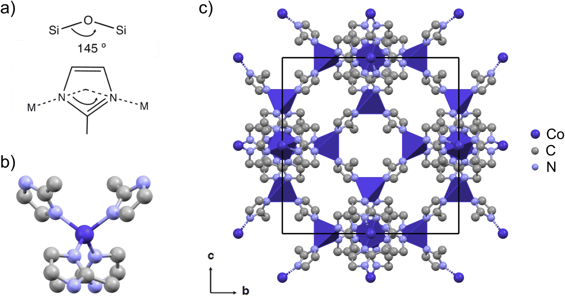 | ||
| Fig. 1 (a) ZIFs are characterized by a zeolite-like angle of the metal-linker-metal connection of 145°, here with 2-methylimidazolate (mIM) as the linker. (b) The tetrahedral coordination of cobalt with linkers in ZIF-67. (c) The cubic crystal structure of ZIF-67 viewed in the b, c-plane (CCDC 671074 (ref. 22)). The unit cell is shown in black, cobalt is shown in dark purple, nitrogen in light blue, and carbon in grey. Hydrogen atoms are omitted for the sake of clarity. The crystal structure is visualized using Mercury.42 | ||
In this work, we investigate the conversion of ZIF-67 to MDNs via pyrolysis. ZIF-67 derived catalysts have been prepared by pyrolysis at various conditions across literature to improve their OER performance.38–41 However, a fundamental understanding of the effect of the pyrolysis conditions on the structure and catalytic activity for electrocatalytic OER is generally lacking. We hypothesize that the catalyst structure and properties are strongly dependent on the pyrolysis conditions. Further, we speculate on whether pyrolysis held for longer durations will generally produce higher performing catalysts, or whether the presence of structural intermediates or disorder could contribute to improving catalytic properties. We address these questions by following the transition from ZIF-67 to MDN from room temperature to 550 °C by in situ X-ray absorption spectroscopy (XAS) and total scattering (TS) followed by pair distribution function (PDF) analysis. In addition, we explore the structure and electrochemical properties of a series of samples resulting from ex situ low-temperature pyrolysis at 550 °C for a variety of time durations, to mimic the conditions of the in situ studies. The structure and electrochemical properties for a MDN pyrolyzed at 650 °C is also considered.
Our findings demonstrate that the best performing catalysts are prepared by pyrolysis at 550 °C for 8 or 12 hours or by heating to 650 °C followed by cooling to room temperature (i.e. without holding the target temperature). The structure of the resulting catalysts can be described as cobalt nanoparticles with bimodal size distributions of 1–2 nm and 7–9 nm, respectively, which are embedded in a nitrogen-doped porous carbon matrix, which assists in preventing agglomeration of the nanoparticles. We propose that improved catalytic performance results from a trade-off among the size of the cobalt particles, the degree of graphitization of the carbon matrix, and the electrochemical active surface area (ECSA). Catalysts prepared at 550 °C without any isotherm maintain the long-range order of the original ZIF-67, and we observe that thermally induced disorder decreases the catalytic activity and stability. Importantly, the structures of the samples prepared ex situ are representative of the different stages of the ZIF-67-to-MDN transition as followed in situ, proceeding from pristine to disordered ZIF-67 followed by a gradual transition from ZIF-67 to metallic cobalt in a carbonaceous matrix. This study therefore demonstrates the feasibility of utilizing in situ methods to screen for suitable phase and order/disorder compositions, which modify catalytic properties.
2 Results and discussion
ZIF-67 was synthesized by a room temperature precipitation reaction in methanol43 and phase-purity was verified through Rietveld refinement of PXRD data (Fig. S1†). Thermogravimetric analysis (TGA) was performed to mimic the pyrolysis process, by heating from room temperature to a target temperature of 550 °C with a heating ramp of 3 °C min−1, resulting in 3 hours of heating. The experiment reveals an onset of decomposition at 400 °C and a mass loss of approx. 33% at 550 °C. When performing TGA with a faster heating ramp of 25 °C min−1, a mass loss of only 2% was found during the 22 min of heating (Fig. S2†), emphasizing the importance of the heating rate on the loss of organic material. However, the same mass loss of 33% was achieved after holding the temperature at 550 °C for an additional 5 minutes, regardless of the heating ramp applied (Fig. S19†).2.1 Following the phase evolution and disorder by in situ pyrolysis
The MOF-to-MDN structural transformation was followed in situ by XAS and TS/PDF analysis, with a focus on the phase evolution and order/disorder transformation. These techniques are highly relevant for the study of crystallographically challenged structures (e.g. amorphous, nanosized, or defect-rich). XAS is an element-specific technique which provides information about the local structure around the absorbing atom and its oxidation state, whereas PDF gives complementary information about all the interatomic correlations in a material, extending over both the local and medium range order.XAS and TS/PDF were used to follow the pyrolysis up to 550 °C with two different heating ramps: XAS with a slower ramp (3 °C min−1) and total scattering with a faster ramp (25 °C min−1). Two different setups were used for heating of the samples at the two beamlines (see experimental section for details). However, the structural evolution during the phase transition is expected to follow the same mechanism.
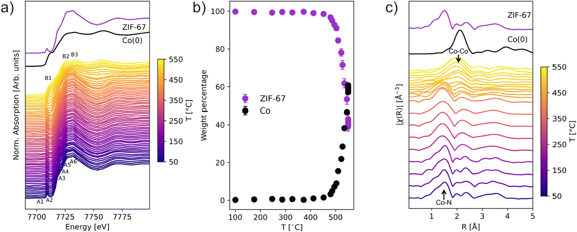 | ||
| Fig. 2 (a) In situ XANES spectra of ZIF-67 during pyrolysis at 3 °C min−1. The spectra are compared with that of an as-synthesized sample of ZIF-67 and a metallic Co(0) foil as reference spectra. Features in the ZIF-67 spectrum are annotated as A1–A6 and features of Co(0) as B1–B3. (b) Phase content evolution during ZIF-67 pyrolysis in weight percentage, based on LCA fitting. Two reference spectra were fitted to the data: ZIF-67 and metallic cobalt. (c) The Fourier transform magnitudes in R-space (not phase corrected) of the in situ EXAFS compared to the spectra of pristine ZIF-67 and metallic cobalt. From room temperature to 450 °C, every ten spectra have been merged, while above 450 °C every two spectra have been merged to capture the rapid changes. | ||
The structural transformation was quantified with linear combination analysis (LCA) with respect to pristine ZIF-67 and metallic Co (Fig. 2b and S3, Table S2†). A gradual change from ZIF-67 to Co is evident above 450 °C. In a span of 100 °C, i.e. slightly more than 33 min (from 450 to 550 °C), the content of ZIF-67 decreased from 98 wt% to 42 wt%. By instead performing LCA fitting against the first and last frame of the data series, the evolution with time is emphasized and indicates that the structural transformation is already initiated below 400 °C (Fig. S4 and S5†). In addition, there is no strong indication of intermediary cobalt oxide or nitride phases (Fig. S6†).
Fourier transforms of the EXAFS region provide complementary information about the local structure around cobalt in real space (Fig. 2c, k-space EXAFS in Fig. S7†). For pristine ZIF-67, the nearest neighbor Co–N gives rise to a peak at 1.5 Å, while the next-nearest neighbor Co–C is observed at 2.0 Å. Around 200 °C a loss of features is observed, and the nearest neighbor peak broadens and downshifts to a slightly smaller distance of 1.4 Å (Fig. S8†). This indicates that structural changes to the framework begin long before the reduction of the Co(II) species to Co(0), and given that no mass losses were observed from TGA (see Fig. S2†) the increased disorder must stem exclusively from structural rearrangement. A gradual decrease in the intensity of the Co–N peak is observed at approx. 450 °C, while a simultaneous increase in intensity at 2.2 Å corroborates the formation of Co–Co interactions (forming metallic cobalt), in agreement with the XANES analysis.
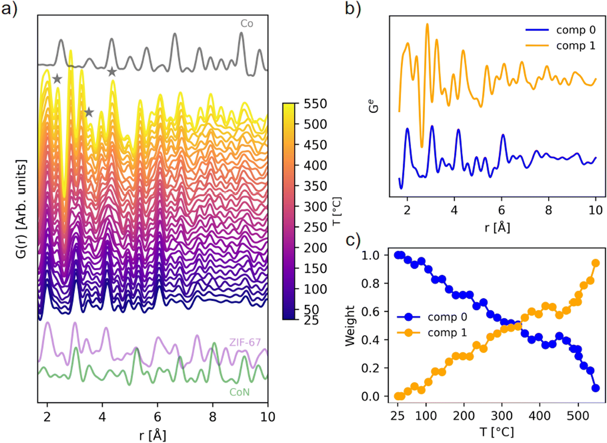 | ||
| Fig. 3 (a) In situ PDF data during pyrolysis of ZIF-67, compared with the calculated PDFs of metallic cobalt in grey (ICSD 76632 (ref. 44)), ZIF-67 in purple (CCDC 671074 (ref. 22)), and cobalt nitride in green (ICSD 79936 (ref. 45)), calculated with PDFgui.46 The emergence of Co–Co peaks is highlighted with grey stars. (b) NMF components, and (c) evolution of the two NMF components with temperature, given as the weight used to recreate the experimental PDFs during the in situ series. | ||
During the total scattering experiment, full decomposition of ZIF-67 is not observed (Fig. 3a and S9†) due to the fast heating ramp, which is in agreement with the TGA measurements (Fig. S2†). Instead, gradual changes are observed, with the system becoming increasingly disordered already at 100–300 °C, i.e. far below the decomposition temperature, corroborated by the EXAFS results. For example, new peaks describing Co–Co interactions start to emerge at approx. 150 °C (Fig. 3a).
The thermally induced structural disorder and phase transformation is further verified through non-negative matrix factorization (NMF) analysis (Fig. 3b and c). Two components are sufficient to describe the structural transformations (Fig. S10 and S11†), where local changes are predominant. The two components correspond to the first frame (component 0) and final frame (component 1) during the pyrolysis data series, i.e. at room temperature and at 550 °C. The evolution is followed through the relative abundance of component 0 and 1, as required to approximate each dataset in the in situ series, referred to as weight (Fig. 3c). A linear change in the sample composition is observed until approx. 400 °C, where the composition stabilizes. This plateau is followed by an increase in the slope after 450 °C. Component 1 shows the emergence of Co–Co peaks below 6 Å as well as an additional peak from Co–N interactions at a lower distance of 1.9 Å (see Fig. S12–S17† for assignment of peaks). Although bond lengths typically increase with temperature, both EXAFS and PDF analyses suggest contraction in the nearest metal to linker bond. This phenomenon has been reported previously during the pyrolysis process of other MOFs, possibly relating to changes in the ligand chemistry or distortions to the framework.20 An intensity increase in the local Co–C peaks is also observed. As the ZIF-67 structure itself has numerous correlations, a complete peak assignment is not included herein.
In summary, the in situ XAS and PDF experiments provide several insights into the pyrolysis process. There is a good agreement between the two techniques, which suggest the formation of metallic cobalt progresses rapidly above 450 °C. No indications of crystalline or amorphous intermediates were observed according to LCA and NMF analyses. Overall, the in situ pyrolysis analyses disclose that transformations of the atomic structure take place even at several hundreds of degrees Celsius below the decomposition point, due to the indications of altered local Co–N, Co–C and Co–Co correlations, despite preservation of long-range order. Such information, which cannot be captured by e.g. conventional TGA or PXRD analysis, is important to acknowledge, given that temperature induced structural disorder may lead to differences in the materials properties.
2.2 Ex situ low-temperature pyrolysis for catalyst preparation
From the in situ investigations, structural transformations are evident below 550 °C, with induced disorder already observed at around 150 °C. Here, we explore the structural and catalytic properties of samples prepared by heating of pristine ZIF-67 under inert conditions, using a tube furnace with a heating ramp of 3 °C min−1, followed by an isothermal stage of different time durations. These samples are denoted ex situ samples herein and are intended to mimic the conditions used in the in situ study presented above, while allowing preparation of larger sample quantities e.g. for catalytic screening. Thus, five pyrolyzed ZIF-67 samples were produced by low-temperature pyrolysis (i.e. below 700 °C): four at 550 °C holding the target temperature for 0, 4, 8, and 12 h, respectively, and one at 650 °C with no subsequent isothermal step (Fig. 4a).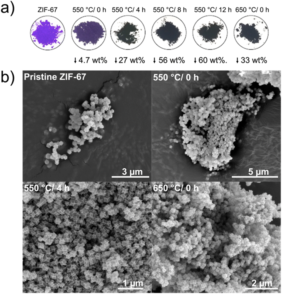 | ||
| Fig. 4 (a) Pictures of pristine and pyrolyzed ZIF-67 powders along with their associated mass loss. (b) SEM images of pristine ZIF-67 (top left), and pyrolyzed ZIF-67 at 550 °C/0 h (top right), 550 °C/4 h (bottom left), and 650 °C/0 h (bottom right). | ||
For the sample heated to 550 °C without any isothermal step (denoted 550 °C/0 h herein), the purple color of the pristine ZIF-67 is mostly preserved, however the final color is less bright than the pristine sample. Under these heating conditions, only a small mass loss of 4.7 wt% was observed (Fig. 4a). From the chemical formula of ZIF-67, it can be estimated that the imidazolate linker comprises 73.3 wt% of the material and cobalt the remaining 26.7 wt%. Thus, by heating to 550 °C/0 h, a large fraction of the organic components is preserved (in agreement with FT-IR analysis, Fig. S21†). The observed mass loss is similar to the expected value from TGA, although slightly lower, which is attributed to the differences in the sample mass load and in the efficiency of heat transport between the tube furnace and the TGA (Fig. S22†). After isothermal heating for 8 and 12 hours, respectively, a black powder results, and the mass loss stabilizes at approx. 60 wt%, as corroborated by the isothermal segment of the TGA (Fig. S18–S22†).
Both pristine and pyrolyzed ZIF-67 exhibit a uniform polyhedral morphology and size distribution, with particle sizes of 200 nm estimated from scanning electron microscopy (SEM) and transmission electron microscopy (TEM) images (Fig. 4b and S23, S24†). After pyrolyzing the MOF for 4 hours at 550 °C, the crystals appear somewhat collapsed, with defined edges and indented facets, which is also observed for the sample pyrolyzed at 650 °C/0 h. Scanning transmission electron microscopy (STEM) combined with energy dispersive X-ray spectroscopy (EDS) confirm that the product of the pyrolysis process comprises cobalt nanoparticles encapsulated in a nitrogen-doped graphitic network, which is a product of the decomposition of the organic components (Fig. S25 and S26†), in agreement with literature.26,29,30,47
The compound surface areas were investigated through nitrogen adsorption–desorption isotherms (Fig. S27†). The Brunauer–Emmett–Teller (BET) specific surface areas based on the gas sorption data (Table S5†) show a loss of porosity as a result of the pyrolysis process, when comparing the pristine ZIF-67 (1272 m2 g−1) to the 550 °C/0 h sample (905 m2 g−1). With the exception of the 550 °C/12 h sample, all samples pyrolyzed at higher temperatures or durations have a surface area below 100 m2 g−1.
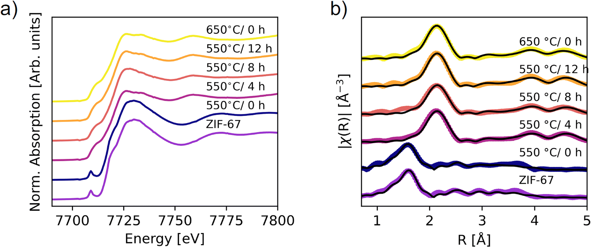 | ||
| Fig. 5 XAS on the ex situ pyrolyzed samples. (a) XANES data. (b) Fourier transform of the EXAFS (not phase corrected). Spectra of the pristine and 550 °C/0 h samples are fitted by using scattering paths calculated from the ZIF-67 structure, while the remaining spectra are fitted with the paths from metallic Co (fcc). The scattering paths were calculated in Artemis.48 | ||
The phase content of the samples was obtained through LCA fitting (Fig. S29–S32, Tables S6 and S7†). The 550 °C/0 h sample is exclusively described by the pristine ZIF-67 phase, while prolonging the pyrolysis durations increase the amount of metallic cobalt. However, the cobalt content is significantly lower than that obtained from the in situ measurement at 550 °C. This difference suggests that the in situ heating process results in faster decomposition, as corroborated by the lower mass loss, which can be explained by differences in heat transport. The final weight fraction of metallic cobalt was 60% in the in situ XAS experiment, compared with 45% after 4 hours of pyrolysis at 550 °C and 56% at 650 °C/0 h. The 650 °C/0 h sample is thus expected to be the best representation of the end-point of the in situ XAS pyrolysis, corroborated by the heat transport differences (Fig. S22†). An improvement in the LCA fits was observed upon including the Co(II) oxide species (Fig. S29, S30 and Table S6†). The ratio of ZIF-67 to cobalt(II) oxide varies marginally between samples prepared at 550 °C/4 h, 8 h, 12 h, and the 650 °C/0 h sample at approx. 15% cobalt(II) oxide. The presence of cobalt(II) oxide in the ex situ samples likely arises due to surface oxidation of the samples after pyrolysis, in contrast to the in situ samples which were kept in inert conditions throughout the entire experiment. The sample compositions for the 550 °C/4 h, 8 h, 12 h, and 650 °C/0 h samples have similar values within 15% difference, which is also expected from the TGA results.
The long-range order of the samples was investigated with PXRD (Fig. 6a), demonstrating that the structure is still preserved when the sample is heated to 550 °C/0 h, which corroborates the ex situ XAS results. Upon longer pyrolysis exposures, a phase transformation occurs, and broader peaks are observed along with a high background signal, attributed to the amorphous carbonaceous matrix. The broad peak at 31° fits well with the (002) reflection of graphite. Two distinct peaks of metallic Co are present, but very broad, signifying small crystallites. Pyrolysis for 8 and 12 hours at 550 °C results in additional diffraction peaks that can be described by the reflections of CoN and/or CoO, in agreement with the proposed presence of Co(II) oxide as derived from the LCA fitting. However, these are not visible as crystalline components for the 550 °C/4 h and 650 °C/0 h samples, which from the TGA alone would be expected to have similar characteristics. To gain insight into the nanostructure of the materials, PDF analysis was employed using total scattering data.
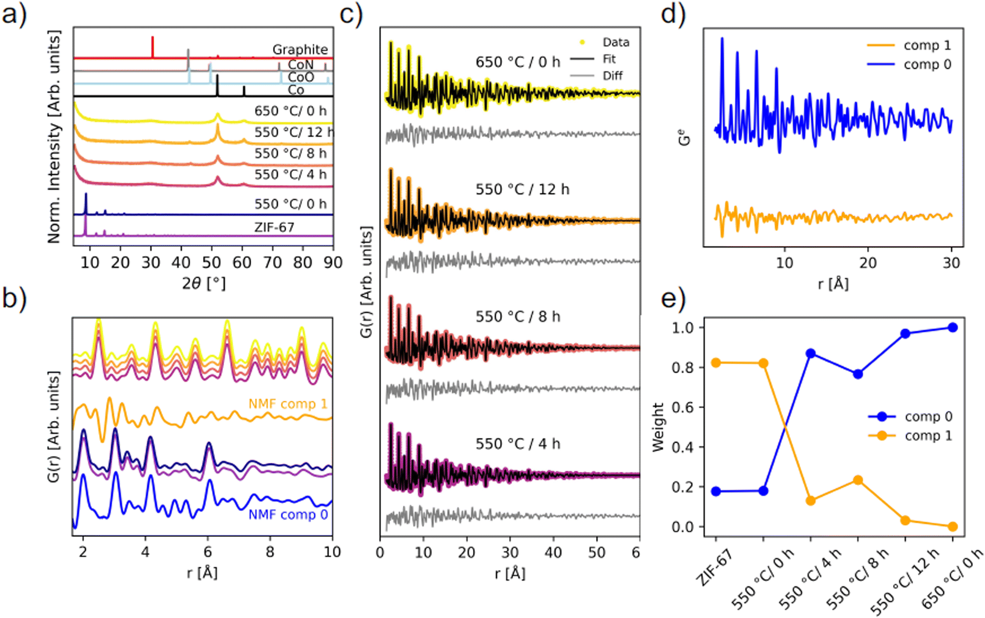 | ||
| Fig. 6 Ex situ scattering experiments. (a) PXRD patterns (λ = 1.79 Å) compared with calculated diffraction patterns of graphite (ICSD 31170 (ref. 49)), CoN (ICSD 79936 (ref. 45)), CoO (ICSD 9865 (ref. 50)), and Co metal (ICSD 76632 (ref. 44)). (b) PDFs of the local structure with identical color coding as in (a), compared with NMF components from the in situ experiment. (c) Two-phase PDF refinements of the four pyrolyzed samples that have converted into metallic Co. (d) NMF components, and (e) the weight of the NMF components used to recreate the experimental PDFs of each of the ex situ samples. | ||
PDFs of the pyrolyzed samples are shown in Fig. 6b and c. A transformation into metallic Co nanoparticles for the samples pyrolyzed at 550 °C for 4 hours or longer is observed in the PDFs, in agreement with EXAFS and PXRD analyses (Fig. 5b and 6a). Locally, the structure of the 550 °C/0 h sample is very similar to the pristine ZIF-67, although more disordered. Especially above 10 Å, features appear less pronounced, which points to a loss of long-range order during the short-term heating process (Fig. S33†). The new correlations observed during the in situ pyrolysis are not detected in the ex situ 550 °C/0 h sample when comparing with NMF comp 1, which represents the final state structure of the in situ series. However, the emergence of the peaks at approx. 2.5 Å and 5 Å, as seen in NMF comp 1, fits well with the first Co–Co correlations observed in the sample pyrolyzed at 550 °C for 4 hours or longer (Fig. 6b). Thus, the in situ PDF results represent intermediary stages in the transition from the pristine ZIF-67, to a similar, but more disordered structure, and finally into metallic cobalt. We conclude that the in situ experiments are representative of the processes used in the production of in-lab scaled-up ex situ samples.
The structure of metallic cobalt has been fitted to the samples which were pyrolyzed for longer durations (Fig. S34 and Table S8†). To account for the envelope function not capturing the shape properly, two phase fits were performed with two Co-phases with different sizes (Fig. 6c and Table S9†). This improved the residual at long distances, but locally, the data is still underdetermined. Variable r-range fits did not resolve the underdetermined peaks (Fig. S35–S38†). This suggests that the local structure (r < 9 Å) is disordered. The two particle sizes of the cobalt in the pyrolyzed samples were determined to be 1.4 nm and 6.5 nm for the 550 °C/4 h sample, 1.4 nm and 7.0 nm for the 550 °C/8 h sample, 1.4 nm and 7.1 nm for the 550 °C/12 h sample, and 1.7 nm and 9.4 nm for the 650 °C/0 h sample. These results suggest that the cobalt particles reach a size of approx. 7 nm, and thereafter stop growing, despite longer pyrolysis times at 550 °C, which supports the hypothesis that the carbon matrix hinders agglomeration, and an equilibrium is reached. These particle sizes are similar to those observed with TEM herein (Fig. S23 and S24†) and also to those previously reported via TEM by others.29 For the 650 °C/0 h sample, larger particles up to 9.4 nm are observed, which could arise due to thermally induced changes in the carbon matrix, which then allow for the formation of larger cobalt particles. These observations suggests that the ex situ pyrolysis conditions are not temperature-independent, despite that the TGA results indicate a temperature independent mass loss and a low activation energy (Fig. S20†).
NMF analysis of the ex situ samples confirms the structural similarity between the pristine ZIF-67 and the sample pyrolyzed at 550 °C/0 h, as they share the same weight of NMF components (Fig. 6d and e). The 550 °C/8 h sample is slightly different from the other ex situ samples pyrolyzed for longer durations at 550 °C or at 650 °C, despite that the 8 and 12 hours samples have similar particle sizes. Thus, the differences are proposed to result from changes of the graphitic C/N matrix. Inclusion of a third component did not noticeably improve the reconstruction errors (Fig. S39†), although a striking similarity in the weight of components is observed compared to the LCA with the CoO phase included (Fig. S30†).
In summary, our findings demonstrate that absolute conditions are difficult to transfer between different setups, and further, that this is important both when using in situ studies to screen for transition temperatures, intermediates, etc. and also when comparing results from different setups for ex situ sample preparation in the lab. Despite this difficulty, it is possible to halt the pyrolysis process at different stages to screen and tune the material properties, for example “trapping” of a sample with increased disorder in the carbon matrix. While TGA captures the slow process of reaching equilibrium, this technique alone cannot be used as a proxy for the catalyst composition. There is a good agreement between the three techniques, i.e. XAS, PXRD, and PDF, and the mechanism of the phase transition observed in situ can describe the pyrolysis of ZIF-67 ex situ. Overall, we find that pyrolysis of ZIF-67 to 550 °C without an additional isothermal heating step (i.e. 550 °C/0 h) induced thermal disorder, whilst preserving the long range order of ZIF-67. After pyrolysis at 550 °C for 4 hours or longer, cobalt nanoparticles are formed. Two particle sizes were found to describe the particles distribution, one of them representing small cobalt clusters of approx. 1–2 nm (corresponding to 7 atoms across the diameter). After pyrolysis at 550 °C for 8 or 12 hours, the cobalt nanoparticles reach a maximum size of 7 nm, and are stabilized within the C/N matrix.
2.3 Electrocatalytic oxygen evolution reaction
In this section, the electrocatalytic oxygen evolution reaction (OER) activity of the ex situ samples is explored. We evaluate the influence of pyrolysis on activity and stability, and attempt to correlate this to the following descriptors: atomic structure, particle size, electrochemical active surface area (ECSA), and the relative cobalt content.Equal amounts of the pyrolyzed samples (by mass) were deposited on carbon paper electrodes with a Nafion binder. Linear sweep voltammetry (LSV) was performed in 1 M KOH(aq) electrolyte with a scan rate of 10 mV s−1 (Fig. 7). Five sweeps were performed (sweep 1–4 in Fig. S40,† sweep 5 Fig. 7a), and an activation of all materials was detected. The electrochemical activity falls within two groups. The activity of the catalysts in the first group is either lower or comparable with that of the pristine ZIF-67, including the 550 °C/0 h and 550 °C/4 h samples. The catalysts in the second group exhibit activity which is significantly higher than that of the pristine ZIF-67, with this group accounting for the catalysts pyrolyzed for longer duration or higher temperature, i.e. 550 °C/8 h, 550 °C/12 h, and 650 °C/0 h.
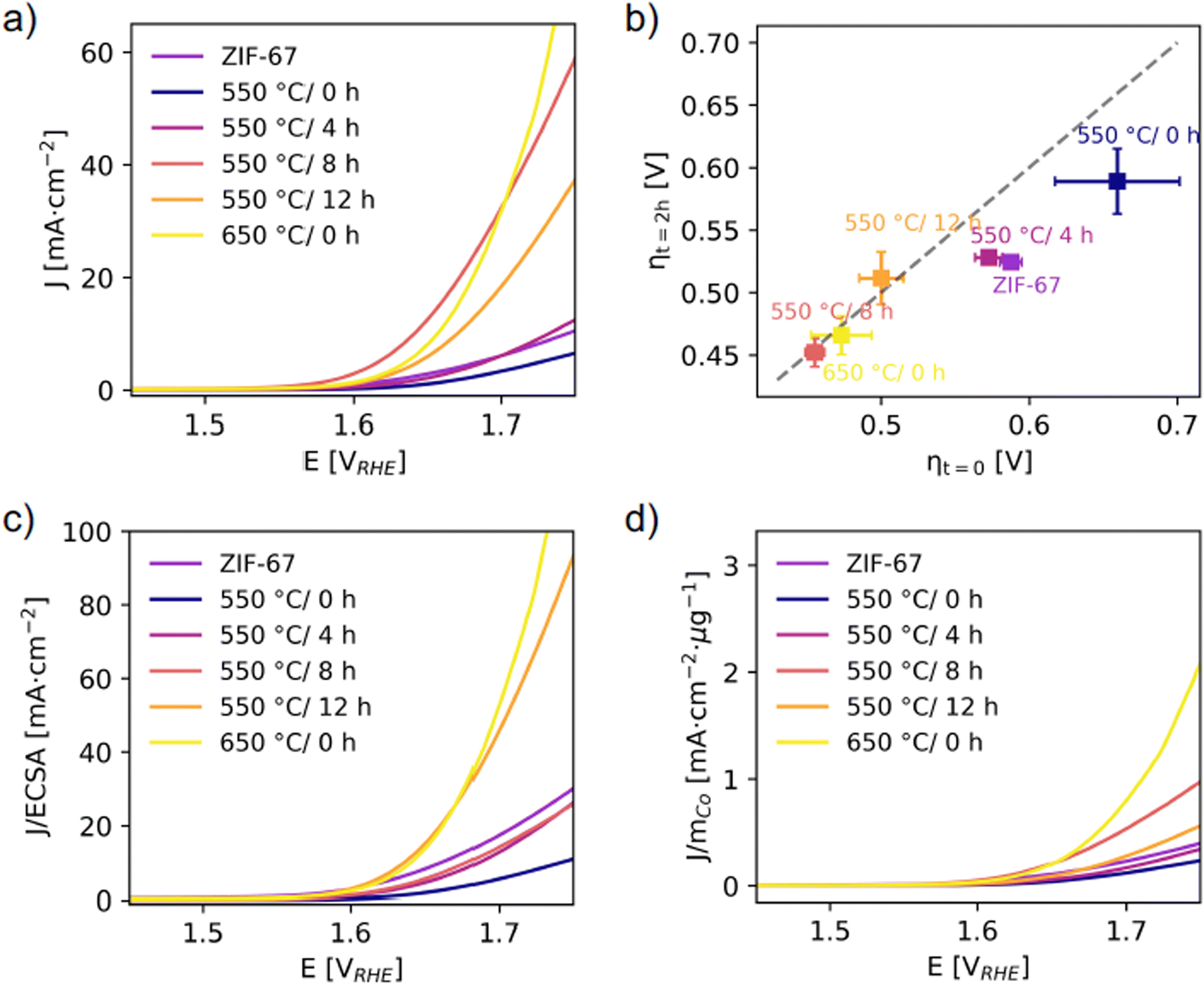 | ||
| Fig. 7 (a) Linear sweep voltammetry with a scan rate of 10 mV s−1. (b) Overpotentials were determined from chronopotentiometry at J = 10 mA cm−2 per geometric area. The x-axis represents the overpotential at time t = 0, as a measure of activity. The y-axis represents the overpotential at time t = 2 h. The diagonal dashed line is the expected response for a stable catalyst, and deviations from this indicate an unstable catalyst.51 (c) LSV responses normalized to the ECSA (from capacitance measurements, see Fig. S43†). (d) LSV responses normalized to the mass of cobalt calculated considering the final Co wt% after pyrolysis under the assumption that the mass loss during pyrolysis is entirely associated to the (volatile) organic linker (Fig. S48†). | ||
In Fig. 7b, the overpotentials are estimated as the electrical bias needed at the anode to draw a current density of J = 10 mA cm−2, and their reliability was checked against other standard methods (Fig. S47†). The worst electrochemical performance is observed for the catalyst pyrolyzed at 550 °C/0 h with an overpotential of ηcurrent = 619 (47) mV. The decrease in electrochemical activity of this catalyst compared to the structurally similar pristine ZIF-67 is attributed to the more disordered local structure (from PDF, Fig. S33†) and also the lesser microporosity (from BET, Fig. S27†).
The activity was significantly improved for catalysts prepared at 550 °C and held at this temperature for 8 and 12 hours, as well as the catalyst pyrolyzed at 650 °C/0 h. For both 550 °C/8 h and 550 °C/12 h, the mass loss was stable (based on TGA, Fig. S22† and 4a) and a stable particle size of approx. 7 nm was reached (based on PDF refinements, Fig. 6c). The main structural differences for the catalyst pyrolyzed at 650 °C/0 h are the larger cobalt nanoparticle size and the higher fraction of organic components remaining (according to the mass loss, Fig. 4a). The 550 °C/8 h catalyst achieves the lowest overpotential of ηcurrent = 416 (3) mV (Fig. S42†). A smaller particle size is generally considered to be beneficial for catalytic applications, but despite that the 550 °C/4 h catalyst contains the smallest cobalt nanoparticles, this catalyst performs worse (with ηcurrent = 516 (12) mV) than the remaining catalysts which were pyrolyzed for longer durations. This is hypothesized to be due to a different nature of the organic components. A higher graphitic degree of the organics-derived matrix will improve the electrical conductivity and electron transport through the catalyst, and is observed in literature with increased pyrolysis temperature/time.29,31 From PXRD (Fig. 6a), the presence of a broad graphite peak is visible for all samples converted to metallic cobalt, however we expect the 550 °C/4 h catalyst to have a poorer graphitic degree compared to both the 650 °C/0 h catalyst and to the 550 °C/8 h and 550 °C/12 h catalysts.
The short-term stability under working conditions was then explored with chronopotentiometry at 10 mA cm−2 for 2 h, which is the current density expected at the anode in a 10% efficient solar water-splitting device under 1 sun illumination.52–54 Representative evolutions of the potential as a function of time for each catalyst are shown in Fig. S45.† The overpotentials required in the beginning, ηt=0, and after 2 hours, ηt=2 h, are reported (Fig. 7b). The pristine ZIF-67, 550 °C/0 h, and 550 °C/4 h catalysts all show a significant decrease in their overpotentials after 2 hours, which corresponds to an activation of the catalyst. The catalysts pyrolyzed for longer durations and at 650 °C/0 h, on the other hand, appear stable under operating conditions. This supports our hypothesis that a higher degree of pyrolysis results in a more stable catalyst.
The activity was also normalized to the ECSA (Fig. 7c), with the ECSA determined from the double layer capacitance of the catalytic surface.55 This was determined by measuring the capacitive current associated with the double-layer charging in a non-Faradic region through cyclic voltammetry at different scan rates (Fig. S43†). The 550 °C/8 h catalyst stands out with the highest double layer capacitance of 0.09 mF compared to 0.01–0.02 mF for the rest. Thus, its high activity can be partially ascribed to surface area effects, i.e. more exposed active sites and a more nanostructured surface. The 550 °C/12 h and 650 °C/0 h catalysts still exhibit the highest normalized activity. When the electrochemical performances of the catalysts are compared with the ECSA metric, it appears even more evident that the samples pyrolyzed at the longest time or at the highest temperature share similar improved performance with respect to the other catalysts. This is in accordance with their structural similarity as highlighted before. Strikingly, the trend in ECSA does not follow the surface area as determined from BET, which is indicative of the catalyst porosity (Fig. S27 and Table S5†). Here the 550 °C/4 h and 550 °C/8 h catalysts stand out as the densest samples with areas of 40 and 42 m2 g−1, which is only half the surface area of the 650 °C/0 h and a third the surface area of the 550 °C/12 h catalyst.
The activity was also normalized to the cobalt mass mCo as determined from the mass loss during pyrolysis under the assumption that the mass loss only comprised the organic linker, while the absolute Co content remained constant (Fig. 7d). A large mass loss during pyrolysis results in a higher relative amount of cobalt in the catalysts. Similar activity and overpotential were determined for the 650 °C/0 h and the 550 °C/8 h catalysts. The 650 °C/0 h catalyst exhibits lower mass loss, and this catalyst exhibits the highest performance in terms of mass activity per cobalt. Thus, from an economic point of view, the 650 °C/0 h sample would be the optimal catalyst in this series.
In conclusion, tuning of pyrolysis conditions can greatly influence the electrocatalytic properties. Literature examples of ZIF-67-derived and -modified catalysts (e.g. nanostructuring,38 multi-heteroatom co-doping,39 interface engineering and heterostructure formation,40 and defect engineering41) have shown good OER performances (see Table S10† for a comparison of electrocatalytic performance of ZIF-67 based and cobalt based catalysts). As many of these modification procedures involve pyrolysis steps, a fundamental understanding of the impact of pyrolysis conditions alone, rather than combined pyrolysis and e.g. chemical modification, is of paramount importance to decouple contributors to catalytic performance.
Several structural characteristics have been explored for a series of ex situ samples, including phase composition, cobalt nanoparticle size, porosity, and ECSA. The question remains, if one of these parameters dominates in controlling the OER properties of pyrolyzed ZIF-67, and if this parameter can potentially be used as a structural indicator for predicting good electrochemical activity of similar materials. To summarize the findings from this structure–activity study: (i) pyrolysis at long time/high temperature gives a more stable sample and better OER performance, (ii) induced disorder in ZIF-67 arising due to short pyrolysis time does not result in defect sites acting as active sites, (iii) there is no direct trend between the BET surface area and the ECSA, (iv) the nanoparticle size is constant for the catalysts pyrolyzed at 550 °C for 8 and 12 hours, and this parameter therefore cannot explain the difference in activity between these two catalysts. Thereby, our findings demonstrate that electrochemical performance is a complex combination of a series of parameters: framework stability obtained through pyrolysis, small Co particles acting as active sites, possibly the degree of graphitization increasing with pyrolysis time/temperature, and exposure of the active sites as indicated by the ECSA. This complex catalyst structure heavily depends on the synthesis, and demonstrates the importance of detailed structural characterization in the description and comparison of pyrolyzed MDNs.
3 Conclusion
In this work, we investigated the structure–activity relationship of a series of pyrolyzed ZIF-67 OER catalysts. Unravelling the structural changes during pyrolysis through a combination of in situ XAS and PDF together with ex situ structural probes reveals the decomposition of ZIF-67 into a MDN consisting of metallic cobalt nanoparticles within a nitrogen-doped graphitic carbon matrix. The onset of decomposition occurs at 450 °C, although structural changes and induced disorder are observed from 150 °C, where the nearest neighbor Co–N bond distance contracts as a result of framework distortions, and the first Co–Co peaks emerges below 6 Å.We conclude that absolute conditions (i.e. pyrolysis temperature and time) are difficult to transfer between setups, both between the two in situ techniques as well as for the ex situ prepared catalysts. Thus, this study materializes the general challenge of comparing results between different setups across literature. Importantly, however, we find that the in situ mechanisms can describe the ex situ pyrolysis, and that the phase transition can be halted at different stages, i.e. as a disordered material with ZIF-67 long range order (550 °C/0 h) and as cobalt nanoparticles with different sizes stabilized by the nitrogen doped carbonaceous matrix (550 °C with 4, 8, 12 hours isotherms and 650 °C/0 h).
The catalytic efficiency of the samples was evaluated by their OER performance. These experiments demonstrate that the best performing catalysts, both in terms of activity and stability, are pyrolyzed at the longest time and highest temperature. These catalysts are best described as cobalt nanoparticles with a bimodal size distribution, which are embedded in a highly graphitized carbonaceous matrix. The best performing catalysts exhibit a compromise between the size of the Co nanoparticles and the degree of graphitization. For comparison, thermally induced disorder in ZIF-67 lowers both the stability and activity in contrast to the pristine material.
Overall, the findings presented in this work pave the way for rational design of catalysts by utilizing pyrolysis at lower temperatures and combining in situ and ex situ structural techniques.
4 Experimental section
All chemicals were purchased from Sigma-Aldrich and used without further purification.4.1 Synthesis of ZIF-67
Crystalline ZIF-67 was synthesized according to the reported procedure:43 Co(NO3)2·6 H2O (1.43 g 7.8 mmol) and 2-methylimidazole (mIM, 3.24 g, 39.5 mmol) were each dissolved in 100 mL methanol. The two solutions were mixed and left to stir for 15 min, and subsequently left for 24 hours without stirring. The product was obtained by centrifugation, washed twice with methanol, and dried in an oven at 70 °C. The product was a fine purple powder.4.2 Synthesis of ex situ pyrolyzed samples
The as-synthesized ZIF-67 was pyrolyzed in a Nabertherm tube furnace with a heating ramp of 3 °C min−1 with a 0.1 L min−1 N2 flow. Five samples were prepared: one at 550 °C with no further heating at the target temperature (550 °C/0 h), three at 550 °C with isothermal heating at the target temperature for several hours (4, 8, and 12 hours) to give the 550 °C/4 h, 550 °C/8 h and 550 °C/12 h samples, respectively, and one at 650 °C with no further heating (650 °C/0 h). The samples were left to cool naturally in the oven.4.3 X-ray absorption spectroscopy
In situ XAS was performed at the K edge of cobalt (7709 eV) in transmission mode at the B18 beamline at the Diamond Light Source in Oxford, UK.56 A capillary furnace setup, provided by the beamline, was used. To obtain a suitable absorption edge step, powder of ZIF-67 was diluted with boron nitride and pressed to a pellet. The powder composition was estimated using the software XAFSmass.57 A part of the pellet was inserted into a 3 mm quartz capillary, which was connected to the beamline mass flow controllers using Swagelok tubing, and the sample was purged by a nitrogen flow of 100 mL min−1. The sample was heated from room temperature to 550 °C by indirect resistance heating at a heating ramp of 3 °C min−1. Transmission spectra covering both the X-ray absorption near-edge structure (XANES) and the extended X-ray absorption fine structure (EXAFS) region (200 eV below the edge to 850 eV above the edge) were collected in continuous scan mode with an acquisition time of approx. 90 seconds per spectrum. The X-ray energy was selected using a double crystal Si(111) monochromator, and spectra on a cobalt metal foil were measured simultaneously for energy calibration.Data on samples prepared ex situ were measured at the Balder beamline at the MAX-IV laboratory.58 The spectra were collected in transmission using a double crystal Si(311) monochromator, with acquisition times of approx. 2 min, thereafter a new position on the pellet was chosen, to minimize the risk of radiation damage. After data reduction, approx. 8 spectra were merged for better statistics.
XAS data were processed in Athena, and the data fitting was conducted in Artemis.48 Linear combination analysis (LCA) fitting of XANES spectra (both in situ and ex situ) was carried out in Athena over the energy range −15 to +30 eV in regard to E0. The phase content was restrained to values between 0 and 1, and the sum of the phases to 1. To obtain better statistics, in situ data were merged, with every ten spectra below 450 °C where minimal changes were observed, and every second spectra above 450 °C to present data with a good time resolution. This procedure results in an uncertainty on the temperature below 450 °C of 45 °C and an uncertainty of 9 °C above.
4.4 X-ray total scattering and pair distribution function analysis
The in situ total scattering data were collected at the P21.1 (λ = 0.1204 Å) beamline, while the ex situ data were measured at the P02.1 (ref. 59) (λ = 0.2073 Å) beamline, both at PETRA III at the Deutsches Elektronen-Synchrotron (DESY) in Hamburg, Germany. Data were acquired on an amorphous silicon two-dimensional (2D) flat panel PerkinElmer XRD1621 detector (40 × 40 cm2, pixel size of 200 × 200 μm2) in full ring configuration with an angular resolution (Qmax) of 25.5 Å−1 at P21.1 and on a VAREX XRD 4343CT detector (43 × 43 cm2, pixel size of 150 × 150 μm2) with a Qmax of 19.7 Å−1 at P02.1.For the in situ pyrolysis, a custom-built capillary setup previously described60 was used. To achieve a high transmission of X-rays, the ZIF-67 powder was packed in fused silica capillaries with an inner diameter of 0.7 mm and an outer diameter of 0.85 mm. The capillary was connected to the reactor using graphite ferrules and Swagelok fittings, allowing a flow of argon gas with 100 mL min−1. A heating ramp of 25 °C min−1 was applied, using a hot air blower. As it was not possible to monitor the temperature inside the capillary during the pyrolysis experiment, a temperature calibration was performed prior to the experiment with a thermocouple. The reason for not repeating the experiment with a ramp of 3 °C min−1 (matching the XAS experiment) was time restrictions at the synchrotron facilities. It is anticipated that at 3 °C min−1 and at 25 °C min−1, the mechanism of the structural evolution will be the same, however the onset temperature of the phase transition as well as the absolute extent of the transition will vary between the experiments.
Ex situ samples were measured in five blocks of 60 s dark followed by 5 × 60 s of exposure, thus a total measuring time of 5 min per sample. Samples were spun during the measurement.
The azimuthal integration and calibrations were performed with the Dioptas61 and pyFAI (V0.20)62 software. PDFgetX3![[thin space (1/6-em)]](https://www.rsc.org/images/entities/char_2009.gif) 63 and xPDFsuite64 were used for subtraction of the integrated intensities of an empty capillary and to obtain S(Q), F(Q), and G(r) functions. A Q-range of 0.1–17.5 Å−1 was used for the Fourier transformation of the in situ P21.1 data, and 0.1–19.2 Å−1 for the ex situ data. In all cases, an Rpoly = 1.1 was applied. Data were collected on CeO2 and LaB6 standards to calibrate the distance from sample to detector, in addition to the instrumental Qbroad and Qdamp parameters. Data modelling was performed with DiffPy-CMI65 and NMF analysis with the nmfMapping application on the PDFitc platform.66,67
63 and xPDFsuite64 were used for subtraction of the integrated intensities of an empty capillary and to obtain S(Q), F(Q), and G(r) functions. A Q-range of 0.1–17.5 Å−1 was used for the Fourier transformation of the in situ P21.1 data, and 0.1–19.2 Å−1 for the ex situ data. In all cases, an Rpoly = 1.1 was applied. Data were collected on CeO2 and LaB6 standards to calibrate the distance from sample to detector, in addition to the instrumental Qbroad and Qdamp parameters. Data modelling was performed with DiffPy-CMI65 and NMF analysis with the nmfMapping application on the PDFitc platform.66,67
4.5 Powder X-ray diffraction
PXRD data were measured at room temperature on a Rigaku Smartlab diffractometer using Co Kα1 and Co Kα2 radiation (λ = 1.79 Å). Parallel beam optics were used, and data were collected in an angular 2θ range of 5–90° on a D/TEX 250 strip detector. Rietveld refinement of the pristine ZIF-67 data was performed using the FullProf Software68 to confirm the phase purity of the sample.4.6 Scanning electron microscopy
Images were collected on a FEI-Nova Nano SEM 600 scanning electron microscope under high-vacuum conditions in field immersion mode through a lens detector (TLD). An accelerating voltage of 5.00 kV and a spot size of 4.0 were utilized. Samples were immobilized on aluminum supports with conductive carbon tape and coated with a 7 nm Pt layer using a Leica EM SCD 500.4.7 Electrochemical OER
| E(VRHE) = EAg/AgCl0(VNHE) + 0.059 × pH |
Linear sweep voltammetry (LSV) was performed with a scan rate of 10 mV s−1. The activity was compared with that of the reference catalyst, i.e. IrO2 and a blank carbon paper. The polarization curves were iR corrected, with a typical ohmic loss of 3.3 ± 0.3 Ω. Chronopotentiometry was performed at 10 mA cm−2 for 2 hours. The electrochemically active surface area (ECSA) was determined before and after chronopotentiometry for 2 hours. It was evaluated through cyclic voltammetry in the non-faradaic region at different scan rates to determine the double layer capacitance (CDL). The ECSA of the sample was then calculated according to the following equation:
| ECSA = CDL/CS |
Conflicts of interest
There are no conflicts of interest to declare.Acknowledgements
We gratefully acknowledge funding from the Carlsberg Foundation (CF19-0585 and CF14-0506) the Danish National Research Foundation (Carbon Dioxide Activation Center, DNRF 118), and DanScatt. Affiliation with Center for Integrated Materials research (iMAT) at Aarhus University is acknowledged. Work in the Billinge group was supported by the U.S. National Science Foundation through grant DMREF-1922234. We acknowledge DESY (Hamburg, Germany), a member of the Helmholtz Association HGF, for the provision of experimental facilities. Parts of this research were carried out at the PETRA III beamline P02.1 and P21.1. We would like to thank Ann-Christin Dippel for assistance in using beamline P21.1. Beamtimes were allocated by an in-house contingent. Dr Matthias S. Hvid is thanked for assistance during data collection at DESY. Likewise, we acknowledge the Diamond Light Source (UK) for beamtime on B18 (proposal number SP22410), and Giannantonio Cibin is kindly acknowledged for his support at the beamline. We acknowledge the MAX IV Laboratory for time on the Balder beamline under Proposal 20190489. Research conducted at MAX IV, a Swedish national user facility, is supported by the Swedish Research council under contract 2018-07152, the Swedish Governmental Agency for Innovation Systems under contract 2018-04969, and Formas under contract 2019-02496. Beamline scientist Justus Just is thanked for his assistance at the beamline.References
- L. Oar-Arteta, T. Wezendonk, X. H. Sun, F. Kapteijn and J. Gascon, Mater. Chem. Front., 2017, 1, 1709–1745 RSC.
- X. F. Lu, Y. J. Fang, D. Y. Luan and X. W. D. Lou, Nano Lett., 2021, 21, 1555–1565 CrossRef CAS PubMed.
- S. Frank, E. S. Grape, E. D. Bojesen, R. Larsen, P. Lamagni, J. Catalano, A. K. Inge and N. Lock, J. Mater. Chem. A, 2021, 9, 26298–26310 RSC.
- M. L. Ding, X. C. Cai and H. L. Jiang, Chem. Sci., 2019, 10, 10209–10230 RSC.
- A. J. Howarth, Y. Y. Liu, P. Li, Z. Y. Li, T. C. Wang, J. Hupp and O. K. Farha, Nat. Rev. Mater., 2016, 1, 15018 CrossRef CAS.
- K. J. Lee, J. H. Lee, S. Jeoung and H. R. Moone, Acc. Chem. Res., 2017, 50, 2684–2692 CrossRef CAS PubMed.
- Y. H. Song, X. Li, L. L. Sun and L. Wang, RSC Adv., 2015, 5, 7267–7279 RSC.
- D. L. Huang, G. F. Wang, M. Cheng, G. X. Zhang, S. Chen, Y. Liu, Z. H. Li, W. J. Xue, L. Lei and R. H. Xiao, Chem. Eng. J., 2021, 421, 127817 CrossRef CAS.
- J. Z. Zhang, B. An, Y. H. Hong, Y. P. Meng, X. F. Hu, C. Wang, J. D. Lin, W. B. Lin and Y. Wang, Mater. Chem. Front., 2017, 1, 2405–2409 RSC.
- T. A. Wezendonk, V. P. Santos, M. A. Nasalevich, Q. S. E. Warringa, A. I. Dugulan, A. Chojecki, A. C. J. Koeken, M. Ruitenbeek, G. Meima, H. U. Islam, G. Sankar, M. Makkee, F. Kapteijn and J. Gascon, ACS Catal., 2016, 6, 3236–3247 CrossRef CAS.
- K. Nakatsuka, T. Yoshii, Y. Kuwahara, K. Mori and H. Yamashita, Chem.–Euro. J., 2018, 24, 898–905 CrossRef CAS PubMed.
- S. H. Wang, J. Teng, Y. Y. Xie, Z. W. Wei, Y. A. Fan, J. J. Jiang, H. P. Wang, H. G. Liu, D. W. Wang and C. Y. Su, J. Mater. Chem. A, 2019, 7, 4036–4046 RSC.
- Z. H. Y. Chen, Z. J. Chen, O. K. Farha and K. W. Chapman, J. Am. Chem. Soc., 2021, 143, 8976–8980 CrossRef CAS PubMed.
- S. H. Wang, M. Q. Chen, Y. Y. Xie, Y. N. Fan, D. W. Wang, J. J. Jiang, Y. G. Li, H. Grutzmacher and C. Y. Su, Small, 2016, 12, 2365–2375 CrossRef CAS PubMed.
- Y. L. Wang, J. Wang, D. D. Wei and M. G. Li, ACS Appl. Mater. Interfaces, 2019, 11, 35755–35763 CrossRef CAS PubMed.
- Q. Ren, H. Wang, X. F. Lu, Y. X. Tong and G. R. Li, Adv. Sci., 2018, 5, 1700515 CrossRef PubMed.
- J. L. Liu, D. D. Zhu, C. X. Guo, A. Vasileff and S. Z. Qiao, Adv. Energy Mater., 2017, 7, 1700518 CrossRef.
- A. Radwan, H. H. Jin, D. P. He and S. C. Mu, Nano-Micro Lett., 2021, 13, 132 CrossRef CAS PubMed.
- K. A. Adegoke and N. W. Maxakato, Mater. Today Energy, 2021, 21, 100816 CrossRef CAS.
- N. Prinz, S. Strubbe, M. Bauer and M. Zobel, New J. Chem., 2023, 47, 11623–11635 RSC.
- M. Folkjær, L. F. Lundegaard, H. S. Jeppesen, M. J. Marks, M. S. Hvid, S. Frank, G. Cibin and N. Lock, Dalton Trans., 2022, 51, 10740–10750 RSC.
- R. Banerjee, A. Phan, B. Wang, C. Knobler, H. Furukawa, M. O'Keeffe and O. M. Yaghi, Science, 2008, 319, 939–943 CrossRef CAS PubMed.
- B. Li, K. Igawa, J. W. Chai, Y. Chen, Y. Wang, D. W. Fam, N. N. Tham, T. An, T. Konno, A. Q. Sng, Z. L. Liu, H. Zhang and Y. Zong, Energy Storage Mater., 2020, 25, 137–144 CrossRef.
- X. F. He, L. B. Chang, P. F. Han, K. K. Li, H. J. Wu, Y. Tang, F. Gao, Y. T. Zhang and A. N. Zhou, Colloids Surf., A, 2023, 663, 130988 CrossRef CAS.
- Y. X. Luo, M. Wen, J. Zhou, Q. S. Wu, G. F. Wei and Y. Q. Fu, Small, 2023, 19, 2302925 CrossRef CAS PubMed.
- W. Xia, J. Zhu, W. Guo, L. An, D. Xia and R. Zou, J. Mater. Chem. A, 2014, 2, 11525–12076 RSC.
- Y. Gao, Z. Han, S. Hong, T. Wu, X. Li, J. Qiu and Z. Sun, ACS Appl. Energy Mater., 2019, 2, 6071–6077 CrossRef CAS.
- H. S. Jadhav, H. A. Bandal, S. Ramakrishna and H. Kim, Adv. Mater., 2022, 34, 2107072 CrossRef CAS PubMed.
- Z. Wang, X. Ke, K. Zhou, X. Xu, Y. Jin, H. Wang and M. Sui, J. Mater. Chem. A, 2021, 9, 18515–18525 RSC.
- Y. Zhou, X. Deng, H. N. Xing, H. Y. Zhao, Y. B. Liu, L. S. Guo, J. Feng, W. Feng, Y. Zong, X. H. Zhu, X. H. Li, Y. Peng and X. L. Zheng, Nano Res., 2022, 15, 6819–6830 CrossRef CAS.
- B. Y. Xia, Y. Yan, N. Li, H. B. Wu, X. W. Lou and X. Wang, Nat. Energy, 2016, 1, 15006 CrossRef CAS.
- M. Y. Yin, Y. Y. Zhang, Z. F. Bian, Y. F. Bu, X. Y. Chen, T. L. Zhu, Z. G. Wang, J. Wang, S. Kawi and Q. Zhong, Electrochim. Acta, 2019, 299, 610–617 CrossRef CAS.
- J. Z. Li, H. G. Zhang, W. Samarakoon, W. T. Shan, D. A. Cullen, S. Karakalos, M. J. Chen, D. M. Gu, K. L. More, G. F. Wang, Z. X. Feng, Z. B. Wang and G. Wu, Angew. Chem., Int. Ed., 2019, 58, 18971–18980 CrossRef CAS PubMed.
- X. Y. Li, Q. Q. Jiang, S. Dou, L. B. Deng, J. Huo and S. Y. Wang, J. Mater. Chem. A, 2016, 4, 15836–15840 RSC.
- R. M. Zhu, J. W. Ding, J. P. Yang, H. Pang, Q. Xu, D. L. Zhang and P. Braunstein, ACS Appl. Mater. Interfaces, 2020, 12, 25037–25041 CrossRef CAS PubMed.
- A. G. Dymerska, B. Środa, B. Zielińska and E. Mijowska, Mater. Des., 2023, 226, 111637 CrossRef CAS.
- X. Q. Wang, Z. Chen, X. Y. Zhao, T. Yao, W. X. Chen, R. You, C. M. Zhao, G. Wu, J. Wang, W. X. Huang, J. L. Yang, X. Hong, S. Q. Wei, Y. Wu and Y. D. Li, Angew. Chem., Int. Ed., 2018, 57, 1944–1948 CrossRef CAS PubMed.
- G. Jia, W. Zhang, G. Z. Fan, Z. S. Li, D. G. Fu, W. C. Hao, C. W. Yuan and Z. G. Zou, Angew. Chem., Int. Ed., 2017, 56, 13781–13785 CrossRef CAS PubMed.
- S. H. Liu, Z. Y. Wang, S. Zhou, F. J. Yu, M. Z. Yu, C. Y. Chiang, W. Z. Zhou, J. J. Zhao and J. S. Qiu, Adv. Mater., 2017, 29, 1700874 CrossRef PubMed.
- X. H. Luo, Q. L. Zhou, S. Du, J. Li, J. W. Zhong, X. L. Deng and Y. L. Liu, ACS Appl. Mater. Interfaces, 2018, 10, 22291–22302 CrossRef CAS PubMed.
- Q. Q. Zha, W. Y. Xu, X. L. Li and Y. H. Ni, Dalton Trans., 2019, 48, 12127–12136 RSC.
- C. F. Macrae, I. Sovago, S. J. Cottrell, P. T. A. Galek, P. McCabe, E. Pidcock, M. Platings, G. P. Shields, J. S. Stevens, M. Towler and P. A. Wood, J. Appl. Crystallogr., 2020, 53, 226–235 CrossRef CAS PubMed.
- B. Qiu, C. Yang, W. Guo, Y. Xu, Z. Liang, D. Ma and R. Zou, J. Mater. Chem. A, 2017, 5, 8081–8086 RSC.
- A. Taylor and R. W. Floyd, Acta Crystallogr., 1950, 3, 285–289 CrossRef CAS.
- K. Suzuki, T. Kaneko, H. Yoshida, H. Morita and H. Fujimori, J. Alloys Compd., 1995, 224, 232–236 CrossRef CAS.
- C. L. Farrow, P. Juhas, J. W. Liu, D. Bryndin, E. S. Bozin, J. Bloch, T. Proffen and S. J. L. Billinge, J. Phys.: Condens. Matter, 2007, 19, 335219 CrossRef CAS PubMed.
- B. You, N. Jiang, M. Sheng, W. S. Drisdell, J. Yano and Y. Sun, ACS Catal., 2015, 5, 7068–7076 CrossRef CAS.
- B. Ravel and M. Newville, J. Synchrotron Radiat., 2005, 12, 537–541 CrossRef CAS PubMed.
- O. Hassel and H. Mark, Z. Phys., 1924, 25, 317–337 CrossRef CAS.
- S. Sasaki, K. Fujino, E. Tak and Y. Uchi, Proc. Jpn. Acad., Ser. B, Phys. Biol. Sci., 1979, 55, 43–48 CrossRef CAS.
- C. C. L. McCrory, S. H. Jung, J. C. Peters and T. F. Jaramillo, J. Am. Chem. Soc., 2013, 135, 16977–16987 CrossRef CAS PubMed.
- M. G. Walter, E. L. Warren, J. R. McKone, S. W. Boettcher, Q. Mi, E. A. Santori and N. S. Lewis, Chem. Rev., 2010, 110, 6446–6473 CrossRef CAS PubMed.
- M. F. Weber and M. J. Dignam, J. Electrochem. Soc., 1984, 131, 1258–1265 CrossRef CAS.
- Y. Matsumoto and E. Sato, Mater. Chem. Phys., 1986, 14, 397–426 CrossRef CAS.
- S. Trasatti and O. A. Petrii, Pure Appl. Chem., 1991, 63, 711–734 CrossRef CAS.
- A. J. Dent, G. Cibin, S. Ramos, A. D. Smith, S. M. Scott, L. Varandas, M. R. Pearson, N. A. Krumpa, C. P. Jones and P. E. Robbins, J. Phys.: Conf. Ser., 2009, 190, 012039 CrossRef.
- K. Klementiev and R. Chernikov, J. Phys.: Conf. Ser., 2016, 712, 012008 CrossRef.
- K. Klementiev, K. Norén, S. Carlson, K. G. V. S. Clauss and I. Persson, J. Phys.: Conf. Ser., 2016, 712, 012023 CrossRef.
- A. C. Dippel, H. P. Liermann, J. T. Delitz, P. Walter, H. Schulte-Schrepping, O. H. Seeck and H. Franz, J. Synchrotron Radiat., 2015, 22, 675–687 CrossRef CAS PubMed.
- J. Becker, M. Bremholm, C. Tyrsted, B. Pauw, K. M. O. Jensen, J. Eltzholt, M. Christensen and B. B. Iversen, J. Appl. Crystallogr., 2010, 43, 729–736 CrossRef CAS.
- C. Prescher and V. B. Prakapenka, High Pressure Res., 2015, 35, 223–230 CrossRef CAS.
- J. Kieffer, V. Valls, N. Blanc and C. Hennig, J. Synchrotron Radiat., 2020, 27, 558–566 CrossRef CAS PubMed.
- P. Juhas, T. Davis, C. L. Farrow and S. J. L. Billinge, J. Appl. Crystallogr., 2013, 46, 560–566 CrossRef CAS.
- X. Yang, P. Juhas, C. L. Farrow and S. J. Billinge, arXiv, preprint, arXiv:1402.3163, 2014, DOI:10.48550/arXiv.1402.3163.
- P. Juhas, C. L. Farrow, X. H. Yang, K. R. Knox and S. J. L. Billinge, Acta Crystallogr., Sect. A: Found. Adv., 2015, 71, 562–568 CrossRef PubMed.
- Z. Thatcher, C. H. Liu, L. Yang, B. C. McBride, G. T. Tran, A. Wustrow, M. A. Karlsen, J. R. Neilson, D. B. Ravnsbaek and S. J. L. Billinge, Acta Crystallogr., Sect. A: Found. Adv., 2022, 78, 242–248 CrossRef CAS PubMed.
- L. Yang, E. A. Culbertson, N. K. Thomas, H. T. Vuong, E. T. S. Kjaer, K. M. O. Jensen, M. G. Tucker and S. J. L. Billinge, Acta Crystallogr., Sect. A: Found. Adv., 2021, 77, 2–6 CrossRef CAS PubMed.
- J. Rodríguez-Carvajal, Phys. B, 1993, 192, 55–69 CrossRef.
Footnote |
| † Electronic supplementary information (ESI) available. See DOI: https://doi.org/10.1039/d3ta05293a |
| This journal is © The Royal Society of Chemistry 2024 |