 Open Access Article
Comparing a covalently linked BODIPY–pyrene system versus the corresponding physical mixture as chromophores in luminescent solar concentrators†
Massimiliano
Cordaro
ab,
Giulia
Neri
 a,
Anna
Piperno
a,
Ambra M.
Cancelliere
a,
Antonio
Santoro
a,
Scolastica
Serroni
a,
Francesco
Nastasi
ac and
Antonino
Arrigo
a,
Anna
Piperno
a,
Ambra M.
Cancelliere
a,
Antonio
Santoro
a,
Scolastica
Serroni
a,
Francesco
Nastasi
ac and
Antonino
Arrigo
 *ac
*ac
aDepartment of Chemical, Biological, Pharmaceutical and Environmental Sciences, University of Messina, Viale Ferdinando Stagno d’Alcontres, 31, 98166 Messina, Italy
bITAE-CNR, Via Salita S. Lucia Sopra Contesse 5, Messina, Italy
cInteruniversitary Research Center for Artificial Photosynthesis (Solar Chem, Messina Node), V. F. Stagno d’Alcontres 31, 98166 Messina, Italy
First published on 9th April 2024
Abstract
Luminescent solar concentrators (LSCs) appear as an attractive solution to extend the application of photovoltaic panels by installing them “invisibly” in urban architectures. Many researchers are working on boosting the photovoltaic performances of LSCs, and an appealing strategy is to involve a multichromophoric system where Förster resonance energy transfer (FRET) occurs. To investigate the role of the energy donor, which is crucial in FRET processes inside LSCs, we designed a light-harvesting antenna composed of a highly emissive donor, such as pyrene, covalently connected to a BODIPY unit as an energy acceptor. Such an antenna was used as the chromophore to fabricate a LSC and the photovoltaic performance of the device was compared with that of the LSC based on a physical mixture of BODIPY and pyrene not covalently bonded. The results indicate that the LSC based on the antenna system has a lower optical efficiency than the LSC containing the physical mixture. Such a conclusion highlights that designing an antenna system composed of a highly luminescent species as the energy donor (e.g. pyrene, in this case) could not improve the LSC photovoltaic performances compared to the LSC based on the physical mixture of the separated chromophores.
Introduction
Over the recent years, renewable energies are progressing as valuable options to replace conventional energy sources based on fossil fuels, which are causing climate and environmental issues on the planet.1–5 Among the existing sustainable technologies, such as wind, biomass or hydroelectric, solar energy conversion appears to be one of the most attractive considering that during one hour the Sun provides to the Earth's surface a quantity of energy approximately equal to the energy consumed in the globe over one year.6,7 In the last few decades, various solar energy conversion devices have been developed, including photovoltaic (PV) panels which achieve outstanding conversion efficiencies. Although the use of photovoltaics has been recently diffused globally, nowadays less than 1% of our total energy consumption is generated by this technology;8 such an assessment suggests that the installation of more PV panels is necessary, but on the other hand, this would include covering some habitable landscapes, implying environmental and strategic consequences.9 A possible solution to extend the PV applications in large areas is the development of building integrated photovoltaics (BIPVs), where energy-generating technologies are installed into architectural structures.10 In this context, luminescent solar concentrators (LSC), proposed for the first time in 1973,11 appear as a praiseworthy solution. LSCs are transparent plastic or glass materials containing luminophores which absorb a portion of the solar spectrum and emit photons at lower energy. Due to the high refraction index of the LSC matrix which causes a total internal reflection phenomenon, the luminescence is waveguided to the edges of the material, where photovoltaic panels are mounted and convert emitted photons into electrical energy.12–15 LSCs can be applied in a series of urban architectures, for instance in noise barriers,16–18 greenhouses,19 and bus stops,20 or used as windows, thus “invisibly” incorporating the PV panels in the buildings, without altering the indoor illumination and helping the diffusion of photovoltaic technologies on large areas.21Various luminophores have been tested inside LSCs, such as quantum dots (QDs) or molecules.22–25 Luminescent QDs are nanomaterials exhibiting a notable photo-stability in liquid and solid states and a large Stokes-shift which avoids emission losses due to re-absorption phenomena.26,27 Nevertheless, the highest values of power conversion efficiencies for a LSC-PV coupled system have been reached by using luminescent molecular dyes, like the case of the record value obtained by using up-conversion dual panel LSCs containing a porphin–palladium complex and a perylene unit.28,29
Although a large number of fascinating chromophores have been explored for LSC applications, using a single chromophoric species leads to a material capable of absorbing only a limited portion of the solar spectrum. To overcome such a limit, an appealing approach is to construct a covalently linked multi-chromophoric system composed of a chromophore (i.e. donor) which absorbs light and funnels the excitation energy to a luminophore (i.e. acceptor) which emits photons.30 Such systems behave as a light-harvesting antenna where Förster resonance energy transfer (FRET) processes occur.
The concept of FRET and an antenna system entrapped in the LSC matrix was introduced in 1977,31 with the goal to fabricate a LSC capable of absorbing a wider part of the solar spectrum and in parallel to improve the optical properties of the material and mitigate the energy losses in the LSC.32–36
In the last few years, several research groups studied the energy transfer process as a possible strategy to boost the efficiency of LSC-PV devices, and the results highlighted that the selection of an appropriate energy donor and an acceptor is a crucial feature for designing an efficient antenna system.37–39 In particular, it is well acknowledged that an appropriate donor must have a strong absorption in the visible region; however, less attention is typically dedicated to its luminescence properties.
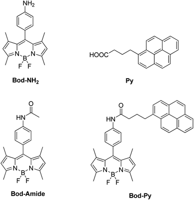
Focusing specifically on the role of the donor in FRET, here we report on a LSC based on a series of BODIPY (difluoroBOronDIPYrromethene) derivatives, including a species (named Bod-Py, see Fig. 1) where a pyrene unit is covalently linked to the BODIPY “core”, through an amide bond of aliphatic and aromatic spacers. The excited singlet state of pyrene lies at a higher energy compared to the excited singlet state of BODIPY, which favours the BODIPY–pyrene system to behave like an antenna, where the pyrene unit plays the role of the energy donor and the BODIPY moiety, the role of the energy acceptor and emitter. BODIPY and pyrene derivatives have impressive photophysical properties, such as strong visible absorption and remarkable luminescence quantum yield, which make such chromophores to be employed in a plethora of applications,40–45 including solar energy conversion.46,47
Here, the photophysical investigations on the synthetized species and the photovoltaic performances of LSCs are presented. In particular, the optical efficiency of the LSC based on Bod-Py was compared with that of the LSC based on the physical mixture of the chromophores that are notcovalently connected, spotlighting the effect of choosing a highly luminescent species (i.e. pyrene) as the energy donor in these systems.
Results and discussion
Synthesis and photochemical characterization in solution
The molecular species Bod-NH2 and Bod-Amide (Fig. 1), used as models, were synthesized according to known procedures.48Bod-Py was synthesized by a coupling reaction between Bod-NH2 and commercial 1-pyrenebutyric acid Py. Experimental data are provided in the ESI.†The steady state photophysical properties of these species have been studied in dichloromethane (DCM) dilute solutions (∼10−6 M) and are summarized in Table 1 and illustrated in Fig. 2 (and the ESI†).
| ε (M−1 cm−1) | λ max (nm) absorption | λ max (nm) emission | τ (ns) | φ in DCM | ||||
|---|---|---|---|---|---|---|---|---|
| In DCM | In LSC | In DCM | In LSC | In DCM | In LSC | |||
a Band maximum or lifetime related to the pyrene unit.
b Band maximum or lifetime related to the BODIPY unit.
c The mixture composed of Bod-Amide and Py in a ratio of 1![[thin space (1/6-em)]](https://www.rsc.org/images/entities/char_2009.gif) : :![[thin space (1/6-em)]](https://www.rsc.org/images/entities/char_2009.gif) 1 is named Mix; see the text. 1 is named Mix; see the text.
|
||||||||
| Py | 33![[thin space (1/6-em)]](https://www.rsc.org/images/entities/char_2009.gif) 000 000 |
339 | 340 | 395 | 396 | 32 | 202 | 0.13 |
| Bod-NH2 | 73![[thin space (1/6-em)]](https://www.rsc.org/images/entities/char_2009.gif) 000 000 |
496 | 498 | 510 | 516 | 2.3 | 5.8 | 0.32 |
| Bod-Amide | 71![[thin space (1/6-em)]](https://www.rsc.org/images/entities/char_2009.gif) 300 300 |
497 | 498 | 512 | 516 | 3.2 | 6.3 | 0.40 |
| Bod-Py | 73![[thin space (1/6-em)]](https://www.rsc.org/images/entities/char_2009.gif) 000 000 |
340a, 497b | 341a, 498b | 512 | 515 | 3.6 | 6.4 | 0.41 |
| Mix | — | 339a, 497b | 340a, 498b | 395a, 513b | 396a, 517b | 3.9a, 32a,b | 6.6a,b, 198a,b | — |
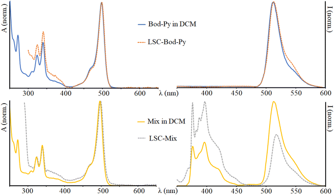 | ||
| Fig. 2 Absorption (on the left) and emission (on the right) spectra of Bod-Py and Mix in DCM and in the LSC. λexc = 350 nm. The spectra of the other species are illustrated in the ESI.† | ||
The absorption spectrum of Py shows a series of bands in the UV region reflecting the vibronic structure of the π → π* transitions (as typical for polycyclic aromatic units) with a maximum at 339 nm. The absorption spectra of Bod-NH2 and Bod-Amide are essentially identical to one another and show a dominant band in the visible region attributable to S0 → S1 (π → π*) transitions, and less intense bands in the UV region due to S0 → S2 transitions. Bod-Py exhibits an absorption spectrum which corresponds to the overlay of Bod-Amide and Py bands, indicating that the electronic coupling between BODIPY and pyrene subunits is negligible at the ground state.
In a fluid solution, Py has a luminescence quantum yield of 13%, with an emission band maximum centred at 395 nm, and an excited state lifetime of 32 ns. The emission spectra of Bod-NH2 and Bod-Amide show a narrow band with a maximum centred at 510 nm and 512 nm, respectively; it is worth noting that the luminescence quantum yield of Bod-NH2 is lower than that of Bod-Amide (Table 1) and this is due to the presence of an amino group in Bod-NH2 which partially quenches the BODIPY excited stated fluorescence via non radiative decay pathways compared to Bod-Amide, where such an effect is downsized. As further confirmation, the excited state lifetime of Bod-NH2 is shorter that that of Bod-Amide. In the emission spectrum of Bod-Py, after excitation in the absorption region of pyrene, the BODIPY fluorescence band is exclusively observable, indicating that Py emission is completely quenched via a quantitative energy transfer mechanism, where excitation energy migrates from *Py to the BODIPY “core” subunit. This is confirmed by the excitation spectrum of Bod-Py which quite well matches the corresponding absorption spectrum (Fig. S4, in ESI†). Moreover, data in Table 1 indicate that covalently connecting a pyrene moiety to BODIPY does not affect φ and τ of Bod-Py compared to those of Bod-Amide (taken as “model” species), as expected in systems where energy transfer processes take place.31 A similar BODIPY–pyrene dyad, connected by one phenyl unit as the spacer, had been investigated by M. Fakis et al. and it was demonstrated that not only the energy transfer process, but also the photoinduced electron transfer process takes place in the dyad when a polar solvent is employed.49–51 To avoid such a process which would quench the luminescence, we decided to use an aliphatic chain as the linker between the chromophoric units in order to decrease the electronic coupling between BODIPY and pyrene compared to a conjugated spacer, thus making the charge separation process less competitive.
By using the Förster equation,17 we calculated the rate constant of the energy transfer mechanism occurring in Bod-Py:
 | (1) |
As a control sample, a physical mixture (meaning a mixture of distinct molecular entities of donor and acceptor units) composed of Bod-Amide and Py in a ratio of 1![[thin space (1/6-em)]](https://www.rsc.org/images/entities/char_2009.gif) :
:![[thin space (1/6-em)]](https://www.rsc.org/images/entities/char_2009.gif) 1 has been prepared in DCM dilute solution (concentration ranging from 1 × 10⁻⁶ M to 8 × 10⁻⁶ M), here named Mix. The absorption spectrum of Mix is identical to that of Bod-Py, while the emission spectrum (excitation in the region where pyrene absorbs) reveals the emission band of the pyrene unit, together with the fluorescence band of the BODIPY unit at lower energy. Additionally, the excited state lifetime of pyrene in Mix is equal to that of Py; furthermore, the excitation spectrum of Mix (λem = 535 nm) perfectly matches the absorption spectrum of Bod-Amide, with no contribution of pyrene bands (Fig. S5 in the ESI†). This demonstrates that in the physical solution Mix, no energy transfer process occurs, probably because it is diffusion-dominated at this low concentration. Indeed, energy transfer efficiency is inversely proportional to the distance between the donor and the emitter,52 meaning that, when they are not covalently bonded, quite a high concentration of chromophores is needed for the energy transfer to occur. As an example, for the case of the diffusion-controlled Förster energy transfer mechanism, the concentration of the emitter should be >1 mM in solution to sufficiently quench the donor emission.53 However, at high concentration values, aggregation phenomena play a key role and can lead to luminescence quenching or enhancement (i.e. AIE, aggregation induced emission). In our case, when a π-conjugated system such as pyrene is involved which undergoes π–π stacking interactions, the high concentration of the luminophore required for the energy transfer process can be responsible for aggregation phenomena that have a counter-effect to quench pyrene's luminescence. To avoid such quenching events, we used diluted solutions (∼10−6 M) for measurements in the liquid phase and in LSCs.
1 has been prepared in DCM dilute solution (concentration ranging from 1 × 10⁻⁶ M to 8 × 10⁻⁶ M), here named Mix. The absorption spectrum of Mix is identical to that of Bod-Py, while the emission spectrum (excitation in the region where pyrene absorbs) reveals the emission band of the pyrene unit, together with the fluorescence band of the BODIPY unit at lower energy. Additionally, the excited state lifetime of pyrene in Mix is equal to that of Py; furthermore, the excitation spectrum of Mix (λem = 535 nm) perfectly matches the absorption spectrum of Bod-Amide, with no contribution of pyrene bands (Fig. S5 in the ESI†). This demonstrates that in the physical solution Mix, no energy transfer process occurs, probably because it is diffusion-dominated at this low concentration. Indeed, energy transfer efficiency is inversely proportional to the distance between the donor and the emitter,52 meaning that, when they are not covalently bonded, quite a high concentration of chromophores is needed for the energy transfer to occur. As an example, for the case of the diffusion-controlled Förster energy transfer mechanism, the concentration of the emitter should be >1 mM in solution to sufficiently quench the donor emission.53 However, at high concentration values, aggregation phenomena play a key role and can lead to luminescence quenching or enhancement (i.e. AIE, aggregation induced emission). In our case, when a π-conjugated system such as pyrene is involved which undergoes π–π stacking interactions, the high concentration of the luminophore required for the energy transfer process can be responsible for aggregation phenomena that have a counter-effect to quench pyrene's luminescence. To avoid such quenching events, we used diluted solutions (∼10−6 M) for measurements in the liquid phase and in LSCs.
LSC preparation and optical characterization
LSCs were fabricated by a thermal activated polymerization, where lauryl methacrylate acted as the monomer, ethyl glycol dimethacrylate as the cross-linking agent, and lauroyl peroxide as the initiator,54 and such a reaction mixture was used to dissolve the synthetized species and Mix. All the LSCs have been prepared using the same concentration of chromophores, to allow for a comparison; adopting 10−6 M as the concentration range of the chromophore in the LSC was a good compromise for having enough chromophores to generate a performant device and at the same time keeping the LSC transparent and only slightly coloured. The LSC fabrication procedure was repeated several times, using different concentrations of BODIPY or pyrene (from 2.2 × 10⁻⁶ M to 8 × 10⁻⁶ M, meaning the chromophore![[thin space (1/6-em)]](https://www.rsc.org/images/entities/char_2009.gif) :
:![[thin space (1/6-em)]](https://www.rsc.org/images/entities/char_2009.gif) initiator ratio was from 1
initiator ratio was from 1![[thin space (1/6-em)]](https://www.rsc.org/images/entities/char_2009.gif) :
:![[thin space (1/6-em)]](https://www.rsc.org/images/entities/char_2009.gif) 8000 to 1
8000 to 1![[thin space (1/6-em)]](https://www.rsc.org/images/entities/char_2009.gif) :
:![[thin space (1/6-em)]](https://www.rsc.org/images/entities/char_2009.gif) 2200 respectively), and detecting always the same photochemical results, on the basis of absorption and emission properties. At temperatures higher than 80 °C, the initiator is activated and starts a radical polymerization reaction which leads to a polyacrylic solid material. Investigations on the optical properties and Monte Carlo ray tracing simulations demonstrated that conventional polyacrylates absorb less light than standard window glasses,55 and this makes them a suitable material for LSC applications.
2200 respectively), and detecting always the same photochemical results, on the basis of absorption and emission properties. At temperatures higher than 80 °C, the initiator is activated and starts a radical polymerization reaction which leads to a polyacrylic solid material. Investigations on the optical properties and Monte Carlo ray tracing simulations demonstrated that conventional polyacrylates absorb less light than standard window glasses,55 and this makes them a suitable material for LSC applications.
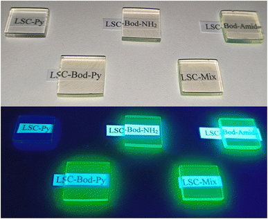
The prepared LSC appears transparent and exhibits BODIPY's (or pyrene's) fluorescence from the borders once irradiated by UV light from the top surface (except for LSC-Py), as shown in Fig. 3.
Comparing the absorption spectra of all the chromophores in the LSC matrix and in DCM solution, no significant difference is noted (just 1 nm red-shift in the LSC matrix compared to the liquid phase).
To calculate the fraction of photons absorbed by the LSC over the solar spectrum from 370 nm to 1050 nm, ηabs-vis, an AM 1.5G solar simulator was used as the irradiation source. The area of AM 1.5G spectra decreased by the presence of the LSCs between the light source and the detector was divided by the area of the solar spectrum. The ηabs-vis values are reported in Table 2 (and graphically observable in Fig. 4 and S6 in the ESI†). For the “blank” LSC (i.e. a LSC without a chromophore inside) the fraction of photons absorbed is 12.13%, and it is related to some incident sunlight confined in the waveguide of the polyacrylic rigid matrix. The value of ηabs-vis for LSC-Py is lower compared to that of the other materials and similar to the value of the blank LSC; this is not surprising considering that the absorption contribution of pyrene in this investigation range (from 370 nm to 1050 nm) is negligible.
| LSC | η abs-vis (%) | x | y | CRI |
|---|---|---|---|---|
| Blank | 12.13 | 0.337 | 0.349 | 96.40 |
| Py | 12.56 | 0.338 | 0.350 | 96.05 |
| Bod-NH2 | 21.62 | 0.344 | 0.348 | 94.45 |
| Bod-Ammide | 21.75 | 0.346 | 0.348 | 93.03 |
| Bod-Py | 25.75 | 0.346 | 0.349 | 93.05 |
| Mix | 25.27 | 0.348 | 0.348 | 91.98 |
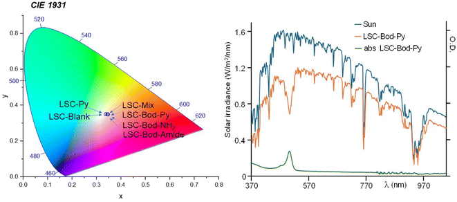 | ||
| Fig. 4 In the left panel: position of the fabricated LSCs in the CIE 1931 chromaticity diagram. In the right panel: in blue, the solar spectrum using an AM 1.5G filter; the orange line represents the transmission spectrum of the solar simulator filtered by LSC-Bod-Py; the absorption spectrum of LSC-Bod-Py is shown in green. LSC-Bod-Py is selected here as a representative example. The spectra of the other prepared LSCs are illustrated in Fig. S6 in the ESI.† | ||
As information on the visual appearance of the semi-transparent slab, we calculated the color rendering index (CRI), reported in Table 2, and the color coordinates using the CIE 1931 chromaticity diagram (see Fig. 4, ESI† for details),56 that are widely investigated parameters to understand the suitability of LSCs in real world BIPV applications. The CRI value of LSC-Py is similar to that of LSC-Blank, since a pyrene unit is only absorbing the UV portion of the solar spectrum; analogously, the CRI of LSC-Bod-Py is almost identical to that of LSC-Bod-Amide. The color coordinates of all the LSCs are located essentially in the central region of the diagram, demonstrating soft coloration of the materials, which is typically a preferable feature for indoor and outdoor illumination. Average visible transmission (AVT) and La*b* coordinates were also calculated and are included in the ESI.†
Once entrapped in the LSC matrix, the emission maximum of BODIPY derivatives is red-shifted and the luminescence lifetime increases (approximately doubles) compared to that of the solution phase (see Table 1 and Fig. 2). The emission spectrum of LSC-Bod-Py does not show pyrene luminescence, thus indicating that the energy transfer mechanism takes place in the solid matrix. The emission spectrum of LSC-Py exhibits the same bands of Py in DCM; however, the luminescence is strongly enhanced in the rigid phase, as demonstrated by the excited state lifetime which is longer in the LSC (202 ns) compared to the liquid solution (32 ns). This behavior is attributed to the rigid matrix effects which decrease the non-radiative rate constants, thus increasing the excited state lifetime and in parallel enhancing the luminescence quantum yield.57–59 Such a trend is further confirmed by measuring Py luminescence at 77 K in the mixture ethanol![[thin space (1/6-em)]](https://www.rsc.org/images/entities/char_2009.gif) :
:![[thin space (1/6-em)]](https://www.rsc.org/images/entities/char_2009.gif) methanol (ratio 4
methanol (ratio 4![[thin space (1/6-em)]](https://www.rsc.org/images/entities/char_2009.gif) :
:![[thin space (1/6-em)]](https://www.rsc.org/images/entities/char_2009.gif) 1) rigid matrix, where the fluorescence lifetime decay is 360 ns.
1) rigid matrix, where the fluorescence lifetime decay is 360 ns.
Comparing the emission spectrum of Mix in DCM and in LSC at equivalent concentration and under excitation at the same wavelength, it is evident that in the liquid phase the BODIPY luminescence is more intense than pyrene emission, while in the LSC matrix the fluorescence band of the pyrene moiety appears more intense than that of the BODIPY unit. This can be explained considering the boosted luminescence quantum yield of Py once in the solid state.
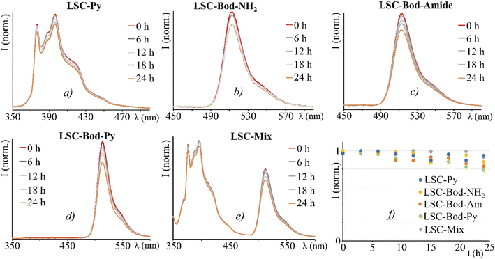
As LSC devices are designed to be exposed to continuous sunlight irradiation, a typical experiment is the photostability test. All the LSCs have been irradiated on the top surface by using an AM 1.5G solar simulator (100 mW cm2) for 24 h, whilst registering the emission spectra.60 Despite a mild decrease for an irradiation time longer than 12 hours, the LSC-chromophores fabricated demonstrate adequate stability (Fig. 5).
Photovoltaic performances
To measure the photocurrent generated by the LSC-PV device, one edge of the LSC had been placed in direct contact with a silicon photovoltaic panel and irradiated perpendicularly at 100 mW cm2 using an AM 1.5G solar simulator,61,62 while the other borders of the LSC were left uncovered. To reduce the contribution of diffused light to the photocurrent, the PV cell was covered with black tape, leaving exposed only the portion necessary for contact with the LSC. Adopting such an experimental set-up, the short-circuit current intensity, I, (mA) was measured and converted into short-circuit current density JLSC (mA cm−2), dividing I by the area of the LSC in contact with the PV cell (J = I/A). Similarly, the short-circuit current density (mA cm−2) of the PV cell, JPV, was obtained by dividing the current intensity by the area of the PV cell directly irradiated by using an AM 1.5G solar simulator (JPV = 15.85 mA cm−2 in our case).63 The so-detected J values, reported in Table 3, were used to calculate the optical efficiency ηopt of the LSC-PV, defined by using eqn (2):64 | (2) |
 | (3) |
| LSC | I (mA) | J LSC (mA cm−2) | G factor | η opt % | η opt abs (%) |
|---|---|---|---|---|---|
| Blank | 0.31 | 0.47 | 1.29 | 2.31 | — |
| (±0.01) | (±0.02) | (±0.01) | (±0.13) | ||
| Py | 0.72 | 1.16 | 1.2 | 6.14 | — |
| (±0.01) | (±0.02) | (±0.01) | (±0.19) | ||
| Bod-NH2 | 0.66 | 1.06 | 1.37 | 4.88 | 51.42 |
| (±0.01) | (±0.02) | (±0.01) | (±0.15) | ||
| Bod-Amide | 0.75 | 1.27 | 1.42 | 5.64 | 58.63 |
| (±0.01) | (±0.02) | (±0.01) | (±0.15) | ||
| Bod-Py | 0.75 | 1.26 | 1.41 | 5.67 | 41.63 |
| (±0.01) | (±0.02) | (±0.01) | (±0.15) | ||
| Mix | 0.8 | 1.52 | 1.37 | 6.98 | 53.12 |
| (±0.01) | (±0.03) | (±0.01) | (±0.18) |
The optical efficiencies, summarized in Table 3, demonstrate adequate performance of LSC-PV devices compared to that of other LSCs based on organic dyes.67 The results highlight that the ηopt of LSC-Bod-NH2 is lower than that of LSC-Bod-Amide, as expected considering that Bod-NH2 is a less emissive species than Bod-Amide, for the reasons discussed above. The optical efficiency of LSC-Bod-Amide is almost the same as that of LSC-Bod-Py, in agreement with the luminescence quantum yield which is not influenced by the presence of pyrene in the molecular structure. LSC-Py exhibits a higher ηopt compared to the LSC based on the synthetized BODIPY derivatives, and this can be explained considering the rigid matrix effect which enhances the luminescence of pyrene compared to that in the solution phase, as is evident looking at the excited state lifetimes (Table 1). LSC-Mix has the best performance among the series, reaching a ηopt value of around 7% that is higher than that of LSC-Bod-Py.
A plausible reason for such results could be attributed to the energy transfer process occurring in LSC-Bod-Py which quenches pyrene's luminescence, and consequently the photons emitted by only the BODIPY unit contribute to the photocurrent generated from the LSC-PV device. Differently, in LSC-Mix, the energy transfer from *Py to the BODIPY unit does not take place, and therefore, pyrene is strongly emissive. As a consequence, the photons emitted by both chromophores in LSC-Mix (i.e. pyrene and BODIPY) contribute to the photocurrent, leading to a better photovoltaic performance compared to that of LSC-Bod-Py where only one chromophore (i.e. BODIPY) emits light.
Some incident light can follow the LSC waveguide thus contributing to the photocurrent of the LSC-PV device. In order to consider such a contribution, the optical efficiency of the LSC-Blank has been calculated and this value (2.31% in our case) can be subtracted from the ηopt of all the prepared LSCs, in order to obtain the real optical efficiency (ηopt real) of the LSC-PV device, that is: 3.83% for LSC-Py, 2.57% for LSC-Bod-NH2, 3.33% for LSC-Bod-Amide, 3.38% for LSC-Bod-Py, and 4.67% for LSC-Mix.
Since the ηopt value strongly depends on the dimension of the LSC and the chromophore luminescence, we calculated the corrected optical efficiency ηopt,abs to also consider the fraction of photons absorbed by the LSC-chromophore, according to eqn (4).
 | (4) |
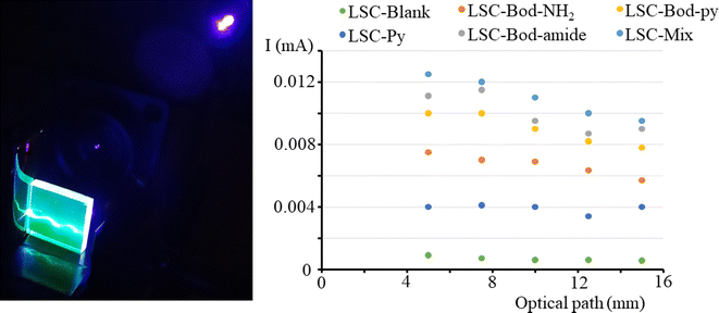
To investigate whether the photocurrent is affected by the position of the irradiation light on the top surface, we measured the I value when the light spot of a laser (at 406 nm) is moved from one edge to another of the LSC side. The results are illustrated in Fig. 6, together with the set-up adopted to perform the experiment. The short circuit current intensity for LSC-Py is low because Py has a low absorption coefficient at the laser irradiation wavelength 406 nm. It is observable that in a LSC based on BODIPY dyes, the photocurrent decreases for a short optical path (meaning the distance between the laser spot on the LSC top surface and LSC border), and then tends towards a plateau. Theoretically, the luminescence intensity reaching the edges should not be influenced by the optical path, which means that the photocurrent should not be altered when the irradiation light is moved from one edge to the other of the slab top surface. In reality, re-absorption events and bulk defects cause the loss of some emitted photons when the optical path is extended, and consequently, the photocurrent slightly decreases.
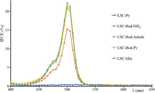
The incident photon conversion efficiency (IPCE) of the LSC-PV device was obtained by measuring the photocurrent as a function of the excitation wavelength. To perform this experiment, the LSC was placed in contact with the PV cell introduced in the sample compartment of a spectrofluorometer. The IPCE has been calculated according to eqn (5):68–71
 | (5) |
Conclusions
A series of chromophores (essentially a pyrene moiety and three BODIPY derivatives) have been synthetized, including a species having a pyrene unit covalently connected to the to the BODIPY “core” (named Bod-Py). Such chromophores were used to fabricate LSCs which appear transparent and slightly coloured and display the fluorophore's bright luminescence from the edges. Photophysical investigations in the liquid and solid state had been performed, and photovoltaic performances are discussed. In our case, the results highlight that the LSC based on the antenna system Bod-Py (where the chromophores are bonded each other) has a lower optical efficiency that the LSC based on the physical mixture (Mix) composed of the BODIPY unit and pyrene (not covalently bonded) at the same concentration.This can be explained considering that in LSC-Bod-Py the donor's (pyrene) luminescence is quenched via an energy transfer process, so only BODIPY's fluorescence is responsible for the photocurrent generated by the device, while in LSC-Mix, both luminophores (BODIPY and pyrene units) contribute to the LSC photocurrent, because non-radiative decay pathways are limited by the donor–acceptor distance and consequently less efficient.
Such results suggest that when a strongly emissive species (like pyrene in our case) is chosen as the energy donor to design an antenna system, the LSC based on the covalently linked donor–acceptor system (where only the acceptor is emissive) would not be more efficient than the LSC based on the physical mixture of the donor and acceptor (where both species emit light). Differently, a good strategy to boost the LSC photovoltaic properties can be to choose a weak-emissive energy donor in order to design an antenna system for a LSC where two (or more) species are covalently bonded, benefitting a wide absorption of the solar spectrum by multiple chromophores and having the excitation energy to be funnelled towards the highly luminescent acceptor.
Conflicts of interest
There are no conflicts of interest to declare.Acknowledgements
This work was funded by the European Union (NextGeneration EU), through the MUR-PNRR project SAMOTHRACE (ECS00000022).References
- N. Armaroli, V. Balzani and N. Serpone, Powering Planet Earth. Energy Solutions for the Future, Wiley-VCH, Weinheim, 2013 Search PubMed.
- T. J. Meyer, M. V. Sheridan and B. D. Sherman, Chem. Soc. Rev., 2017, 46, 6148–6169 RSC.
- D. K. Dogutan and D. G. Nocera, Acc. Chem. Res., 2019, 52, 3143–3148 CrossRef CAS PubMed.
- S. Campagna, F. Nastasi, G. La Ganga, S. Serroni, A. Santoro, A. Arrigo and F. Puntoriero, Phys. Chem. Chem. Phys., 2023, 25, 1504–1512 RSC.
- J. Gong, C. Li and M. R. Wasielewski, Chem. Soc. Rev., 2019, 48, 1862–1864 RSC.
- I. Statistics, Key World Energy Statistics, International Energy Agency, France, 2014 Search PubMed.
- R. Eisenberg and D. G. Nocera, Inorg. Chem., 2005, 44, 6799–6801 CrossRef CAS PubMed.
- E. C. Garnett, B. Ehrler, A. Polman and E. Alarcon-Llado, ACS Photonics, 2021, 8, 61–70 CrossRef CAS PubMed.
- L. Zdražil, et al. , ACS Appl. Energy Mater., 2021, 4, 6445–6453 CrossRef.
- J. Huang, J. Zhou, E. Jungstedt, A. Samanta, J. Linnros, L. A. Berglund and I. Sychugov, ACS Photonics, 2022, 9, 2499–2509 CrossRef CAS.
- J. S. Batchelder, H. Zewai and T. Cole, Appl. Opt., 1979, 18, 3090–3110 CrossRef CAS PubMed.
- B. Petter Jelle, C. Breivik and H. Drolsum Røkenes, Sol. Energy Mater. Sol. Cells, 2012, 100, 69–96 CrossRef CAS.
- B. S. Richards and I. A. Howard, Energy Environ. Sci., 2023, 16, 3214–3239 RSC.
- H. Hernandez-Noyola, D. H. Potterveld, R. J. Holt and S. B. Darling, Energy Environ. Sci., 2012, 5, 5798–5802 RSC.
- J. L. Banal, B. Zhang, D. J. Jones, K. P. Ghiggino and W. W. H. Wong, Acc. Chem. Res., 2017, 50(1), 49–57 CrossRef CAS PubMed.
- M. Kanellis, M. M. de Jong, L. Slooff and M. G. Debije, Renewable Energy, 2017, 103, 647–652 CrossRef CAS.
- M. G. Debije, C. Tzikas, V. A. Rajkumar and M. M. de Jong, Renewable Energy, 2017, 113, 1288–1292 CrossRef.
- M. G. Debije, C. Tzikas, M. M. de Jong, M. Kanellis and L. H. Slooff, Renewable Energy, 2018, 116, 335–343 CrossRef.
- C. Corrado, S. W. Leow, M. Osborn, I. Carbone, K. Hellier, M. Short, G. Alers and S. A. Carter, J. Renewable Sustainable Energy, 2016, 8, 043502 CrossRef.
- M. Vasiliev, K. Alameh and M. Nur-E-Alam, Appl. Sci., 2018, 8, 849 CrossRef.
- A. Arrigo, A. M. Cancelliere, M. Galletta, A. Burtone, G. Lanteri, F. Nastasi and F. Puntoriero, Mater. Adv., 2023, 4, 5200–5205 RSC.
- I. Papakonstantinou, M. Portnoi and M. G. Debije, Adv. Energy Mater., 2021, 11, 2002883 CrossRef CAS.
- A. Albrecht, D. Pfennig, J. Nowak, M. Grunwald and P. J. Walla, Nano Sel., 2020, 1, 525–538 CrossRef.
- M. M. Willich, L. Wegener, J. Vornweg, M. Hohgardt, J. Nowak, M. Wolter, C. R. Jacob and P. J. Walla, Proc. Natl. Acad. Sci. U. S. A., 2020, 117, 32929–32938 CrossRef CAS PubMed.
- A. Pieper, M. Hohgardt, M. Willich, D. A. Gacek, N. Hafi, D. Pfennig, A. Albrecht and P. J. Walla, Nat. Commun., 2018, 9, 666 CrossRef PubMed.
- R. Mazzaro and A. Vomiero, Adv. Energy Mater., 2018, 8, 1801903 CrossRef.
- K. Wu, H. Li and V. I. Klimov, Nat. Photon., 2018, 12, 105–110 CrossRef CAS.
- K. Kim, S. K. Nam, J. Cho and J. H. Moon, Nanoscale, 2020, 12, 12426–12431 RSC.
- S. Castelletto and A. Boretti, Nano Energy, 2023, 109, 108269 CrossRef CAS.
- V. Balzani, P. Ceroni and A. Juris, Photochemistry and Photophysics: Concepts, Research, Perspectives, Wiley-VCH, Weinheim, 2014 Search PubMed.
- B. A. Swartz, T. Cole and A. H. Zewail, Opt. Lett., 1977, 1, 73–75 CrossRef CAS PubMed.
- C. Tummeltshammer, M. Portnoi, S. A. Mitchell, A.-T. Lee, A. J. Kenyon, A. B. Tabor and I. Papakonstantinou, Nano Energy, 2017, 32, 263–270 CrossRef CAS.
- N. J. L. K. Davis, R. W. MacQueen, D. A. Roberts, A. Danos, S. Dehn, S. Perrier and T. W. Schmidt, J. Mater. Chem. C, 2016, 4, 8270–8275 RSC.
- J. t. Schiphorst, A. M. Kendhale, M. G. Debije, C. Menelaou, L. M. Herz and A. P. H. J. Schenning, Chem. Mater., 2014, 26, 3876–3878 CrossRef.
- G. D. Gutierrez, I. Coropceanu, M. G. Bawendi and T. M. Swager, Adv. Mater., 2016, 28, 497–501 CrossRef CAS PubMed.
- B. Zhang, G. Lyu, E. A. Kelly and R. C. Evans, Adv. Sci., 2022, 9, 2201160 CrossRef PubMed.
- C. Tummeltshammer, A. Taylor, A. J. Kenyon and I. Papakonstantinou, J. Appl. Phys., 2014, 116, 173103 CrossRef.
- B. Balaban, S. Doshay, M. Osborn, Y. Rodriguez and S. A. Carter, J. Lumin., 2014, 146, 256–262 CrossRef CAS.
- J. Graffion, X. Catto, M. Wong Chi Man, V. R. Fernandes, P. S. Andre, R. A. S. Ferreira and L. D. Carlos, Chem. Mater., 2011, 23, 4773–4782 CrossRef CAS.
- B. Matarranz and G. Fernández, Chem. Phys. Rev., 2021, 2, 041304 CrossRef CAS.
- F. Nastasi, P. G. Mineo, J. Barichello, G. La Ganga, G. Di Marco, G. Calogero and M. Cordaro, Biomimetics, 2022, 7, 110 CrossRef CAS PubMed.
- R. Ziessel, G. Ulrich and A. Harriman, New J. Chem., 2007, 31, 496–501 RSC.
- M. Trapani, M. A. Castriciano, E. Collini, G. Bella and M. Cordaro, Org. Biomol. Chem., 2021, 19, 8118–8127 RSC.
- M. Trapani, M. A. Castriciano, J. A. A. W. Elemans, P. Mineo, A. Nicosia and M. Cordaro, Synlett, 2021, 32, 1714–1718 CrossRef CAS.
- M. Cordaro, P. Mineo, F. Nastasi and G. Magazzù, RSC Adv., 2014, 4(83), 43931–43933 RSC.
- O. A. Bozdemir, S. Erbas-Cakmak, O. O. Eki, A. Dana and E. U. Akkaya, Angew. Chem., 2011, 123, 11099–11104 CrossRef.
- N. J. L. K. Davis, R. W. MacQueen, D. A. Roberts, A. Danos, S. Dehn, S. Perrier and T. W. Schmidt, J. Mater. Chem. C, 2016, 4, 8270–8275 RSC.
- A. Vazquez-Romero, N. Kielland, M. J. Arevalo, S. Preciado, R. J. Mellanby, J. Richard, Y. Feng, R. Lavilla and M. Vendrell, J. Am. Chem. Soc., 2013, 135, 16018–16021 CrossRef CAS PubMed.
- M. Fakis, J. S. Beckwith, K. Seintis, E. Martinou, C. Nançoz, N. Karakostas, I. Petsalakis, G. Pistolis and E. Vauthey, Phys. Chem. Chem. Phys., 2018, 20, 837–849 RSC.
- P. Porcu, I. González-Méndez, K. Sorroza-Martínez, A. S. Estrada-Montaño, F. Cuétara-Guadarrama, M. Vonlanthen and E. Rivera, Dyes Pigm., 2022, 207, 110713 CrossRef CAS.
- S. T. Bailey, G. E. Lokey, M. S. Hanes, J. D. M. Shearer, J. B. McLafferty, G. T. Beaumont, T. T. Baseler, J. M. Layhue, D. R. Broussard, Y.-Z. Zhang and B. P. Wittmershaus, Sol. Energy Mater. Sol. Cells, 2007, 91, 67–75 CrossRef CAS.
- V. Balzani and F. Scandola, Supramolecular Photochemistry, Horwood, Chichester, 1991 Search PubMed.
- B. Zhang, C. Gao, H. Soleimaninejad, J. M. White, T. A. Smith, D. J. Jones, K. P. Ghiggino and W. W. H. Wong, Chem. Mater., 2019, 31, 3001–3008 CrossRef CAS.
- (a) R. Mazzaro, A. Gradone, S. Angeloni, G. Morselli, P. G. Cozzi, F. Romano, A. Vomiero and P. Ceroni, ACS Photonics, 2019, 6, 2303–2311 CrossRef CAS; (b) J. Bomm, A. Büchtemann, A. Fiore, L. Manna, J. H. Nelson, D. Hill and W. G. J. H. M. van Sark, Beilstein J. Nanotechnol., 2010, 1, 94–100 CrossRef CAS PubMed; (c) I. Coropceanu and M. G. Bawendi, Nano Lett., 2014, 14, 4097–4101 CrossRef CAS PubMed.
- F. Meinardi, F. Bruni and S. Brovelli, Nat. Rev. Mater., 2017, 2, 17072 CrossRef CAS.
- Average visible transmission (AVT), color rendering index (CRI) and color coordinates (LAB) have been calculated by using the calculator provided in the ESI† of the article: C. Yang, D. Liu, M. Bates, M. C. Barr and R. R. Lunt, How to Accurately Test, Characterize, and Report Transparent Solar Cells, Joule, 2019, 3, 1803–1809 CrossRef.
- R. Dabestani and I. N. Ivanov, Photochem. Photobiol., 1999, 70, 10–34 CAS.
- N. J. Turro, Modern Molecular Photochemistry, Benjamin Cummings, Manlo Park, CA, 1978 Search PubMed.
- A. Arrigo, F. Nastasi, G. La Ganga, F. Puntoriero, G. Zappalà, A. Licciardello, M. Cavazzini, S. Quici and S. Campagna, Chem. Phys. Lett., 2017, 683, 96–104 CrossRef CAS.
- Y. Zhou, D. Benetti, X. Tong, L. Jin, Z. M. Wang, D. Ma, H. Zhao and F. Rosei, Nano Energy, 2018, 44, 378–387 CrossRef CAS.
- F. Purcell-Milton and Y. K. Gun'ko, J. Mater. Chem., 2012, 22, 16687 RSC.
- (a) C. Yang, et al. , Joule, 2022, 6(1), 8–15 CrossRef; (b) M. G. Debije, R. C. Evans and G. Griffini, Energy Environ. Sci., 2021, 14, 293–301 RSC.
- H. Zhao, D. Benetti, L. Jin, Y. Zhou, F. Rosei and A. Vomiero, Small, 2016, 12, 5368 CrossRef CAS.
- Y. Zhou, D. Benetti, Z. Fan, H. Zhao, D. Ma, A. O. Govorov, A. Vomiero and F. Rosei, Adv. Energy Mater., 2016, 6, 1501913 CrossRef.
- M. Aghaei, R. Pelosi, W. W. H. Wong, T. Schmidt, M. G. Debije and A. H. M. E. Reinders, Prog. Photovoltaics, 2022, 30, 726–739 CAS.
- G. Griffini, M. Levi and S. Turri, Renewable Energy, 2015, 78, 288–294 CrossRef CAS.
- J. Roncali, Adv. Energy Mater., 2020, 10, 2001907 CrossRef CAS.
- Y. Wang, X. Shi, T. Oshikiri, S. Zu, K. Ueno and H. Misawa, Nanoscale, 2020, 12, 22674–22679 RSC.
- Z. Chen, et al. , J. Mater. Res., 2010, 25, 3 CrossRef CAS.
- R. E. Adam, M. Pirhashemib, S. Elhag, X. Liuc, A. Habibi-Yangjehb, M. Willandera and O. Nur, RSC Adv., 2019, 9, 8271–8279 RSC.
- D. Ogermann, T. Wilke and K. Kleinermanns, Open J. Phys. Chem., 2012, 2, 47–57 CrossRef CAS.
- J. L. Banal, K. P. Ghiggino and W. W. H. Wong, Phys. Chem. Chem. Phys., 2014, 16, 25358 RSC.
Footnote |
| † Electronic supplementary information (ESI) available: Materials and methods adopted; synthetic procedures and characterization; spectroscopic data; LSC preparations; data on photovoltaic investigations. See DOI: https://doi.org/10.1039/d4se00329b |
| This journal is © The Royal Society of Chemistry 2024 |

