
 Open Access Article
 This Open Access Article is licensed under a
 Creative Commons Attribution 3.0 Unported Licence
Differences in interaction of graphene/graphene oxide with bacterial and mammalian cell membranes†
Victor
Lanai‡
ac,
Yanyan
Chen‡
a,
Elena
Naumovska
b,
Santosh
Pandit
 a,
Elsebeth
Schröder
c,
Ivan
Mijakovic
*ad and
Shadi
Rahimi
*a
a,
Elsebeth
Schröder
c,
Ivan
Mijakovic
*ad and
Shadi
Rahimi
*a
aDivision of Systems and Synthetic Biology, Department of Life Sciences, Chalmers University of Technology, SE-41296 Gothenburg, Sweden. E-mail: shadir@chalmers.se; ivan.mijakovic@chalmers.se
bEnergy and Materials division, Department of Chemistry and Chemical Engineering, Chalmers University of Technology, SE-41296 Gothenburg, Sweden
cQuantum Device Physics Laboratory, Department of Microtechnology and Nanoscience-MC2, Chalmers University of Technology, SE-41296 Gothenburg, Sweden
dThe Novo Nordisk Foundation Center for Biosustainability, Technical University of Denmark, DK-2800 Kgs. Lyngby, Denmark
First published on 15th December 2023
Abstract
Graphene, a single layer, hexagonally packed two-dimensional carbon sheet is an attractive candidate for diverse applications including antibacterial potential and drug delivery. One of the knowledge gaps in biomedical application of graphene is the interaction of these materials with the cells. To address this, we investigated the interaction between graphene materials (graphene and graphene oxide) and plasma membranes of cells (bacterial and mammalian cells). The interactions of four of the most abundant phospholipids in bacteria and mammalian plasma membranes with graphene materials were studied using density functional theory (DFT) at the atomic level. The calculations showed that the mammalian phospholipids have stronger bonding to each other compared to bacterial phospholipids. When the graphene/graphene oxide sheet is approaching the phospholipid pairs, the bacterial pairs exhibit less repulsive interactions, thereby a more stable system with the sheets was found. We also assembled bacterial and mammalian phospholipids into liposomes. We further observed that the bacterial liposomes and cells let the graphene flakes penetrate the membrane. The differential scanning calorimetry measurements of liposomes revealed that the bacterial liposomes have the lowest heat capacity; this strengthens the theoretical predictions of weaker interaction between the bacterial phospholipids compared to the mammalian phospholipids. We further demonstrated that graphene oxide could be internalized into the mammalian liposomes without disrupting the membrane integrity. The results suggest that the weak bonding among bacteria phospholipids and less repulsive force when graphene materials approach, result in graphene materials interacting differently with the bacteria compared to mammalian cells.
Introduction
Graphene (G), an allotrope of carbon, consists of a single layer of atoms arranged in a hexagonal lattice nanostructure. It has been shown that vertically grown G flakes are effective in killing bacteria,1 whilst maintaining mammalian (eukaryotic) cells intact.2 It was also reported that graphene oxide (GO) sheets, the oxidized form of G, can attach to certain drugs and thereby be utilized as a therapeutic drug carrier for cancer treatment.3,4 Understanding the detailed interaction of these materials with living cells is of great significance and would help to choose the appropriate graphene material for the right biomedical application.We recently reviewed the proposed interaction mechanisms between graphene materials and bacteria including mechanical damage, electron transfer, insertion, lipid extraction, pore formation, and wrapping.5 Molecular dynamics simulations showed the adsorption and insertion as the interaction modes of graphene and membrane lipids. Graphene can be transiently adsorbed onto the membrane. In the adsorption interaction mode, the lipids locally splay and twist thereby providing a hydrophobic environment for the graphene contact. However, the most favourable interaction mode is the insertion mode: graphene can also be inserted in the membrane hydrophobic region preferably in the perpendicular orientation to the membrane surface.6
Feng et al., (2021) investigated the interactions of GO with the eukaryotic cell membrane model containing zwitterionic and anionic lipids, and cholesterol using quartz crystal microbalance with dissipation monitoring (QCM-D) system. The efficiency of GO attachment to the membrane was reduced by increasing the content of anionic lipids in the membrane, indicating the essential role of electrostatic interactions in deposition of GO.7
Although molecular dynamics simulations were previously used to study the interactions between graphene materials and cell membranes,8–11 none of these studies investigated the differences in the interaction of these materials with the bacteria and mammalian membranes.
Given that the plasma membrane is the first part of a cell interacting with graphene materials, it is important to investigate the interaction of the plasma membrane with the graphene materials. The key component of the plasma membrane is phospholipids, which represents the most extensive and structurally significant component in the lipid bilayer composition.
In this study, we first investigate the interaction of graphene materials with phosphatidylglycerol (PG) and cardiolipin (CL), phosphatidylcholine (PC) and sphingomyelin (SM), the dominant phospholipids in the outer leaflet of the bacteria and mammalian membranes, respectively. The purpose is to investigate if the different constituents in head-group of phospholipids affect the interactions with graphene materials. Density functional theory (DFT) was utilized to study the interaction of phospholipids with graphene materials at a quantum level. Phospholipids were simulated as the single molecules as well as in pairs, in combinations that are relevant for the membranes. When the G sheets were approaching the phospholipid pairs perpendicular to the membrane surface, the bacterial lipids exhibited less repulsion towards G than their mammalian counterparts. This is expected to facilitate the penetration of graphene materials in the bacterial membrane, verified experimentally on Staphylococcus aureus and bacterial liposomes. We hypothesized that stronger repulsion by mammalian lipids prevents destructive interaction with the mammalian membrane, and favors non-destructive interactions. To verify this, we assembled mammalian phospholipids into liposomes, mimicking a cell membrane. GO interacts with the mammalian liposomes without disrupting the membrane integrity.
Results and discussion
Bacterial phospholipids display weak bonding compared to mammalian phospholipids
PG and CL,12 and PC and SM as the major constituents in bacteria and mammalian membranes were selected, respectively13,14 (ESI Fig. 2†). The phospholipids were paired and their atomic positions further relaxed (Fig. 1A). PG/PG, CL/CL, CL/PG pairs, and PC/PC, PC/SM, SM/SM pairs were simulated as part of the bacterial and mammalian membranes, respectively.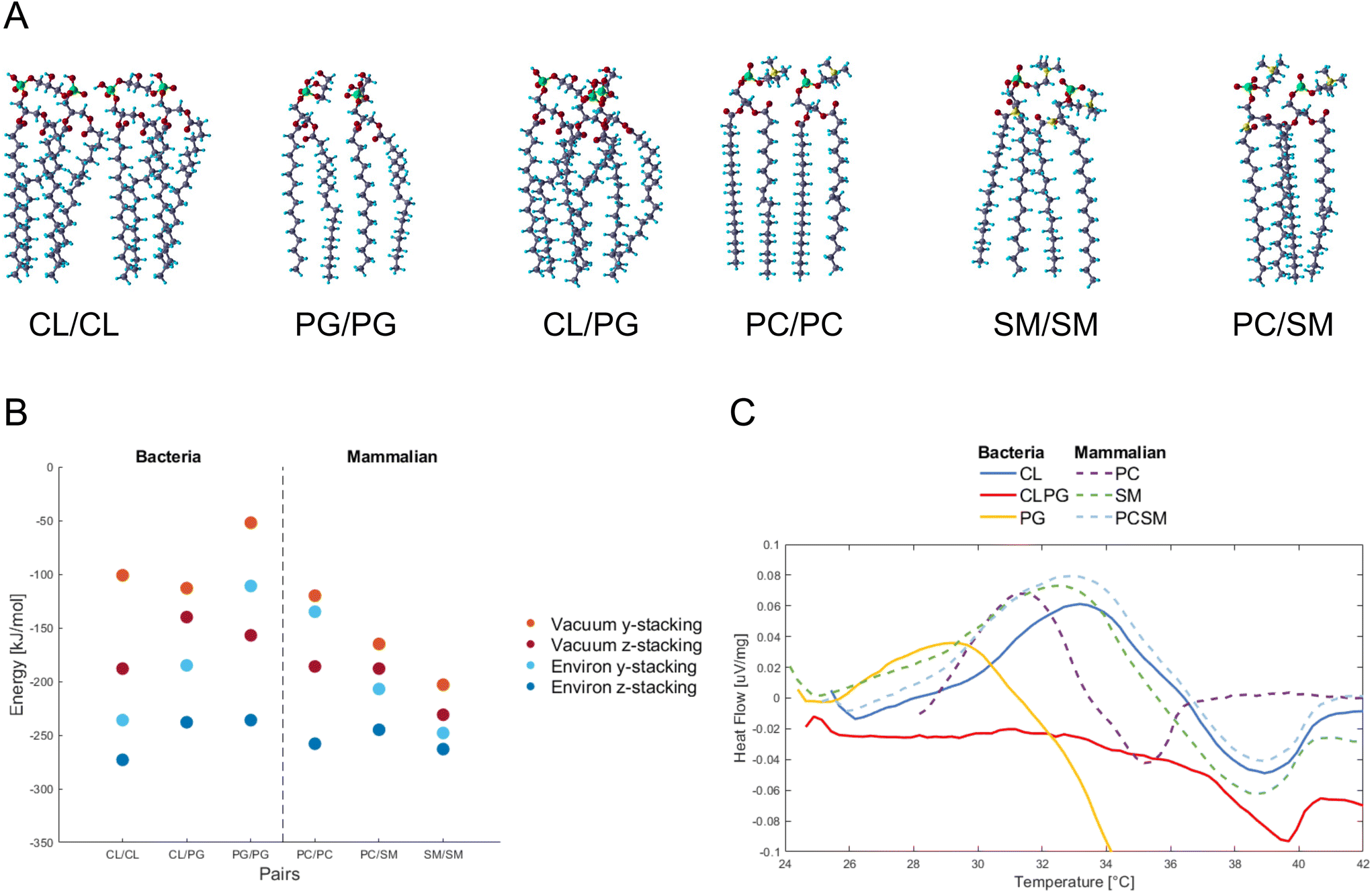 | ||
| Fig. 1 (A) Molecular structure of paired phospholipids used in this study. Shown are the so-called “y-stacked” relative orientation of the molecules, the “z-stacked” orientation is obtained by a 90° rotation of each phospholipid around its long axis. The atom colors are O: red, C: dark blue, H: light blue, P: green, N: yellow. (B) Interaction energy between paired phospholipids. Orange and red represent calculations in vacuum, while light and dark blue shows the calculations with the water environment. (C) The differential scanning calorimetric analysis curves from synthesized bacteria and mammalian liposomes in the range of 25–42 °C. Abbreviations are CL, cardiolipin; PC, phosphatidylcholine; PG, phosphatidylglycerol; SM, sphingomyelin. | ||
Fig. 1B shows the energy change by pairing the phospholipids in vacuum or in water, and for two relative orientations of each phospholipid pair, termed y- and z-stacking, relative to the energy of the two phospholipids isolated. Negative values indicate binding. We find that as the number of legs interacting between the phospholipids increases, the absolute value of the energy increases. An interesting finding is how the hydroxides (OH) in the PG/PG molecules arrange into H-bonds within each molecule (ESI Fig. 3†), instead of between the molecules, as in the other phospholipid pairs. This could explain why the distance between two PG molecules is more open and less robust than in the other combinations studied here.
Interaction energies between phospholipids of mammalian cells are more negative (bind stronger) than in bacterial phospholipids. The presence of SM seems to lower the energy, and SM/SM shows the strongest interaction in the mammalian pairs. For the PC/SM pair, an overlap in the hydrocarbon tails takes place, allowing for a denser stacking. The heads of PC/PC and PC/SM have more H-atoms and higher competition to available O-atoms of the same molecule, and thus tilt towards their neighbors for higher availability of interactions.
Overall, the calculations suggest that the intermolecular attraction between the bacterial PG phospholipid pair is weaker than that of other phospholipid pairs in most of the tested conditions (vacuum y-stacking, environ y/z stacking).
To verify experimentally the results found by DFT calculations, we assembled CL and PG, PC and SM phospholipids into liposomes representing bacteria and mammalian membranes, respectively. The differential scanning calorimetric analysis (DSC) was performed for the liposomes to reveal if the constituents of phospholipids affect the heat capacity of the liposomes (Fig. 1C).
In case of bacterial liposomes, the endothermic peak takes place at a lower temperature (29.2 °C, 0.036 μV mg−1) for PG compared to the other liposomes, which indicates that the amount of heat needed for the endothermic reaction is lower.
By calculating the integral for each endothermic peak, with respect to time (not temperature), we obtained the heat capacity as μV s mg−1 (Table 1). The bacterial liposomes display the lowest heat capacity, while the mammalian liposomes have the highest heat capacity. Next, the values from the calculated heat capacities were converted from μV s mg−1 to μV s mol−1 and plotted against the theoretical calculations and they follow the same pattern and range (ESI Fig. 4†). This supports the theoretical predictions of weaker interaction between the bacterial phospholipids compared to the mammalian phospholipids.
| Organisms | Phospholipid | Heat capacity [μV s mg−1] |
|---|---|---|
| Bacteria liposome | CL/CL | 0.176 |
| PG/PG | 0.093 | |
| CL/PG | — | |
| Mammalian liposome | PC | 0.229 |
| SM | 0.301 | |
| PC/SM | 0.279 |
It was previously demonstrated that GO and chemically reduced GO disrupt 1,2-dioleoyl-sn-glycero-3-phosphocholine (DOPC) vesicles through a lipid-extraction mechanism.15 Molecular dynamics simulations showed that GO can be embedded in the membrane, and pull out membrane lipids to the surface of GO, resulting in pore formation and water molecules flowing into the membrane.16 It was previously discussed that under moderate attraction between the lipid headgroup and GO, the appropriate degree of rotational freedom for GO is favorable to the hydrogen-bonding interaction between GO and the C![[double bond, length as m-dash]](https://www.rsc.org/images/entities/char_e001.gif) O group in the phosphatide hydrophobic region, thereby triggering the insertion of GO into the lipid alkyl chain region and leading to the extraction of lipids.17 Based on our results, we propose that the weak intermolecular interaction among bacterial lipids may help in the extraction of lipids by G/GO.
O group in the phosphatide hydrophobic region, thereby triggering the insertion of GO into the lipid alkyl chain region and leading to the extraction of lipids.17 Based on our results, we propose that the weak intermolecular interaction among bacterial lipids may help in the extraction of lipids by G/GO.
Weak repulsion allows graphene materials to approach bacterial membrane
G/GO flakes approaching the heads of bacteria phospholipid pairs were studied by calculating the interaction energy between the G/GO and phospholipid pairs at different distances (Fig. 2A). Negative energy values represent attractive forces between the phospholipids and G/GO. When G/GO approaches the lipid pair beyond the energetically optimal distance (the phospholipids still together in their optimal binding separation), energies increase and eventually positive values may be found, indicating repulsion. For the bacterial systems, the most stable (lowest energies) distance is around 1 Å. Beyond this point, there is no significant repulsion when G approaches the membrane further. This is in line with previous reports, showing that graphene materials, when approaching bacteria at a 90° angle, are particularly deadly for bacteria.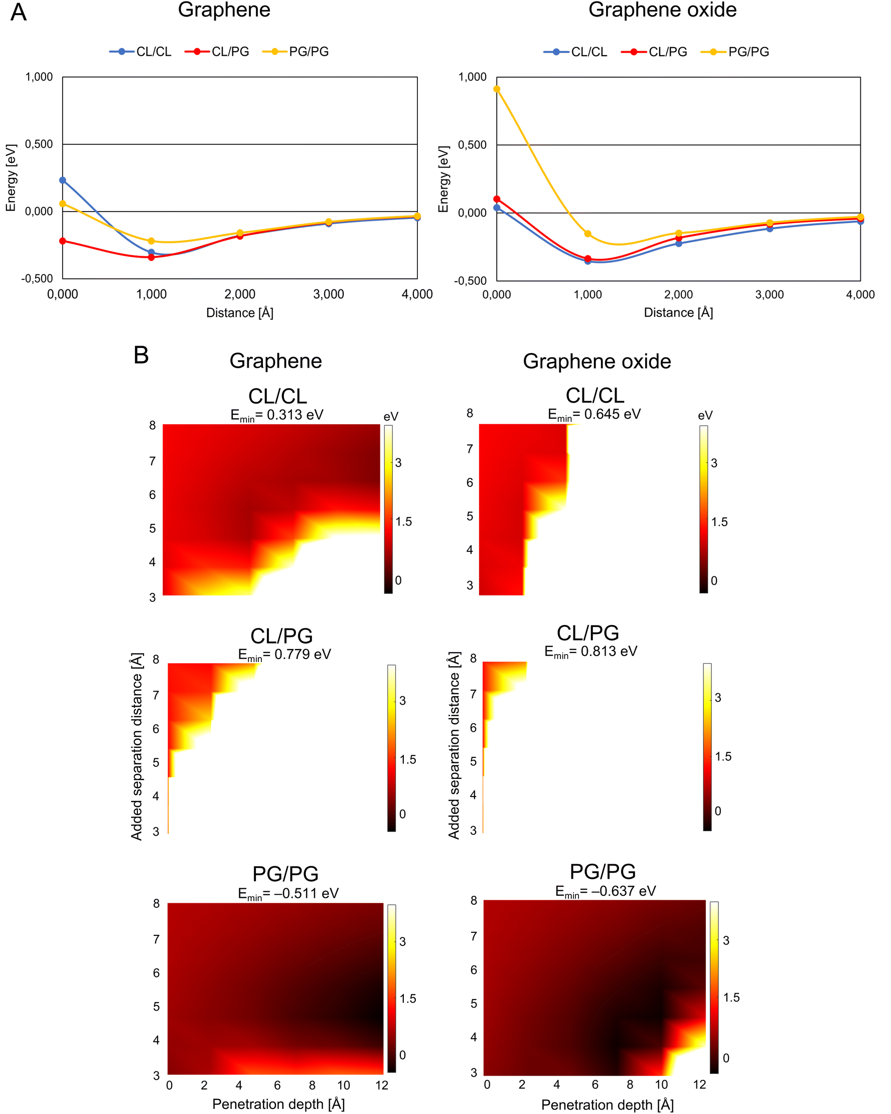 | ||
| Fig. 2 Graphene/graphene oxide interaction with the bacteria membrane. (A) Interaction energy when graphene/graphene oxide approaches paired bacteria phospholipids. The distance is defined as the x-component of the shortest path between any atom on the phospholipid pair and on G/GO. (B) Energy landscape of the interaction energy when graphene/graphene oxide is inserted between paired phospholipids, color scale as indicated by the right-hand bars in eV units. The white and black colors represent the strongest repulsion of and strongest attraction to insertion of graphene/graphene oxide between the phospholipids, with the lowest energy indicated by Emin in the headers. Abbreviations as in Fig. 1. | ||
To further test this hypothesis, we produced a surface coated with vertically aligned G flakes. We used a simple experimental setup different from previous studies, coating a polymers surface with the graphene in sonication water bath. The polymer surface coated with G was incubated in the presence of S. aureus at 37 °C for 24 h and further imaged by SEM (ESI Fig. 5A†). Compared to control, where abundant bacterial growth was obvious, on G-coated surfaces there were few surviving bacteria, we found evidence of the bacteria cells interacting closely with the graphene flakes. Interestingly, the G-coated polymer did not affect the viability of breast epithelial cells when compared to the cells grown on medium only (ESI Fig. 5B†).
Based on our DFT calculations, we find that the G sheets are more suitable for antibacterial application than GO sheets, a result that is in line with our previous study that indicates that Bacillus subtilis and Pseudomonas aeruginosa bacteria can grow on GO integrated solid agar-based nutrient plates.18 However, this study investigated the growth of bacteria on GO-supplemented medium and did not assess the interaction of GO with the bacterial membrane.
A theoretically calculated analysis of G and GO penetrating paired phospholipids was performed with the phospholipids at different separation distances (Fig. 2B and 3B). This gave us an energy landscape for each of the phospholipid pairs, with the penetration depth of the G/GO and the separation distance between the phospholipids as the two variables.
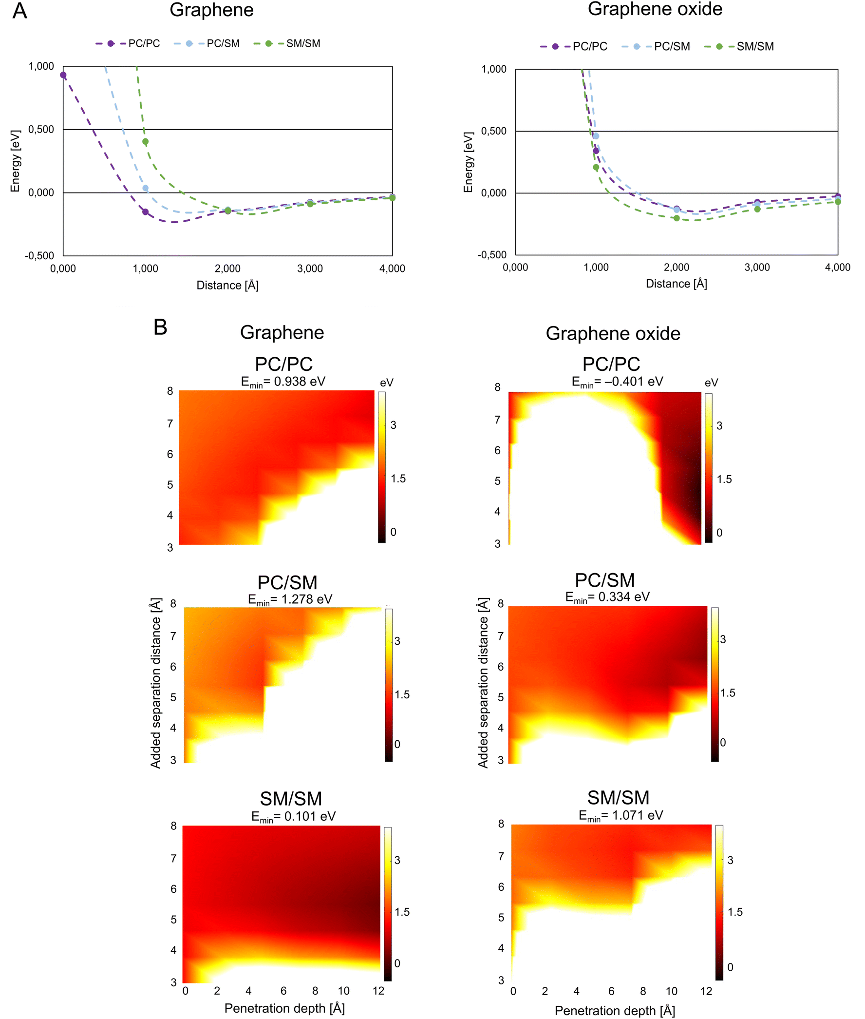 | ||
| Fig. 3 Graphene/graphene oxide interaction with mammalian membrane. (A) Interaction energy when graphene/graphene oxide approaches paired mammalian phospholipids. (B) Interaction energy when graphene/graphene oxide is inserted between paired mammalian phospholipids. Color coding as in Fig. 2B, abbreviations as in Fig. 1. | ||
The PG/PG pair shows the most dramatic response to the G/GO flakes compared to other phospholipid pairs. We find that once the G/GO has started entering between the PG/PG pair and the pair has been separated a few Å from their original binding distance, the PG/PG pair still repels G/GO in some distance combinations (white and orange regions of the plots) but now also exhibits attraction at other distance combinations (dark regions). The repulsion regions are more pronounced in other pairs than PG/PG, while attraction only exists for the PG/PG pair. This indicates that the phospholipid pair PG/PG needs less separation to be stable when G/GO is penetrating. The PG/PG pair even shows a small attraction to G/GO (Emin = −0.511 eV for G and Emin = −0.637 eV for GO). Based on a previous simulation study,19 the penetration probability of graphene into the PG bilayer is 80%, which is consistent with our theoretical calculations.
We also find some differences in the interaction of bacterial phospholipids with GO compared with that of G. As indicated (Fig. 2A and B), there is a repulsion while GO is approaching PG/PG and the repulsion is more pronounced when GO penetrates the CL/CL pair. These results are similar to previous results in a study by Romero-Vargas Castrillón et al. (2015). They investigated the interaction of GO and the Escherichia coli cell membrane using atomic force microscopy (AFM). The interaction was predominantly repulsive, and it was a result of the repulsion between the outer cell membrane and hydrophilic GO.20
While PG is the major component of bacterial membranes, it is not widely found in animal cells, which makes it a potential candidate for bacterial targeting. A small synthetic receptor that specifically targets anionic PG head groups recently showed a broad antibacterial activity.21 In our study, the weaker mutual bonding and lower heat capacity of PG pairs, as well as attraction of graphene materials proposes the PG as the potential candidate for graphene-based targeted antibacterial drug delivery to the pathogenetic bacteria that have PG in their membrane.
Strong repulsion from mammalian phospholipid pairs leads to non-destructive interactions with graphene materials
G/GO flakes approaching the heads of mammalian phospholipid pairs were studied by calculations that were similar to those for the bacterial phospholipid pairs (Fig. 3A). Unlike bacterial phospholipids, the mammalian systems show large repulsion forces at 1 Å distance from G/GO in almost all cases. The major difference between G and GO in the interaction with mammalian phospholipid pairs is that the repulsive response takes place at a longer distance when GO approaches. GO has oxygen-based functional groups attached to the surface, which might interact with the heads of the phospholipids electrostatically, at longer distances than pure G. A strong repulsion from PC, PC/SM, and SM pairs prevents GO from approaching. However, in case of the G sheet, it seems that the pairs, especially PC, can be reached by the G sheet. Based on this result, GO cannot approach the mammalian membrane at a 90° angle. Hence, it is more likely that it interacts with the mammalian membrane in a less destructive way. It is suggested that the GO is more suitable than G for use as a drug nano-carrier to human cells, as we expect that the drug carrier should not reach the membrane and affect the membrane integrity through physical damage.Fig. 3B presents the results of the G/GO penetration and mammalian phospholipids separation. All the mammalian pairs have more white regions at a lower penetration depth, and thus, are more repulsive to G/GO when G/GO intercalates. When comparing G with GO, in case of mammalian phospholipids the smaller repulsion of G/GO (dark orange region) is more pronounced in SM/SM when G is penetrating, although attraction is not found (Emin has a small, positive value). This is different from penetration by GO in SM/SM, where stronger repulsion of GO (white region) is more pronounced. These results are consistent with previous simulation study showed that GO sheets with hydrophilic corners (owing to carboxylic, hydroxyl, and epoxide functional groups of GO) do not undergo cell uptake.22 This is further evidence for suitability of GO as a nano-carrier for drug delivery to human cells. GO does not disrupt the mammalian membrane and thereby the membrane integrity can be maintained during uptake of GO, carrying drugs.
Destructive interaction of GO with bacterial liposomes versus non-destructive interactions of GO with mammalian liposomes
To test the assumptions based on the theoretical calculations, a calcein release experiment was performed to determine the interaction between GO with bacterial (PG and CL)/mammalian (PC, SM, and PE) liposomes (Fig. 4A). Calcein is a well-known fluorescence probe which is self-quenched at high concentration (>80 mM), but it emits a strong fluoresce when diluted. We prepared calcein loaded bacteria/mammalian liposomes. Then the liposomes were exposed to 5 mg mL−1 GO for 6 h at room temperature. We did not observe any significant difference in the fluorescence intensity of GO treated mammalian liposomes compared to the control (Fig. 4B). Thus, there was no release of calcein from the liposome, indicating that GO did not disrupt the mammalian liposome. Meanwhile, 20% leakage of calcein was identified for bacteria liposome under the same experimental condition. The increase of membrane permeability in bacterial liposomes compared to the mammalian liposomes is a solid proof that GO could bind with the bacterial phospholipids, compromise the integrity of bacterial membrane, and eventually lead to some percentage of leaking out the components inside the liposomes. The result is in line with our simulation that mammalian phospholipids preferred strongly bonding with each other and repulsing of approaching GO, whereas bacterial membrane phospholipids showed weak bonding to each other thereby allowing GO to penetrate.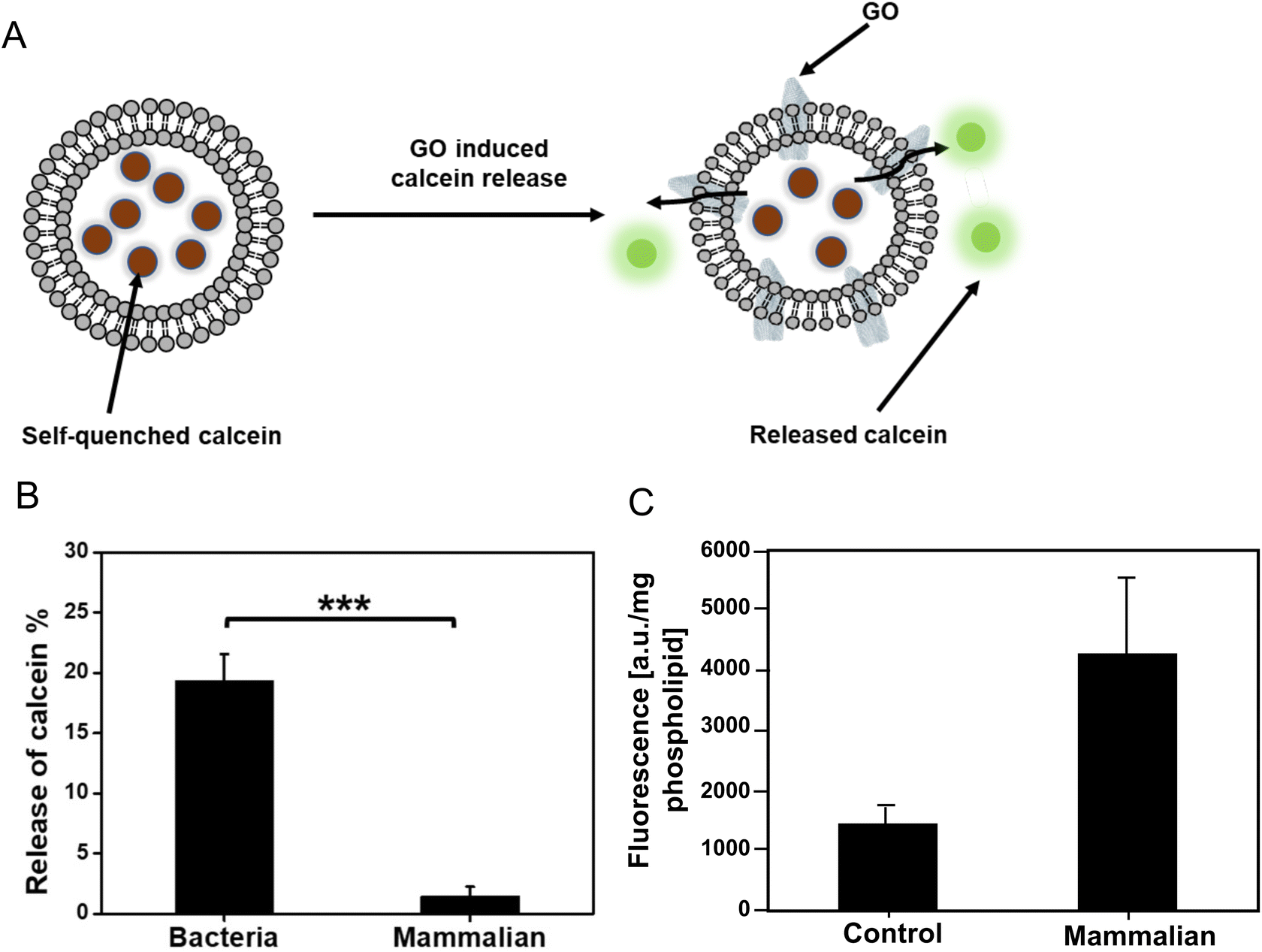 | ||
| Fig. 4 Graphene oxide (GO) interaction with bacteria/mammalian liposomes. (A) A schematic illustration of GO induced calcein release from bacteria liposome. (B) The percentage of released calcein from bacteria liposomes and mammalian liposomes after exposure to GO for 6 h at room temperature. The concentration of GO was 5 mg mL−1. The fluorescence intensity of all samples was recorded using a microplate reader, where the excitation and emission wavelength was 485 nm and 520 nm, respectively. p-Values are calculated using a Student's two-tailed t-test. Symbol is defined as follows: ***p ≤ 0.001. (C) GO-fluorescein internalization into mammalian liposome (expressed as per liposome or phospholipid content). The control is the liposomes without any treatment. | ||
To verify the non-destructive interactions of GO with mammalian liposomes, we also covalently functionalized GO with fluorescein (F) to track the GO localization. The successful functionalization of GO was confirmed by increment in size and fluorescence intensity of GO-F after functionalization (ESI Fig. 6†). The mammalian liposomes were exposed to the GO-F for 6 h and they were subsequently collected by solvent-based precipitation and analyzed (Fig. 4C). The fluorescent signal from the mammalian liposomes was significantly higher than the control liposomes without any treatment, which indicates the interaction of GO-F with the liposomes while keeping the liposomes still intact. Fluorescent microscopic observation of GO-F treated mammalian liposomes showed the intact liposomes with fluorescent signal (ESI Fig. 7†). The result is in line with our theoretical simulation and calcein release experiment that GO interacts with the mammalian membrane without disrupting the integrity. Our group previously investigated the interaction of GO with plasma membrane of mammalian cells.3 We treated liver cells with GO, and after 6 h the cells were imaged by transmission electron microscopy (TEM). We found that the internalization of GO took place at the cell membrane. Santiago and Reigada (2019) also indicated the three interaction modes of adsorption, insertion and fusion between graphene and 1-palmitoyl-2-oleoylphosphatidylcholine/cholesterol liposome membranes using molecular dynamics study.23 Based on their study, graphene can be adsorbed onto the liposome membrane and/or inserted in its hydrophobic region preferentially in a perpendicular orientation to maximize the contact with phospholipid tails.
Overall, we conclude that the mammalian phospholipids show repulsion against graphene materials, making them less sensitive to rupture. However, GO can be transported across the mammalian membrane without causing membrane disruption, which is a very interesting property for drug delivery.
Conclusion
Our results suggested that a special arrangement of OH-groups in the heads of bacterial phospholipids, especially PG pairs, caused higher intramolecular attractions, and less intermolecular attraction between phospholipid pairs. PG liposomes exhibited the lowest heat capacity and weakest intermolecular interactions. G and GO flakes, approaching the phospholipid pairs at 90°, have a higher possibility of coming into contact with the bacterial phospholipids, especially PG. As repulsive forces are more pronounced in the mammalian system, this can restrict membrane penetration and may enable internalization through endocytosis instead. In fact, the weaker interactions between the phospholipid pairs and attraction of the G/GO flakes could be the factors that negatively affect the robustness of the bacterial membrane compared to the mammalian membrane. Effective G penetration into S. aureus was shown in an experimental system closely mimicking the simulation, with G nanoflakes fixed in a polymer coating, perpendicularity to the approaching bacteria. Transport of GO across liposomes mimicking a mammalian membrane was shown to occur via internalization that does not disrupt membrane integrity. Based on these results, we conclude that G is best suited for antibacterial applications, while GO can be considered as a suitable carrier for drug delivery to mammalian cells.Certain limitations to our study should be pointed out. Calculations in this study are done only between two phospholipids, which represent a small part of the outer leaf of the membrane. Phospholipids interact with multiple neighbors in a real membrane, and they also interact with membrane proteins, which profoundly affect membrane structure and function. For example, proteins are key drivers in the process of endocytosis.24 Therefore, investigation of more diverse phospholipids is needed in future studies, comprising a larger area of the membrane, and possibly membrane proteins. However, despite these limitations, our results show that DFT has managed to correctly capture some features of graphene/membrane interaction which were not fully predicted by other modelling approaches.8–11
Materials and methods
Computational modeling
For modelling the interaction of graphitic materials with plasma membranes, a small library of four phospholipids was created (ESI Fig. 1B†). Based on the abundancy of phospholipids, we selected two phospholipids each as the representatives of the outer leaflet in the plasma membrane of bacteria and mammalian cells. Phosphatidylglycerol (PG) and cardiolipin (CL) are two major constituents in bacteria membranes,12 while mammalian cell membranes have prominent levels of phosphatidylcholine (PC) and sphingomyelin (SM),13,14 and thus these four molecules were used in this study.The models of G and GO flakes (ESI Fig. 1A†) were periodically repeated in one in-plane direction (z-direction), and cut in the other in-plane direction (x-direction) to obtain a ribbon of width ∼22 Å with zig-zag edges passivated by H atoms.25 Our choice of distribution of functional groups on the GO layers was influenced by the well-known model by Lerf and Klinowski.26,27 The constituents of the GO layer for the experiments were obtained from the Graphene Supermarket (https://www.graphene-supermarket.com) with composition specified as 79% of weight of C and 20% of weight of O. According to the Lerf-Klinowski model, most of the oxygen atoms are attached as epoxy- (–O–) and alcohol groups (–OH).27 It was therefore assumed that the rest (1%) of the weight is from H atoms.
The calculations were carried out with Quantum ESPRESSO,28,29 an open-source planewave implementation of DFT, using the exchange correlation functional vdW-DF-cx.30–33 We used ultra-soft,34 PBE-based35 pseudopotentials from the GBRV36 package, with recommended cutoff kinetic energies 40 Ry and 200 Ry for the wavefunctions and charge densities, and a 2 × 2 × 1 Monkhorst–Pack37k-point sampling. All convergence threshold values for the energy, force and electron density changes were optimized in an initial study of the systems, and were then scaled for system size. For some of the calculations the Environ module38 was used with Quantum Espresso to model a water environment. Environ module introduces environmental effects on the explicitly calculated molecules by using an implicit description of the environment (here: water), as implemented in the self-consistent continuum solvation (SCCS) model.38 In the SCCS model, the interface between solvent and molecule is defined from a threshold value of the electron density of the molecules and the interface self-consistently changes position when the electron density of the molecules changes.
All calculations were carried out with periodically repeated orthogonal unit cells. In some of the systems periodicity is desired, such as the periodicity of the G and GO ribbons along the ribbons. In all other directions and calculations, we isolated the system from interactions with the neighboring periodic images of the unit cells by using sufficiently large side lengths of the unit cell. The unit cell sizes were tailored to fit each system, by converging relevant energy differences with unit cell size, yielding unit cell side lengths in the range from 15 to 40 Å.
In almost all calculations, the atom positions were optimized by minimizing the Hellmann–Feynman forces on the atoms after each self-consistent-field (SCF) calculation of the electron distribution. The exceptions are in calculations of G or GO at fixed distance to pairs of phospholipids, where we keep the atomic positions fixed to map the interactions, and thus carried out only a SCF calculation without force optimization. The interaction energies were calculated to relaxation in both vacuum and a water environment, using the default room temperature water setting of Environ module38 with the static permittivity 78.3.
The structures for each of the phospholipids were collected from the PubChem website (https://pubchem.ncbi.nlm.nih.gov/) where molecular structures are provided in two dimensions, ESI Fig. 1B.† We optimized the positions of the atoms to obtain their three-dimensional structure in isolation (illustrated in ESI Fig. 2†) or in water, before using the molecules in our calculations of interactions.
Materials
The GO was obtained from the graphene supermarket. Fluorescein, 1,1′-carbonyldiimidazole (CDI), dimethyl sulfoxide (DMSO), 18:0/1 cardiolipin (CL), egg/soy phosphatidylcholine (PC), egg/18:0 phosphatidylglycerol (PG), and brain sphingomyeline (SM) were obtained from Merck.GO functionalization
Functionalization was done according to the previously described method.39 First, 2.5 mg of GO was diluted in 25 mL of DMSO and sonicated for 1 h. The solution was then reacted with 2.5 mg CDI at 40 °C for 2 h with stirring, and then centrifuged at 10![[thin space (1/6-em)]](https://www.rsc.org/images/entities/char_2009.gif) 000 rpm for 30 min. The precipitate was collected and resuspended in DMSO, then reprecipitated by centrifugation. Next, the GO-CDI solution was diluted with 25 mL of DMSO and mixed with 5 mg of PEG 2000 under stirring for 24 h at 40 °C. The suspension was then centrifuged at 10000 rpm for 30 min and the supernatant was removed. The resuspended precipitate was subsequently dialyzed (7000 Da MWCO, SpectrumLabs Spectra/Por Biotech CE membrane) for 5 days to remove excess PEG 2000. Finally, 2.5 mg fluorescein and 2.5 mg CDI were allowed to react in 2.5 mL DMSO under stirring at 40 °C for 2 h. Next, this CDI-activated fluorescein was mixed with the suspension of PEG-modified GO with stirring for 24 h at 40 °C. The suspension was dialyzed for a week to remove any fluorescein that was not covalently bound with GO. The final solution was centrifuged at 10000 rpm for 30 min, followed by removing the supernatant. The precipitate was resuspended in deionized water and the functionalized GO fluorescein (GO-F) concentration was determined to 50 mg mL−1.
000 rpm for 30 min. The precipitate was collected and resuspended in DMSO, then reprecipitated by centrifugation. Next, the GO-CDI solution was diluted with 25 mL of DMSO and mixed with 5 mg of PEG 2000 under stirring for 24 h at 40 °C. The suspension was then centrifuged at 10000 rpm for 30 min and the supernatant was removed. The resuspended precipitate was subsequently dialyzed (7000 Da MWCO, SpectrumLabs Spectra/Por Biotech CE membrane) for 5 days to remove excess PEG 2000. Finally, 2.5 mg fluorescein and 2.5 mg CDI were allowed to react in 2.5 mL DMSO under stirring at 40 °C for 2 h. Next, this CDI-activated fluorescein was mixed with the suspension of PEG-modified GO with stirring for 24 h at 40 °C. The suspension was dialyzed for a week to remove any fluorescein that was not covalently bound with GO. The final solution was centrifuged at 10000 rpm for 30 min, followed by removing the supernatant. The precipitate was resuspended in deionized water and the functionalized GO fluorescein (GO-F) concentration was determined to 50 mg mL−1.
Preparation of liposomes
Phospholipids were obtained as powders and suspended in ethanol, yielding stock-solutions of phospholipids with a concentration of 25 and 50 mg mL−1. The stock-solutions were stored at −20 °C. Liposomes were prepared by the hand-mixing procedure (https://www.caymanchem.com/news/intro-to-lipid-nanoparticle-formulation). In the first step of liposome assembly, the phospholipid stock-solutions were further diluted in ethanol to a concentration of 5 mg mL−1 and 10 mg mL−1. Finally, the ethanolic phospholipid solutions were transferred into Milli-Q water, in 1:1 and 3:1 ratios (H2O:EtOH) and mixed for 30 s with pipetting.
Dynamic light scattering (DLS) was performed with a ZETASIZER Nano series from MALVERN instruments with DTS0012 disposable cuvettes. 1 mL of sample was analyzed to determine the size distribution after synthesis. The refractive index (RI) for the liposomes was 1.45. 1% EtOH in water was set as dispersant, with a viscosity of 1.0193 cP and RI of 1.330. The temperature was set to 21 °C, with an equilibration time of 10 s. The measurement angle was set to default (173° Backscatter). Three measurements were performed for each sample, with three runs and a run duration of 10 s for each measurement. Delay between measurements was set to 0. After size measurement of liposomes, it was concluded that 10 mg mL−1 and 1:1 (H2O:EtOH) ratio gave the largest particle sizes. Since the purpose of liposome preparation is to mimic the cell membranes, large particle sizes are aspired. Therefore, liposomes synthesized from a phospholipid concentration in ethanol solution of 10 mg mL−1, and 1:1 (H2O:EtOH) ratio were used for further experiments. We assembled CL and PG phospholipids into three types of liposomes (i) CL (100%), (ii) PG (100%), (iii) CL/PG (50%/50%) representing bacteria membranes. We also assembled PC and SM phospholipids into three types of liposomes (i) PC (100%), (ii) SM (100%), and (iii) PC/SM (50%/50%) representing mammalian cell membranes.
Thermogravimetric analysis/differential scanning calorimetry
A STA 409 PC Luxx from NETZSCH was used for simultaneous thermogravimetric- and differential calorimetric analysis (TGA/DSC). Liposomes synthesized from a phospholipid concentration in ethanol solution of 20 mg mL−1, and 1:1 (H2O:EtOH) ratio were used as the samples (final concentration of 10 mg mL−1). 40 μL of each sample was heated 25–70 °C with a heat rate of 1 °C min−1. Measurements were carried out in the range of 25–70 °C, thus, no major weight changes are expected. The most significant changes took place within the temperature range of 25–42 °C. The endothermic peaks at 25–38 °C were analyzed, and the area under the curve was calculated as the heat capacity. The baseline was set to zero and everything above zero was considered as a part of the endothermic peaks.
Liposome treatment with fluorescein functionalized GO
Selected mammalian liposomes were assembled and treated with functionalized GO with fluorescein. The mammalian liposome was assembled with 45% PC, 45%, and 10% PE of weight.40 Three samples were synthesized for each type of liposome. The liposomes were assembled in a total volume of 300 μL and treated with 5 mg mL−1 of the functionalized fluorescein GO, followed by incubation for 6 h at 37 °C. After treatment, the liposomes were separated from the liquid solution by solvent-based precipitation.41 For this, 300 μL EtOH was added to the treated liposomes from previous step and mixed for 10 min, followed by low-speed centrifugation, 4700g for 10 min. The supernatant was removed, and the precipitates were air-dried for 30 min at room temperature, followed by drying at room temperature in vacuum for 1 h. The dried pellets were resuspended in phosphate buffered saline (pH 7.4) and vortexed for 30 s. Fluorescent emission was measured by FLUOStar Omega with Costar 96 well plate. Wavelength from excitation and emission was set to 485 nm and 520 nm, respectively with the optic set to top. The mode was set to endpoint and 2 multichromatics were measured with a gain of 500 and 1000. The orbital average was set to 2 with a setting time of 0.5 s. The measurement start time was set to 0 with 17 number of flashes per well. Three replicates were measured per sample. Each well contained 100 μL of solution.Interaction of G coated polymer with S. aureus
To coat a polymer surface with the graphene material, a G (M25) solution was sonicated using a sonication water bath with 100% amplitude for 4 h or probe sonication with 70% amplitude for 30 s to 1 min for 10 mL of solution. 10 mg mL−1 G (M25) solution in water was used for polymer coating using sonication in sonication water bath with 100% amplitude for 30 min. After drying the samples, the biofilm formation of S. aureus (CCUG10778) on the control and coated polymer was examined. The overnight culture of S. aureus was diluted in fresh tryptic soy broth (TSB) (Sigma Aldrich) to obtain the final inoculum of 2–5 × 10⁶ CFU mL−1 and seeded in the pre-sterilized coated and non-coated surfaces. Samples with bacterial inoculum were incubated at 37 °C for 24 h without agitation for the formation of biofilms. After 24 h, samples were collected for SEM imaging. For SEM imaging, biofilms on control and coated polymers were fixed, dehydrated with a series of washes with increasing ethanol (VWR International) concentration, dried, and sputter coated with gold (5 nm).42 SEM imaging was performed with the Supra 60 VP microscope (Carl Zeiss AG).Calcein release from bacterial/mammalian liposomes
Calcein (100 mM) loaded mammalian liposomes were prepared by the hand-mixing procedure as described before. Briefly, PC, SM and PE was dissolved respectively in absolute ethanol to make individual stock solution at a concentration of 10 mg mL−1. Then the three phospholipids were mixed by a volume ratio of 45:45:10. 1 mL of ethanolic phospholipid mixture was transferred to 1 mL calcein (100 mM) solution, followed by 30 seconds pipetting for liposome formation. To remove the excess calcein in solution from the calcein encapsulated liposomes, 500 μL of the as-produced liposomes were purified using a 10 mL bed volume Sepharose CL2B size-extrusion column. The first fraction from the column was collected and treated with 5 mg mL−1 GO for 6 h at room temperature. Then, the mixture of liposomes and GO was centrifuged (1300 rpm, 10 min) and the supernatant was collected for further analysis. Finally, the fluorescence intensity of released calcein in the supernatant was determined using the FLUOSTAR plate reader. The excitation and emission wavelength was 485 nm and 520 nm, respectively.
Calcein loaded bacteria liposomes were prepared by the thin-film hydration method according to the literature.43 Firstly, PG and CL were dissolved in chloroform to yield a 10 mg mL−1 stock solution. Then, to a 50 mL eggplant-shaped flask, 800 μL PG and 200 μL CL were added. After completely removing solvent by a rotary evaporator, a thin white phospholipid film was obtained, followed by hydration in 2 mL 100 mM calcein solution for 2 h at room temperature for the formation of bacteria liposomes. The mixture was sonicated for 10 min to get liposomes of uniform size. The mammalian liposomes were also purified using Sepharose CL2B size-extrusion column and exposed to GO and analyzed under same condition as the mammalian liposomes.
Conflicts of interest
There are no conflicts to declare.Acknowledgements
Work is supported by the Swedish Research Council (VR) [2020-04997], the Swedish Foundation for Strategic research (SSF) [IMF17-0324], Chalmers Excellence Initiative Nano, the Novo Nordisk Foundation [NNF20OC0064547], Kristina Stenborgs Foundation for Scientific Research [C 2021-1705], and ÅForsk [23-299]. The computations were performed using resources at Chalmers Centre for Computational Science and Engineering (C3SE), and with computer allocations from the Swedish National Infrastructure for Computing (SNIC) under contracts SNIC2021/3-18, SNIC2022/3-16 and SNIC 2022/5-327.References
- S. Rahimi, T. Lovmar, A. Aulova, S. Pandit, M. Lovmar, S. Forsberg, M. Svensson, R. Kádár and I. Mijakovic, Nanomaterials, 2023, 13, 1605 CrossRef CAS PubMed.
- S. Pandit, K. Gaska, V. R. S. S. Mokkapati, E. Celauro, A. Derouiche, S. Forsberg, M. Svensson, R. Kádár and I. Mijakovic, Small, 2020, 16, 1904756 CrossRef CAS PubMed.
- S. Rahimi, D. van Leeuwen, F. Roshanzamir, S. Pandit, L. Shi, N. Sasanian, J. Nielsen, E. K. Esbjörner and I. Mijakovic, Pharmaceutics, 2023, 15, 391 CrossRef CAS PubMed.
- S. Rahimi, Y. Chen, M. Zareian, S. Pandit and I. Mijakovic, Adv. Drug Delivery Rev., 2022, 189, 114467 CrossRef CAS PubMed.
- Y. Chen, S. Pandit, S. Rahimi and I. Mijakovic, Adv. Mater. Interfaces, 2021, 8, 2101132 CrossRef CAS.
- R. Santiago and R. Reigada, Biochim. Biophys. Acta, Gen. Subj., 2019, 1863, 723 CrossRef CAS PubMed.
- Y. Feng, Y. Zhang, G. Liu, X. Liu and S. Gao, Colloids Surf., B, 2021, 202, 111685 CrossRef CAS PubMed.
- G. Duan, Y. Zhang, B. Luan, J. K. Weber, R. W. Zhou, Z. Yang, L. Zhao, J. Xu, J. Luo and R. Zhou, Sci. Rep., 2017, 7, 42767 CrossRef CAS PubMed.
- Y. Tu, M. Lv, P. Xiu, T. Huynh, M. Zhang, M. Castelli, Z. Liu, Q. Huang, C. Fan, H. Fang and R. Zhou, Nat. Nanotechnol., 2013, 8, 594 CrossRef CAS PubMed.
- J. Mao, R. Guo and L.-T. Yan, Biomaterials, 2014, 35, 6069 CrossRef CAS PubMed.
- J. Chen, G. Zhou, L. Chen, Y. Wang, X. Wang and S. Zeng, J. Phys. Chem. C, 2016, 120, 6225 CrossRef CAS.
- C. Sohlenkamp and O. Geiger, FEMS Microbiol. Rev., 2016, 40, 133 CrossRef CAS PubMed.
- G. Preta, Front. Cell Dev. Biol., 2020, 8, 571237 CrossRef PubMed.
- S. Morita, T. Tsuji and T. Terada, Int. J. Mol. Sci., 2020, 21, 1032 CrossRef CAS PubMed.
- I. Zucker, J. R. Werber, Z. S. Fishman, S. M. Hashmi, U. R. Gabinet, X. Lu, C. O. Osuji, L. D. Pfefferle and M. Elimelech, Environ. Sci. Technol. Lett., 2017, 4, 404 CrossRef CAS.
- J. Chen, G. Zhou, L. Chen, Y. Wang, X. Wang and S. Zeng, J. Phys. Chem. C, 2016, 120, 6225 CrossRef CAS.
- X. Zhang, F. Cao, L. Wu and X. Jiang, Langmuir, 2019, 35, 14098 CrossRef CAS PubMed.
- V. R. S. S. Mokkapati, S. Pandit, J. Kim, A. Martensson, M. Lovmar, F. Westerlund and I. Mijakovic, R. Soc. Open Sci., 2018, 5, 181083 CrossRef CAS PubMed.
- Z. Li, X. Zhu, J. Li, J. Zhong, J. Zhang and J. Fan, Nanoscale, 2022, 14, 5384 RSC.
- S. Romero-Vargas Castrillón, F. Perreault, A. F. de Faria and M. Elimelech, Environ. Sci. Technol. Lett., 2015, 2, 112 CrossRef.
- M. R. Alsuri, B. D. Bower, D. H. Burns, G. Fraire, B. R. Seelam, R. Shaban, S. Shaban and M. A. Schneegurt, Folia Microbiol., 2023, 68, 465 CrossRef CAS PubMed.
- Y. Li, H. Yuan, A. von dem Bussche, M. Creighton, R. H. Hurt, A. B. Kane and H. Gao, Proc. Natl. Acad. Sci. U. S. A., 2013, 110, 12295 CrossRef CAS PubMed.
- R. Santiago and R. Reigada, Biochim. Biophys. Acta, Gen. Subj., 2019, 1863, 723 CrossRef CAS PubMed.
- G. J. Doherty and H. T. McMahon, Annu. Rev. Biochem., 2009, 78, 857 CrossRef CAS PubMed.
- A. Bellunato, H. Arjmandi Tash, Y. Cesa and G. F. Schneider, ChemPhysChem, 2016, 17, 785 CrossRef CAS PubMed.
- D. R. Dreyer, S. Park, C. W. Bielawski and R. S. Ruoff, Chem. Soc. Rev., 2010, 39, 228 RSC.
- H. He, T. Riedl, A. Lerf and J. Klinowski, J. Phys. Chem., 1996, 100, 19954 CrossRef CAS.
- P. Giannozzi, S. Baroni, N. Bonini, M. Calandra, R. Car, C. Cavazzoni, D. Ceresoli, G. L. Chiarotti, M. Cococcioni, I. Dabo, A. Dal Corso, S. de Gironcoli, S. Fabris, G. Fratesi, R. Gebauer, U. Gerstmann, C. Gougoussis, A. Kokalj, M. Lazzeri, L. Martin-Samos, N. Marzari, F. Mauri, R. Mazzarello, S. Paolini, A. Pasquarello, L. Paulatto, C. Sbraccia, S. Scandolo, G. Sclauzero, A. P. Seitsonen, A. Smogunov, P. Umari and R. M. Wentzcovitch, J. Phys.: Condens. Matter, 2009, 21, 395502 CrossRef PubMed.
- P. Giannozzi, O. Andreussi, T. Brumme, O. Bunau, M. Buongiorno Nardelli, M. Calandra, R. Car, C. Cavazzoni, D. Ceresoli, M. Cococcioni, N. Colonna, I. Carnimeo, A. Dal Corso, S. de Gironcoli, P. Delugas, R. A. DiStasio, A. Ferretti, A. Floris, G. Fratesi, G. Fugallo, R. Gebauer, U. Gerstmann, F. Giustino, T. Gorni, J. Jia, M. Kawamura, H.-Y. Ko, A. Kokalj, E. Küçükbenli, M. Lazzeri, M. Marsili, N. Marzari, F. Mauri, N. L. Nguyen, H.-V. Nguyen, A. Otero-de-la-Roza, L. Paulatto, S. Poncé, D. Rocca, R. Sabatini, B. Santra, M. Schlipf, A. P. Seitsonen, A. Smogunov, I. Timrov, T. Thonhauser, P. Umari, N. Vast, X. Wu and S. Baroni, J. Phys.: Condens. Matter, 2017, 29, 465901 CrossRef CAS PubMed.
- M. Dion, H. Rydberg, E. Schröder, D. C. Langreth and B. I. Lundqvist, Phys. Rev. Lett., 2004, 92, 246401 CrossRef CAS PubMed.
- T. Thonhauser, V. R. Cooper, S. Li, A. Puzder, P. Hyldgaard and D. C. Langreth, Phys. Rev. B: Condens. Matter Mater. Phys., 2007, 76, 125112 CrossRef.
- K. Berland and P. Hyldgaard, Phys. Rev. B: Condens. Matter Mater. Phys., 2014, 89, 035412 CrossRef.
- K. Berland, V. R. Cooper, K. Lee, E. Schröder, T. Thonhauser, P. Hyldgaard and B. I. Lundqvist, Rep. Prog. Phys., 2015, 78, 066501 CrossRef PubMed.
- D. Vanderbilt, Phys. Rev. B: Condens. Matter Mater. Phys., 1990, 41, 7892 CrossRef PubMed.
- J. P. Perdew, K. Burke and M. Ernzerhof, Phys. Rev. Lett., 1996, 77, 3865 CrossRef CAS PubMed.
- K. F. Garrity, J. W. Bennett, K. M. Rabe and D. Vanderbilt, Comput. Mater. Sci., 2014, 81, 446 CrossRef CAS.
- H. J. Monkhorst and J. D. Pack, Phys. Rev. B: Solid State, 1976, 13, 5188 CrossRef.
- O. Andreussi, I. Dabo and N. Marzari, J. Chem. Phys., 2012, 136, 064102 CrossRef PubMed.
- C. Peng, W. Hu, Y. Zhou, C. Fan and Q. Huang, Small, 2010, 6, 1686 CrossRef CAS PubMed.
- J. A. Virtanen, K. H. Cheng and P. Somerharju, Proc. Natl. Acad. Sci. U. S. A., 1998, 95, 4964 CrossRef CAS PubMed.
- J. Jose, H. Kanniyappan and V. Muthuvijayan, Process Biochem., 2022, 115, 80 CrossRef CAS.
- S. Rahimi, O. Modin, F. Roshanzamir, A. Neissi, S. Saheb Alam, B. Seelbinder, S. Pandit, L. Shi and I. Mijakovic, Chem. Eng. J., 2020, 397, 125437 CrossRef CAS.
- Y. Chen, L. Zhou, J. Wang, X. Liu, H. Lu, L. Liu, F. Lv and S. Wang, ACS Appl. Mater. Interfaces, 2018, 10, 27555 CrossRef CAS PubMed.
Footnotes |
| † Electronic supplementary information (ESI) available. See DOI: https://doi.org/10.1039/d3nr05354g |
| ‡ Equally contributed. |
| This journal is © The Royal Society of Chemistry 2024 |