
 Open Access Article
 This Open Access Article is licensed under a Creative Commons Attribution-Non Commercial 3.0 Unported Licence
Optimization of CoFe2O4 nanoparticles and graphite fillers to endow thermoplastic polyurethane nanocomposites with superior electromagnetic interference shielding performance†
Anju
 a,
Milan
Masař
a,
Michal
Machovský
a,
Michal
Urbánek
a,
Pavol
Šuly
a,
Barbora
Hanulíková
a,
Jarmila
Vilčáková
a,
Ivo
Kuřitka
ab and
Raghvendra Singh
Yadav
*a
a,
Milan
Masař
a,
Michal
Machovský
a,
Michal
Urbánek
a,
Pavol
Šuly
a,
Barbora
Hanulíková
a,
Jarmila
Vilčáková
a,
Ivo
Kuřitka
ab and
Raghvendra Singh
Yadav
*a
aCentre of Polymer Systems, University Institute, Tomas Bata University in Zlín, Trida Tomase Bati 5678, 760 01 Zlín, Czech Republic. E-mail: yadav@utb.cz
bDepartment of Chemistry, Faculty of Technology, Tomas Bata University in Zlín, Vavrečkova 5669, 760 01 Zlín, Czech Republic
First published on 5th March 2024
Abstract
The rapid growth, integration, and miniaturization of electronics have raised significant concerns about how to handle issues with electromagnetic interference (EMI), which has increased demand for the creation of EMI shielding materials. In order to effectively shield against electromagnetic interference (EMI), this study developed a variety of thermoplastic polyurethane (TPU)-based nanocomposites in conjunction with CoFe2O4 nanoparticles and graphite. The filler percentage and nanocomposite thickness were tuned and optimized. The designed GF15–TPU nanocomposite, which has a 5 mm thickness, 15 weight percent cobalt ferrite nanoparticles, and 35 weight percent graphite, showed the highest total EMI shielding effectiveness value of 41.5 dB in the 8.2–12.4 GHz frequency range, or 99.993% shielding efficiency, out of all the prepared polymer nanocomposites. According to experimental findings, the nanocomposite's dipole polarization, interfacial polarization, conduction loss, eddy current loss, natural resonance, exchange resonance, multiple scattering, and high attenuation significantly contribute to improving its electromagnetic interference shielding properties. The created TPU-based nanocomposites containing graphite and CoFe2O4 nanoparticles have the potential to be used in communication systems, defense, spacecraft, and aircraft as EMI shielding materials.
1. Introduction
Nowadays, technologies such as satellite communication, radar detection, and military systems all use electromagnetic (EM) wave technology as their primary means of information transmission.1 Although it has made life easier, the resulting electromagnetic interference (EMI) has increasingly influenced the proper operation of electronic devices and posed a threat to human health.2,3 Researchers have focused on developing EM shielding materials that can attenuate EM waves in order to address the EMI problem.4An effective EM wave absorber should have a high dielectric and magnetic loss.5 By achieving balanced impedance matching and EM wave attenuation, combining magnetic and electrically conducting materials effectively improves EM wave absorption.5 The main contributors to EM wave absorption are the interactions of complex dielectric permittivity, complex magnetic permeability, and conductivity.6 As a result, researchers have made several efforts to combine the advantages of dielectric and magnetic materials with those of polymers in order to take advantage of their synergistic properties.7 Because of their modulating permittivity, permeability, conductivity, low cost, corrosion resistance characteristics, light weight, and flexibility, polymer composites with nanofillers are a promising EMI shielding material.8 Because of their high conductivity and oxidation resistance, carbonaceous materials such as graphite and carbon black are widely used as conducting fillers inside the polymer matrix to improve its EMI shielding properties.9–11 Graphite is a versatile material that is used in a wide range of energy applications, including batteries, fuel cells, and supercapacitors.12,13 Graphite has been widely used as a conducting filler inside the polymer matrix due to its exceptional electrical conductivity, mechanical strength, high specific surface area, high carrier mobility, and good thermal properties.14,15 Graphite as a filler inside the polymer nanocomposite can provide a conductive path and help to improve the polymer nanocomposite's dielectric loss. Yang et al.16 created polyethylene/graphite nanoplatelet composites with EMI shielding effectiveness values up to 37.8 dB in the X-band frequency range. However, graphite is primarily responsible for attenuating the EM wave's electric components. As a result, magnetic fillers must be used to attenuate the magnetic component of the EM wave. Kumar et al.17 created iron/iron-carbide/graphite particles with a maximum total shielding effectiveness, SET, value of 23.9 dB at 18 GHz. Madhusudhan et al.18 discovered iron decorated PPy/graphite nanocomposites with an EMI shielding effectiveness of up to 18 dB in the 12–18 GHz frequency range.
The addition of magnetic fillers along with graphite improves the EM wave absorption by adding magnetic losses as well as dielectric and conduction losses within polymer nanocomposites.19 Spinel ferrites have recently attracted a lot of attention due to their intriguing magnetic properties and chemical stability.20,21 Because of its remarkable properties such as high magnetocrystalline anisotropy, moderate room-temperature saturation magnetization, physical and chemical stability, and high Snoek's limit, cobalt ferrite (CoFe2O4) has been widely investigated as an EM wave absorber.22 CoFe2O4 nanoparticles were chosen as a magnetic filler due to their exceptional properties.
Thermoplastic polyurethane (TPU) is a pseudo-block copolymer with at least two chemically distinct microstates, the hard segment and the soft segment.23 It is one of the most engrossing polymers with tuned properties, and as a result, it is widely used in a variety of industries, including heavy engineering, construction, medical, sports, and automotive.24 Because of its superior properties such as high tensile strength, high modulus, resistance to wear and tear, flexibility, chemical and thermal resistance, and good abrasion resistance, thermoplastic polyurethane (TPU) has sparked significant research interest for use as a polymer matrix.25–27 Recently Shi et al.28 constructed TPU- based hierarchical nanocomposite films and reported an EMI shielding performance of up to 21.3 dB along with flame-retardancy.
It is expected that the presence and distribution of CoFe2O4 nanoparticles and graphite in the TPU polymer matrix will result in the formation of interfaces and defects, resulting in increased interfacial polarization and further attenuation of EM waves. Pristine graphite is used as a conductive filler within the TPU matrix to engineer the nanocomposites in a more cost-effective and simpler manner, with improved EMI shielding performance. EMI shielding can be tuned by varying the loading content (wt%) of the filler and thickness of the nanocomposites, in addition to the choice of nanofillers and polymer matrix.29 The appropriate concentration and ratio of fillers (conductive/magnetic) in the polymer matrix can create balanced impedance matching and a high attenuation constant to improve the shielding effectiveness of the polymer nanocomposites. As a result, proper optimization of dielectric and magnetic fillers is required for improved EMI shielding.
With the goal of developing a high-performance EMI shielding polymer nanocomposite with dielectric and magnetic properties, the various weight percentages of CoFe2O4 nanoparticles and graphite were embedded in the TPU matrix, and further the EMI shielding properties of all the developed nanocomposites with varying content (wt%) of dielectric and magnetic fillers were investigated in the X-band frequency range. The effect of nanocomposite thickness on EMI shielding was also investigated. In addition, the observed EMI shielding characteristics were correlated with the EM parameters of the developed nanocomposites. To the best of the authors' knowledge, this is the first report of the development of high-performance TPU based polymer nanocomposites with optimized fillers such as CoFe2O4 nanoparticles and graphite. The developed nanocomposites can find applications in aerospace, spacecraft, automobile, and defense systems.
2. Experimental
2.1 Chemicals
Cobalt nitrate hexahydrate (Co(NO3)2·6H2O), iron(III) nitrate nonahydrate (Fe(NO3)3·9H2O), and sodium hydroxide (NaOH) pellets were purchased from Alfa Aesar GmbH and Co KG, Germany. Graphite flakes were obtained from Sigma-Aldrich, Germany. Deionized water was prepared utilizing a Milli-Q ultrapure (Type 1) water purification system (Biopak® Polisher, Merck, USA) for the synthesis of CoFe2O4 nanoparticles.2.2 Synthesis of CoFe2O4 nanoparticles
The sonochemical technique was used to create CoFe2O4 nanoparticles.30 A typical procedure involved mixing appropriate stoichiometric amounts of cobalt nitrate and iron nitrate with 120 mL of deionized water. An aqueous solution of NaOH was prepared and slowly added to the above mixture while stirring for a few seconds. It was then subjected to ultrasonic irradiation for 70 minutes (ultrasonic homogenizer UZ SONOPULS HD 2070, frequency: 20 kHz, power: 80 W). The precipitate was allowed to cool before being centrifuged at 6000 rpm for 20 minutes. To remove any remaining impurities, this process was repeated several times. The nanoparticles were collected by drying the acquired product.2.3 Fabrication of graphite–ferrite (GF)–TPU nanocomposites
Graphite–ferrite (GF)–TPU nanocomposites were created using the melt-mixing technique (Fig. 1). As a polymer matrix, a polyether based TPU (Elastollan 1195 A) was used to create nanocomposites. To create the TPU-based nanocomposites, the filler content was kept at 50%, which included the varying wt% of CoFe2O4 nanoparticles and graphite in the TPU matrix. Four sets of nanocomposites were prepared with varying content (wt%) of: 5% CoFe2O4 nanoparticles + 45% graphite; 10% CoFe2O4 nanoparticles + 40% graphite; 15% CoFe2O4 nanoparticles + 35% graphite; and 20% CoFe2O4 nanoparticles + 30% graphite; which were designated as sample GF5–TPU, GF10–TPU, GF15–TPU, and GF20–TPU, respectively. In addition, using the compression-molding technique, the developed TPU-based nanocomposites were obtained in rectangular-shaped sheets. The digital images demonstrating the light weight, dimensions, and flexibility of the developed nanocomposites are shown in Fig. S1 in the ESI.†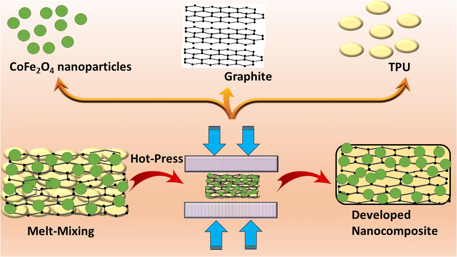 | ||
| Fig. 1 Schematic representation of the preparation of the developed GF–TPU nanocomposites. | ||
3. Characterization
The X-ray Diffraction (XRD) of CoFe2O4 nanoparticles, graphite, and GF–TPU-based nanocomposites was investigated using a Rigaku MiniFlex 600 (Rigaku Corporation, Tokyo, Japan) X-ray diffractometer. Transmission electron microscopy (TEM) and high-resolution TEM (HR-TEM) were used to examine the morphology and particle size of the synthesized CoFe2O4 nanoparticles using a JEM-2100Plus (Jeol, Tokyo, Japan). An FEI NanoSEM 450 (FEI Company, The Netherlands) was used to perform field emission scanning electron microscopy (FE-SEM) on the developed TPU-based nanocomposites. The Raman spectrum of CoFe2O4 nanoparticles and graphite was recorded using a Nicolet DXR Raman microscope (Thermo Fisher Scientific, Waltham, MA) at a laser excitation wavelength of 532 nm (Fig. S2(a) and (b) in the ESI†). An FTIR spectrometer (Nicolet 6700) (Thermo Scientific, Waltham, MA) in attenuated total reflectance mode was used to obtain the FTIR spectrum for the CoFe2O4 nanoparticles and graphite (Fig. S2(c) in the ESI†). A vibrating sample magnetometer (VSM, Model 7404, Lake Shore, Westerville, OH) was used to examine the magnetic properties of CoFe2O4 nanoparticles and their nanocomposites. Rectangular specimens were used to measure scattering parameters, complex permittivity, and complex permeability with an X-band (WR 90) waveguide and a PNA-L network analyzer (Agilent N5230A) over a frequency range of 8.2–12.4 GHz. The recorded scattering parameters in the X-band frequency range were used to calculate the electromagnetic shielding effectiveness. The Nicolson–Ross–Weir technique was used to calculate complex permittivity and permeability. TGA measurements were performed in a nitrogen atmosphere using a Setaram LabSys Evo with a TG/DSC sensor from 25 to 1000 °C at 10 °C min−1 (Fig. S3 in the ESI†). The mechanical measurements of pure TPU and the developed GF15–TPU nanocomposite were examined by using a Testometric universal-testing machine of type M 350-5CT (Testometric Co. Ltd., Rochdale, UK) (Fig. S6 in the ESI†).4. Results and discussion
4.1 XRD study
The phase formation of CoFe2O4 nanoparticles was studied using X-ray diffraction. The XRD pattern of CoFe2O4 nanoparticles is depicted in Fig. 2(a), with characteristic peaks at 2θ = 18.4°, 30.2°, 35.5°, 37°, 43.1°, 53.5°, 57°, and 62.7° attributed to the (111), (220), (311), (222), (400), (422), (511), and (440) planes, respectively.31 This confirmed the successful formation of face-centered cubic spinel ferrite crystalline CoFe2O4 nanoparticles. The XRD pattern revealed no secondary phases or impurities, demonstrating the nanoparticles' high purity and crystallinity. The crystallite size was also determined using the well-known Debye–Scherrer equation for the most intense (311) reflection, which was 12.6 nm. Furthermore, the lattice constant (a) for face-centered cubic crystals was calculated using the following expression:32where the Miller indices are represented by h, k, and l. The lattice constant of CoFe2O4 nanoparticles was found to be 8.37 Å. The XRD pattern of graphite is displayed in Fig. 2(b). There was a sharp peak at 26.5° corresponding to the graphitic structure (002) plane and another diffraction peak at 54.7° corresponding to the (004) plane.33,34 In addition, Fig. 2(c) shows the XRD pattern of the developed GF–TPU nanocomposites. The presence of graphite was also detected, with a highly intense peak attributed to the (002) and (004) planes.35 However, in the case of XRD of the developed polymer nanocomposites, the intensity of graphite peaks was reduced, compared to the intensity of pure graphite peaks, which is due to the interaction of the CoFe2O4 nanoparticles with graphite in the TPU matrix. With the incorporation of CoFe2O4 nanoparticles, there is a possibility of hindrance in restacking of graphitic layers resulting in a reduced intensity of the XRD peaks of graphite in the developed GF–TPU nanocomposites. Joy et al.36 also previously reported a decrease in the XRD intensity peak of graphene oxide after decoration with gold nanostructures (GO–Au) into a polycaprolactone (PCL) matrix. Furthermore, Fig. 2(d) shows the magnified XRD pattern of the developed nanocomposites. The XRD diffraction peaks corresponding to the (111), (220), (311), (222), (400), (422), (511), and (440) planes were also observed in the developed nanocomposites, confirming the successful incorporation of CoFe2O4 nanoparticles. Also, the presence of TPU was detected at 23° in all the developed nanocomposites, corresponding to the TPU's hard segments.37,38

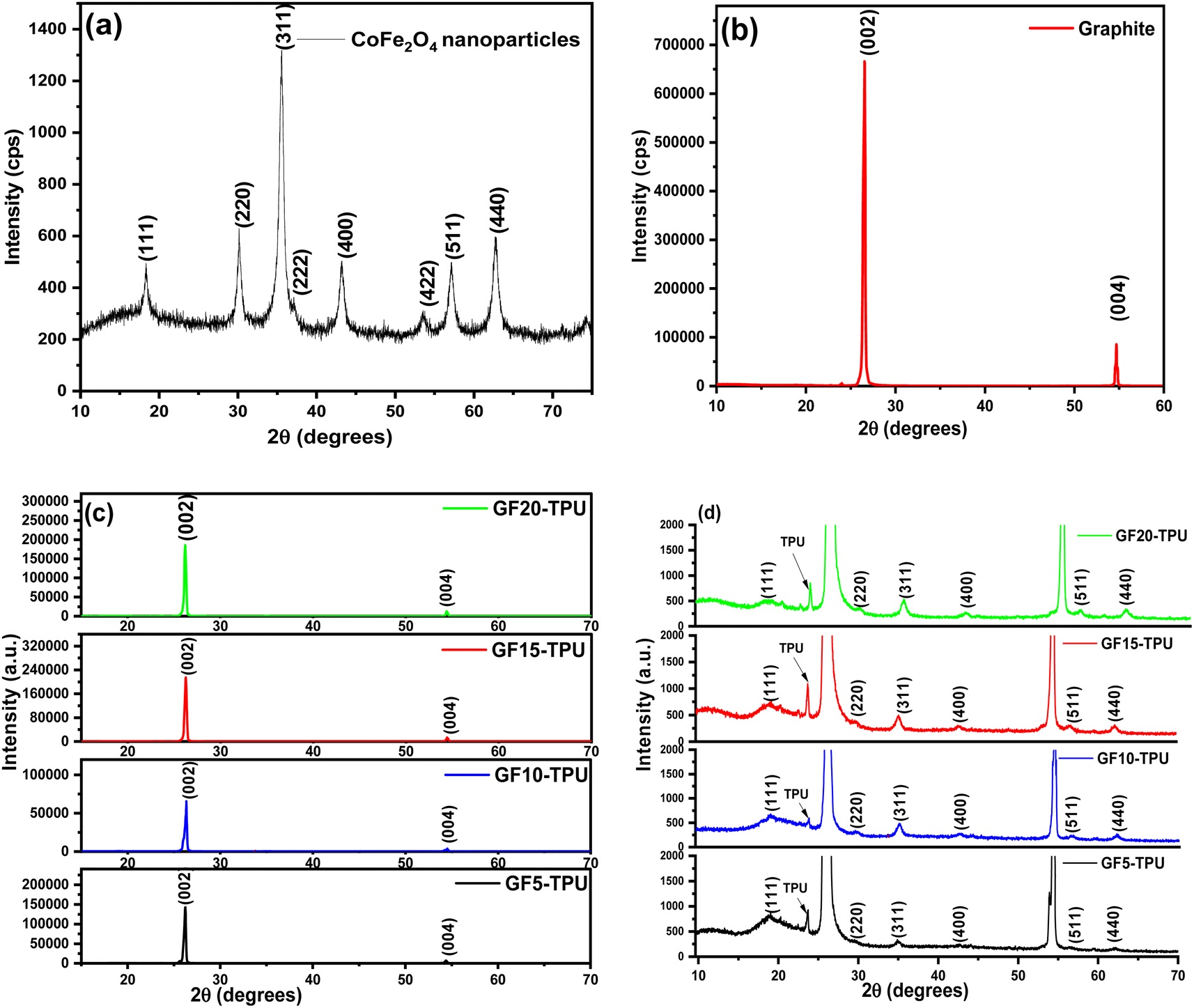 | ||
| Fig. 2 XRD pattern of (a) CoFe2O4 nanoparticles, (b) graphite, (c) all the developed GF–TPU nanocomposites; and (d) magnified XRD pattern of all the developed GF–TPU nanocomposites. | ||
4.2 TEM and HRTEM study of CoFe2O4 nanoparticles
Fig. 3(a) shows the TEM and HRTEM micrographs of CoFe2O4 nanoparticles. The nanoparticles were spherical like, as seen in Fig. 3(a). The diameter of the CoFe2O4 nanoparticles was measured to be 7.3 nm on average, as shown in Fig. 3(b). The HRTEM images of CoFe2O4 nanoparticles in Fig. 3(c) show lattice fringes with evaluated spacings between two fringes dhkl of 0.25 nm, 0.45 nm, and 0.28 nm corresponding to the (311), (111), and (220) planes, indicating good crystallinity of the nanoparticles formed.39–41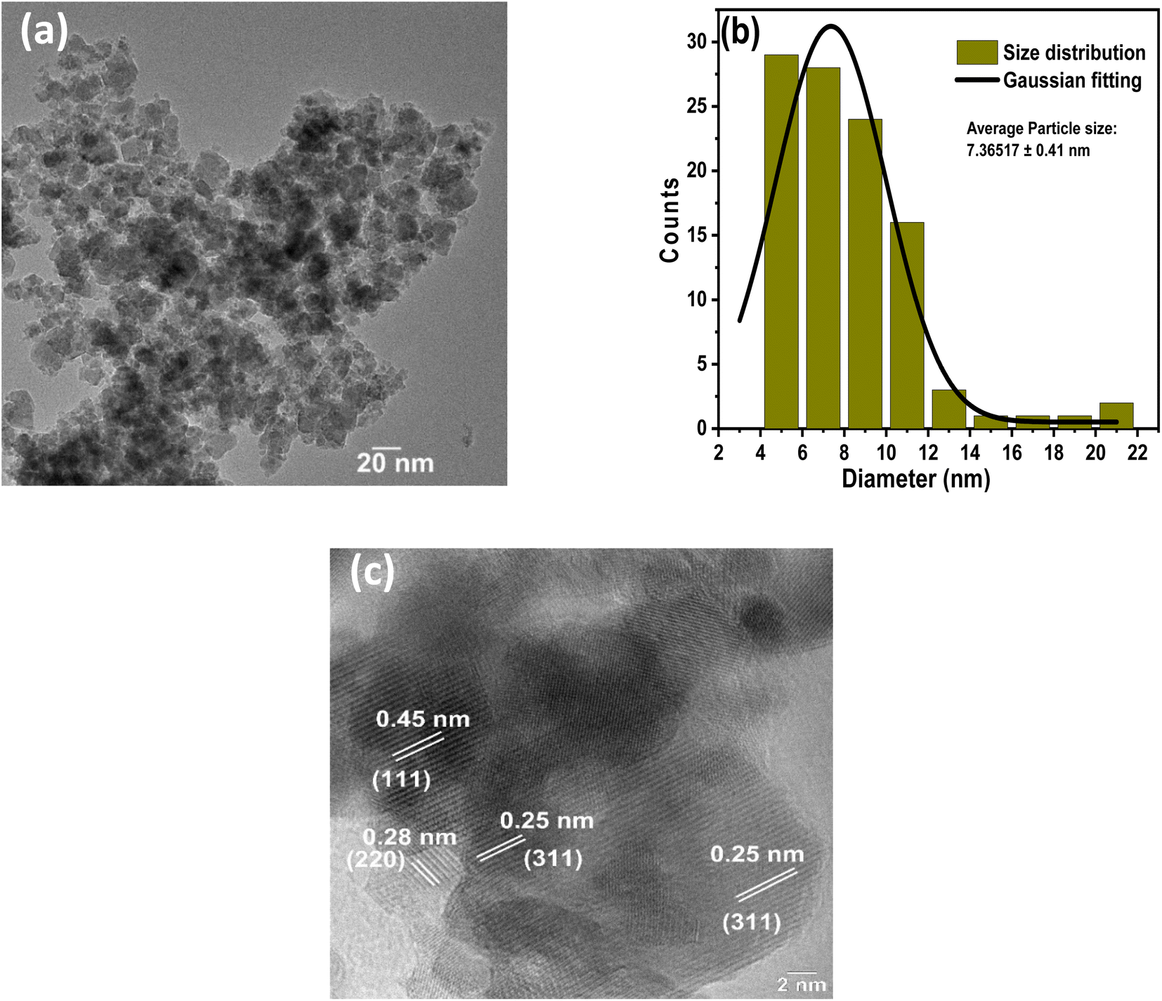 | ||
| Fig. 3 (a) TEM of the CoFe2O4 nanoparticles, (b) particle size distribution for CoFe2O4 nanoparticles, and (c) HRTEM of the CoFe2O4 nanoparticles. | ||
4.3 FE-SEM and EDAX of the nanocomposites
The surface structure, morphology, and dispersion of the fillers within the prepared nanocomposites were evaluated using FE-SEM. Fig. 4(a) and (b) portray the SEM micrographs of the GF15–TPU and GF20–TPU nanocomposites, respectively. The spherical-shaped CoFe2O4 nanoparticles were distributed throughout the TPU matrix, as seen. The presence of graphite can be seen in the TPU matrix as well. As a result, the presence of both fillers inside the nanocomposite was confirmed by FE-SEM. Further the FE-SEM micrographs of GF5–TPU and GF10–TPU nanocomposites are demonstrated in Fig. S4(a) and (b) in the ESI.†Fig. 4(c) also shows the energy-dispersive X-ray analysis (EDAX) of GF20–TPU, which confirmed the presence of Co, Fe, O, and C within the nanocomposite system.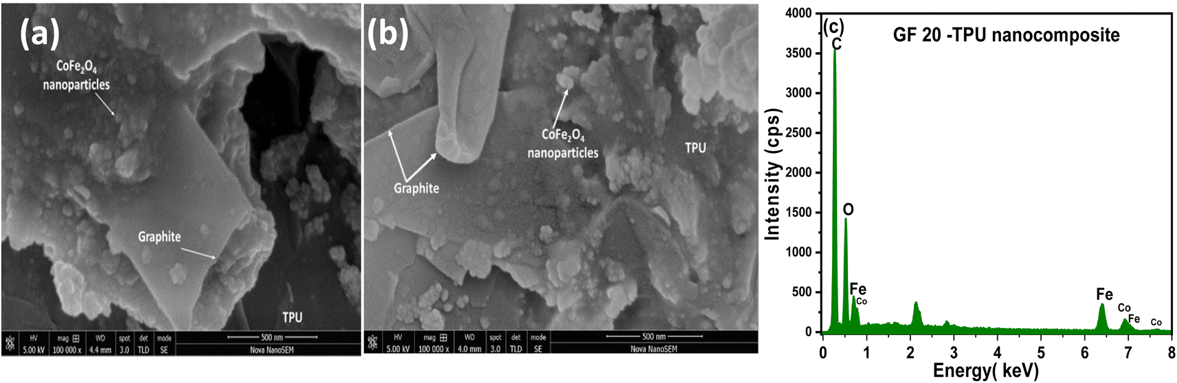 | ||
| Fig. 4 FE-SEM micrograph of the (a) GF15–TPU nanocomposite and (b) GF20–TPU nanocomposite, and (c) EDAX spectrum for the GF20–TPU nanocomposite. | ||
4.4 Magnetic properties of CoFe2O4 nanoparticles and their nanocomposite
Fig. 5(a) shows the magnetic hysteresis curve of the synthesized CoFe2O4 nanoparticles at room temperature in an applied magnetic field of up to 10 kOe extracted from the VSM instrument. The inset plot depicts a more expanded region of the M–H curve for greater clarity on CoFe2O4 nanoparticle coercivity (Hc) and remanent magnetization (Mr). As can be seen, the saturation magnetization (Ms) value for CoFe2O4 nanoparticles was 49.5 emu g−1. Furthermore, the coercivity (Hc) value was 14.42 Oe and the remanent magnetization (Mr) value was 3.9 emu g−1, indicating that the nanoparticles were ferromagnetic. Fig. 5(b) also shows the M–H curves of the developed GF5–TPU, GF15–TPU, and GF20–TPU nanocomposites. The inset plot in Fig. 5(b) is an enlarged view of the nanocomposites' M–H curve. The magnetic parameters, including saturation magnetization (Ms), coercivity (Hc) and remanent magnetization (Mr), were evaluated and are presented in Table 1. As a consequence of the incorporation of CoFe2O4 nanoparticles with graphite in the TPU polymer matrix, the saturation magnetization was decreased from 49.5 emu g−1 to 4.5 emu g−1 for the GF5–TPU nanocomposite as a non-magnetic TPU matrix and graphite doesn't contribute to the magnetization of the nanocomposites. In comparison to nanoparticles, Akyol et al.42 observed a similar decrease in saturation magnetization for polyaniline-coated Y3Fe5O12/NiFe2O4 hybrid composites. According to the expression Ms = ϕms, the value of saturation magnetization Ms relies mainly on the volume fraction of the ferrites, ϕ, and the saturation moment of a single particle (ms).43 Therefore, the saturation magnetization value was further improved with increased wt% of CoFe2O4 nanoparticles inside the nanocomposites up to 11.9 emu g−1. The value of remanent magnetization Mr was decreased for the GF5–TPU nanocomposite with respect to pure CoFe2O4 nanoparticles.44 Interestingly, increasing the content of CoFe2O4 nanoparticles in the developed nanocomposites improved remanent magnetization (Mr). Furthermore, the coercivity (Hc) value of the nanocomposites increased significantly when compared to pure CoFe2O4 nanoparticles, rising from 14.4 Oe to 588.8 Oe. This can be attributed to the extra anisotropy contributed by the polymer and enhancement in dipolar interactions.45 | ||
| Fig. 5 Magnetic hysteresis (M–H) curve of (a) the synthesized CoFe2O4 nanoparticles and (b) the developed GF–TPU nanocomposites. | ||
| Sample | M s (emu g−1) | H c (Oe) | M r (emu g−1) |
|---|---|---|---|
| CoFe2O4 nanoparticles | 49.5 | 14.4 | 3.9 |
| GF5–TPU nanocomposite | 4.5 | 553.6 | 1.2 |
| GF15–TPU nanocomposite | 6.3 | 567.6 | 1.8 |
| GF20–TPU nanocomposite | 11.9 | 588.8 | 3.5 |
4.5 EMI shielding effectiveness
EMI shielding is represented in terms of electromagnetic interference (EMI) shielding effectiveness. It is defined as a logarithmic term of the ratio of incident power, Pi, to the transmitted power, Pt, of the EM wave and is measured in decibels (dB). The EMI shielding effectiveness can be expressed as follows:46
The higher the value of total EMI shielding effectiveness (SET), the less the transmission of EM waves through the shielding material. Based on Schelkunoff's theory, the total EMI shielding effectiveness, SET, is the contribution of the sum of shielding effectiveness due to reflection, SER, shielding effectiveness due to absorption, SEA and shielding effectiveness due to multiple reflections, SEM, and can be represented as follows:47
| SET = SEA + SER + SEM |
Remarkably, when the value of SEA > 10 dB, the effect of SEM is considered insignificant. This is due to the negligible amplitude of the EM waves first reaching the second interface. The reflection and absorption diminished the multiple times reflected EM energy.48 Therefore, SET can be expressed as follows:
| SET = SEA + SER |
The value of SET, SEA and SER can be evaluated from scattering parameters extracted from the vector network analyzer using the following expressions:
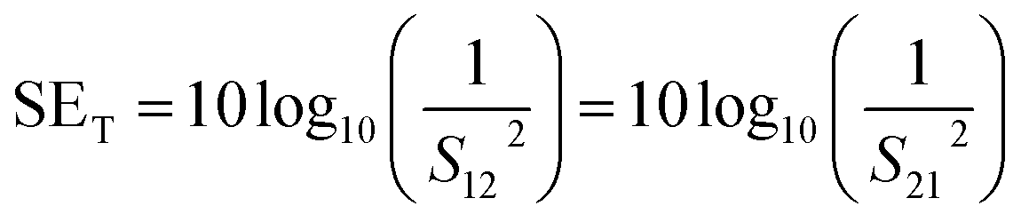

where S11, S12, S21, and S22 refer to the forward reflection coefficient, forward transmission coefficient, backward transmission coefficient, and reverse reflection coefficient, respectively.

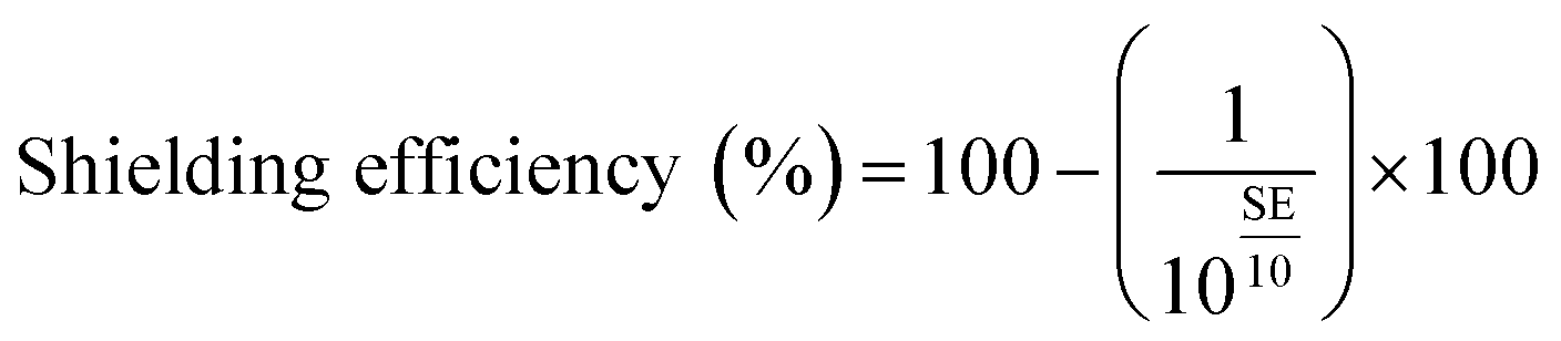
Fig. 6(a) illustrates the plot of SET for different compositions of the developed TPU-based nanocomposites having 5 mm thickness in the 8.2–12.4 GHz frequency range. It can be observed that the GF15–TPU nanocomposite exhibited a value reaching up to 41.5 dB. The maximum value of SET was 17.5 dB, 26.9 dB, 41.5 dB, and 41.2 dB for GF5–TPU, GF10–TPU, GF15–TPU, and GF20–TPU, respectively. It was noticed that the value of SET was varied with the variation in the loading wt% of cobalt ferrite nanoparticles and graphite fillers inside the TPU nanocomposites. It can be noticed that the combination of CoFe2O4 nanoparticles and graphite in the TPU matrix has provided the improved value of maximum shielding effectiveness of the nanocomposites. The GF5–TPU nanocomposites displayed the lowest EMI shielding performance among all the developed nanocomposites; however, GF15–TPU showed the highest EMI shielding performance associated with synergistic enhancement. The enhancement in the value of SET with the increase in wt% of CoFe2O4 nanoparticles inside the nanocomposites directs towards the enhancement in the losses due to absorption and multiple reflections of EM waves.49 In addition, in the case of sample GF20–TPU, the value of SET was noticed to be slightly declined with a further increase in wt% of CoFe2O4 nanoparticles inside the nanocomposites. Fig. S5 in the ESI† file displays the SET, SEA, and SER for the developed nanocomposites with 4 mm thickness as a function of frequency. A similar trend was noticed for the enhancement in the EMI shielding effectiveness value for the developed nanocomposites with 4 mm thickness. Since the EMI shielding ≥ 20 dB corresponds to 99% attenuation of EM wave radiation, it is suitable for commercial applications.50 Considering this, the shielding efficiency was evaluated by using the following expression:51
 | ||
| Fig. 6 EMI (a) total shielding effectiveness, SET, (b) shielding due to absorption, SEA, and (c) shielding due to reflection SER as a function of frequency in the X-band range for the developed nanocomposites. | ||
Remarkably, the GF15–TPU nanocomposite possessed up to 99.993% shielding efficiency, signifying only 0.007% transmission of EM waves. To understand further clearly the EMI shielding mechanism, shielding due to absorption SEA was also evaluated for different compositions and is represented in Fig. 6(b). The value of SEA was 13.9 dB, 22.7 dB, 38.1 dB, and 33.9 dB for GF5–TPU, GF10–TPU, GF15–TPU, and GF20–TPU, respectively. It can be noticed that the GF15–TPU nanocomposite exhibited the value of SEA significantly enhanced up to 38.1 dB. Further, the value of shielding due to reflection, SER, from Fig. 6(c) was 5.9 dB, 5.6 dB, 3.8 dB, and 9 dB for GF5–TPU, GF10–TPU, GF15–TPU, and GF20–TPU, respectively. This concludes that shielding due to reflection (SER) had less contribution to the total EMI shielding (SET) of the prepared nanocomposites. Furthermore, Fig. 7(a) depicts the comparison plot of SEA, SER and SET for all the developed nanocomposites.
 | ||
| Fig. 7 (a) The comparison plot of the contribution of SEA, SER and SET for the developed GF–TPU nanocomposites, (b) power coefficients for the GF15–TPU nanocomposite, and (c) Aeff of the developed GF–TPU nanocomposites as a function of frequency. | ||
To study the EMI shielding mechanism, the reflection coefficient (R), transmission coefficient (T) and absorption coefficient (A), which describe a material's capacity to reflect, absorb, and transmit microwaves, were evaluated for the developed GF15–TPU nanocomposite using the following expression from the scattering parameters extracted from VNA:52
| R = |S11|2 = |S22|2 |
| T = |S12|2 = |S21|2 |
| A = 1 − R − T |
Although certain researchers have reported the EMI shielding mechanism based on SEA and SER, it is still worth noting that only a comparison of the SER and SEA values is insufficient to infer the shielding mechanism.9Fig. 7(b) illustrates the plot of R, A and T for the developed GF15–TPU nanocomposite. It was noticed that the GF15–TPU nanocomposite exhibits higher values of reflection coefficient (R) than absorption coefficient (A). However, from 8.2 GHz to 8.9 GHz, an enhancement in the value of the absorption coefficient (from 0.40 to 0.46) along with a decline in the reflection coefficient (R) (from 0.59 to 0.53) was noticed. Further, at a frequency of 10.7 GHz, the value of absorption reached the highest value of 0.48 while the reflection coefficient was reduced to 0.51, thereby making an almost equal contribution from the reflection coefficient and the absorption coefficient. However, the value of R was always greater than that of A over the entire frequency range. The slightly higher value of R than A can be associated with a slight impedance mismatch induced between the air and the nanocomposite owing to the high conductivity of the GF15–TPU nanocomposite.53 It was noticed that the values of SEA were much higher than those of SER for the GF15–TPU nanocomposite, whereas the value of power coefficient R was greater than that of A over the whole frequency range. This discrepancy in results reveals that the power coefficients are quantitative characteristics of the incident EM wave on the shielding material, whereas SEA and SER demonstrate the EM waves that penetrated the shielding material.54 Since reflection occurs rapidly as soon as EM waves are incident on the EMI shielding material, it is possible that at that stage, the EMI shielding mechanism was reflection-dominant; however, once the EM waves penetrated inside the EMI shielding material, the EMI shielding mechanism becomes absorption-dominant.55
In addition, the effective absorption (Aeff), which signifies the quantity of power absorbed by the shielding material, was also investigated. The effective absorption (Aeff) percentage can be evaluated using the following equation:52

Fig. 7(c) represents the variation of Aeff (%) of all the nanocomposites with frequency. Remarkably, the GF15–TPU nanocomposite displayed the highest 99.8% effective absorption efficiency.
P. L. Rathi et al.56 fabricated triphasic composite films with Sn0.2Fe2.8O4–graphite in PVDF possessing different percentages of conducting and magnetic components and reported EMI shielding effectiveness up to 30 dB in the 8–12 GHz frequency range. Further, PVDF/CoFe2O4@CNTs composites were developed by Kazmi et al.57 with an EMI shielding of 12.68 dB for 7 wt% CFO@CNTs hybrids in a PVDF matrix in the 8–18 GHz frequency range. Furthermore, Ma et al.58 demonstrated an EMI shielding effectiveness of 33.8 dB in the X-band frequency range for glass fiber mat reinforced thermoplastics (GMT)/polyacrylate expandable foam particles (PEFP)/graphite nanoplatelet (GNP) composites. Pradhan et al.59 reported the development of polycarbonate (PC) based nanocomposites with graphite flakes (GF) and multi-walled carbon nanotubes (MWCNT) as fillers and noticed a maximum EMI shielding of 35 dB in the X-band frequency range. Another research group, Kaushal et al.,60 developed graphite-reinforced polypropylene (PGP) composites and displayed an EMI shielding effectiveness value of 10.3 dB in the 8–12 GHz frequency range. Table 2 represents EMI shielding performances of developed nanocomposites as reported in the literature by other researchers.
| S. no. | Nanocomposite | SET (dB) | Frequency (GHz) | Reference |
|---|---|---|---|---|
| 1 | Sn0.2Fe2.8O4–graphite–PVDF nanocomposite films | 30 dB | 8–12 GHz | 56 |
| 2 | PVDF/CoFe2O4@CNTs composites | 12.68 dB | 8–18 GHz | 57 |
| 3 | GMT/PEFP/GNP composites | 33.8 dB | 8–12 GHz | 58 |
| 4 | Graphite flake (GF)–multi-walled carbon nanotube (MWCNT)–polycarbonate (PC) nanocomposite | 35 dB | 8–12 GHz | 59 |
| 5 | Graphite-reinforced polypropylene (PGP) composites | 10.30 dB | 8–12 GHz | 60 |
| 6 | CoFe2O4–graphite–TPU nanocomposites | 41.5 dB | 8–12 GHz | This work |
 | ||
| Fig. 8 The variation of SET with tuned thickness as a function of frequency for the developed GF15–TPU nanocomposites. | ||
4.6 Electromagnetic parameter study
Fig. 9(a) illustrates the variation of the real part of the permittivity ε′ as a function of the frequency. The maximum value of ε′ was found to be 29.8, 35.1, 61.1 and 32.7 for GF5–TPU, GF10–TPU, GF15–TPU, and GF20–TPU nanocomposites, respectively. Remarkably, the GF15–TPU nanocomposite was noticed to be having a significantly larger value of ε′ compared to all the other nanocomposites, thus signifying the more substantial energy storage characteristics. The enhancement in the ε′ value with optimum concentration of CoFe2O4 nanoparticles with graphite aims towards the promoting effect of dielectric parameters. The increase in the value of ε′ is attributed to the interfaces arising between graphite and CoFe2O4 nanoparticles in the TPU polymer, which results in the accumulation of polarization charges. Further, these accumulations of charge carriers at the interfaces of CoFe2O4 nanoparticles and graphite result in an increase in the interfacial area.63 The increase in the interfacial area will suggest an enhancement in the energy storage capacity and further absorption characteristics of the polymer nanocomposites.6,64
 | ||
| Fig. 9 (a) The real part of the permittivity ε′, (b) imaginary part of permittivity ε′′ as a function of the frequency, (c) Cole–Cole plot, and (d) a.c. conductivity σac as a function of frequency for all the developed GF–TPU nanocomposites. | ||
Further, Fig. 9(b) illustrates the imaginary part of the permittivity ε′′ as a function of the frequency. As can be seen, the value of ε′′ was found to be 7.9, 11.1, 35.4 and 18.0 for the developed GF5–TPU, GF10–TPU, GF15–TPU, and GF20–TPU nanocomposites, respectively. Incredibly, the GF15–TPU nanocomposite displayed the highest value of ε′′ accompanied with noticeable relaxation peaks among all the nanocomposites. The appearance of relaxation peaks in the ε′′–f plot suggests the role of the polarization relaxation mechanism involved in the GF15–TPU nanocomposite.

where ε∞ is the relative dielectric permittivity at infinite frequency, εs is the static dielectric permittivity, ω represents angular frequency, and τ stands for the polarization relaxation time, respectively. Further, ignoring the role of σ in ε′′ and the elimination of ωτ, the equation between ε′ and ε′′ can be rewritten as follows:
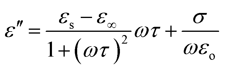
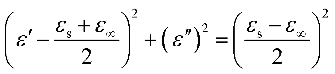
According to the above equation, each semi-circle in the ε′′–ε′ plot signifies one Cole–Cole semicircle, which attests to a Debye dipolar relaxation. Fig. 9(c) demonstrates the Cole–Cole plot for the developed nanocomposites. Several multiple cumulative semicircles were noticed for the developed nanocomposites.66 With an increase in the concentration up to 15 wt% of CoFe2O4 nanoparticles with 35 wt% graphite inside the polymer nanocomposites, the Cole–Cole semicircles were noticed to move to higher values in the ε′′–ε′ plot, which suggests the enhancement in the dielectric losses inside the nanocomposites.67,68 These relaxations might originate due to the presence of CoFe2O4 nanoparticles and graphite and their interfacial polarization inside the polymer nanocomposites.69
where σac stands for the electrical conductivity, ε0 is the absolute permittivity of the vacuum, and f denotes the frequency of the EM waves. Fig. 9(d) demonstrates the variation in electrical conductivity σac as a function of frequency. As can be seen, the maximum value of σac was 0.03 S cm−1, 0.07 S cm−1, 0.2 S cm−1, and 0.08 S cm−1 for the GF5–TPU, GF10–TPU, GF15–TPU, and GF20–TPU nanocomposites, respectively. The value of σac was noted to be highest for the GF15–TPU nanocomposite which possessed 15 wt% CoFe2O4 nanoparticles and 35 wt% graphite. It was noticed that with a further increase in the wt% of CoFe2O4 nanoparticles and, consequently, a decrease in the wt% of graphite in the nanocomposite, the value of σac didn't increase which can be associated with developing a percolation network at the optimum wt% for the GF15–TPU nanocomposite.70,71 As the concentration of CoFe2O4 was further increased, there might be a decrease in the formation of conducting channels owing to the reduction of the graphite particles.72 Due to the high concentration of CoFe2O4 nanoparticles inside the TPU matrix, the separation between the graphite particles might increase. Furthermore, cluster formation of CoFe2O4 nanoparticles at specific points might also have led to the increase in the spacing between graphite, which was responsible for interrupting the conductive network. Therefore, the value of conductivity was reduced at higher fraction loading of CoFe2O4 nanoparticles.73,74

 | ||
Fig. 10 (a) The real part of the permeability μ′, (b) the imaginary part of permeability μ′′, (c) dielectric loss, tan![[thin space (1/6-em)]](https://www.rsc.org/images/entities/char_2009.gif) δε, and (d) magnetic loss, tanδμ, as a function of the frequency for all the developed GF–TPU nanocomposites. δε, and (d) magnetic loss, tanδμ, as a function of the frequency for all the developed GF–TPU nanocomposites. | ||
δε = ε′′/ε′) and magnetic loss (tanδμ = μ′′/μ′) was also evaluated and plotted as a function of frequency in Fig. 10(c) and (d). The maximum value of tanδε from Fig. 10(c) was 0.26, 0.32, 0.61, and 0.56 for the GF5–TPU, GF10–TPU, GF15–TPU, and GF20–TPU nanocomposites, respectively. The ability of a material to convert stored energy into heat, or the extent to which an electrical field may penetrate in the material, is demonstrated by the dielectric loss tangent.
Incredibly the GF15–TPU nanocomposite demonstrated the highest dielectric loss among all the developed nanocomposites. The higher value of losses arises due to the presence of two distinct phases in the composite system.76 According to the free electron theory, the enhanced conductivity of the nanocomposite can also significantly improve the EM loss capacity inside the nanocomposites.77 In addition, the presence of graphite can introduce interfaces between CoFe2O4 nanoparticles and graphite led to the accumulation of charge and therefore it enhanced the EM wave dissipation ability. Moreover, the noticeable relaxation peaks in the case of the GF15–TPU nanocomposite also contribute to the EM wave absorption inside the nanocomposite.
Further, the value of tanδμ from Fig. 10(d) was noticed to be varied with varying wt% of CoFe2O4 nanoparticles and graphite inside the matrix. The polymer nanocomposite with CoFe2O4 nanoparticles–graphite wt% of 15/35 exhibited the highest value of magnetic loss compared with the other wt% of all the nanocomposites. The enhanced values of the dielectric and magnetic losses of the GF15–TPU nanocomposite further enhanced the shielding due to absorption in this nanocomposite.78,79 The synergistic effect of dielectric loss and magnetic loss ensures that the GF15–TPU nanocomposite exhibits high EM wave shielding performance.80,81
The magnetic loss of the EM wave absorbing material is attributed to hysteresis losses, eddy current loss, natural resonance, and domain-wall resonance.82 However, hysteresis loss and domain wall resonance mostly appear at the low frequency range (MHz) and therefore can be considered negligible in the GHz range.82 Moreover, the high value of tanδε compared to tanδμ signifies the predominant dielectric loss in the developed nanocomposites.
| Co = μ′′(μ′)−2f−1 |
According to the above equation, if the magnetic loss is derived only due to eddy current, then the plot of Co remains unchanged with a change in frequency. However, if the value of Co is noticed to vary with the frequency, then the magnetic loss might be due to natural resonance and exchange resonance.83Fig. 11(a) demonstrates the correlative plot between Co and frequency for all the developed nanocomposites. It was noticed that the value of Co remained nearly stable in the frequency range from 8.5 GHz to 8.8 GHz, then from 9.9 to 10.1 GHz, further 11.1 to 11.5 GHz, and furthermore from 11.8 GHz to 12.3 GHz for the developed nanocomposites. In addition, some fluctuation peaks can also be noticed for the developed nanocomposites, which are consistent with the previously reported work.84 In general, natural resonance peaks are seen in the frequency range of 2–10 GHz, and exchange resonance peaks arise in the frequency range of 10–18 GHz.85,86 Therefore, it can be concluded that the magnetic losses might be a contribution from the eddy current loss, natural resonance, and exchange resonance.
 | ||
| Fig. 11 Variation of (a) eddy current loss, Co, (b) skin-depth, δ, (c) impedance matching coefficient, Z, and (d) attenuation constant, α, as a function of the frequency for all the developed GF–TPU nanocomposites. | ||
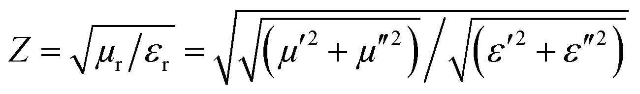
where μr denotes the permeability of the material, σ indicates electrical conductivity (S m−1) and f (Hz) is the frequency. Skin depth (δ) is an important aspect that must be taken into consideration when selecting the shielding material's thickness. The material will not be suitable for EMI shielding if the thickness of the shielding material is less than the skin depth of the material owing to the reflection of the incoming EM waves from the shielding material surface rather than absorption.87Fig. 11(b) illustrates the variation of δ as a function of frequency for all the developed nanocomposites. As can be seen, the value of skin depth (δ) decreases with an increase in the frequency from 6.07 μm to 5.0 μm, 5.8 μm to 3.0 μm, 2.9 μm to 1.9 μm and 4.5 μm to 2.9 μm, for the GF5–TPU, GF10–TPU, GF15–TPU and GF25–TPU, respectively. Interestingly, the GF15–TPU nanocomposite possessed the lowest skin depth among all the developed nanocomposites.

where Z denotes the impedance matching coefficient. Fig. 11(c) represents the plot of Z versus frequency for all the developed nanocomposites. The value of the impedance matching coefficient was observed to be in the range of 0.11–0.16 for the developed nanocomposites. The GF15–TPU nanocomposite was noticed to possess the lowest impedance matching coefficient. On considering the ideal impedance match value, which is close to 1, the impedance matching was observed to be matching at low wt% of CoFe2O4 nanoparticles and gradually mismatched at higher content (wt%) of CoFe2O4 nanoparticles except for the GF20–TPU nanocomposite. Though the value of Z was highest for the GF5–TPU nanocomposite, the EMI shielding performance for the GF5–TPU nanocomposite is not the best. However, impedance matching is not the only factor behind the nanocomposites' superior EMI shielding performance. The attenuation constant is utilized to analyze the energy conversion rate, which establishes the capacity for attenuation of EMI shielding materials. When an EM wave is incident on the shielding material, then the magnitude and the phase of the EM wave decrease exponentially according to the following expression:89
where γs denotes the propagation factor, ω represents angular frequency, γs in the above expression is a complex number, and the real part of it is called the attenuation constant (α). Considering this, the attenuation constant was evaluated for all the developed nanocomposites as a function of frequency using the following expression:89


Fig. 11(d) demonstrates the plot of attenuation constant as a function of frequency for all the developed nanocomposites. The GF15–TPU nanocomposite was spotted to possess the highest value of the attenuation constant among all the developed nanocomposites and therefore revealed high dielectric and magnetic loss capabilities. The impedance mismatching and high attenuation constant are due to much higher permittivity as compared with the permeability of the GF15–TPU nanocomposite. Otherwise, if the absorbing material's attenuation capacity is insufficient, the forward wave will not attenuate entirely and can transmit right through it. The poor impedance matching and high attenuation constant for the GF15–TPU nanocomposite confirm that the EM waves are more likely to be reflected, but then they can be successfully dissipated once they have entered the interior of the nanocomposite. Chen et al.90 also observed the low impedance matching and high attenuation constant for Ti3C2Tx/Fe3O4 with an optimized EMI shielding performance. Similar findings support the hypothesis that, in contrast to impedance matching, the larger attenuation constant may play a key part in EMI shielding.83,91
A putative electromagnetic interference shielding mechanism behind the superior EMI shielding effectiveness based on the overall results and analysis is demonstrated in Fig. 12. In accordance with transmission line theory, as EM waves strike the EMI shielding material, due to the impedance mismatch at the sample–air interface, some of them are reflected, while others are absorbed and the remaining get transmitted. Generally, the improved EM shielding behavior is owing to the synergetic dielectric and magnetic losses between the fillers in the polymer composite. The presence of heterogeneous interfaces and numerous defects in CoFe2O4 nanoparticles and graphite serves as dipole or scattering centers inside the nanocomposite in the presence of the EM field.92 The existence of defects and multiple interfaces by formation of microcapacitor-like structures promoted a significantly enhanced dipolar polarization and interfacial polarization inside the nanocomposite and promoted EM wave attenuation.93 The structure of the nanocomposite provided a continuous conductive network, due to the presence of an optimum amount of graphite. Conduction loss was enhanced due to the hopping of electrons through defects by absorbing EM waves resulting in the facilitation of electron migration inside the nanocomposite.94–97 The alternate EM field led to the charge accumulation at the interface of conductive graphite, and CoFe2O4 nanoparticles occurred in the TPU matrix and further enhanced the interfacial polarization loss and improvement in EMI shielding performance. The introduction of magnetic CoFe2O4 nanoparticles can influence the magnetic losses which are associated with the natural resonance, exchange resonance, and eddy current loss, which are crucial components in enhancing EM wave absorption.57,98 Further, the conducting channel of graphite and existence of magnetic filler CoFe2O4 nanoparticles results in multiple internal reflections, scattering of residual EM waves, and absorption inside the nanocomposite sheet which prolongs the path length of the propagation of EM waves, therefore resulting in the attenuation of EM waves to a great extent.99–102 The large electrical conductivity differences between TPU and fillers, such as graphite and CoFe2O4 nanoparticles, result in a considerable improvement in the attenuation constant.103 Overall, the synergic dielectric and magnetic losses, dipole and interfacial polarization, conduction loss, eddy current loss, natural resonance, and high attenuation constant play a significant role in the absorption of incoming EM waves and enhancement of EMI shielding properties.
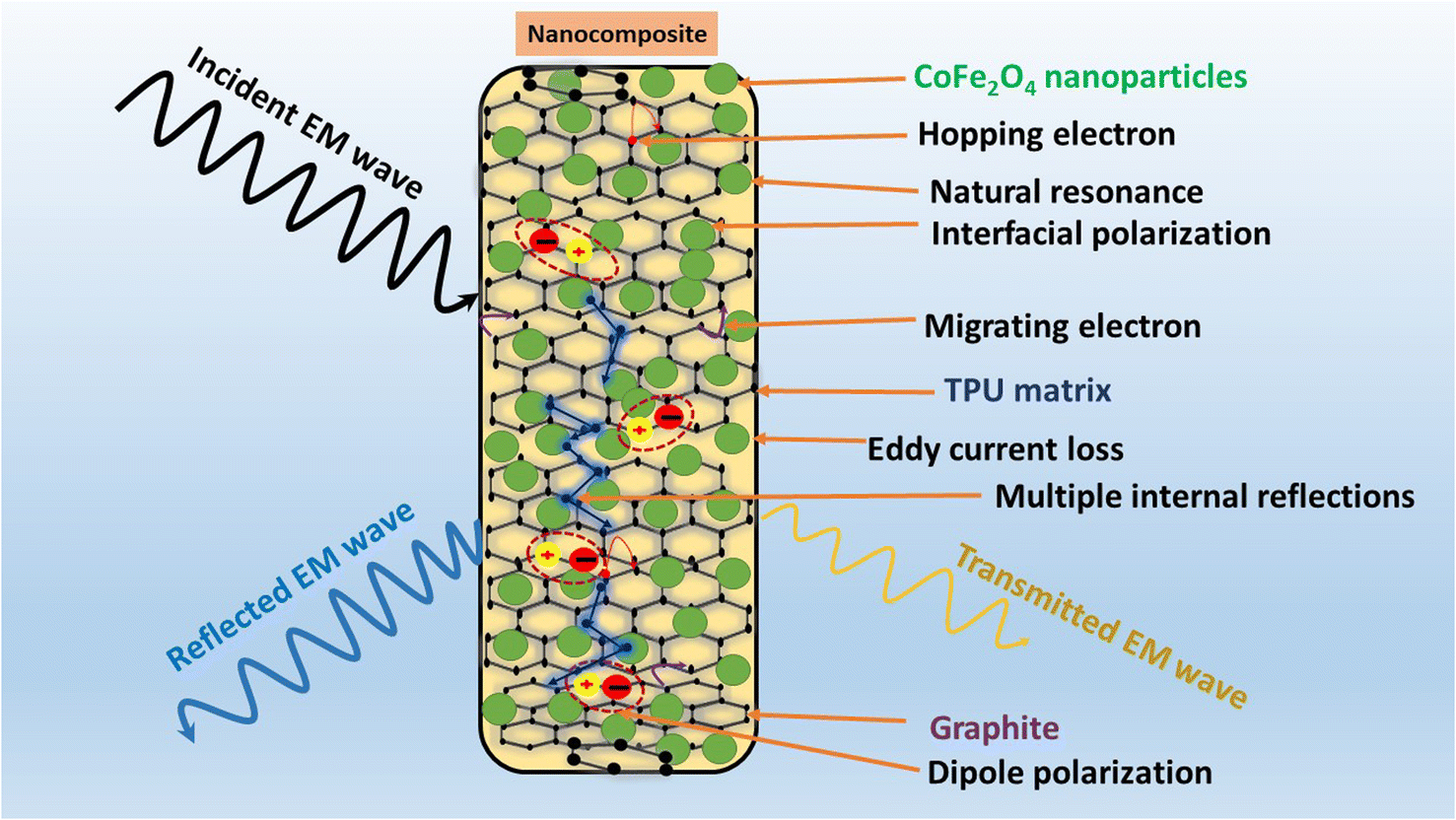 | ||
| Fig. 12 A putative EMI shielding mechanism behind the superior EMI performance of the developed CoFe2O4 nanoparticles–graphite–TPU nanocomposite. | ||
5. Conclusion
This study evaluated an optimized polymer nanocomposite composed of an appropriate concentration of graphite and CoFe2O4 nanoparticles in the TPU matrix. In this work, various nanocomposites with different wt% of CoFe2O4 nanoparticles and graphite in the TPU matrix using the melt-mixing approach were successfully designed. The structural, morphological, and magnetic characteristics of the CoFe2O4 nanoparticles and the nanocomposites were evaluated in detail. Benefiting from the optimum amount of electrical filler graphite and magnetic filler CoFe2O4 nanoparticles, the developed polymer nanocomposite with 35 wt% graphite and 15 wt% CoFe2O4 nanoparticles in the TPU matrix designated as GF15–TPU demonstrated the highest EMI shielding performance of 41.5 dB possessing 99.993% shielding efficiency among all the developed nanocomposites. The variation of SET as a function of frequency with tuned thickness for 1 mm, 2 mm, 4 mm and 5 mm for the developed GF15–TPU nanocomposites is also investigated and was found to vary from 17.5 dB to 41.5 dB. The enhanced EMI shielding of the GF15–TPU nanocomposite is attributed to the improved absorption and less reflections of EM waves inside the nanocomposite system owing to the synergic dielectric and magnetic losses, eddy current loss, high attenuation, interfacial polarizations, and multiple scattering. This simpler, straight-forward, economical, and innovative report based on the optimized wt% of graphite and CoFe2O4 nanoparticles in the TPU matrix demonstrates superior EMI shielding characteristics and can be anticipated for commercial applications.Author contributions
Anju: methodology, data curation, formal analysis, writing – original draft, investigation. Milan Masař: data curation, formal analysis. Michal Machovský: data curation, formal analysis. Michal Urbánek: data curation, formal analysis. Pavol Šuly: data curation, formal analysis. Barbora Hanulíková: data curation, formal analysis. Jarmila Vilčáková: data curation, formal analysis, visualization. Ivo Kuřitka: visualization, project administration, funding acquisition. Raghvendra Singh Yadav: writing-review & editing, funding acquisition, supervision, conceptualization, methodology, investigation, funding acquisition, project administration.Conflicts of interest
The authors declare that they have no known competing financial interests that could have appeared to influence the work reported in this paper.Acknowledgements
This work was supported by the Ministry of Education, Youth, and Sports of the Czech Republic-DKRVO (RP/CPS/2022/007) at the Centre of Polymer Systems, Tomas Bata University in Zlin, Czech Republic. One author, Anju, acknowledges the financial support provided by the Internal Grant Agency (IGA/CPS/2023/006).References
- M. Kallumottakkal, M. I. Hussein and M. Z. Iqbal, Front. Mater., 2021, 8, 1–19 CrossRef.
- F. Ruiz-Perez, S. M. López-Estrada, R. V. Tolentino-Hernández and F. Caballero-Briones, J. Sci.: Adv. Mater. Devices, 2022, 7(3), 100454 CAS.
- R. Peymanfar, Z. S. Ershad, E. Selseleh-Zakerin and S. H. Tavassoli, Ceram. Int., 2022, 48, 16461–16476 CrossRef CAS.
- X. Zheng, H. Zhang, R. Jiang, Z. Liu, S. Zhu, W. Li, L. Jiang and X. Zhou, J. Colloid Interface Sci., 2023, 649, 279–289 CrossRef CAS PubMed.
- T. Peng, Y. Si, J. Qian, Z. Zhang, X. Yan, C. Zhu and X. Hong, Appl. Surf. Sci., 2023, 613, 156001 CrossRef CAS.
- M. Praveen, G. S. Karthikeya, R. H. Krishna, G. M. Mamatha, C. Manjunatha, A. Khosla and B. M. Nagabhushana, Diamond Relat. Mater., 2022, 130, 109501 CrossRef CAS.
- S. Javaria Kazmi, M. Nadeem, A. Younis, S. Loomba, B. Shabbir, S. Manzoor and S. Hussain, J. Magn. Magn. Mater., 2022, 563, 170037 CrossRef CAS.
- R. Li, S. Wang, P. Bai, B. Fan, B. Zhao and R. Zhang, Mater. Adv., 2021, 2, 718–727 RSC.
- B. Shen, Y. Li, W. Zhai and W. Zheng, ACS Appl. Mater. Interfaces, 2016, 8, 8050–8057 CrossRef CAS PubMed.
- Q. Zhang, D. Lin, B. Deng, X. Xu, Q. Nian, S. Jin, K. D. Leedy, H. Li and G. J. Cheng, Adv. Mater., 2017, 29, 1–12 Search PubMed.
- Y. Huang, K. Yasuda and C. Wan, ACS Appl. Mater. Interfaces, 2020, 12, 55148–55156 CrossRef CAS PubMed.
- S. E. Berrabah, A. Benchettara, F. Smaili, A. Benchettara and A. Mahieddine, J. Alloys Compd., 2023, 942, 169112 CrossRef CAS.
- D. Zhang, W. Zhang, S. Zhang, X. Ji and L. Li, J. Energy Storage, 2023, 60, 106678 CrossRef.
- Y. Zhang, B. Ye, G. Zhou, L. Li, W. Geng, L. Yao, F. Zhang, J. Xie, S. J. Park, Z. Yang and C. Huang, Composites, Part A, 2023, 167, 107414 CrossRef CAS.
- D. Li, B. Tang, D. Cheng, J. Wu, W. Tang, Z. Zhao, J. Li, G. Cai, J. Wang and X. Wang, Engineering, 2023, 21, 143–151 CrossRef CAS.
- S. Yang, Z. Jin, C. Song, Z. Pu and B. Wen, J. Mater. Sci., 2022, 57, 1084–1097 CrossRef CAS.
- R. Kumar, H. K. Choudhary, S. P. Pawar, S. Bose and B. Sahoo, Phys. Chem. Chem. Phys., 2017, 19, 23268–23279 RSC.
- C. K. Madhusudhan, K. Mahendra, B. S. Madhukar, T. E. Somesh and M. Faisal, Synth. Met., 2020, 267, 116450 CrossRef CAS.
- R. K. Bheema and K. C. Etika, J. Alloys Compd., 2023, 938, 168405 CrossRef CAS.
- Q. Han, X. Meng and C. Lu, J. Alloys Compd., 2018, 768, 742–749 CrossRef CAS.
- G. Zhang, R. Shu, Y. Xie, H. Xia, Y. Gan, J. Shi and J. He, Mater. Lett., 2018, 231, 209–212 CrossRef CAS.
- F. E. Carvalho, L. V. Lemos, A. C. C. Migliano, J. P. B. Machado and R. C. Pullar, Ceram. Int., 2018, 44, 915–921 CrossRef CAS.
- P. V. Ambuken, H. A. Stretz, J. H. Koo, J. M. Messman and D. Wong, Polym. Degrad. Stab., 2014, 102, 160–169 CrossRef CAS.
- A. Rostami and M. I. Moosavi, J. Appl. Polym. Sci., 2020, 137, 48520 CrossRef CAS.
- W. Wang, X. Liao, F. Guo, G. Wang, Z. Yan, F. Liu and G. Li, Ind. Eng. Chem. Res., 2020, 59, 7611–7623 CrossRef CAS.
- C. Liu, K. Xu, Y. Shi, J. Wang, S. Ma, Y. Feng, Y. Lv, F. Yang, M. Liu and P. Song, Mater. Today Phys., 2022, 22, 100607 CrossRef CAS.
- K. Chen, H. Wang, Y. Shi, M. Liu, Y. Feng, L. Fu and P. Song, J. Colloid Interface Sci., 2024, 653, 634–642 CrossRef CAS PubMed.
- Y. Shi, A. Yao, J. Han, H. Wang, Y. Feng, L. Fu, F. Yang and P. Song, J. Colloid Interface Sci., 2023, 640, 179–191 CrossRef CAS PubMed.
- D. Jiang, V. Murugadoss, Y. Wang, J. Lin, T. Ding, Z. Wang, Q. Shao, C. Wang, H. Liu, N. Lu, R. Wei, A. Subramania and Z. Guo, Polym. Rev., 2019, 59, 280–337 CrossRef CAS.
- Anju, R. S. Yadav, P. Pötschke, J. Pionteck, B. Krause, I. Kuřitka, J. Vilcakova, D. Skoda, P. Urbánek, M. Machovsky, M. Masař, M. Urbánek, M. Jurca, L. Kalina and J. Havlica, ACS Omega, 2021, 6, 28098–28118 CrossRef CAS PubMed.
- A. Modabberasl, T. Pirhoushyaran and S. H. Esmaeili-Faraj, Sci. Rep., 2022, 12, 1–11 CrossRef PubMed.
- M. Abdullah-Al-Mamun, M. S. I. Sarker, M. R. Hasan, M. M. Haque, F. A. Khan, M. M. Rahman and M. K. R. Khan, Results Phys., 2021, 29, 104698 CrossRef.
- J. Li, Y. Qin, Y. Chen, J. Shen, Y. Song and Z. Wang, Fuel, 2023, 333, 126334 CrossRef CAS.
- K. L. Saenger, J. C. Tsang, A. A. Bol, J. O. Chu, A. Grill and C. Lavoie, Appl. Phys. Lett., 2010, 96, 153105 CrossRef.
- J. Wang, M. Yi, Z. Shen, L. Liu, X. Zhang and S. Ma, J. Macromol. Sci., Part A: Pure Appl. Chem., 2019, 56, 733–740 CrossRef CAS.
- A. Joy, G. Unnikrishnan, M. Megha, M. Haris, J. Thomas, E. Kolanthai and M. Senthilkumar, Surf. Interfaces, 2023, 40, 103000 CrossRef CAS.
- X. Jing, H. Y. Mi, H. X. Huang and L. S. Turng, J. Mech. Behav. Biomed. Mater., 2016, 64, 94–103 CrossRef CAS PubMed.
- L. Yan, T. Xiong, Z. Zhang, H. Yang, X. Zhang, Y. He, J. Bian, H. Lin and D. Chen, J. Polym. Res., 2021, 1, 3 Search PubMed.
- D. Cao, L. Pan, J. Li, X. Cheng, Z. Zhao, J. Xu, Q. Li, X. Wang, S. Li, J. Wang and Q. Liu, Sci. Rep., 2018, 8, 1–9 CAS.
- S. Rana, K. K. Yadav, S. K. Guchhait, S. T. Nishanthi, S. K. Mehta and M. Jha, J. Mater. Sci., 2021, 56, 8383–8395 CrossRef CAS.
- B. Qiu, Y. Deng, M. Du, M. Xing and J. Zhang, Sci. Rep., 2016, 6, 1–10 CrossRef CAS PubMed.
- M. Akyol, C. Aka, O. İnözü, F. Ö. Alkurt and M. Karaaslan, J. Mater. Sci.: Mater. Electron., 2023, 34, 1–11 CrossRef.
- N. Gandhi, K. Singh, A. Ohlan, D. P. Singh and S. K. Dhawan, Compos. Sci. Technol., 2011, 71, 1754–1760 CrossRef CAS.
- R. A. Landa, J. J. Calvino, M. López-Haro and P. S. Antonel, Nano-Struct. Nano-Objects, 2021, 28, 100808 CrossRef CAS.
- A. Joshi and R. C. Srivastava, Mater. Today: Proc., 2023, 78, 774–779 CAS.
- M. P. Vidyashree, K. Sushmita, P. Nagarajan, M. K. Kokila and S. Bose, Chem. Eng. J. Adv., 2023, 13, 100430 CrossRef.
- Y. L. Dai, A. P. Guo, M. H. Gong, X. J. Zhang and B. Y. Wen, J. Colloid Interface Sci., 2023, 636, 492–500 CrossRef CAS PubMed.
- J. H. Lee, Y. S. Kim, H. J. Ru, S. Y. Lee and S. J. Park, Nano-Micro Lett., 2022, 14, 1–17 CrossRef PubMed.
- A. Gebrekrstos, S. Biswas, A. V. Menon, G. Madras, P. Pötschke and S. Bose, Composites, Part B, 2019, 166, 749–757 CrossRef CAS.
- X. Li, M. Yang, W. Qin, C. Gu, L. Feng, Z. Tian, H. Qiao, J. Chen, J. Chen and S. Yin, Colloids Surf., A, 2023, 658, 130706 CrossRef CAS.
- X. Liu, J. Wu, J. He and L. Zhang, Mater. Lett., 2017, 205, 261–263 CrossRef CAS.
- V. M. Serrato, V. Padilla, D. Jones, S. Herrera, L. Campos, I. Serrato, H. Foltz and K. Lozano, Polym. Compos., 2023, 44, 592–608 CrossRef CAS.
- Y. J. Wan, X. M. Li, P. L. Zhu, R. Sun, C. P. Wong and W. H. Liao, Composites, Part A, 2020, 130, 105764 CrossRef CAS.
- X. P. Zhang, L. C. Jia, G. Zhang, D. X. Yan and Z. M. Li, J. Mater. Chem. C, 2018, 6, 10760–10766 RSC.
- Z. Li, D. Feng, B. Li, D. Xie and Y. Mei, Compos. Sci. Technol., 2023, 231, 109803 CrossRef CAS.
- P. L. Rathi, B. Ponraj and S. Deepa, J. Phys. D Appl. Phys., 2021, 55, 095002 Search PubMed.
- S. J. Kazmi, M. Nadeem, M. A. Warsi, S. Manzoor, B. Shabbir and S. Hussain, J. Alloys Compd., 2022, 903, 163938 CrossRef CAS.
- M. Ma, L. Qiao, H. Yu, S. Chen, Y. Shi, H. He and X. Wang, J. Mater. Sci.: Mater. Electron., 2021, 32, 25863–25875 CrossRef CAS.
- S. S. Pradhan, L. Unnikrishnan, S. Mohanty and S. K. Nayak, Polym. Compos., 2021, 42, 4043–4055 CrossRef CAS.
- A. Kaushal and V. Singh, J. Electron. Mater., 2020, 49, 5293–5301 CrossRef CAS.
- B. Zhao, C. Zhao, M. Hamidinejad, C. Wang, R. Li, S. Wang, K. Yasamin and C. B. Park, J. Mater. Chem. C, 2018, 6, 10292–10300 RSC.
- A. Anju, R. S. Yadav, P. Pötschke, J. Pionteck, B. Krause, I. Kuřitka, J. Vilčáková, D. Škoda, P. Urbánek, M. Machovský, M. Masař and M. Urbánek, Int. J. Mol. Sci., 2022, 23, 2610 CrossRef PubMed.
- S. Dabas, M. Chahar and O. P. Thakur, Mater. Chem. Phys., 2022, 278, 125579 CrossRef CAS.
- M. Saini, R. Shukla and A. Kumar, J. Magn. Magn. Mater., 2019, 491, 165549 CrossRef CAS.
- L. Wang, Z. Chen, X. Wang, L. Zhang, Z. Zhang, Q. Zhao and Y. Gao, J. Materiomics, 2023, 9, 148–156 CrossRef.
- F. Pan, Y. Rao, D. Batalu, L. Cai, Y. Dong, X. Zhu, Y. Shi, Z. Shi, Y. Liu and W. Lu, Nano-Micro Lett., 2022, 14, 1–17 CrossRef PubMed.
- L. Wang, Z. Chen, X. Wang, L. Zhang, Z. Zhang, Q. Zhao and Y. Gao, J. Materiomics, 2023, 9, 148–156 CrossRef.
- Y. Qiu, H. Yang, Y. Cheng and Y. Lin, Composites, Part A, 2022, 154, 106772 CrossRef CAS.
- S. Parmar, B. Ray, S. Garg, R. K. Mishra and S. Datar, Compos. Interfaces, 2023, 30, 301–321 CrossRef CAS.
- S. G. Bleija, M. Gaidukovs, O. Platnieks, J. Macutkevič, J. Banys, O. Starkova and L. Grase, Polymers, 2023, 15(3), 515 CrossRef PubMed.
- R. K. Bheema, A. K. Ojha, A. V. Praveen Kumar and K. C. Etika, J. Mater. Sci., 2022, 57, 8714–8726 CrossRef CAS.
- Y. Jiang, J. Xu, Z. Yu, L. Liu and H. Chu, Cem. Concr. Compos., 2023, 137, 104929 CrossRef CAS.
- J. Joseph, A. Sharma, B. Sahoo, A. M. Sidpara and J. Paul, J. Electron. Mater., 2020, 49, 7259–7271 CrossRef.
- T. Wu, X. Huan, H. Zhang, L. Wu, G. Sui and X. Yang, J. Colloid Interface Sci., 2023, 638, 392–402 CrossRef CAS PubMed.
- S. M. Abbas, A. K. Dixit, R. Chatterjee and T. C. Goel, J. Magn. Magn. Mater., 2007, 309, 20–24 CrossRef CAS.
- A. Verma, A. K. Saxena and D. C. Dube, J. Magn. Magn. Mater., 2003, 263, 228–234 CrossRef CAS.
- Z. Chen, L. Zhou, Y. Cao, G. Fang, Y. Zhang and C. Liu, Appl. Surf. Sci., 2023, 623, 156910 CrossRef CAS.
- J. Shi, J. Chen, X. Wang, Z. Liu, Y. Ma, X. Yang, M. Que and Y. Li, Mater. Today Commun., 2024, 38, 107893 CrossRef CAS.
- X. Bai, Y. Guo, H. Yan, J. Qi and H. Lu, Ceram. Int., 2023, 49, 40570–40580 CrossRef CAS.
- S. Li, Y. Sun, X. Jiang and H. Yu, J. Colloid Interface Sci., 2023, 652, 1197–1207 CrossRef CAS PubMed.
- Y. Zhao, Z. Lin, L. Huang, Z. Meng, H. Yu, X. Kou, Z. Zou, P. Huang, Y. Wang, D. Xi, P. Yin, G. Su, Z. Fan, Z. Su, D. Xu, L. Pan and L. Xu, J. Mater. Sci. Technol., 2023, 166, 34–46 CrossRef.
- X. Wang, T. Zhu, S. Chang, Y. Lu, W. Mi and W. Wang, ACS Appl. Mater. Interfaces, 2020, 12, 11252–11264 CrossRef CAS PubMed.
- J. Dalal, S. Malik, S. Dahiya, R. Punia, K. Singh, A. S. Maan, S. K. Dhawan and A. Ohlan, J. Alloys Compd., 2021, 887, 161472 CrossRef CAS.
- J. Wang, Z. Jia, X. Liu, J. Dou, B. Xu, B. Wang and G. Wu, Nano-Micro Lett., 2021, 13(1), 1–16 CrossRef.
- W. Zhou, X. Xiong and Y. He, Diamond Relat. Mater., 2023, 132, 109636 CrossRef CAS.
- A. Thadathil, J. Kavil, G. R. Kovummal, C. P. Jijil and P. Periyat, ACS Omega, 2022, 7, 11473–11490 CrossRef CAS PubMed.
- H. S. Ahmad, T. Hussain, Y. Nawab and S. Salamat, J. Compos. Mater., 2022, 56, 69–82 CrossRef CAS.
- H. Zhu, Y. Yang, A. Sheng, H. Duan, G. Zhao and Y. Liu, Appl. Surf. Sci., 2019, 469, 1–9 CrossRef CAS.
- S. Acharya and S. Datar, J. Appl. Phys., 2020, 128, 104902 CrossRef CAS.
- Q. Chen, S. Bao, F. Wei, Y. Gao, S. Xu, B. Zhao, R. Zhang and B. Fan, Ceram. Int., 2022, 48, 24656–24665 CrossRef CAS.
- W. Xu, G. S. Wang and P. G. Yin, Carbon, 2018, 139, 759–767 CrossRef CAS.
- X. Wen, C. Li, H. Liu, G. Fan, Y. Tang, C. Hao, L. Ma and P. Song, J. Mater. Sci. Technol., 2024, 170, 1–10 CrossRef.
- C. C. Dey, A. Mallick, A. S. Mahapatra, M. Dalal and P. K. Chakrabarti, Mater. Charact., 2021, 172, 110884 CrossRef CAS.
- S. Dong, X. Zhang, X. Li, J. Chen, P. Hu and J. Han, Chem. Eng. J., 2020, 392, 123817 CrossRef CAS.
- F. Zhang, P. Ren, Z. Guo, J. Wang, Z. Chen, Z. Zong, J. Hu, Y. Jin and F. Ren, J. Mater. Sci. Technol., 2022, 129, 181–189 CrossRef CAS.
- T. Tang, S. Wang, Y. Jiang, Z. Xu, Y. Chen, T. Peng, F. Khan, J. Feng, P. Song and Y. Zhao, J. Mater. Sci. Technol., 2022, 111, 66–75 CrossRef CAS.
- Y. seok Jun, S. Habibpour, M. Hamidinejad, M. G. Park, W. Ahn, A. Yu and C. B. Park, Carbon, 2021, 174, 305–316 CrossRef.
- X. Wen, C. Li, H. Liu, G. Fan, Y. Tang, C. Hao, L. Ma and P. Song, J. Mater. Sci. Technol., 2024, 170, 1–10 CrossRef.
- K. Chen, M. Liu, Y. Shi, H. Wang, L. Fu, Y. Feng and P. Song, Nano Res., 2022, 15, 9531–9543 CrossRef CAS.
- H. Wang, K. Chen, Y. Shi, Y. Zhu, S. Jiang, Y. Liu, S. Wu, C. Nie, L. Fu, Y. Feng and P. Song, Chem. Eng. J., 2023, 474, 145904 CrossRef CAS.
- M. Liu, K. Chen, Y. Shi, H. Wang, S. Wu, R. Huang, Y. Feng, L. Tang, X. Liu and P. Song, J. Mater. Sci. Technol., 2023, 166, 133–144 CrossRef.
- L. Liu, Z. Ma, M. Zhu, L. Liu, J. Dai, Y. Shi, J. Gao, T. Dinh, T. Nguyen, L. C. Tang and P. Song, J. Mater. Sci. Technol., 2023, 132, 59–68 CrossRef CAS.
- H. Wang, Y. Jiang, Z. Ma, Y. Shi, Y. Zhu, R. Huang, Y. Feng, Z. Wang, M. Hong, J. Gao, L. C. Tang and P. Song, Adv. Funct. Mater., 2023, 33, 2306884 CrossRef CAS.
Footnote |
| † Electronic supplementary information (ESI) available. See DOI: https://doi.org/10.1039/d3na01053h |
| This journal is © The Royal Society of Chemistry 2024 |