DOI:
10.1039/D3NA00986F
(Paper)
Nanoscale Adv., 2024,
6, 1765-1780
Construction of a binder-free PANI-CQD-Cu electrode via an electrochemical method for flexible supercapacitor applications†
Received
10th November 2023
, Accepted 20th February 2024
First published on 4th March 2024
Abstract
In recent years, flexible hybrid supercapacitors (FSCs) have played a significant role in energy storage applications owing to their superior flexibility and electrochemical properties. In this study, carbon quantum dots (CQDs) were prepared from ascorbic acid via a hydrothermal method and physical and chemical characterizations were performed. Then, the carbon quantum dots (CQDs) were doped with polyaniline (PANI) and copper (Cu) to form a PANI-CQD-Cu composite coated on carbon cloth (CC) using an electropolymerization method. In the polymerization process, CQDs bind with the PANI chain and form a PANI-CQD-Cu composite. The prepared electrode's functional group and surface morphology were characterized through XRD, Raman, BET, XPS and SEM with EDAX studies. The electrochemical properties of the PANI-CQD-Cu electrode were investigated using cyclic voltammetry, impedance spectroscopy and galvanostatic charge–discharge study. The capacitance value of PANI-CQD-Cu was 1070 mF cm−2 at 5 mA cm−2 (1070 F g−1 at 1 A g−1), which was higher than that of PANI (775 mF cm−2). Moreover, a flexible asymmetric supercapacitor (FASC) based on an activated carbon/PVA-H2SO4/PANI-CQD-Cu device was fabricated, which exhibited outstanding energy and power densities of 23.10 μW h cm−2 and 0.978 mW cm−2, respectively. The capacitance value remained at 92% after 3000 cycles. The outcome results indicated that the PANI-CQD-Cu-coated CC electrode material can be a promising electrode material for practical energy storage applications.
Introduction
In recent years, supercapacitors (SCs) have attracted much attention owing to their unique properties such as high power density, superior cycling stability, quick charge–discharge processes and simple fabrication.1–3 Particularly, flexible supercapacitors (FSCs) have more significant advantages such as flexibility, high energy density and light weight. Moreover, FSCs have better capacitance and electrochemical activity4–6 due to the synergistic effect and larger surface area of electrode materials prepared by a combination of conducting polymers,7 metal oxides8,9 and carbon-based10,11 materials. It is well known that flexible electrode substrates such as cotton fabric, carbon paper and carbon cloth are commonly used for FSC applications. Carbon cloth (CC) is one of the promising conductive substrates owing to its good conductivity, light weight, low cost and 3D porous network structures.
Conducting polymers such as polyaniline (PANI),12–16 polypyrrole (PPy)17–21 and polythiophene (PTh)22–24 are the commonly used electrode materials in SC applications. Among these polymers, PANI has attracted considerable attention owing to its superior electrical conductivity, moderate cost, high pseudocapacitance behaviour and quick doping/dedoping during charging-discharging. When it is deposited on a flexible substrate, it can enhance the electrochemical performance of the substrate with redox behaviour. However, it has a lower charge–discharge rate and specific capacitance than other materials, such as metal oxides25 and carbon materials,26 because its volume changes during the charge–discharge process and it has a small accessible surface area due to compact growth. To overcome these issues, a PANI composite was prepared by doping a polymer with other conducting materials such as metal oxides27 and carbon materials.28 Particularly, carbon materials such as graphene oxides (GOs),29 carbon nanotubes (CNTs)30 and carbon quantum dots (CQDs)31 are promising materials to enhance the capacitance and cyclic behaviour of PANI. For instance, PANI-GO,32 PANI-MWCT33 and PANI-CQD34 composites gave a higher specific capacitance, which were prepared by chemical or electrochemical polymerization techniques. Compared to the chemical method, electrochemical polymerization35,36 is a promising way to produce binder-free electrodes for FSCs because the polymer is directly coated on the electrode surface. GOs and multi-walled carbon nanotubes (MWCTs) have poor water solubility, and hence, the electrolyte preparation for electrochemical polymerization was tricky. CQDs are satisfactory in resolving this issue because they have a hydrophilic nature. CQDs have attracted considerable attention in various applications such as bioimaging,37 fabrication of solar cells38 and batteries39 and sensing40 owing to their easy synthesis, biocompatibility, good solubility, sufficient electrical conductivity and fluorescence behaviour. Citric acid, ascorbic acid, and urea are the commonly used precursors for CQD preparation. Among them, ascorbic acid-derived CQDs have better optical and electrical properties, so they are used as doping materials for various applications. For instance, CQDs are derived from ascorbic acid and doped with TiO2, a material used as a photocatalyst for dye degradation.41 In our previous works, we have prepared CQDs from ascorbic acid and doped them with PANI42 PPy and PTh43 by electro-polymerization to prepare photoactive films for organic solar cell applications. It is a known fact that the metal oxide significantly improves the specific capacitance of PANI due to the interaction of metal ions such as Zn2+, Ni2+ and Cu2+ (ref. 44–46) with the amine and imine groups of the polymer chain. Compared to other metals, copper (Cu)47 is a redox-active catalyst that improves the delocalization and conductive nature of PANI. Moreover, many reports suggested that CQDs act as sensing probes for the detection of Cu in fluorescence sensing applications.48 These results prove that the CQD interacts with Cu ions with the help of functional groups such as OH, COOH, and C![[double bond, length as m-dash]](https://www.rsc.org/images/entities/char_e001.gif) O moieties. Knowing the benefits and binding abilities of PANI, CQDs, and Cu individually, for the first time, we prepared a PANI-CQD-Cu-coated CC binder-free flexible electrode material for supercapacitor applications. The PANI-CQD-Cu electrode was prepared and characterized by electrochemical studies such as cyclic voltammetry (CV), electrochemical impedance spectroscopy (EIS), and galvanostatic charge–discharge (GCD) analysis. Moreover, a flexible asymmetric supercapacitor (FASC) device (activated carbon/PVA (polyvinyl alcohol)-H2SO4/PANI-CQD-Cu) was fabricated and its electrochemical performance was studied for FASC energy storage device applications.
O moieties. Knowing the benefits and binding abilities of PANI, CQDs, and Cu individually, for the first time, we prepared a PANI-CQD-Cu-coated CC binder-free flexible electrode material for supercapacitor applications. The PANI-CQD-Cu electrode was prepared and characterized by electrochemical studies such as cyclic voltammetry (CV), electrochemical impedance spectroscopy (EIS), and galvanostatic charge–discharge (GCD) analysis. Moreover, a flexible asymmetric supercapacitor (FASC) device (activated carbon/PVA (polyvinyl alcohol)-H2SO4/PANI-CQD-Cu) was fabricated and its electrochemical performance was studied for FASC energy storage device applications.
Experiments
Materials
Carbon cloth (CC), aniline (C6H6NH2), copper sulfate (CuSO4), sulphuric acid (H2SO4), and polyvinyl alcohol (PVA) of analytical grade were purchased from SRL Chemical. Before use, aniline was double-distilled.
Preparation of CQDs
First, 2 g of L-ascorbic acid was dissolved in 30 mL of ethanol![[thin space (1/6-em)]](https://www.rsc.org/images/entities/char_2009.gif) :water (1:1) mixture under stirring until a transparent solution was formed. Then, the solution was transferred into an autoclave (Teflon-stainless steel) and heated at 180 °C for 6 h. A brown colour solution was formed and the solution was treated with dichloromethane. The aqueous solution was separated and used for further studies.41–43
:water (1:1) mixture under stirring until a transparent solution was formed. Then, the solution was transferred into an autoclave (Teflon-stainless steel) and heated at 180 °C for 6 h. A brown colour solution was formed and the solution was treated with dichloromethane. The aqueous solution was separated and used for further studies.41–43
Preparation of a PANI-CQD-Cu electrode
An electropolymerization method was used to prepare a PANI-CQD-Cu electrode. CC was used as the working electrode (1 × 1 cm2), silver/silver chloride (Ag/AgCl) as the reference electrode and a platinum wire as the counter electrode. Then 0.2 M of aniline monomer, 1 mL of CQD solution, 0.5 M H2SO4 and 0.2 M CuSO4 were dissolved in 50 mL of water that acts as an electrolyte. The polymerization window was −0.8 to +0.8, and the scan rate was 50 mV s−1 in 5 scans. After polymerization, the polymer-coated CC was dried at 70 °C for 2 h. The same method produced PANI, PANI-CQD, and PANI-Cu electrodes by adding corresponding materials to act as an electrolyte, as shown in Table 1. The resulting materials' coating density on CC was measured to be PANI ∼ 4.2 mg, PANI-CQD ∼ 4.5 mg, PANI-Cu ∼ 4.6 mg, PANI-CQD-Cu ∼ 4.9 mg, respectively.
Table 1 Elemental compositions of the electrolyte solutions
| Electrode |
Aniline (M) |
H2SO4 (M) |
CQD (mL) |
CuSO4 (M) |
| PANI |
0.2 |
0.5 |
— |
— |
| PANI-CQD |
0.2 |
0.5 |
1 |
— |
| PANI-Cu |
0.2 |
0.5 |
— |
0.2 |
| PANI-CQD-Cu |
0.2 |
0.5 |
1 |
0.2 |
Fabrication of a flexible asymmetry supercapacitor (FASC)
A flexible asymmetry supercapacitor (FASC) device was fabricated using a piece of PANI-CQD-Cu electrode (cathode) and a piece of activated carbon-coated CC electrode (anode) sandwiched with a polymer gel electrolyte. First, 1.5 g PVA was added to 10 mL 1 M H2SO4 aqueous solution, and then, the mixture was heated at 70 °C with vigorous stirring until a transparent gel solution was formed. Before fabrication, the electrodes were soaked in the gel electrolyte and dried. Then, the two electrodes were placed with the PVA-H2SO4 gel electrolyte and wrapped with a plastic film. The fabricated supercapacitor involves electrochemical analysis.
Results and discussions
Characterizations of carbon quantum dots (CQDs)
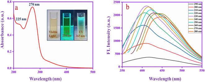
Fig. 1a shows the UV absorbance spectrum of CQDs. The spectrum has two absorption bands at 225 nm, which corresponds to the aromatic sp2 π–π* transition of the graphitic core (C–C and CC) and 270 nm can be assigned to the n–π* transitions for the carbonyl group (CO) that confirms the carbonyl functional group located in the CQD surface.49 The inset images represent the emission behaviour of CQDs at different excitations. Moreover, to evaluate the fluorescence properties of CQDs in detail, the excitation wavelength was altered from 290 to 380 nm, as shown in Fig. 1b. A red shift occurs in different excitation wavelengths and reaches high intensity at 330 nm and then decreases. The redshift behaviour may be due to the π → π* transition of the graphitic sp2 core at lower excitation energies. The shift indicates several emission trap states, and various size dots are presented in the CQD.50 The result indicates that the CQD has superior absorbance and emission properties.
 |
| | Fig. 1 (a) UV spectrum and (b) different excitation fluorescence study of CQDs (290–380 nm). | |
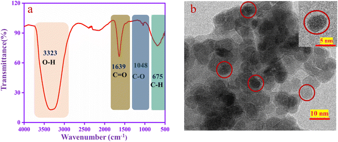
The functional groups are confirmed by FT-IR spectroscopy, as shown in Fig. 2a. A U-shaped peak at 3323 cm−1 corresponds to the –OH functional group. The peak at 1639 cm−1 is assigned to the stretching frequency of CO and that at 1048 cm−1 to the stretching frequency of C–O.51 The aromatic C–H peaks appear at 675 cm−1. From the results, this is confirmed that the functional groups such as –OH, CO and C–O are present in the CQD. The TEM image (Fig. 2b) revealed that the CQD has a spherical shape with a diameter is 2–10 nm, which is well dispersed in the solution.52
 |
| | Fig. 2 (a) FT-IR spectra and (b) TEM image of CQDs. | |
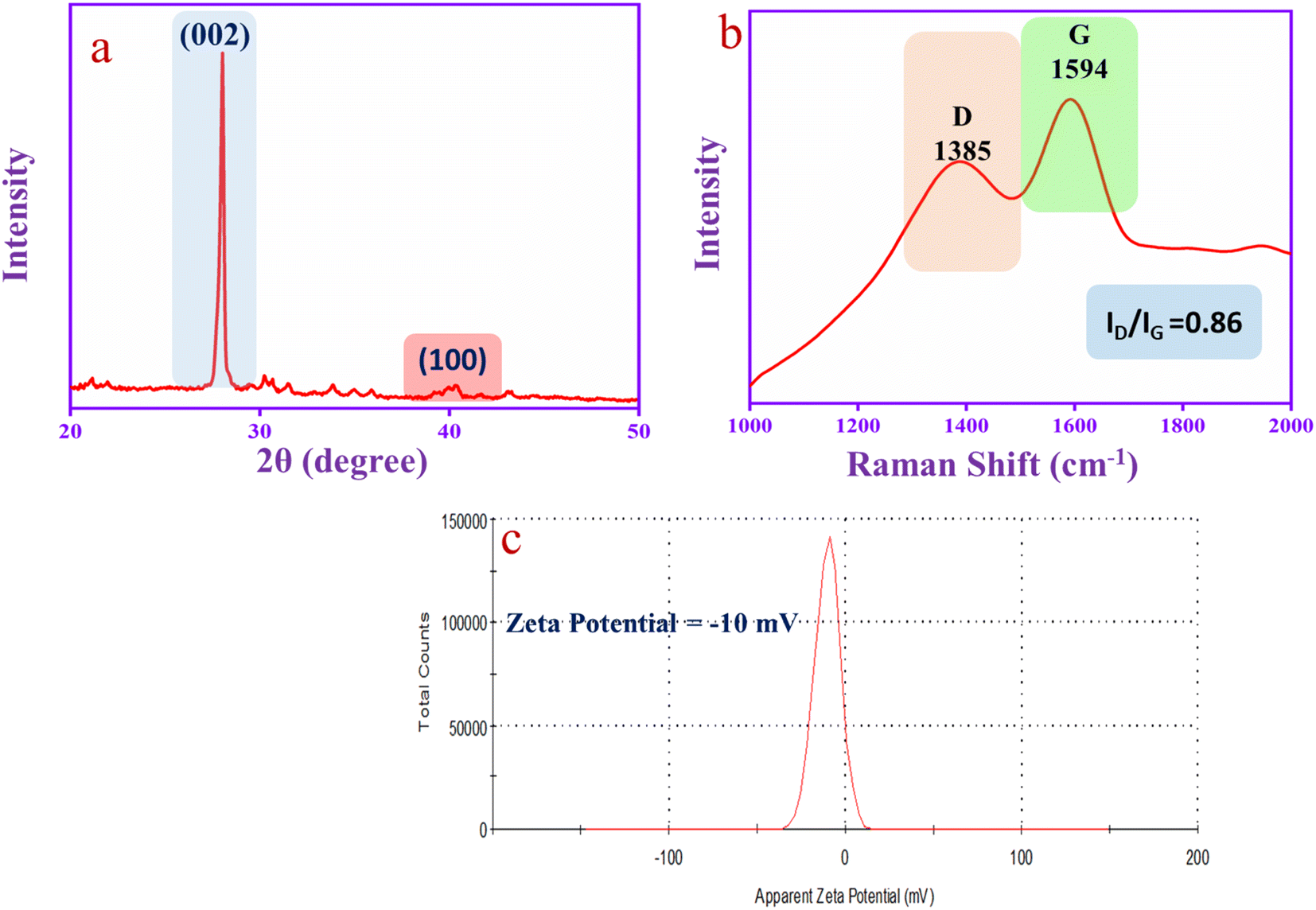
The XRD spectrum of CQD is shown in Fig. 3a. The spectrum has two diffraction peaks at 2θ = 28° (sharp peak) and 2θ = 40° (flat peak) that correspond to the graphitic carbon diffraction patterns (002) and (100), respectively.53 The Raman spectrum in Fig. 3b has been used to investigate the structure of the CQD that exhibits two predominate broad peaks at 1385 cm−1 and 1594 cm−1, corresponding to the D-band (defects and disorder of sp2 graphene lattice structures) and G-band (sp2 hybridized graphene lattice structures), respectively. The G-band is recognized as the graphitic carbon E2g vibrational mode correlated with the sp2 hybridized carbon atom vibration. The result suggests that the CQD has an aromatic character. The ID/IG ratio of the CQD is 0.86, which indicates the graphic core in the CQD structure.54 Moreover, the CQD was exposed to zeta potential analysis. The CQD has oxygenated functional groups such as –OH, –COOH and CO that show a negative value of zeta potential (−10 mV), as shown in Fig. 3c. The hydroxyl group of the CQD can easily donate protons and make the negative charge on the CQD surface as the zeta potential value is negative.55
 |
| | Fig. 3 (a) XRD, (b) Raman spectra and (c) zeta potential of CQDs. | |
Electrochemical polymerization of polyaniline–carbon quantum dot-copper on carbon cloth
Polyaniline (PANI) electropolymerization involves four steps: (1) monomer oxidation and primary cation formation in the anode, (2) rearomatization, deprotonation, and dimer formation, (3) chain formation – oxidation of a monomer to a cation radical, and (4) spontaneous doping to produce a doped polymeric chain.56,57 The chain has two repeating units: a quinoid ring (oxidized form) and a benzene ring (reduced form). The various polymer composite electrochemical coating forms are depicted in Fig. 4a–d graphs. The appropriate electrolyte mixture for the polymerization process is represented (inset digital images).
 |
| | Fig. 4 Electrochemical polymerization of (a) PANI, (b) PANI-CQD, (c) PANI-Cu and (d) PANI-CQD-Cu. | |
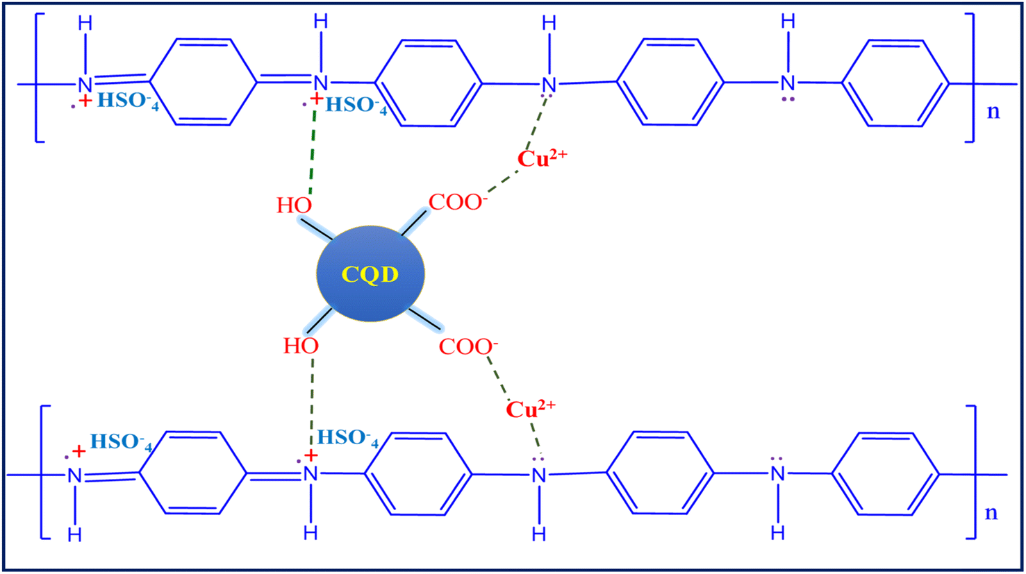
The aniline monomer electrolyte was transparent (Fig. 4a), the aniline–carbon quantum dot (CQD) monomer electrolyte was brown in colour (Fig. 4b), and the aniline–copper monomer electrolyte was blue in colour (Fig. 4c). Noteworthy, the aniline-CQD-Cu monomer composite electrolyte solution was green in colour (Fig. 4d), because of the formation of a coordination complex of aniline with CQDs (ligand) and copper (Cu-metal). In the electropolymerization process, in the first scan, no considerable oxidation and reduction occurred because, initially, the electrode started interacting with the monomer solution. In the second scan, aniline involves a polymerization process that exhibits four types of peaks, two peaks were presented in the oxidation region. The first peak denoted the conversion of leucoemeraldine to emeraldine salt and the second denoted emeraldine salt-to-pernigraniline state conversion. In the reduction region, pernigraniline is converted into an emeraldine base, and then, it is converted into leucoemeraldine.58 This was a cyclic process that was repeated five times, and finally, the PANI (amine–imine) was formed. The photograph and SEM image of carbon cloth and PANI-CQD-Cu-coated carbon cloth are depicted in Scheme S1.† In PANI-CQD-Cu, the CQD negative charged functional groups interact with PANI amine functional groups (positive) and Cu (positive), forming a composite (PANI-CQD-Cu) during the electropolymerization process, as shown in Scheme 1.
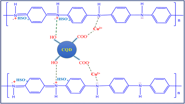 |
| | Scheme 1 Schematic illustration of the interaction of PANI, CQDs and Cu. | |
X-ray diffraction and Raman analysis
X-ray diffraction (XRD) analysis was performed to study the interaction of PANI with CQDs and Cu metal, and the results are shown in Fig. 5a. The carbon cloth (CC) diffraction peak appeared at 2θ = 25.18° and 42.98°, assigned to the (002) (101) planes of the graphite. The PANI diffraction peaks coincide with the CC diffraction peaks and appeared at 24.88° and 42.36° with d-spacing values of 3.57 and 2.13 Å corresponding to the perpendicular and parallel periodicity arrangement of the PANI chain.46 The broad and low-intense peak indicates the low crystalline nature of PANI. The peak corresponds to the repetition of benzenoid and quinoid units in the polymer chain.59 The PANI-CQD and PANI-Cu diffraction peaks slightly shifted the position and located at 24.98°, 42.56° and 25.34°, 41.72° due to the interaction of the PANI chain with CQD and Cu. Moreover, PANI-CQD-Cu in the range of 24° was split60 into two peaks at 24.10° and 25.23°.61 The d-spacing value also increased to 3.69 and 3.52 Å. There was no Cu peak presented, which indicates that a low level of Cu is present in the PANI matrix. The result indicates that no crystalline order has been added to the composite.62 The low level of Cu was inter-growth on the polymer chain (PANI) that creates different tunnel structures in the composite that could improve cation diffusion.63 Subsequently, the composite can provide more capacitance and cycling stability during the charge–discharge process.
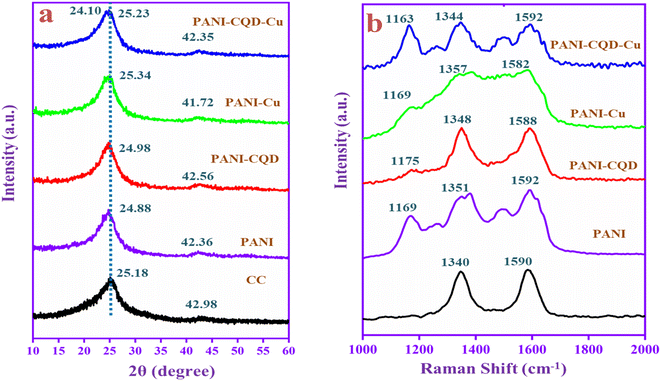 |
| | Fig. 5 (a) XRD patterns and (b) Raman spectra of CC, PANI, PANI-CQD, PANI-Cu and PANI-CQD-Cu electrode materials. | |
Fig. 5b depicts the Raman spectra of the prepared electrode materials. Raman spectroscopy is a powerful technique to identify the disorder crystal structure of carbon materials and polymers. The CC has two peaks that appeared at 1340 (D band) and 1590 cm−1 (G band). The D band represents the breathing mode of A1g and the G band corresponds to the in-plane bond-stretching mode of Eg (sp2).64 In PANI, the three peaks given at 1169, 1351 and 1592 cm−1 correspond to the characteristic peak of C–H bending of the quinoid ring, C–N+ stretching of bipolaron (delocalized polaronic ring) and N–H bending of benzenoid in the PANI chain. The PANI Raman spectra peaks demonstrate PANI coated on CC in emeraldine salt state, which is good conductive. The conductive PANI network's direct growth on the CC porous framework can provide sufficient active surface area and accelerate the faradaic reaction with efficient charge transport along the nanofiber direction that behaviour boosts the electrochemical performance for the energy storage application. The PANI-CQD composite also has the same range of peaks, but they have slightly shifted the position and the peaks were sharp.65 For instance, the PANI-CQD quinoid ring C–N+ peak shifted towards a lower wavenumber that was 1348 cm−1 owing to their π–π* electron interaction between the CQD carbon network (D and G bands) and the PANI quinoid ring. Such interaction can provide good interfacial adhesion between PANI and CQDs and enhance electron transportation during redox reactions.66,67 The interaction can enhance electron transportation during the electrochemical redox reaction process.68 Compared to PANI-CQD, the PANI-CQD-Cu composite C–H (1163 cm−1) and C–N+ (1344 cm−1) stretching frequencies were red-shifted (lower wavenumber), which confirms PANI's (C–N) interaction with the CQD functional group (OH) and the Cu2+ ions via the electrostatic π–π* interaction. In this process, the CQD and Cu can bind to the PANI chain via covalent or hydrogen bond interactions that effectively restrain the movement of the PANI chain. Hence, the stretching frequencies were red-shifted.69
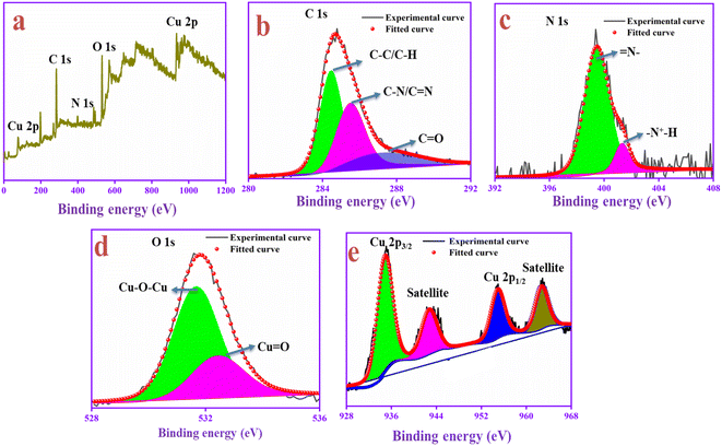
X-ray photoelectron spectroscopy analysis
The chemical composition and surface structure of the PANI-CQD-Cu electrode material were confirmed by XPS analysis. This XPS survey spectrum contains carbon, nitrogen, oxygen and copper elements, and is shown in Fig. 6a. In the C 1s spectrum (Fig. 6b), the peak appears at 284.54 eV corresponding to the sp2 hybridized (C–C/C–H) PANI aromatic carbon and CQD carbon skeleton, the peak 285.51 eV represents the imine group of the PANI (C–N)70 and the peak 287.14 eV denotes the carbonyl group (CO) of CQDs. In Fig. 6c, the N 1s spectrum was deconvoluted into two peaks 399.81 and 401.11 eV assigned to the benzenoid amine (N–) and quinoid imine (N+H–) functional group of PANI, which confirms that the positive nitrogen species are present in the polymer chain. The benzenoid amine (N–) lone pairs can bind to the Cu ions via a covalent bond. The bond can induce pseudo-capacitance and improve electron transfer during the charge–discharge process. Moreover, the (N+H–) positive nature in the PANI backbone with SO42−, which was from the electrolyte, can easily bind to the negative rich CQD functional groups and improve the conductive nature during the redox process.71,72 The analysis was consistent with Raman's result. The O 1s spectrum (Fig. 6d) binding energies are presented at 531.65 and 532.86 eV, which represents the bond formation of Cu with the oxygen atom of the CQD in the form of Cu–O–Cu and CuO. In the Cu core level spectrum depicted in Fig. 6e, Cu in the oxide form gave two peaks at 935.80 eV for Cu 2p3/2 and 954.75 eV for Cu 2p1/2.73 The binding energy gap was 18.95 eV, which confirmed that copper was present in the PANI-CQD-Cu composite.74 For supercapacitor applications, the metal and polymer interaction was a crucial parameter for electron transfer kinetics. The result suggests that the Cu ions are bound in the PANI composite, which suggests that it can deliver a higher capacitance during the electrochemical reaction.
 |
| | Fig. 6 XPS spectrum of the prepared electrode material of PANI-CQD-Cu: (a) survey spectra, (b) C 1s spectra, (c) N 1s spectra, (d) O 1s spectra and (e) Cu 2p spectra. | |
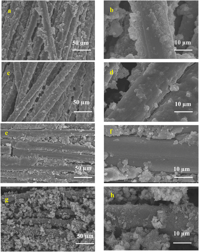
Investigation of surface morphology and elemental analysis of the composite electrode materials by SEM
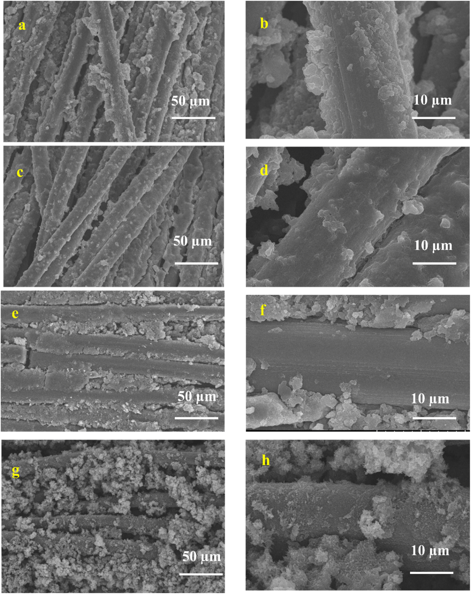
It is well known that carbon cloth (CC) is a microstructure of compact bundle fibers that have uniform smooth surfaces. PANI (Fig. 7a and b) was directly aligned on the surface of the CC, which was smooth with a 3D coral-like morphology.75 The binder-free interaction of PANI and CC is crucial for rapid electron transfer in the electrochemical cell, resulting in the charge storage capability being improved.76 In PANI-CQDs (Fig. 7c and d), PANI was uniformly spread in CC fibers due to the binding interaction of PANI (N+H) with the hydroxyl group of CQDs. This result suggests that the CQD acts as a surfactant for improving polymer growth in the polymerization process.65 The PANI-Cu (Fig. 7e and f) electrode material has a high level of polymer growth that was strictly accumulated between the CC fibers and PANI and Cu. Interestingly, PANI-CQD-Cu (Fig. 7g and h) has a uniform growth morphology and a sphere-like structure,77 and CC was fully covered by the polymer owing to the surfactant behaviour of CQDs and the interaction between PANI and Cu. This surface morphology improves the electrolyte ion insertion and diffusion process to the boundary in the electrochemical cells.60 Moreover, the uniform distribution of PANI on the CC substrate is an ideal candidate for energy storage devices since it has more active sites for ions and charge transfer processes in faradaic reactions. In addition, the reasonable binder-free interaction between PANI-CQD-Cu and CC is one of the benefits of rapid electron transfer, resulting in the improvement of charge storage and deliver capacity.76
 |
| | Fig. 7 SEM images of (a and b) PANI, (c and d), PANI-CQD, (e and f) PANI-Cu and (g and h) PANI-CQD-Cu. | |
The elemental compositions of PANI, PANI-CQD, PANI-Cu and PANI-CQD-Cu were confirmed by energy-dispersive X-ray (EDAX) analysis. The spectrum (Fig. S1a†) for PANI revealed the presence of the elements carbon (55.06%), oxygen (27.25%) and nitrogen (17.69%). Meanwhile, the PANI-CQD (Fig. S1b†) has a higher level of carbon content (88.19%) due to the presence of large amounts of carbon present in the CQD. Other elements such as oxygen (6.81%) and nitrogen (4.51%) are also present in the PANI-CQD. The additional peak sulphur (4.90%) may be the impurities of the composite that come from H2SO4 which is used as a supportive solvent for electro-polymerization. The PANI-Cu spectra consist of carbon (27.67%), oxygen (47.36%), nitrogen (05.80%) and copper (19.16%), as shown in Fig. S1c.† The copper and oxygen elements confirm that copper oxide is present in PANI-Cu. The PANI-CQD-Cu EDAX spectrum (Fig. S1d†) has four types of elements, namely, carbon (58.85%), oxygen (06.00%) nitrogen (15.87%) and copper (19.28%). Compared to PANI-Cu, PANI-CQD-Cu has a higher amount of carbon, which confirms that CQDs are present in the composite.
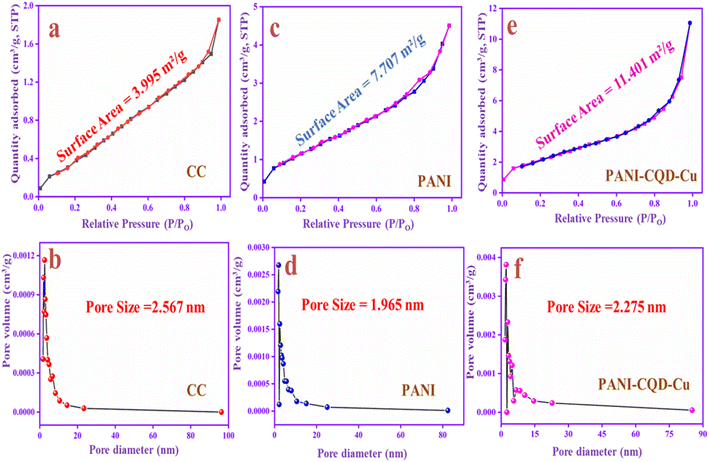
Brunauer–Emmett–Teller analysis
The specific surface area and pore size distributions of CC, PANI and PANI-CQD-Cu were investigated by N2 adsorption–desorption measurements with the Brunauer–Emmett–Teller (BET) analysis and Barrett–Joyner–Halenda (BJH) methods. The BET surface area of the CC is 3.995 m2 g−1, PANI is 7.707 m2 g−1 and PANI-CQD-Cu is 11.401 m2 g−1, which are shown in Fig. 8a, c and e, respectively. The specific surface area of PANI-CQD-Cu is nearly 2 times higher than that of CC and 1 time higher than that of PANI. The surface area improvement may be attributed to the interaction of PANI with the CQD and the copper ions during the electropolymerization process.78 Moreover, the pore volume of the PANI-CQD-Cu is 0.019 cc g−1, which is also higher than that of CC (0.004 cc g−1) and that of PANI (0.009 cc g−1). The pore size of CC is 2.56 nm, while that of PANI and PANI-CQD-Cu decreased, which are 1.96 and 2.27 nm. According to the obtained data, PANI-CQD-Cu has a higher surface area and porous volume with a moderate pore size nature that can provide more electro-active sites on the electrode surface and promote rapid ion transportation with the shorter diffusion paths in the electrochemical reaction.79
 |
| | Fig. 8 N2 adsorption isotherms and pore size distributions of CC (a and b), PANI (c and d) and PANI-CQD-Cu (e and f). | |
Electrochemical analysis of supercapacitors: a three-electrode system
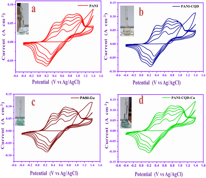
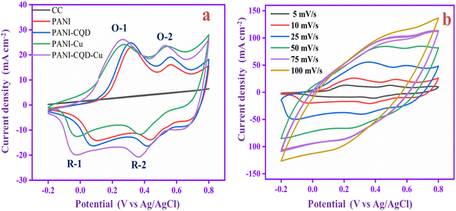
The electrochemical analysis of the PANI, PANI-CQD, PANI-Cu, and PANI-CQD-Cu electrode materials was performed by cyclic voltammetry (CV) with a 1 M H2SO4 electrolyte solution at a scan rate of 10 mV s−1 (Fig. 9a). The CV curve of CC has no pair of redox peaks (rectangular shape), exhibiting the double-layer capacitance characteristics, whereas PANI has two sets of redox couples based on the transformation states, which is depicted in Fig. 9a. The first redox peak appeared between 0.32 and 0.1 V (O-1 and R-1) versus Ag/AgCl as the reference electrode corresponding to the conversion of a fully reduced leucoemeraldine base state to the partially oxidized emeraldine state. The second redox peak was presented between 0.56 and 0.42 V (O-2 and R-2) to the conversion of emeraldine to the fully oxidized form of pernigraniline.67 The PANI-CQD peaks were also presented at the same voltage, but the CV integrated curve and current density were slightly increased. The curve and conductivity enhancement confirm that the CQD enhanced the capacitance behaviour of PANI.80 The voltage redox peaks (O-2 and R-2) of PANI-Cu and PANI-CQD-Cu shifted their position, and the range was 0.53 & 0.36 V and 0.52 & 0.35 V, respectively. Moreover, the current range of PANI-Cu and PANI-CQD-Cu increased owing to the bond formation of Cu with the polymer chain. PANI-CQD-Cu has a higher CV curve area and current range among the other electrodes. It is well known that the CV curve area is proportional to the specific capacitance of the electrode. Therefore, the result indicates that PANI-CQD-Cu is a promising electrode material for supercapacitor applications. In Fig. 9b, PANI-CQD-Cu involved a scan rate study, and the CV area curves increased when the scan rate was increased.81 The shape of CV curves and the peak height were enhanced and the oxidation–reduction peak potential was shifted from 5 to 100 mV s−1. The oxidation peaks are positively shifted and the reduction peaks are negatively shifted and changes are attributed to the resistance of the electrode.82 The current response gradually increased, exhibiting the excellent rate capability of the PANI-CQD-Cu electrode.
 |
| | Fig. 9 (a) CV of CC, PANI, PANI-CQD, PANI-Cu and PANI-CQD-Cu electrode materials. (b) Scan rate study of the PANI-CQD-Cu electrode material. | |
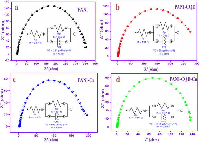
Electrochemical impedance spectroscopy (EIS) is a great tool to gain a fundamental understanding of the electrochemical reactions at the electrode–electrolyte interface. The Nyquist plots of polymer electrodes are in the frequency range of 0.01 Hz–100 kHz with an open-circuit potential voltage. The impedance spectra of PANI, PANI-CQD, PANI-Cu and PANI-CQD-Cu have a semi-circle produced by the parallel combination of resistance and capacitance in the high-frequency region.83 Moreover, the diameter of the circle indicates the resistance at the electrode and electrolyte interface, which forms a charge-transfer resistance (Rp). Among these electrodes, the PANI-CQD-Cu electrode holds a small diameter semi-circle that suggests the higher ionic conductivity of the electrode. The result reveals that the charge transmission rate between the electrode and the electrolyte was more significant, and the property was responsible for high charge storage capability.84 To gain more information about the resistance behaviour, the PANI, PANI-CQD, PANI-Cu and PANI-CQD-Cu impedance spectra involved an electrochemical fitting process, as shown in Fig. 10a–d. The fitting process provides the equivalent circuits that consist of solution resistance (Rs), electronic charge transfer resistance (Rp) and constant phase element (CPE).85 The Rs value was determined for the following electrodes: PANI (3.67 Ω), PANI-CQD (1.91 Ω), PANI-Cu (2.28 Ω) and PANI-CQD-Cu (1.46 Ω). The Rp values was PANI (350 Ω), coulomb efficiency PANI-CQD (282 Ω), PANI-Cu (199 Ω) and PANI-CQD-Cu (137 Ω). Compared to other electrodes, PANI-CQD-Cu (Fig. 10d) has lower Rs and Rp values, which was a crucial factor for energy storage devices because low resistance can enhance the rapid redox reaction. Moreover, the appearance of CPE may be the reason for the porosity of the electrode.86 The CPE is defined using eqn (1):
where
w is the angular frequency, and
TCPE and
n are frequency-independent constants. It is well known that
n is a correction factor related to the electrode roughness. The values
n = 0 to 1 denote the CPE as an ideal capacitor, whereas
n = 0 to 0.5 denotes a Warburg behavior. The PANI-CQD-Cu ‘
n’ value was 0.91, which demonstrates that the electrode has ideal supercapacitor behaviour (pseudo capacitance). PANI-CQD-Cu exhibits lower
Rs and
Rp, indicating that the combination of PANI, CQD and Cu enhances the electrical conductivity of the electrode material. The results are consistent with the CV study.
 |
| | Fig. 10 EIS spectra and the equivalent circuits of (a) PANI, (b) PANI-CQD, (c) PANI-Cu and (d) PANI-CQD-Cu. | |
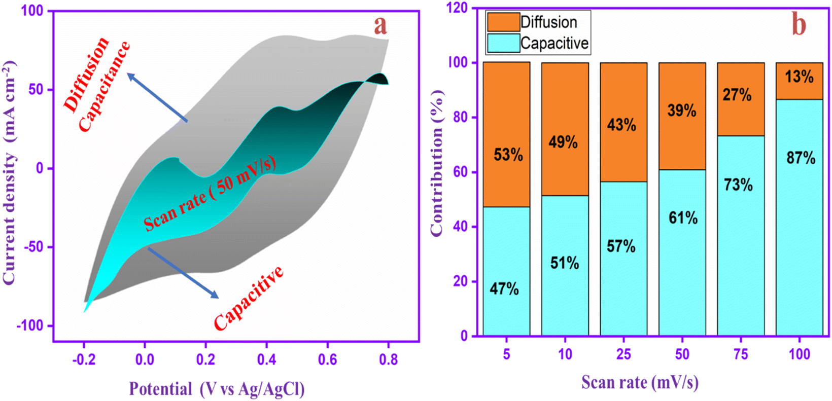
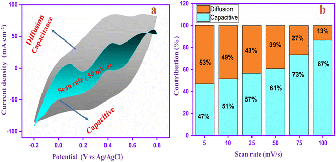
To identify the capacitance ratio of the PANI-CQD-Cu electrode, the diffusion and surface control process of the electrode was evaluated at a scan rate of 5–100 mV s−1. According to the energy distribution of the electrode material, the PANI-CQD-Cu electrode's total amount of charge storage was separated into two types: surface capacitance and diffusion capacitance. Moreover, the surface capacitance was constructed in two parts: (i) electric double layer capacitance (EDLC) and (ii) pseudocapacitance. Based on the Dunn group and co-worker reports, the capacitive effects can be described using eqn (2) based on the scan rate study:
where
Ip is the current (A) corresponding to the redox peaks,
v is the scan rate (mV s
−1),
k1 and
k2 are constant coefficients,
k1v is the current from the surface capacitance, and
k2v0.5 is the process of the diffusion-controlled intercalation.
Fig. 11a displays the proportion of diffusion capacitance and capacitive (shaded region) for charge storage contributions at 50 mV s−1. It clearly shows that the contribution rate of surface capacitance was 61%, whereas the diffusion capacitance was 39%. Moreover, the contribution rates of the PANI-CQD-Cu electrode in different scan rates are shown in Fig. 11b. At a low scan rate of 5 mV s−1, the capacitive contribution was lower (47%) than the diffusion contribution (53%). When the scan rate speed was increased, the capacitive contribution (surface capacitance) was gradually enhanced, reaching 87% at 100 mV s−1. The PANI-CQD-Cu electrode has a large capacitive contribution owing to their fast ion/electron migration at the electrode/electrolyte interface, which was a significant property for achieving excellent cyclic performance and rate capability at high current density.87
 |
| | Fig. 11 (a) Proportion of capacitive and diffusion capacitance for charge storage contributions of the PANI-CQD-Cu electrode at 50 mV s−1 and (b) comparison of the stored charge at scan rates of 5, 10, 25, 50, 75 and 100 mV s−1. | |
In Fig. 12a, the capacitance behavior of PANI, PANI-CQD, PANI-Cu, and PANI-CQD-Cu electrode materials was evaluated by the galvanostatic charge–discharge (GCD) test, in the potential window from −0.2 to 0.8 V. The specific capacitance was calculated using eqn (3):88
where
C is the specific capacitance,
I is the discharge current, Δ
t is the discharge time, Δ
V is the voltage difference and
m is the mass of active material. According to
eqn (3), the specific capacitance value of PANI-CQD-Cu was 1070 mF cm
−2 at a current density of 5 mA cm
−2 (1070 F g
−1 at 1 A g
−1), whereas for PANI, PANI-CQD and PANI-Cu, the specific capacitance values were 775, 875, and 930 mF cm
−2, respectively. Among these, the PANI-CQD-Cu electrode gives a higher capacitance, in which the polymer stores more electric charge by a redox reaction with the help of CQD and Cu. This was a combined energy storage mechanism of EDLC and pseudo-capacitance.
81 The fast charge transport of carbon and electron transport of metal helps to improve the electrochemical behaviour of PANI. For this reason, the PANI-CQD-Cu electrode material has excellent capacitive performance than other electrode materials.
Fig. 12b shows the GCD study of PANI-CQD-Cu at different current densities (5, 10, 15, 20 and 25 mA cm
−2). The electrode capacitance value was that all GCD curves were symmetrical, which indicates that the material has good redox reversibility and stability. The relationship between the capacitance and current density of different electrodes is shown in
Fig. 12c. The current density increases from 5 to 25 mA cm
−2, and the specific capacitance values of PANI, PANI-CQD, PANI-Cu and PANI-CQD-Cu decrease gradually, for instance, the specific capacitance values of the PANI and PANI-CQD-Cu electrodes were 775 to 625 and 1070 to 800 mF cm
−2, respectively. The capacitance loss during the charge–discharge process is unsurprising. It is well known that the high current density needs rapid charge or electron migration to the electrode surface and electrolyte.
89 In PANI-CQD-Cu, the CQD and Cu metals bind with PANI allowing us to speed up the charge migration and enhance the energy storage capability at high current densities. The electrochemical charge–discharge cyclic stability of PANI-CQD-Cu was investigated by GCD at 25 mA cm
−2, as shown in
Fig. 12d (see circular point). The capacitance value of the PANI-CQD-Cu electrode material was gradually decreased during the repeating cyclic processes. After 1000 cycles, the cyclic stability of 93% was retained, which indicated the good cyclic stability of the prepared electrode material. Moreover, the coulombic efficiency (the ratio of charge and discharge capacitance) of the PANI-CQD-Cu electrode during the cycling process (see diamond point), exhibits 95.45% based on
eqn (4):
where
tD is the discharging time and
tC is the charging time, based on the result. The PANI-CQD-Cu electrode has a stable coulombic efficiency over 1000 cycles, so it was a suitable material for supercapacitor applications.
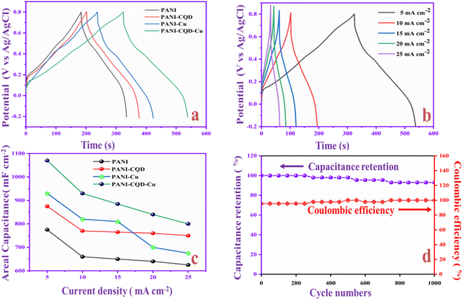 |
| | Fig. 12 (a) GCD study of polymer electrodes. (b) Different current density study of the PANI-CQD-Cu electrode material. (c) Specific capacitance of polymer electrodes at different current densities. (d) Cycling stability and coulombic efficiency studies of the PANI-CQD-Cu electrode (circular point: capacitance retention; diamond point: coulombic efficiency). | |
The electrochemical performances of PANI-CQD-Cu in comparison with the reported PANI-CQD and PANI-Cu-based materials are listed in Table 2. It was evident that the PANI-CQD-Cu electrode has a higher capacitance than that reported in previous works. The result indicated that PANI-CQD-Cu is a suitable material for supercapacitor applications.
Table 2 Electrochemical performances of PANI-CQD-Cu in comparison with the reported PANI-CQD and PANI-Cu-based materials
| S. No. |
PANI based composite |
Preparation method |
Potential window (V) |
Electrolyte |
Current density |
Capacitance |
Ref. |
| 1 |
CQD/PANI |
Electrochemical polymerization |
0–0.6 V |
1 M H2SO4 |
1 A g−1 |
738.3 F g−1 |
67
|
| 2 |
PANI/C-dots |
Chemical polymerization |
−0.4–0.8 V |
1 M NaCl |
1 A g−1 |
529 F g−1 |
90
|
| 3 |
CDs-PMo12-PANI |
Electrochemical polymerization |
0–0.7 V |
1 M H2SO4 |
1 A g−1 |
479 F g−1 |
91
|
| 4 |
CQD@PANI |
Chemical polymerization |
0–0.6 V |
1 M H2SO4 |
1 A g−1 |
222 F g−1 |
92
|
| 5 |
PANI-N, S-GQDs@CeO2 |
Chemical polymerization |
0–0.8 V |
1 M H2SO4 |
1 A g−1 |
189 C g−1 |
93
|
| 6 |
N-CQD/PANI |
Chemical polymerization |
−0.2–0.8 V |
1 M H2SO4 |
1 A g−1 |
498 F g−1 |
94
|
| 7 |
PANI/ZnS QD |
Chemical polymerization |
0–1.2 V |
1 M H2SO4 |
1 A g−1 |
893 F g−1 |
95
|
| 8 |
PANI-Cu2+ |
Electrochemical polymerization |
0–0.7 V |
0.5 M H2SO4 |
6 mA cm−2 |
618 F g−1 |
46
|
| 9 |
CuO@PANi NFs |
Chemical polymerization |
0–1 V |
1 M H2SO4 |
0.5 mA cm−2 |
169 F cm−2 |
96
|
| 10 |
rGO-copper oxide-PANI |
Chemical polymerization |
0–0.7 V |
2 M Na2SO4 |
0.25 A g−1 |
213 F g−1 |
97
|
| 11 |
PANI-CQD-Cu |
Electrochemical polymerization |
−0.2–0.8 V |
1 M H2SO4 |
5 mA cm−2 or 1 A g−1 |
1070 mF cm−2 or 1070 F g−1 |
This work |
Electrochemical analysis of the flexible asymmetry supercapacitor (FASC) device
Flexible solid-state supercapacitors have attracted considerable attention compared with liquid-state supercapacitors because they possess superior electrical and mechanical properties and preferable electrochemical activity.83 Therefore, we constructed the flexible asymmetry supercapacitor (FASC) device (activated carbon (AC)/PVA-H2SO4/PANI-CQD-Cu), in which AC was the negative electrode, PVA–H2SO4 was the solid electrolyte and PANI-CQD-Cu was the positive electrode.67 The negative and positive electrode potential windows were analyzed using a three-electrode system; the potential window was from −1 to 0.8 V (Fig. 13a). The different potential window-based CV study (from 0–0.8 V to 0–1.8 V) at 50 mV s−1 was evaluated, and the results are shown in Fig. 13b. The current range and area of the CV curves are gradually increased up to 1.6 V, which provide the feasibility of this voltage for the device. Meanwhile, it is noted that when the potential reached 1.8 V, the CV curves give a sharp peak due to the oxygen emergence. From the results, the device suitable window range is optimized, which is 0–1.6 V. The FASC device CV curve oxidation and reduction peaks are almost the same at a voltage of 1.6 V, which indicates the superior capacitance behavior of the fabricated device. Different scan rates (10–100 mV s−1) at 0–1.6 V were studied (Fig. 13c). Basically, the PANI redox form changed to a rectangular shape, when the scan rate was increased. Remarkably, the redox process has no change up to 100 mV s−1 in our (AC/PVA-H2SO4/PANI-CQD-Cu) device, which is due to the electrostatic interaction of Cu with PANI. In order to prove the superior mechanical flexibility of the device, the device involves the CV study in the flat (original) state and bend state at 50 mV s−1. In Fig. 13d, the flat and bending angles of the device show no obvious shape change in the CV curve, which indicates that the AC/PVA-H2SO4/PANI-CQD-Cu device has excellent mechanical property and flexibility.
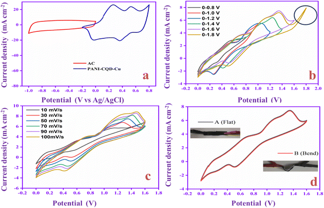 |
| | Fig. 13 (a) CV study of AC and PANI-CQD-Cu in a three-electrode system. Electrochemical performance: (b) CV curves in different potential windows, (c) scan rate study and (d) bending performance of the AC/PVA-H2SO4/PANI-CQD-Cu device. | |
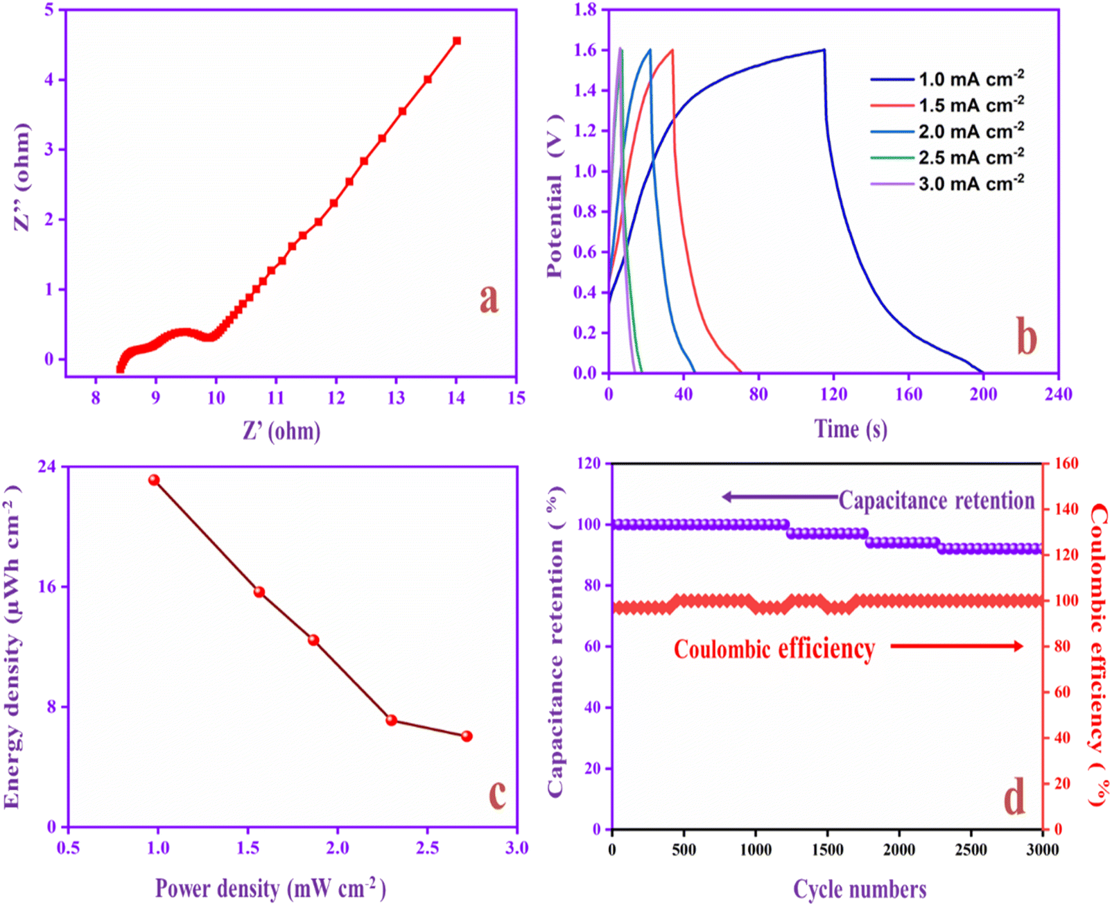
The ion transport property and electrochemical behavior of the device were evaluated by EIS measurement. In Fig. 14a, the Nyquist plot of the device exhibits the solution resistance (Rs) and charge resistance (Rct) appearing at 8.3 Ω and 1.6 Ω. The resistance value is low, confirming the good electrically conductive behaviour of the AC/PVA-H2SO4/PANI-CQD-Cu device. In addition, the low region of the EIS graph has a vertical line that denotes the ideal capacitive and ion diffusion behavior of the electrode material.93Fig. 14b shows the accurate capacitance performance of the device studied by GCD measurements at different current densities ranging from 1 to 3 mA cm−2. The specific capacitance was calculated based on eqn (3).
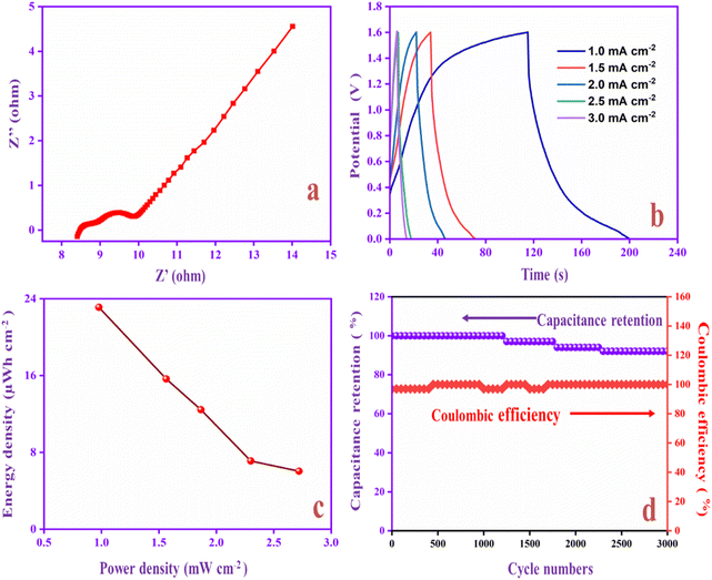 |
| | Fig. 14 (a) EIS study, (b) GCD, (c) Ragone plot and (d) cycling stability and coulombic efficiency of the AC/PVA-H2SO4/PANI-CQD-Cu device (circular point: capacitance retention; diamond point: coulombic efficiency). | |
The specific areal capacitance of the device was 65 mF cm−2 at 1 mA cm−2. The areal capacitance was gradually decreased based on the current density improvement, confirming the good rate capability of the device. The Ragone plot of the device represents the energy and power density of PANI-CQD-Cu, as shown in Fig. 14c. Eqn (5) for energy (μW h cm−2) and eqn (6) for power density (mW cm−2):
where
E is the energy density,
P is the power density,
C is the specific areal capacitance, Δ
t is the discharging time and Δ
t is the voltage. The device delivers 23.10 μW h cm
−2 energy and 0.978 mW cm
−2 power density at a current density of 1 mA cm
−2. The above-mentioned energy value is comparable to or higher than that of the previously reported PANI-based flexible supercapacitors (FSCs) such as PANI-Mxene-based FSCs (22.10 μW h cm
−2),
98 PANI-carbon nanofiber (CNF) nanowire FSCs (21.40 μW h cm
−2),
99 PANI-graphene composite FSCs (17.10 μW h cm
−2),
100 PANI-graphene fiber FSCs (12.19 μW h cm
−2)
101 and PANI-graphene fiber nanosheet FSCs (21.0 μW h cm
−2).
102 The Ragone comparison graph is depicted in Fig. S2.
† The above-mentioned result indicated that the AC/PVA-H
2SO
4/PANI-CQD-Cu device has excellent energy and power density and significant potential for commercial applications. Moreover, the cycling performance of the asymmetry device was studied at 3 mA cm
−2. The device exhibits a capacitance retention of 92% after 3000 galvanostatic cycles, as shown in
Fig. 14d. Furthermore, the coulombic efficiency value was 97%, and the result indicates that the AC/PVA-H
2SO
4/PANI-CQD-Cu device has rapid-electron transfer behavior for charge storage and delivery, so that it was a potential material for supercapacitor applications.
Conclusions
A flexible PANI-CQD-Cu electrode has been prepared by an electrochemical polymerization method. CQDs acted as the surfactant that improves the growth and tunes the morphological structure of PANI. PANI-CQD-Cu is used as a flexible electrode material in the SC studies, and the capacitance value was 1070 mF cm−2 at 5 mA cm−2 that exceeds that of most of the reported PANI-CQD and PANI-Cu-based supercapacitors. The charge storage processes based on diffusion (13%) and capacitive control behaviour (87%) were investigated. Moreover, the AC/PVA-H2SO4/PANI-CQD-Cu flexible device delivers superior energy (23.10 μW h cm−2) and power density (0.978 mW cm−2). Noteworthy, the device gives excellent cycling stability (92% capacitance retention) after 3000 charge/discharge cycles with 97% coulombic efficiency. Based on the findings, the CQD and Cu improve the conductive and capacitance range of PANI on the CC substrate. Therefore, the electrochemical preparation of the flexible PANI-CQD-Cu electrode is an easier route to produce wearable supercapacitors that inspire promoting future flexible power supplies.
Conflicts of interest
There is no conflict of interest reported in this presentation.
Acknowledgements
Na'il Saleh acknowledges the financial support by United Arab Emirates University (Grant # 12S106).
References
- Y. Zhou, H. Qi, J. Yang, Z. Bo, F. Huang, M. S. Islam, X. Lu, L. Dai, R. Amal, C. H. Wang and Z. Han, Energy Environ. Sci., 2021, 14, 1854–1896 RSC.
- P. Dhandapani, A. Udayakumar, S. P. Rajendra, M. S. AlSalhi, J. Z. Guo and S. Angaiah, Sustainable Energy Fuels, 2023, 7, 2368 RSC.
- P. Dhandapani, B. Balan, T. Dinadayalane and S. Angaiah, J. Energy Storage, 2022, 56, 105943 CrossRef.
- M. Sandhiya, Vivekanand, S. S. Balaji and M. Sathish, ACS Appl. Energy Mater., 2020, 3(11), 11368–11377 CrossRef CAS.
- Y. Wang, X. Wu, Y. Han and T. Li, J. Energy Storage, 2021, 42, 103053 CrossRef.
- X. Zou, D. Wu, Y. Mu, L. Xing, W. Zhang, Z. Gao, F. Xu and K. Jiang, Carbon, 2020, 159, 94–101 CrossRef CAS.
- Y. Wang, S. Tang, S. Vongehr, J. Ali Syed, X. Wang and X. Meng, Sci. Rep., 2016, 6, 12883 CrossRef CAS.
- C. Wang, Z. Song, P. Shi, L. Lv, H. Wan, L. Tao, J. Zhang, H. Wang and H. Wang, Nanoscale Adv., 2021, 3, 5222–5239 RSC.
- P. Dhandapani, D. K. Maurya and S. Angaiah, ChemistrySelect, 2022, 7, e202201008 CrossRef CAS.
- J. Hao, X. Wang, Y. Wang, X. Lai, Q. Guo, J. Zhao, Y. Yang and Y. Li, Nanoscale Adv., 2023, 20, 5499–5512 Search PubMed.
- A. K. Subramania, S. Sugumaran, P. Sethuramalingam, R. Ramesh, P. Dhandapani and S. Angaiah, Bioprocess Biosyst. Eng., 2023, 46, 1755–1763 CrossRef CAS PubMed.
- K. L. Bhowmik, K. Deb, A. Bera, R. K. Nath and B. Saha, J. Phys. Chem. C, 2016, 120, 5855–5860 CrossRef CAS.
- R. Nagaraj, K. Aruchamy, M. Halanur, N. R. Maalige, D. Mondal, S. K. Nataraj and D. Ghosh, J. Electroanal. Chem., 2019, 851, 113482 CrossRef CAS.
- T. Li, X. Wang, P. Liu, B. Yang, S. Diao and Y. Gao, J. Electroanal. Chem., 2020, 860, 113908 CrossRef CAS.
- M. Dirican, M. Yanilmaz, A. M. Asiri and X. Zhang, J. Electroanal. Chem., 2020, 861, 113995 CrossRef CAS.
- P. Liu, J. Yan, Z. Guang, Y. Huang, X. Li and W. Huang, J. Power Sources, 2019, 424, 108–130 CrossRef CAS.
- C. Bora, J. Sharma and S. Dolui, J. Phys. Chem. C, 2014, 118, 29688–29694 CrossRef CAS.
- Y. Wang, S. Gan, J. Meng, J. Yang, J. Li, H. Liu, L. Shi and L. Chen, J. Phys. Chem. C, 2021, 125(2), 1190–1199 CrossRef CAS.
- Y. Huang, H. Li, Z. Wang, M. Zhu, Z. Pei, Q. Xue, Y. Huang and C. Zhi, Nano Energy, 2016, 422–438 CrossRef CAS.
- X. Zhang, J. Zhang, Y. Chen, K. Cheng, J. Yan, K. Zhu, K. Ye, G. Wang, L. Zhou and D. Cao, J. Colloid Interface Sci., 2019, 536, 291–299 CrossRef CAS PubMed.
- S. Li, C. Zhao, K. Shu, C. Wang, Z. Guo, G. G. Wallace and H. Liu, Carbon, 2014, 79(1), 554–562 CrossRef CAS.
- D. Y. Liu and J. R. Reynolds, ACS Appl. Mater. Interfaces, 2010, 2(12), 1732–1748 Search PubMed.
- Y. Li, M. Zhou, Y. Wang, Q. Pan, Q. Gong, Z. Xia and Y. Li, Carbon, 2019, 147, 519–531 CrossRef CAS.
- X. Liu, X. Zhao, J. Yan, Y. Huang, T. Li and P. Liu, Carbon, 2021, 174, 662–672 CrossRef.
- P. Dhandapani, A. K. Subramania, S. P. Rajendra, M. S. AlSalhi, J. Z. Guo and S. Angaiah, Inorg. Chem. Commun., 2023, 158, 111530 CrossRef CAS.
- N. Kumar, S. Ghosh, D. Thakur, C. P. Lee and P. K. Sahoo, Nanoscale Adv., 2023, 5, 3146–3176 RSC.
- K. Pandey, P. Yadav and I. Mukhopadhyay, Phys. Chem. Chem. Phys., 2015, 17, 878–887 RSC.
- D. Wu and W. Zhong, J. Mater. Chem. A, 2019, 7, 5819–5830 RSC.
- M. P. Down, S. J. Rowley-Neale, G. C. Smith and C. E. Banks, ACS Appl. Energy Mater., 2018, 1(2), 1707–1714 Search PubMed.
- P. Sivaraman, S. P. Mishra, D. D. Potphode, A. P. Thakur, K. Shashidhara, A. B. Samui and A. R. Bhattacharyya, RSC Adv., 2015, 5, 83546–83557 RSC.
- F. A. Permatasari, M. A. Irham, S. Z. Bisri and F. Iskandar, Nanomaterials, 2021, 11, 91 CrossRef CAS.
- A. Ladrón-de-Guevara, A. Boscá, J. Pedrós, E. Climent-Pascual, A. de Andrés, F. Calle and J. Martínez, Appl. Surf. Sci., 2019, 467–468 Search PubMed.
- I. Chakraborty, N. Chakrabarty, A. Senapati and A. K. Chakraborty, J. Phys. Chem. C, 2018, 122(48), 27180–27190 CrossRef CAS.
- M. D. Mehare, A. D. Deshmukh and S. J. Dhoble, J. Nanosci. Nanotechnol., 2019, 20(6), 3785–3794 CrossRef PubMed.
- C. Menaka, P. Manisankar and T. Stalin, J. Appl. Polym. Sci., 2015, 132(31), 42310 CrossRef.
- C. Menaka, K. Sakthi Velu, P. Manisankar and T. Stalin, Indian J. Chem., Sect. A: Inorg., Phys., Theor. Anal., 2013, 52(4), 467–472 Search PubMed.
- S. Ashok Kumar, M. Dheeraj Kumar, M. Saikia, N. Renuga Devi and A. Subramania, Mater. Adv., 2023, 4, 3951–3966 RSC.
- S. Paulo, G. Stoica, W. Cambarau, E. Martinez-Ferrero and E. Palomares, Synth. Met., 2016, 222, 17–22 CrossRef CAS.
- R. Guo, L. Li, B. Wang, Y. Xiang, G. Zou, Y. Zhu, H. Hou and X. Ji, Energy Storage Mater., 2021, 37, 8–39 CrossRef.
- M. J. Molaei, Anal. Methods, 2020, 12, 1266–1287 RSC.
- J. Ke, X. Li, Q. Zhao, B. Liu, S. Liu and S. Wang, J. Colloid Interface Sci., 2017, 496, 425–433 CrossRef CAS PubMed.
- S. Esakkimuthu, G. Vigneshkumar, N. Vimalasruthi, P. MuthuKumar, K. Sakthivelu, G. Paruthimal Kalaignan and T. Stalin, Chem. Phys. Lett., 2021, 771, 138517 CrossRef.
- S. Esakkimuthu and T. Stalin, Indian J. Chem. Technol., 2022, 29(6), 771–775 CAS.
- Y. N. Liu, L. N. Jin, H. T. Wang, X. H. Kang and S. W. Bian, J. Colloid Interface Sci., 2018, 530, 29–36 CrossRef CAS.
- C. Huang, C. Hao, W. Zheng, S. Zhou, L. Yang, X. Wang, C. Jiang and L. Zhu, Appl. Surf. Sci., 2020, 505, 144589 CrossRef CAS.
- H. Xu, J. Zhang, Y. Chen, H. Lu and J. Zhuang, RSC Adv., 2014, 4, 5547–5552 RSC.
- S. Dhibar, S. Sahoo, C. K. Das and R. Singh, J. Mater. Sci.: Mater. Electron., 2013, 24, 576–585 CrossRef CAS.
- Y. Dong, R. Wang, G. Li, C. Chen, Y. Chi and G. Chen, Anal. Chem., 2012, 84, 6220–6224 CrossRef CAS PubMed.
- S. Esakkimuthu, G. Vigneshkumar, N. Vimalasruthi, V. Kannan, R. Rajamohan, Y. R. Lee, K. Selvam and T. Stalin, New J. Chem., 2023, 47, 13127–13137 RSC.
- N. Nandi, S. Gaurav, P. Sarkar, S. Kumar and K. Sahu, ACS Appl. Bio Mater., 2021, 4(6), 5201–5211 CrossRef CAS.
- C. Wang, H. Shi, M. Yang, Y. Yan, E. Liu, Z. Ji and J. Fan, Mater. Res. Bull., 2020, 124, 110730 CrossRef CAS.
- Q. Xu, R. Su, Y. Chen, S. T. Sreenivasan, N. Li, X. Zheng, J. Zhu, H. Pan, W. Li, C. Xu, Z. Xia and L. Dai, ACS Appl. Nano Mater., 2018, 1, 1886–1893 CrossRef CAS.
- N. Architha, M. Ragupathi, C. Shobana, T. Selvankumar, P. Kumar, Y. S. Lee and R. Kalai Selvan, Environ. Res., 2021, 199, 111263 CrossRef CAS PubMed.
- I. A. Baragau, N. P. Power, D. J. Morgan, R. A. Lobo, C. S. Roberts, M. M. Titirici, V. Middelkoop, A. Diaz, S. Dunn and S. Kellici, ACS Sustain. Chem. Eng., 2021, 1, 2569 Search PubMed.
- D. Ghosh Dastidar, P. Mukherjee, D. Ghosh and D. Banerjee, Colloids Surf., A, 2021, 611, 125781 CrossRef CAS.
- A. Korent, K. Žagar Soderžnik, S. Šturm and K. Žužek Rožman, J. Electrochem. Soc., 2020, 167(10), 106504 CrossRef CAS.
- S. A. Alqarni, M. A. Hussein, A. A. Ganash and A. Khan, Bionanoscience, 2020, 10(1), 351–364 CrossRef.
- S. C. Rasmussen, Substantia, 2017, 1(2), 99–109 Search PubMed.
- Y. Mo, W. Meng, Y. Xia and X. Du, Polymers, 2019, 11(8), 1357 CrossRef CAS.
- Y. Wang, X. Lv, S. Zou, X. Lin and Y. Ni, RSC Adv., 2021, 11(18), 10941–10950 RSC.
- A. Mostafaei and A. Zolriasatein, Prog. Nat. Sci.: Mater. Int., 2012, 22(4), 273–280 CrossRef.
- C. Bian, A. Yu and H. Wu, Electrochem. Commun., 2009, 11(2), 266–269 CrossRef CAS.
- W. Y. Zou, W. Wang, B. L. He, M. L. Sun and Y. S. Yin, J. Power Sources, 2010, 195(21), 7489–7493 CrossRef CAS.
- S. Hu, L. Ding, Y. Shen, Z. Dou, L. Yang, X. Xu and Z. Qin, ACS Appl. Energy Mater., 2020, 3(2), 1969–1978 CrossRef CAS.
- L. Wen, K. Li, J. Liu, Y. Huang, F. Bu, B. Zhao and Y. Xu, RSC Adv., 2017, 7(13), 7668–7693 RSC.
- Y. Shen, Z. Qin, S. Hu, L. Yang, X. Xu, L. Ding and Y. Zhang, Carbon, 2020, 158, 711–718 CrossRef CAS.
- Z. Zhao and Y. Xie, J. Power Sources, 2017, 337, 54–64 CrossRef CAS.
- J. Yan, T. Wei, B. Shao, Z. Fan, W. Qian, M. Zhang and F. Wei, Carbon, 2010, 48(2), 487–493 CrossRef CAS.
- G. Shi, J. Chen, C. Ni, L. Zhang, D. Wang and Y. Li, J. Mater. Sci., 2017, 52(4), 1981–1987 CrossRef CAS.
- S. H. Patil, A. P. Gaikwad, S. D. Sathaye and K. R. Patil, Electrochim. Acta, 2018, 265, 556–568 CrossRef CAS.
- Z. Neisi, Z. Ansari-Asl and A. S. Dezfuli, J. Inorg. Organomet. Polym. Mater., 2019, 29(6), 1838–1847 CrossRef CAS.
- S. B. Kulkarni, U. M. Patil, I. Shackery, J. S. Sohn, S. Lee, B. Park and S. Jun, J. Mater. Chem. A, 2014, 2(14), 4989–4998 RSC.
- F. A. Akgul, G. Akgul, N. Yildirim, H. E. Unalan and R. Turan, Mater. Chem. Phys., 2014, 147(3), 987–995 CrossRef CAS.
- A. Viswanathan and A. N. Shetty, Electrochim. Acta, 2018, 289, 204–217 CrossRef CAS.
- S. Narayanasamy and J. Jayaprakash, Fuel, 2021, 301, 121016 CrossRef CAS.
- Y. Y. Horng, Y. C. Lu, Y. K. Hsu, C. C. Chen, L. C. Chen and K. H. Chen, J. Power Sources, 2010, 195(13), 4418–4422 CrossRef CAS.
- P. Yu, Y. Li, X. Yu, X. Zhao, L. Wu and Q. Zhang, Langmuir, 2013, 29(38), 12051–12058 CrossRef CAS.
- M. Abuali, N. Arsalani and I. Ahadzadeh, J. Energy Storage, 2020, 32, 101694 CrossRef.
- L. Wang, H. Yang, G. Pan, L. Miao, S. Chen and Y. Song, Electrochim. Acta, 2017, 240, 16–23 CrossRef CAS.
- J. Li, S. Qiu, B. Liu, H. Chen, D. Xiao and H. Li, J. Power Sources, 2021, 483, 229219 CrossRef CAS.
- J. Wang, L. Dong, C. Xu, D. Ren, X. Ma and F. Kang, ACS Appl. Mater. Interfaces, 2018, 10(13), 10851–10859 CrossRef CAS PubMed.
- M. Zhang, A. Nautiyal, H. Du, Z. Wei, X. Zhang and R. Wang, Electrochim. Acta, 2021, 376, 138037 CrossRef CAS.
- Y. Zhu, H. Xu, P. Chen, Y. Bao, X. Jiang and Y. Chen, Electrochim. Acta, 2022, 413, 140146 CrossRef CAS.
- M. Naveed ur Rehman, T. Munawar, M. S. Nadeem, F. Mukhtar, U. A. Akbar, S. Manzoor, A. S. Hakeem, M. N. Ashiq and F. Iqbal, Solid State Sci., 2022, 128, 106883 CrossRef CAS.
- S. K. Mondal, K. R. Prasad and N. Munichandraiah, Synth. Met., 2005, 148(3), 275–286 CrossRef CAS.
- J. Li, M. Cui, Y. Lai, Z. Zhang, H. Lu, J. Fang and Y. Liu, Synth. Met., 2010, 160(11–12), 1228–1233 CrossRef CAS.
- Y. S. Zhang, C. Lu, Y. X. Hu, B. M. Zhang, J. Li, C. Y. Tian, D. T. Zhang, L. Bin Kong and M. C. Liu, J. Mater. Sci., 2020, 55(32), 15562–15573 CrossRef CAS.
- Q. Wang, J. Wang, H. Wang, J. Zhan, Y. Zhu, Q. Zhang, Q. Shen and H. Yang, Appl. Surf. Sci., 2019, 493, 1125–1133 CrossRef CAS.
- D. Liu, P. Du, W. Wei, H. Wang, Q. Wang and P. Liu, J. Colloid Interface Sci., 2018, 513, 295–303 CrossRef CAS PubMed.
- B. Devadas and T. Imae, ACS Sustain. Chem. Eng., 2018, 6(1), 127–134 CrossRef CAS.
- L. Lu and Y. Xie, J. Mater. Sci., 2019, 54(6), 4842–4858 CrossRef CAS.
- L. Li, M. Li, J. Liang, X. Yang, M. Luo, L. Ji, Y. Guo, H. Zhang, N. Tang and X. Wang, ACS Appl. Mater. Interfaces, 2019, 11(25), 22621–22627 CrossRef CAS.
- G. Oskueyan, M. M. Lakouraj and M. Mahyari, Electrochim. Acta, 2019, 299, 125–131 CrossRef CAS.
- Q. Wang, H. Wang, D. Liu, P. Du and P. Liu, Synth. Met., 2017, 231, 120–126 CrossRef CAS.
- N. Salah, M. Shehab, J. El Nady, S. Ebrahim, E. M. El-Maghraby and A.-H. Sakr, Electrochim. Acta, 2023, 449, 142174 CrossRef CAS.
- M. W. Ahmad, S. Anand, A. Fatima, D. J. Yang and A. Choudhury, Polym. Adv. Technol., 2021, 32(10), 4070–4081 CrossRef CAS.
- A. Viswanathan and A. N. Shetty, Electrochim. Acta, 2017, 257, 483–493 CrossRef CAS.
- J. Yun, I. Echols, P. Flouda, S. Wang, A. Easley, X. Zhao, Z. Tan, E. Prehn, G. Zi, M. Radovic, M. J. Green and J. L. Lutkenhaus, ACS Appl. Mater. Interfaces, 2019, 11(51), 47929–47938 CrossRef CAS PubMed.
- N. Mao, W. Chen, J. Meng, Y. Li, K. Zhang, X. Qin, H. Zhang, C. Zhang, Y. Qiu and S. Wang, J. Power Sources, 2018, 399, 406–413 CrossRef CAS.
- K. Li, X. Liu, S. Chen, W. Pan and J. Zhang, J. Energy Chem., 2019, 166–173 Search PubMed.
- X. Yang, Y. Qiu, M. Zhang, L. Zhang and H. Li, Appl. Sci., 2021, 11(18), 8690 CrossRef CAS.
- F. Shao, Y. Niu, B. Li, G. Li, Z. Yang, Y. Su, Y. Zhang and N. Hu, Mater. Chem. Phys., 2021, 273, 125128 CrossRef CAS.
|
| This journal is © The Royal Society of Chemistry 2024 |

 Open Access Article
 This Open Access Article is licensed under a Creative Commons Attribution-Non Commercial 3.0 Unported Licence
 a,
Vigneshkumar
Ganesan
a,
Vigneshkumar
Ganesan