DOI:
10.1039/D3NA00442B
(Review Article)
Nanoscale Adv., 2024,
6, 1286-1330
Recent developments, advances and strategies in heterogeneous photocatalysts for water splitting
Received
22nd June 2023
, Accepted 28th December 2023
First published on 3rd January 2024
Abstract
Photocatalytic water splitting (PWS) is an up-and-coming technology for generating sustainable fuel using light energy. Significant progress has been made in the developing of PWS innovations over recent years. In addition to various water-splitting (WS) systems, the focus has primarily been on one- and two-steps-excitation WS systems. These systems utilize singular or composite photocatalysts for WS, which is a simple, feasible, and cost-effective method for efficiently converting prevalent green energy into sustainable H2 energy on a large commercial scale. The proposed principle of charge confinement and transformation should be implemented dynamically by conjugating and stimulating the photocatalytic process while ensuring no unintentional connection at the interface. This study focuses on overall water splitting (OWS) using one/two-steps excitation and various techniques. It also discusses the current advancements in the development of new light-absorbing materials and provides perspectives and approaches for isolating photoinduced charges. This article explores multiple aspects of advancement, encompassing both chemical and physical changes, environmental factors, different photocatalyst types, and distinct parameters affecting PWS. Significant factors for achieving an efficient photocatalytic process under detrimental conditions, (e.g., strong light absorption, and synthesis of structures with a nanometer scale. Future research will focus on developing novel materials, investigating potential synthesis techniques, and improving existing high-energy raw materials. The endeavors aim is to enhance the efficiency of energy conversion, the absorption of radiation, and the coherence of physiochemical processes.
1. Introduction
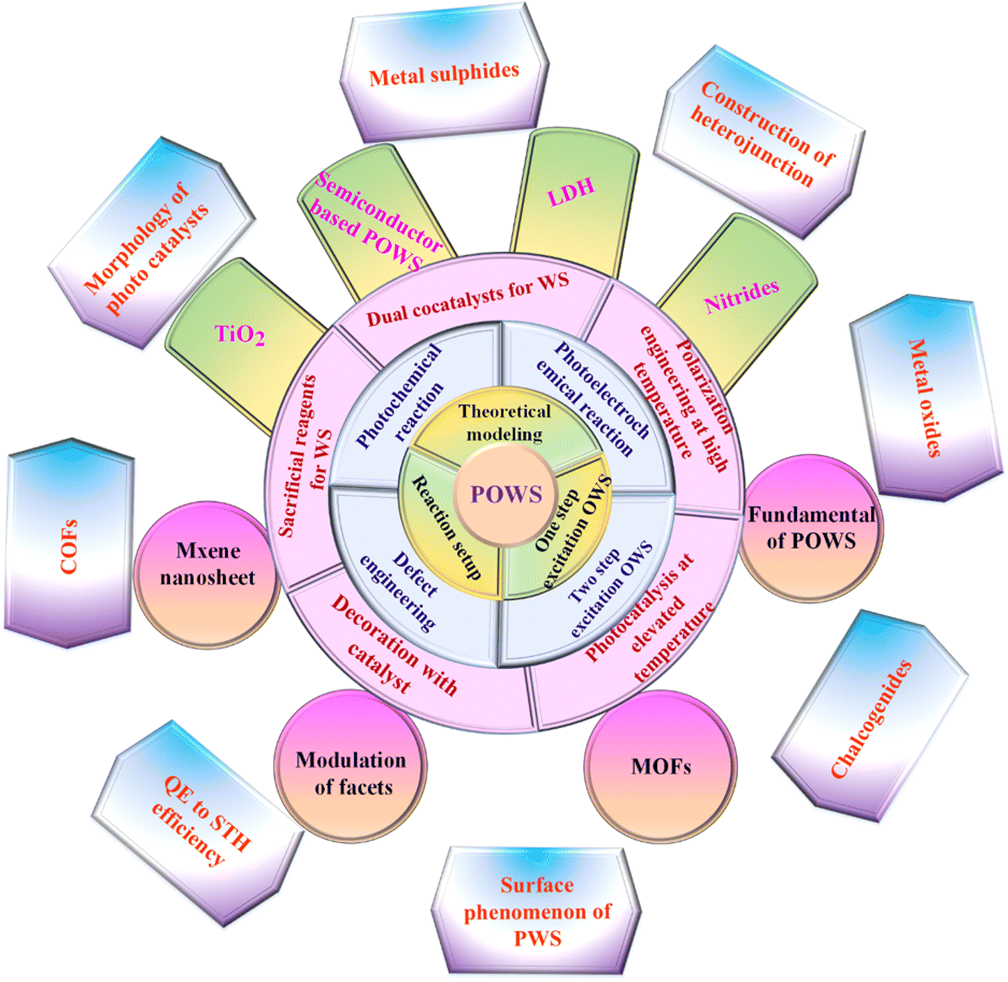
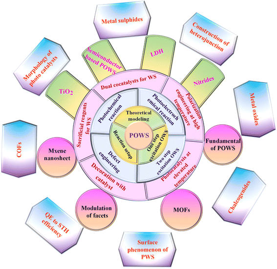
The global growth of urban regions, along with increasingly demanding environmental rules, has led to a substantial surge in global fuel consumption and an increasing of ecological degradation.1–5 Renewable energies are pivotal in revitalizing the transportation and economic sectors, comprising nearly 90% of renewable energy and contributing to decreasing of greenhouse gas and aerosol emissions, including carbon dioxide (CO2). As a result, their is a significant decrease in the use of carbon-containing materials for constructing positive additions.6–8 In 2013, global fuel expenditure reached 17 TW. It is expected to almost get thrice by 2050.9 Developing a clean and sustainable fuel source is crucial for reducing the impacts of carbon emissions, such as global warming, and addressing issues such as depletion of fuel inventory levels, asset specificity, and dependence on sizeable global fuel suppliers.10–13 There are numerous substitutes for traditional fuel resources, such as wind, solar thermal, hydroelectric, and photovoltaic, which are cleaner and more sustainable than traditional energy sources. However, every alternative has limitations that make the move away from traditional fuels harder to accomplish. For example, wind power resources cannot store the energy they generate.14 The reconstruction limitations impede geothermal power development owing to high costs and probable environmental implications. Similarly, while solar electricity is a renewable source, it has a limited lifetime and hence incurs significant operating costs.15 Nonetheless, solar radiation is unlimited, sustainable, independent, and capable of producing electric energy or temperature without requiring expensive turbine blades or installation. On one hand, solar radiation on planet's surface may generate enough fuel to power it for a continuous year.16–18 On the other hand,the quantity of energy produced by natural light is limited by geological location, time of day, duration, and weather conditions.19,20 Another drawback of renewable radiation is the variation in light intensity across the different regions of Earth.21 Developing a recyclable, clean, consistent, and sustainable fuel is imperative to meet the global demand. The primary objective of renewable energy exploration is to generate an artificial photosynthesis system capable of effectively converting sunlight into chemical fuel.22 Plants carry out the procedure of transforming energy through natural photosynthesis, whereby CO2 and water are alternately transformed into oxygen and carbohydrates by using visible light. Utilizing synthetic photocatalysts to imitate this procedure and separate water into hydrogen (H2) and oxygen (O2) is an attractive method for generating environmentally friendly and sustainable H2 fuel.23–25 Considering its remarkable nature, the existing photocatalytic systems and compounds are not yet suitable for real-world deployment owing to their poor solar-to-hydrogen (STH) conversion rate, which is generally under 1%.26 To achieve this objective, it is crucial to use an organized strategy to develop and produce water-splitting (WS) photocatalysts that exhibit exceptional efficiency. These photocatalysts should be capable of exploiting sunlight to break down purified water into equal quantities of H2 and O2, with no need for any other reagents. The exploration of this WS system has continued since 1980.24,27,28 Since then, several materials with the ability to produce H2 and O2 from pure water have been discovered. Nevertheless, the majority of the materials consist of inorganic semiconductors, which possess optical and electrical characteristics that can only be adjusted within a specific range of values. Throughout this work, we describe photocatalytic overall water splitting (POWS), including theoretical modeling, reaction conditions, core design ideas, current breakthroughs in different photocatalyst synthesis, multiple parameters for enhancing POWS, and potential future outlook for such a unique process as summarized in Fig. 1.
 |
| | Fig. 1 The overview of all aspects of this review. | |
1.1. Fundamentals of photocatalytic overall water splitting (POWS)
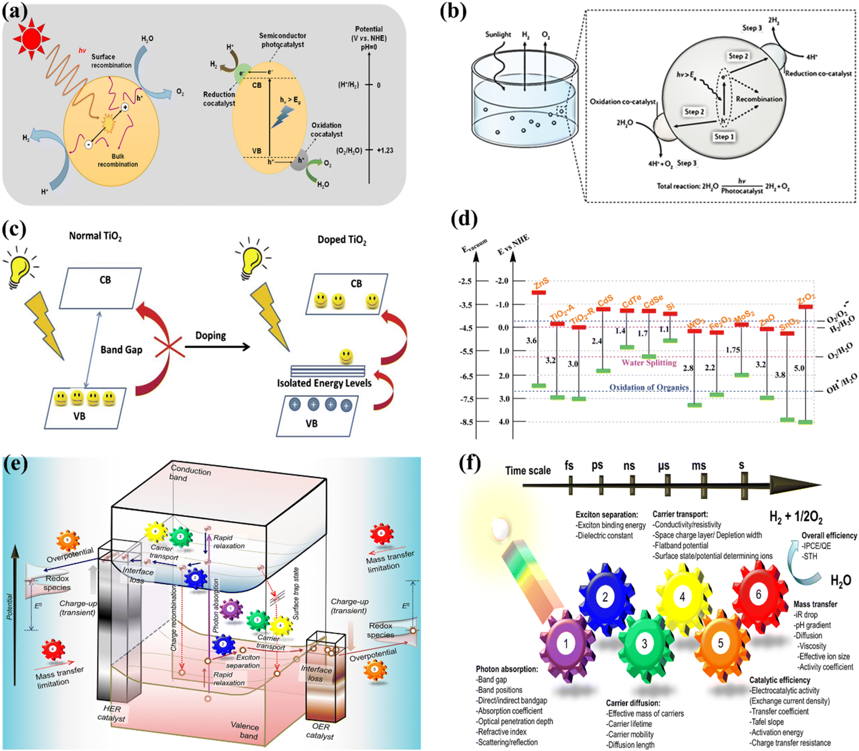
OWS refers to a thermodynamically unfavorable process (ΔG > 0), requiring external energy input to facilitate the decomposition of H2O into H2 and 1/2O2.29–35 In heterogeneous photocatalysis, the utilization of light serves as the external energy source, providing the necessary energy input to facilitate OWS. The photocatalytic process initiates when photons are absorbed, and their wavelengths either match or exceed the energy level of the band gap. The energy state of the photocatalyst needs to align with the thermodynamics of WS (into H2 and O2) to facilitate the efficient execution of the process. The pH level of water plays a crucial role in influencing these reactions. The semiconductor must possess a minimum band gap of 1.23 V under standard conditions to meet the thermodynamic criteria. Specifically, the potentials of the valence band (VB) and conduction band (CB) should be 1.23 V and 0 V, respectively. Beyond thermodynamic considerations, an additional overpotential is necessary to surmount the activation energy barrier associated with the hydrogen evolution reaction (HER) and the oxygen evolution reaction (OER). This overpotential enables the production of H2 and O2 at a measurable rate.36 The effectiveness of the photocatalytic process in converting light energy into the chemical energy of the resulting products is influenced by a multitude of factors.37–44 The initial separation of charges induced by the light occurs within a very short time frame (∼femtoseconds), leading to the separation of charges.45,46 However, this is followed by undesired electron–hole recombination, which can occur within the picosecond to millisecond time range. This recombination can happen either at the site where charge separation occurred (known as “geminate recombination”) or after charge carriers have migrated and randomly encountered each other. The efficiency of the overall process is greatly influenced by the occurrence of charge recombination through any of these pathways.45–48 Several factors constrain the efficiency of a photocatalyst. One such limiting factor is the occurrence of the OWS back reaction, which leads to the generation of H2O from the produced H2 and O2. This reaction is thermodynamically favored with a ΔG = −237 kJ mol−1.37,38 The significance of this reverse reaction increases when co-catalysts, such as platinum (Pt) nanoparticles, are introduced (Fig. 2a and b).26,49 These nanoparticles are recognized for their ability to enhance traditional catalytic or photocatalytic H2 reactions involving O2.50 In terms of photocatalysis, it is possible for electrons and holes to undesirably react with O2 or H2, resulting in the formation of O2·− and H+, respectively. Even though it has not been extensively researched, the overall efficiency of photocatalysis can also be influenced by mass transfer limitations.51 In the case of porous solids, diffusion plays a significant role as it can affect gas evolution due to factors such as pore size, adsorption capacity, hydrophilicity, speed of stirring, or reactor.
 |
| | Fig. 2 (a) Schematic representation of POWS. Adapted from ref. 49. This article is an open access article distributed under the terms and conditions of the Creative Commons Attribution (CC BY) license, (b) diagram depicting the fundamental steps involved in the POWS process. Adapted from ref. 26. Copyright © 2017, Springer Nature, (c) illustration of the process by which the band gap of TiO2 is reduced with the inclusion of anions. Adapted from ref. 60. Copyright © 2015, Elsevier, (d) the band gap energy, and the VB and CB for various semiconductors via NHE. Adapted from ref. 62. Copyright © 2015, Royal Society of Chemistry, (e) illustration depicting the procedure of PWS. A gear corresponding to the numerical value signifies the sequential arrangement of the photocatalytic reaction required for the effective achievement of OWS, (f) photocatalysis factors. OWS is efficient when all six gears represented in the design operate with significant efficiency. This is an open access publication licensed under CC-BY-NC-ND.65 | |
1.2. Semiconductor based photocatalytic water splitting
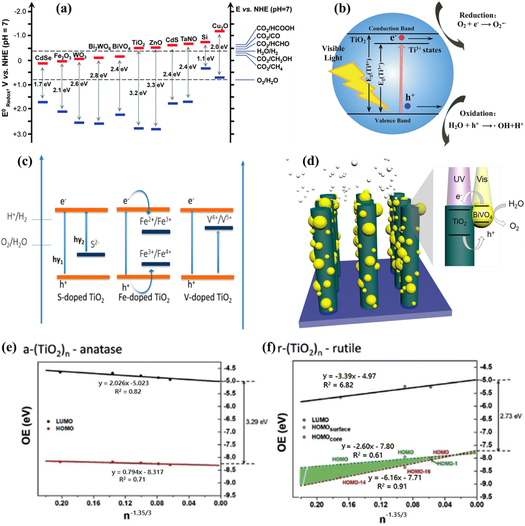
Both half reactions of WS were thoroughly studied to examine the correlation between the photocatalyst structure and their properties and achieve the desired WS performance. In the H2 and O2 evolution process, a sacrificial reagent is commonly adopted to enhance yielding. Adding a sacrificial agent to a catalyst may catalyze both reactions, but it may not be sufficient for OWS. A photocatalyst with a 2![[thin space (1/6-em)]](https://www.rsc.org/images/entities/char_2009.gif) :1 ratio is employed to directly produce H2 and O2 from water. Numerous research and review articles have proposed mechanisms for the photo-assisted PWS process.52–58 The process begins with photon absorption, which produces electron–hole pairs, that have a high probability of initiating the reaction. Subsequently, the photogenerated hole pairs migrate to the catalyst surface to interact with active sites.59 Ultimately, photogenerated electrons are responsible for converting water molecules into H2, while holes are responsible for oxidizing water molecules to form O2−. Similarly, Fujishima and Honda were the first to show the PWS capabilities of a TiO2 electrode in their landmark research.29 Since then, research into WS using semiconductor materials has predominantly focused on heterogeneous catalysis. More importantly, various WS research studies on semiconductor materials have been conducted primarily using heterogeneous catalysis. Semiconductors have a non-overlapping CB and VB, and the photochemical energy accelerates electrons into the CB, resulting in electron holes in the VB and a surplus of electrons in the CB (Fig. 2c).60 These electron–hole pairs are crucial in the redox reactions that occur during WS. Electrons convert protons into H2, while anions oxidize holes (O2−). For the redox reaction to begin (normal hydrogen electrode, NHE), the VB must be higher than the water oxidation level (EO2vs. H2O, 1.23 eV vs. 1.23 eV). To achieve a bandgap of 1.23 eV, WS catalysts are preferred. The possible materials for PWS include KTaO3, ZrO2, SrTiO3, BiVO4, TiO2, and BiVO4, owing to their diverse photocatalytic properties.61 However, photo-corrosion causes conventional semiconductors such as SiC, ZnO, and CdS to lose their capacity to operate as WS catalysts (Fig. 2d).62 Photo-corrosion occurs when photogenerated holes oxidize the anion in the catalyst. Moreover, most semiconductor catalysts operate only under ultraviolet (UV) light, which accounts for only 4% of total solar energy, limiting their efficiency. Similarly, visible light photocatalysts are highly beneficial to enhance solar energy efficiency, as visible light accounts for almost half of all solar energy, and semiconductor materials with bandgaps less than 3 eV can respond to visible light. The addition of carbon or precious metal particles to semiconductor catalysts can improve their visible light response. Furthermore, photocatalysts that employ metal sulfides or nitrides can split water under visible light, as reported in studies.63,64Fig. 2e illustrates the utilization of a singular semiconductor particle as a photocatalyst, adorned with HER and OER catalysts on its surface, having the objective of accomplishing OWS. The mechanism is started by the absorbance of photons, as seen in the center of Fig. 2e. When radiation is absorbed, a VB generates exciting holes, and a CB generates exciting electrons. This process occurs within a femtosecond period. When a quick release process occurs within femto- to picoseconds, an excited state (consisting of electrons/holes) is divided into free carriers. The surface layer of materials then directs the electrons/holes towards the HER and OER catalysts, thereby typically within the range of nano- to microseconds. Fig. 2f depicts a six-gear idea illustrating the successive occurrence of the PWS reaction at multiple intervals. Photon absorbance triggers irregular photo–physiochemical reactions. The photon absorbance results in the formation of stimulation, which is the activation of a single electron from the VB to the CB. The possibility of occupying these positions is mostly governed by the electronic framework of semiconductors, namely the spatial migration of particles.65
:1 ratio is employed to directly produce H2 and O2 from water. Numerous research and review articles have proposed mechanisms for the photo-assisted PWS process.52–58 The process begins with photon absorption, which produces electron–hole pairs, that have a high probability of initiating the reaction. Subsequently, the photogenerated hole pairs migrate to the catalyst surface to interact with active sites.59 Ultimately, photogenerated electrons are responsible for converting water molecules into H2, while holes are responsible for oxidizing water molecules to form O2−. Similarly, Fujishima and Honda were the first to show the PWS capabilities of a TiO2 electrode in their landmark research.29 Since then, research into WS using semiconductor materials has predominantly focused on heterogeneous catalysis. More importantly, various WS research studies on semiconductor materials have been conducted primarily using heterogeneous catalysis. Semiconductors have a non-overlapping CB and VB, and the photochemical energy accelerates electrons into the CB, resulting in electron holes in the VB and a surplus of electrons in the CB (Fig. 2c).60 These electron–hole pairs are crucial in the redox reactions that occur during WS. Electrons convert protons into H2, while anions oxidize holes (O2−). For the redox reaction to begin (normal hydrogen electrode, NHE), the VB must be higher than the water oxidation level (EO2vs. H2O, 1.23 eV vs. 1.23 eV). To achieve a bandgap of 1.23 eV, WS catalysts are preferred. The possible materials for PWS include KTaO3, ZrO2, SrTiO3, BiVO4, TiO2, and BiVO4, owing to their diverse photocatalytic properties.61 However, photo-corrosion causes conventional semiconductors such as SiC, ZnO, and CdS to lose their capacity to operate as WS catalysts (Fig. 2d).62 Photo-corrosion occurs when photogenerated holes oxidize the anion in the catalyst. Moreover, most semiconductor catalysts operate only under ultraviolet (UV) light, which accounts for only 4% of total solar energy, limiting their efficiency. Similarly, visible light photocatalysts are highly beneficial to enhance solar energy efficiency, as visible light accounts for almost half of all solar energy, and semiconductor materials with bandgaps less than 3 eV can respond to visible light. The addition of carbon or precious metal particles to semiconductor catalysts can improve their visible light response. Furthermore, photocatalysts that employ metal sulfides or nitrides can split water under visible light, as reported in studies.63,64Fig. 2e illustrates the utilization of a singular semiconductor particle as a photocatalyst, adorned with HER and OER catalysts on its surface, having the objective of accomplishing OWS. The mechanism is started by the absorbance of photons, as seen in the center of Fig. 2e. When radiation is absorbed, a VB generates exciting holes, and a CB generates exciting electrons. This process occurs within a femtosecond period. When a quick release process occurs within femto- to picoseconds, an excited state (consisting of electrons/holes) is divided into free carriers. The surface layer of materials then directs the electrons/holes towards the HER and OER catalysts, thereby typically within the range of nano- to microseconds. Fig. 2f depicts a six-gear idea illustrating the successive occurrence of the PWS reaction at multiple intervals. Photon absorbance triggers irregular photo–physiochemical reactions. The photon absorbance results in the formation of stimulation, which is the activation of a single electron from the VB to the CB. The possibility of occupying these positions is mostly governed by the electronic framework of semiconductors, namely the spatial migration of particles.65
Due to the strong electronegativity of oxygen atoms, conventional PWS employs transition metal oxides to generate stable compounds.66 These oxides are classified into two groups based on the configuration of their d orbitals. Titanium (Ti), vanadium (V), niobium (Nb), and tungsten (W) possess a low VB energy as a result of their insufficiently occupied d orbitals. Furthermore, the oxygen 2p orbitals significantly impact their VB, resulting in materials with large band gaps and inefficient photocatalytic activities. Various methods have been applied to improve their light-absorbing efficiency, including doping and defect formation. For example, Bo Yan et al.67 used high-temperature hydrogenation to make defect-enriched black TiO2, which showed outstanding photocatalytic activity for the HER (Fig. 3a). In contrast, Co, Mn, Fe, and Ni have occupied d orbitals, and their oxides have small band gaps and strong d–d transitions. Iron(III) oxide (Fe2O3) is a typical example of this category due to its abundance and low cost.68 However, a drawback of transition metal oxides is their low conductivity. To overcome these constraints, multiple metal oxides have been designed. Besides, the photocatalytic activity of metal nitrides and metal sulfides has also been boosted. Bismuth vanadate (BiVO4) is a commonly studied ternary oxide with extensive research on its photocatalytic activity.69–71 The electronic conductivity of BiVO4 can also be improved by mixing it with cations such as Ag+, V5+, and W6+, resulting in enhanced catalytic activity as depicted in Fig. 3b.72 Other ternary oxides that can alter the band gap are CuWO4, ZnFe2O4, CaFe2O4, CuBi2O4, and CuNb3O8.73–76 The combination of nitrogen substitution with metal doping may reduce the band gap resulting from elevated 2p orbital energy levels. Reports indicate that the VBs of sulfur and selenium, which are located at higher energy levels, might generate materials with shorter energy gaps than oxides. These energy gaps are similar to those of nitrogen.77,78 The higher-lying p bands of sulfur and selenium, like nitrogen, generate materials with narrower band gaps than oxides.79–81 Photoactive materials have been synthesized using silicon, III–V semiconductors, and carbon-based compounds.82–84 Aside from the turnover frequency (TOF), the photocatalyst material, stability, and light source should all be considered. As a result, the HER should not be the primary means of evaluating the system performance of the photocatalyst material. The electron–hole pairs are generated at the catalyst surface to catalyze WS and therefore the critical issue in this process is electron and hole recombination.52–54 During photogeneration, electron–hole pairs can immediately recombine before activating redox reactions that yield photons or heat energy. Electrons and holes are more likely to recombine before photocatalysis due to surface defects, which can lower the photocatalytic activity. In general, several defects and smaller particles impede electron and hole recombination, as shown in Fig. 3c.85 Surface defects are reduced in high crystallinity and stoichiometry materials, which enhances the WS reaction. Due to the small diffusion pathways provided by nanoparticles, recombination is reduced. Charge carriers can interact effectively with surface-active sites because small particles have a large surface area (SA). The reaction between electrons and holes at active sites results in the generation of H2 and O2 sources. The intrinsic activity and number of active sites on the surface significantly impact this phase. The reaction won't proceed even if the electrons and holes reach the surface if there aren't enough active sites available. Since the lowest CB values in many transition metal oxides are negative, co-catalysts such as precious metals and nickel oxide are required to initiate the HER.52 However, assuming that the VB of the metal oxides is sufficiently positive, in that case, water can be oxidized to O2 without co-catalysts (Fig. 3d). Particle size and crystallinity are also essential for the WS reaction because they provide more accessible active sites and SA for high activation. Unlike other processes such as dye degradation, the adhesion of the reactant water molecules in WS is insignificant. Although converting WS to H2 and O2 is not thermodynamically beneficial due to the large energy requirements, a reverse reaction is more feasible. Therefore, separating and removing the generated H2 and O2 sources is crucial.
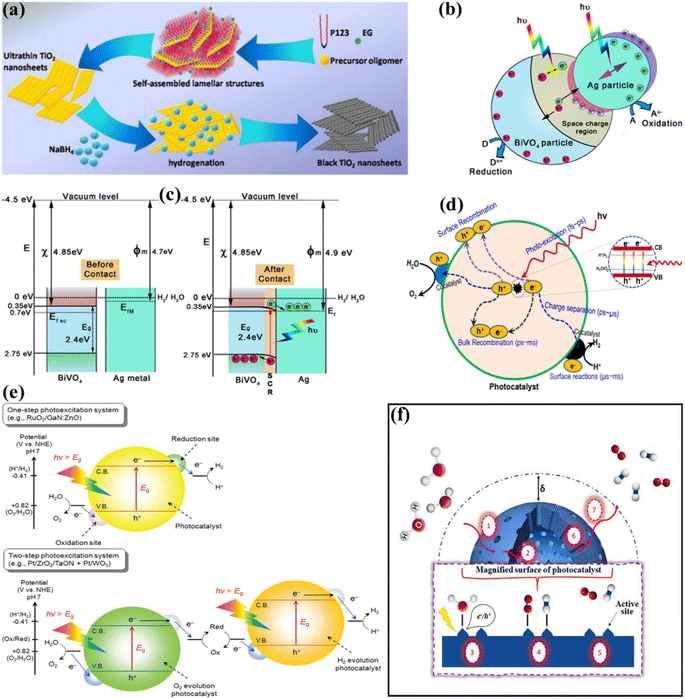 |
| | Fig. 3 (a) Schematic of the synthesis of the ultrathin black TiO2 nanosheets. Adapted from ref. 67. Copyright © 2016, Royal Society of Chemistry, (b and c) schematic illustration of the photocatalytic mechanism of the Ag/BiVO4 M-SC nanocomposite photocatalyst:the showing space charge area due to plasmonic action and band bending with aligned Fermi levels (b and c). Adapted from ref. 72. Copyright © 2016, John Wiley and Sons, (d) basic principles of PWS using semiconductors. Adapted from ref. 85. Copyright © 2017, Elsevier, (e) schematic representation of PWS via one-step and two-step photoexcitation. Adapted from ref. 88. Copyright © 2010, American Chemical Society, (f) seven catalytic steps involved in heterogeneous PWS. Adapted from ref. 44. Copyright © 2021, Elsevier. | |
1.3. Thermodynamics of photocatalytic water splitting
From a thermodynamic perspective, the process of converting WS into H2 and O2 represents an endothermic reaction. Eqn (1) demonstrates that a typical Gibbs free energy shift ΔG0 of +237 kJ mol−1 is required.| | | H2O → 1/2O2 + H2; ΔG0 = +237 kJ mol−1, E0 = 1.23 eV | (1) |
| | | 2H+ + 2e− → H2 (E0Red = 0 eV) | (2) |
| | | 2H2O → 4H+ + 4e− + O2 (E0ox = 1.23 eV) | (3) |
| | | Band gap (Eg, eV) = 1240/λ(nm) | (4) |
To accomplish a thermodynamic non-spontaneous process using photocatalysis, additional energy from photons, above from 1.23 eV potential barrier, must be supplied to the interaction by the catalysts. This potential is subsequently transformed into chemical energies in the resulting molecules. Hence, the catalyst must possess an energy gap (Eg) that exceeds 1.23 eV to accomplish WS. This implies that its absorption edge wavelengths (λ) should be less than 1000 nm, as stated in eqn (4). To comprehend the visible spectrum, its energy must be less than 3.0 eV, which corresponds to an absorbing border wavelength of more than 400 nm, as stated in eqn (4). In addition, to enhance the oxidation and reduction process of H2O through photoinduced electron and hole pairs, it is necessary to align the band alignment of the catalysts with the redox capability of water. To provide the motoring effect for the oxidations/reductions of water, the CB of the photocatalyst ought to possess a higher negative perspective than the reduction capability of H+/H2 (0 eV vs. NHE, pH = 0), whereas the VB ought to have a more positive perspective than the oxidation perspective of O2/H2O (1.23 eV vs. NHE, pH = 0). It is important to observe that the band boundaries of the semiconductor catalyst typically show a pH dependent status (as shown in eqn (5)). Additionally, the redox capacities of water also demonstrate an inverse pH dependency with a slope of 0.059 V pH−1. Consequently, there is no variation in the overpotential of photoexcited electrons for water redox at various pH levels.86,87
| | | ECB = E0CB (pH = 0) − 0.059 pH | (5) |
1.4. Surface phenomena of photocatalysts during water splitting
When seen as a solid–liquid heterogeneous reaction, compressive WS has seven essential steps (as shown in Fig. 3e). The start of the surface reaction needs the diffusion of H2O molecules over the solid–liquid surface, allowing them to reach the external surface of photocatalysts, as shown in step 1 of Fig. 3e. The thickness of the boundary layer determines the rate of convective diffusion rate (δ) and it is commonly increased as this layer becomes thinner due to uncertain mixing. Besides the exterior surface, the interior surface, which is determined by its porosity, is also significant in addition to the outwards, because the pores of the photocatalyst can contain substantial active sites. Therefore, this study also considers the internal diffusion (step 2) to determine how H2O is transported from the exterior to the interior surface. However, due to the nanoscale dimensions of the pores, disturbances in the reaction substrate have not been regarded as significant in the current phase. Historically, the development of nano-sized photocatalysts has focused for optimizing internal diffusion and maximizing SA to facilitate efficient WS. The sequence of steps (3, 4, and 5) depicted herein demonstrates the surface reaction, wherein H2O molecules are adsorbed onto the active sites, followed by their transport through diffusion. Subsequently, the water molecules dissociate into H2 and O2, and the resulting products are released from the active sites, completing the WS cycle. The process of WS relies on the utilization of the electron–hole pair formed during photo-absorption, which is dependent upon the specific characteristics of the photocatalysis involved. Following the completion of the surface reaction, the desorbed products are subsequently transported through diffusion in the opposite direction (steps 6 and 7). During the concluding phase, the gaseous products are discharged as a collective mass. Fundamentally, the phases depicted in Fig. 3f are sequential and overlapping. In the context of photocatalysis, it is critical to enable quick recharging and WS molecules at active sites (steps 3 and 4, respectively) to efficiently inhibit undesired charge recombination. This is crucial due to the highly reactive nature of the photogenerated charge species. Similarly, the rapid desorption of H2 and O2 (as described in step 5) is critical in preparing the currently occupied active sites for successive cycles of reactions. The kinetics of these processes also depend on the diffusional transport explained in stages 1, 2, 6, and 7, respectively. Consequently, the overall rate of PWS will slow down.
1.5. Quantum efficiency and solar-to-hydrogen efficiency
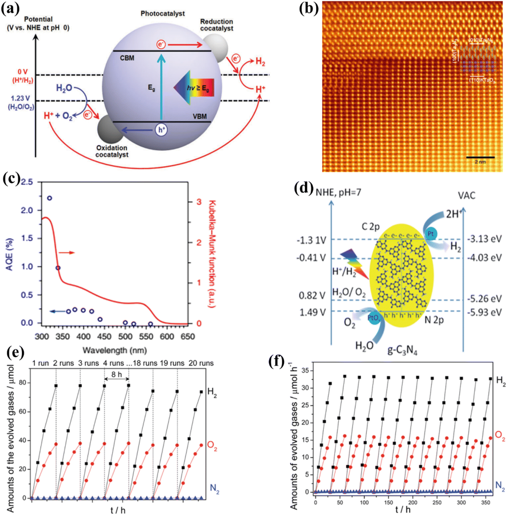
The phenomenon of quantum yields, which refers to the frequency whereby molecules act like photons taken during a specific time, is a key concept in the field of photocatalysis. Photocatalytic researchers regularly measure the quantum efficiencies of reagent degradation, product formation, photon emissions, and various other photochemical reactions and photophysical phenomena that take place in photochemical processes.89 In the field of heterogeneous photocatalysis, quantum yield has been employed to measure the ratio of reacting electrons to the entire quantity of photons that integrate the system during the reaction. This measurement is performed without considering the specific reaction symmetry or the type of irradiation deployed. It differs from the normal measurement in uniform photochemistry, which focuses on the quantity of consumed photons at a specific wavelength. The quantum yield in heterogeneous systems may be determined using an identical approach as for conventional photochemistry, provided that the quantity of consumed photons or the proportion of photons captured by the solid-state photocatalyst can be measured. Due to the substantial dependence of the performance of photocatalysts on experimental situations such as light quantity and reaction temperatures, comparing the functions of different catalysts can prove challenging.90 It is important to emphasize that the real quantum yield must be compared to the interior quantum efficiency (IQE), which is determined by dividing the number of reacting electrons by the number of absorbed photons. The measurement of the quantity of photons captured by a particle-based catalyst in a dispersion environment is challenging due to the phenomena of light dispersion and losses. To get a 100% IQE, every single photoinduced electron must relocate to surface reaction locations before performing bulk mixing. Furthermore, the HER must encompass the insertion of two electrons, while the OER requires the insertion of four holes. These infusions must take place sequentially with no reverse charge movement. Nevertheless, the scarcity of WS demonstrations with an exterior quantum efficiency (EQE) of over 50% is mostly attributed to the numerous possibilities for reverse transmission of electrons, despite the deployment of catalysts sensitive to UV light. Strontium titanate (SrTiO3) is an appropriate material for evaluating the feasibility of this option in photocatalysis. This material is a highly investigated catalyst with a band gap of 3.2 eV.91,92 Throughout decades, its efficiency for WS can be enhanced up to 69% by several improvements.93,94 By selecting and placing highly reactive cocatalysts for the HER and OER on SrTiO3:Al particles, researchers were able to maximize the EQE to its highest achievable value. The achievement was attained by employing a sequential photo-deposition technique rather than an impregnating approach, leading to the uncontrolled distribution of the co-catalysts. Fig. 4a demonstrates the WS capability of SrTiO3: Al, which has been enhanced by loading it with Rh, Cr, and Co particles as co-catalysts. These co-catalysts were incorporated using alternative photo-deposition or traditional impregnating techniques. The photocatalyst, including 0.1 wt% of Rh and later 0.05 wt% of Cr2O3, performed a two-phase photodeposition process. As a result, it produced H2 and O2 in the predicted stoichiometric proportion for WS.88 The WS efficiency reached its maximum level when the concentrations of Cr and Co were both 0.05 wt% (Fig. 4b). The main difficulties confronting POWS are primarily associated with the narrow spectrum of visible light sources that can be utilized, the significant recombination of electron–hole pairs generated by light, the significant potential required for surface catalysis, and the undesired recombination of H2 and O2 produced through conventional photocatalysts. These issues result in a relatively low STH (typically less than 3%) in the majority of the mentioned photocatalytic systems.95,96 The spectrum of light wavelengths to which a photocatalyst may respond determines its greatest possible performance in WS into H2 and O2, known as the computational optimum STH efficiencies. In recent years, researchers have successfully developed indium gallium nitride (InGaN)/gallium nitride (GaN) nanowire (NW) catalysts with precise manipulation of conventional silicon wafers. These catalysts exhibit good crystalline structure and have demonstrated a broad band of sensitivity to visible illumination (400–700 nm), making them acceptable for OWS applications with appropriate band-edge possibilities.97 In this study, Zhou et al.98 presented an apparent temperature-sensitive recombine phenomenon of H2 and O2 in POWS on Rh/Cr2O3/Co3O4-loaded InGaN/GaN NWs. Based on the results of this study, researchers have determined an approach to reaction that is highly efficient. They effectively showed that the POWS response has a performance of approximately 9.2% due to the improved forward H2/O2 formation response and the suppressed H2/O2 replication response at an ideal interaction temperature of around 70 °C. Furthermore, by following this approach, a significant STH performance of 6.2% was attained on a substantial photocatalytic OWS system (Fig. 4c–f).
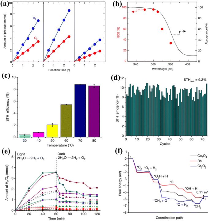 |
| | Fig. 4 (a) Time function for PWS; (b) the provided data include the ultraviolet-visible DRS of untreated SrTiO3:Al (shown by the black solid line) and the relationship between wavelengths and EQE throughout WS on Rh. Adapted from ref. 99. Copyright © 2020, Springer Nature, analysis of efficiency and study of mechanisms. (c) The effectiveness of the Rh/Cr2O3/Co3O4–InGaN/GaN NWs varies with temperatures. (d) This experiment aims to determine the stability of the Rh/Cr2O3/Co3O4-coated InGaN/GaN nanowires. (e) The recombination process between H2/O2 depends on temperatures. (f) Free-energy pattern that shows the process of H2/O2 mixing on the cocatalysts Co3O4, Rh, and Cr2O3. Adapted from ref. 98. Copyright © 2023, Springer Nature. | |
2. Photocatalytic reactions
2.1. Reaction types
2.1.1. Photochemical reactions.
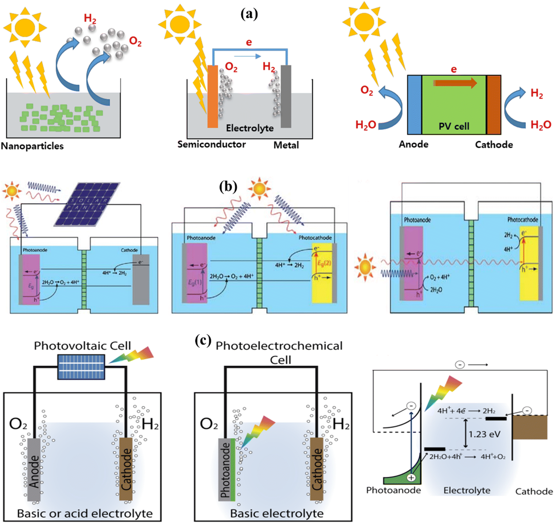
Heterogeneous PWS relies on three essential components: a sacrificial electron donor, a catalyst, and a visible light absorber. Even though the fundamental principles of photochemical and photoelectrochemical systems are identical, their structural configurations differ. In photochemical processes, the WS reaction happens at the surface between an electrolyte and a semiconductor as shown in Fig. 5a. A voltage is needed at the semiconductor–liquid junction for WS to occur. For the semiconductor to be compatible with the electrolyte and avoid corrosion, it must be electrolyte-friendly. The type of product produced, whether it is H2, O2, or OWS depends on the position of the semiconductor band edge.100,101
 |
| | Fig. 5 (a) Solar H2 solutions using a WS containing particulate PWS system, PEC WS system, and photovoltaic–photoelectrochemical hybrid (PV–PEC) system. Adapted from ref. 85. Copyright © 2017, Elsevier, (b) general illustration of PEC. Adapted from ref. 102. Copyright © 2010, Royal Society of Chemistry, (c) solar-driven electrochemical WS cells based on a photovoltaic–electrolysis cell and photoelectrochemical WS cell and the working principle of WS PEC with an n-type semiconductor photoanode. Adapted from ref. 107. | |
2.1.2. Photo-electrochemical reactions.
When a semiconductor photocatalyst is illuminated under UV-visible light having energy equal to or exceeding the band gap of semiconductors, WS occurs, as illustrated in Fig. 5b. The photocatalyst absorbs the energy from the incident light, leading to the separation of charges, specifically electrons and holes, within the VB and CB. Within the CB, photogenerated electrons stimulated by light contribute to the conversion of absorbed H+ into H2, whereas holes oxidize water near the surface of the CB. Depending on the process, semiconductors can be used as either the photocathode or photoanode in PWS. To carry out the entire reaction, a semiconductor electrode must come into contact with a redox pair in PEC WS. This method of illuminating the cathode or anode produces enough voltage for WS. In PEC WS, the reaction is carried out by two separate electrodes.102–104
2.2. Reaction setup
Researchers frequently use experimental setups that include a vacuum pump, a gas chromatograph detector reaction cell, and a gas circulation pump. The quantitative measurements of O2 and H2 production can be determined using O2 and H2 sensors, as well as volumetric methods. To ensure precise measurement of the produced O2, it is essential to eliminate the reaction solution with inert gases before testing, ensuring that the setup is entirely free of air. Various light sources are utilized to initiate the reaction, such as high-pressure mercury lamps combined with a quartz reaction cell for UV-responsive photocatalysts or a 300 W xenon lamp in conjunction with an optical filter for catalysts with band gaps less than 3 eV (Fig. 5c). Additionally, to investigate the generation of solar H2, researchers can utilize a solar simulator. Within the literature, various types of response cells have been documented, including those involving two semiconductors during the 1970s and 1980s, as well as single-junction cells that are recognized as the driving force behind the HER.63,105 However, their low photovoltaic power output is insufficient for efficient OWS. To enhance the WS process, researchers have explored the combination of multi-junction devices and electrocatalysts. A recent study achieved an efficiency of 4.7% by utilizing a monolithic three-junction amorphous silicon solar cell in conjunction with cobalt phosphate and a nickel, zinc, and molybdenum tri-metal catalyst.106
3. Photocatalytic conditions
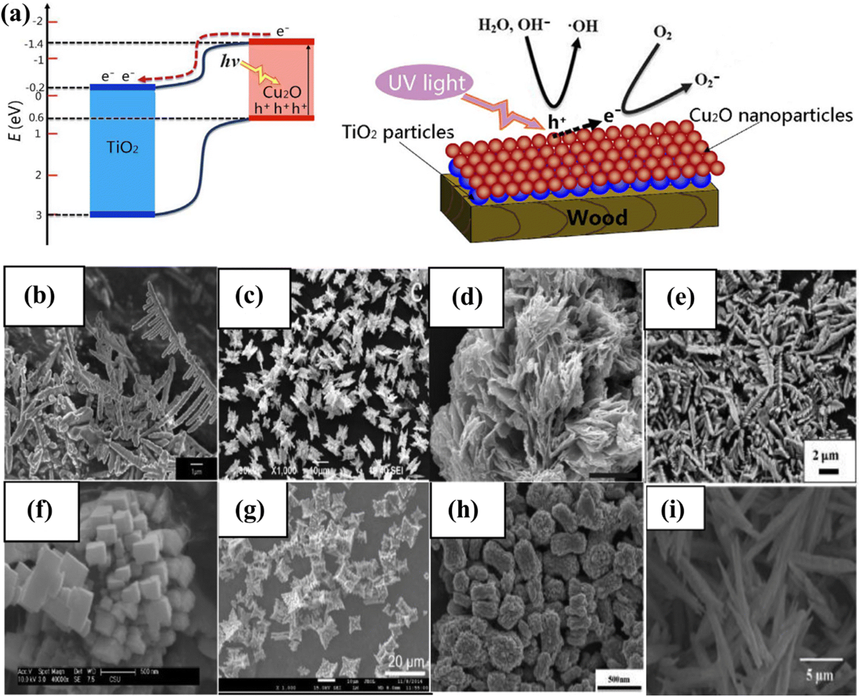
The photocatalytic activity of inorganic catalysts is influenced by several factors, including surface chemistry, junction gaps, particle size and shape, crystallinity, band edge positions, doping, and the depth of entrapment.108 To minimize these factors, various techniques such as hydrothermal, microwave-assisted, surfactant-assisted, and sonochemical synthesis are needed to synthesized photocatalysts.109–112 The fabrication technique has a substantial impact on catalytic activity, especially when structurally active nanoparticles and large SA complexes are utilized. Factors, such as temperature, surfactants, concentration, and pH value, influence the size, shape, and structure of catalysts. The concentration of developing elements in solution influences the nucleation and crystal formation, affecting the activity.113 Co-catalytic systems such as copper oxide and zinc oxide nanowires with a core–shell structure,114 copper/copper oxide heterojunctions with nickel decoration, Fe2O3 nanorod/MgFe2O4 heterojunctions with three-dimensional (3D) cobalt branching,115 and TiO2 anatase combined with copper oxide, have been developed and studied extensively (Fig. 6a).116 The pH value, as well as the hydrothermal temperature, duration, and solvent ratio, all affect the morphology of inorganic photocatalysts.117,118 The geometry of nanostructures in BiVO4 is dramatically altered when the volume ratio of ethylene glycol to water (EG/H2O) is changed from 10/50 to 60/0. The FE-SEM images show lamellar morphologies at 10/50 and 20/40, with 20/40 resulting in thicker sheets. Morphologies resembling leaves, bowknots, sweets, and olives were formed at 30/30, 40/20, 50/10, and 60/0. This is because the increased viscosity and inhibitory effect of EG on crystal formation allow nanocrystals to spin and seek a 3D structure to stabilize them. The morphology of BiVO4 is pH-dependent and ranges from irregular microparticles to hollow microspheres.118
 |
| | Fig. 6 (a) Depiction of the photocatalysis mechanism at the TiO2/Cu2O heterostructures, and a suggested model for the formation of negative oxygen ions on wood treated with TiO2/Cu2O under UV light. Adapted from ref. 116. Copyright © 2016, Springer Nature, (b–i) morphology of BiVO4.144 This chapter is distributed under the terms of the Creative Commons Attribution 3.0 License. | |
3.1. Surface and band structure
Numerous investigations have demonstrated that the chemical characteristics, morphology, and local structure of the catalyst surface play a crucial role in influencing the photocatalytic activity of WS reactions. Chemically modified surfaces are frequently used to improve catalytic activity by reducing corrosion, deactivating undesirable surface states, changing band-edge locations, or selective carrier removal.66,119 However, it's important to note that the surface also governs the trade-off between light absorption and carrier diffusion lengths. Increasing the SA may lead to reduced photovoltage and an increase in surface recombination. As a result, before implementing any surface modifications, an in-depth comprehension of the loss pathways must be acquired.120 CuO with sheet-like morphologies absorbs less sunlight than Cu with spherical morphologies. As the size of the crystallite decreases, the band gaps also reduce.121 BiVO4 is a recent example that has attracted researchers due to its narrow band gap (2.4 eV) and diverse possible morphologies (Fig. 6b–i). Control, suitable structures, and BiVO4 geometry are necessary for photocatalytic performance.122 The photocatalytic performance of BiVO4 varies depending on the specific facets that are exposed.123 These facets include single crystal microspheres,124 octahedral and decahedral nanoplates,117 peanut- and needle-like nanoplates,125 spindly hollow microtubes,126 leaf,127 hyperbranched,128 flower-like,129 porous olive,130 and fusiform.131 Additionally, various shapes of BiVO4 coated with CeOx nanodots,132 BiVO4/TiO2 nanofibers,133 Bi2WO6/BiVO4 composites,134 monoclinic BiVO4/surface rough TiO2 ceramic fibers,135 and m-BiVO4/001-TiO2 heterojunctions have been studied for their photocatalytic performance.136 Band gap engineering is a successful strategy for enhancing photocatalytic performance.137 Assuming that A and B are the junction materials, there are three types: Type 1, where the A material with a higher CB than a material with a lower VB is considered more stable. The natural tendency of electrons and holes to move downward and upward in the direction of lower energy allows them to accumulate in material A. The VB and CB values of material A are less than those of material B, causing charge carrier separation. Type III and Type II junction materials have different CB and VB properties.138 The Type II junction architecture is frequently employed in the fabrication of photocatalyst heterojunctions.139 Charge carrier separation enhanced the activity of CdS/TiO2 and CdS/ZnO heterostructures.140,141 Junction films must be nanostructured to facilitate efficient charge transfer. It is proposed to use a thin layer with charge carrier diffusion to absorb significant amounts of light.66 Using nanostructured BiVO4/WO heterojunctions, near-theoretical photocurrent generation has been realized.142 According to a recent study, photocathodes may carry out the water reduction reaction step in a PEC cell using molecular beam epitaxy and band gap engineering approaches. A layer of SrTiO3, 4 nm thick, is a protective layer for silicon and a charge transport tunnel junction. The coupling of a p-type silicon substrate and a SrTiO3 lattice results in a defect-free surface and low defect density. A photocurrent density of 35 mA cm−2 was attained using 100 mW cm−2 broad-spectrum light and a 450 mV open-circuit voltage.143
4. The importance of developing visible-light-driven water splitting systems
Since 1980, several UV light-driven WS systems have been proposed.145–148 SrTiO3 is an important photocatalyst that works under UV light irradiation. Recently, Al-doped SrTiO3 has been reported to display relatively improved stability and efficiency.93,149–151 However, the production of H2 gas through this process is challenging as the STH values of that system do not match the threshold value achieved with fossil fuels.99 These low values are because the solar spectrum comprises only approximately 5% of UV light (i.e., wavelengths below 400 nm). In contrast, visible light ranges from 400 to 800 nm and constitutes 50% of the total solar spectrum. Hence, employing a photocatalyst capable of using incident solar radiation below 600 nm can provide an STH close to 16% with 100% efficiency.152 For this reason, photocatalysts working at long wavelengths are very efficient in the renewable H2 production process.153
4.1. One-step-excitation visible-light-driven overall water splitting
The application of photocatalysts for one-step excitation in visible-light-driven WS poses significant thermodynamic challenges. Firstly, the band gap energy of the selected photocatalyst must be less than 3.1 eV to ensure the optimal absorption of visible light radiation. Secondly, photocatalysts with narrow band gap energies tend to exhibit low driving forces and limited stability. This is primarily attributed to the reduced potential difference between the valence band maximum (VBM) of photocatalysts concerning the water oxidation potential and the conduction band minimum (CBM) concerning the water reduction potential. As a result of the photogenerated carrier concentration, the photocatalytic materials photo corrode faster. Third, photocatalysts with small band gaps are not well positioned about the redox potentials of water. Thermodynamically, the HER and OER potentials of water should be supported by the CBM and VBM of the photocatalyst for efficient POWS simultaneously. Fourthly, narrow band gaps possessing photocatalysts are likely to be oxidized during the oxidation reaction of water, since they typically consist of N3- and S2-anions; therefore, considering the above-stated reason, only a limited number of photocatalysts meet this criterion for use in one-step-excitation for visible light-induced WS reactions. Alternatively, attention has been given to the utilization of photocatalysts that respond to visible light in the half-reactions of the HER and OER in the presence of sacrificial electron donors and acceptors, respectively.154–162 Since the bottom of the CB is at a possibility that is greater than the H+ to H2 reduction capacity (0 V vs. NHE at pH = 0), then the electrons/holes produced by light and holes can reduce H+ and oxidize H2O, accordingly. Furthermore, as shown in Fig. 7a, the highest level of the VB needs to be situated at a stage that is significantly more positive than the H2O → O2 oxidation capacity (1.23 V vs. NHE at pH = 0).163 Conversely, the HER cannot produce renewable H2 on its own due to its reliance on chemical energy derived from sacrificial reagents, often produced by using fossil fuels. Consequently, this process has limited or no direct utilization of solar energy. Hence, it is imperative to establish a comprehensive WS system that operates without the need for sacrificial reagents. Since the year 2000, many photocatalysts responding to visible light for one-step OWS have been reported.164 Notably, the solid solution of Ga1−xZnxN1−xOx, which can adjust its absorption edge to encompass wavelengths up to 500 nm by altering the component ratio165–167 has enhanced its apparent quantum efficiency (AQE) to 5.1% at 410 nm.168 A subsequent study also found that a low concentration of palladium (Pd) was effective in this context.169 Transition metal oxynitrides and nitrides, such as Ta2O5, TaON, and Ta3N5, have garnered considerable attention due to their high light-absorption properties.170 In particular, Ta3N5 is well-suited for the OER, because it can produce H2 or O2 from aqueous solutions containing sacrificial electron donors or acceptors, all while absorbing visible light up to 600 nm.171 Nevertheless, due to substantial charge recombination at defects, the achievement of OWS remained difficult until 2018. Rapid growth has recently been used to generate Ta3N5 single crystal nanorods with no grain boundaries and cubic KTaO3 particle edges that are lattice-matched.172 Upon the introduction of a Rh/Cr2O3 cocatalyst, these single-crystalline Ta3N5 nanorods exhibited the ability to split water into HER and OER products in a stoichiometric ratio of 2 (Fig. 7b and c). In one-step excitation OWS systems, LaMgxTa1−xO1+3xN2−3x (x1/3) has also been used. The composition of this material can be changed to produce a variety of solid solutions with different band gaps and positions. The OWS was accomplished in 2015 utilizing Ta2/3O2N at wavelengths up to 600 nm after the inclusion of a RhCrOy cocatalyst and layers of amorphous titanium and silicon oxyhydroxide to regulate surface redox processes. Following that, the photocatalyst, cocatalyst species, and coating materials were optimized, resulting in a significant increase in photocatalytic activity during WS.173 For example, changing the Mg and N contents of a solid solution led the VBM to shift to a more positive potential, facilitating water oxidation. Another study employing LaScxTa1−xO1+2xN2−2x (x0.5) reached OWS as a result of this adaptation. Despite these advancements, the AQE values and stability of these oxynitride and nitride photocatalysts remain low, requiring further improvements in crystallinity, particle shape, and surface modifications. Intense visible light absorption has also been observed in metal chalcogenide photocatalysts, such as cadmium sulfide (CdS), which has a band gap value of 2.4 eV and is suitable for general WS. Extensive research on the HER half-reaction has been conducted using this photocatalyst.174 CdS has been employed as a photocatalyst to enable the visible-light-driven OER with the support of surface modifications. In this approach, Pt serves as a reduction cocatalyst and Ru(tpy)(bpy)Cl2 acts as an oxidation cocatalyst.175 Oxysulfide photocatalysts are gaining popularity due to their enhanced stability compared to chalcogenides, all while maintaining effective performance at longer wavelengths. These characteristics are attributed to the hybridization of O 2p and S 3p orbitals within these materials. Initial research demonstrated promising catalytic activity of Sm2Ti2O5S2, which absorbs wavelengths shorter than 650 nm, for both the HER and OER half-reactions, indicating suitable band positions for OWS.176,177 Since the development of OWS with this material utilizing single-step excitation has not yet been reported, further study has focused on improving the production, particle shape, and surface characteristics of this oxysulfide molecule.178,179 A band gap of roughly 1.9 eV is achieved by substituting samarium with yttrium in a solid-state process, resulting in an absorption edge at 650 nm. This specific oxysulfide compound, Y2Ti2O5S2, demonstrated the capability for OWS within a 20-hour reaction period when the HER and OER were facilitated by cocatalysts Rh/Cr2O3 and IrO2, respectively.180 Recently, there has been a growing interest in exploring conjugated polymers that exhibit band structures similar to semiconductors as potential candidates for POWS. Prior studies predominantly concentrated on investigating polymeric carbon nitride (PCN) for photocatalytic half-reactions.181–183 After much effort, OWS under both UV and visible light was achieved by loading appropriate cocatalysts onto PCN (Fig. 7d–f).184–186 In addition, the utilization of traditional cocatalysts, such as single-site cocatalysts, has displayed a notable enhancement in performance. Furthermore, 1,3-diyne-linked conjugated microporous polymer nanosheets (CMPNs) have been synthesized through the oxidative coupling of terminal alkynes.187 These materials have been found to serve as versatile photocatalysts for overall water splitting when exposed to visible light.188
 |
| | Fig. 7 (a) Illustrations showing the conceptual potential of the one-step stimulation of OWS on particulate catalysts. Adapted from ref. 163. Copyright © 2019, Royal Society of Chemistry, (b and c) colorized annular dark-field STEM image of Ta3N5/KTaO3, along with the apparent AQE as a function of the incident light wavelength.171 (d–f) The band positions of PCN and the WS activity under visible light irradiation. Abbreviations: NHE, normal hydrogen electrode; VAC, vacuum. Adapted from ref. 184. Copyright © 2016, Royal Society of Chemistry. | |
4.2. Two-step-excitation visible-light-driven overall water splitting
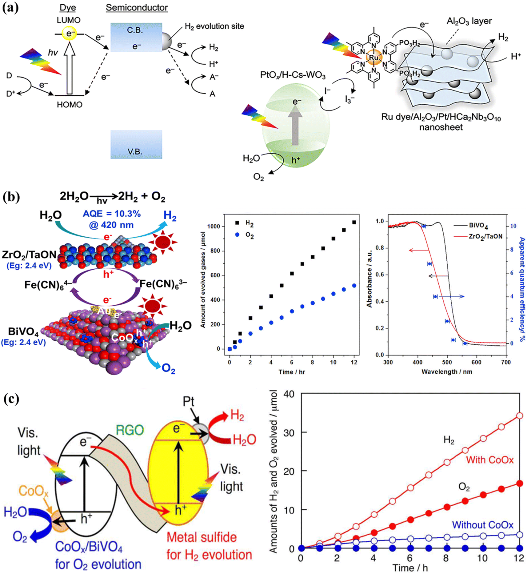
Certain photocatalysts, which respond to visible light, can only be employed for one-step excitation in OWS due to a misalignment between their energy bands and the redox potentials of water. To address this challenge, a two-step-excitation OWS, commonly referred to as Z-scheme WS, has been devised. In this system, photocatalysts are employed for both the HER and the OER, with electron mediators used to prevent the accumulation of excess holes or electrons in each photocatalyst.189 This approach significantly broadens the range of usable photocatalysts, as long as the HER and OER catalysts satisfy the thermodynamic conditions for the corresponding WS half-reactions. The Z-scheme WS systems have been extensively explored using reversible donor/acceptor coupling driven by visible light.190,191 For instance, PtOx/WO3 and IO3−/I− pairings were used as the OER and redox mediator, respectively, while barium-modified Ta3N5 was employed as the HER catalyst.192 Another Z-scheme WS system was synthesized using ZrO2/TaON as the HER catalyst and Pt/WO3 as the OER catalyst, achieving an AQE of 6.3% at 420 nm.193 The AQE value was further improved to 6.8% using MgTa2O6−xNy/TaON as the HER catalyst and PtOx–WO3 as the OER catalyst, although the resulting STH value was low (around 3).194 The hydrogen evolution reaction (HER) in Z-scheme WS system has been successfully demonstrated with Sm2Ti2O5S2, an oxysulfide photocatalyst, coupled with WO3 serving as the oxygen evolution reaction (OER) catalyst and the I3/I redox pair functions as an electron mediator shuttle in this configuration. Additionally, a photocatalytic system based on the Pt/NiS-supported La5Ti2AgO7S5 photocatalyst as the HER catalyst achieved an AQE of 0.12% at 420 nanometers.195 Other oxysulfide photocatalysts, such as La5Ti2CuO7S5 and La6Ti2O5S8, have been found to evolve H2 and O2, despite oxygen being typically produced in a stoichiometric proportion in these systems. Recently, a WS Z-scheme has been developed using HCa2Nb3O10 nanosheets with a Ru(II), tris-diimine type photosensitizer as the HEP, PtOx/H-Cs-WO3 as the OEP, and I3−/I− as the redox mediator (Fig. 8a).196 By modifying the OWS with amorphous Al2O3 clusters, the AQE at 420 nm was increased to 2.4%. This is the highest AQE for an OWS system based on a dye-sensitized photocatalyst ever reported. PCN materials can be used as HER catalysts in Z-scheme WS systems, with BiVO4 or WO3 as the OEP and the electron mediator I3−/I−. Another common redox mediating pair is Fe3+/Fe2+. A Z-scheme system was synthesized in one study using oxychloride Bi4NbO8Cl as the visible-light-responsive OEP and Ru/SrTiO3:Rh as the HER catalysts, along with a Fe3+/Fe2+ redox mediator, which produced H2 and O2 under visible light radiation. Bismuth tantalum oxyhalides such as Bi4TaO8X (X = Cl, Br) have also been discovered to be active visible-light-responsive photocatalysts.197 Similarly, this photocatalyst can function as an OER catalyst in a Z-scheme system with Ru/SrTiO3:Rh as the HER catalyst to stoichiometrically evolve H2 and O2 under visible light. The [Fe(CN)6]3−/[Fe(CN)6]4− shuffle can operate at lower pH levels and has a moderately negative redox potential (E = 0.357 V versus a SHE); thus, a single electron can be accepted/donated in this redox pair. A system based on ZrO2-modified TaON, BiVO4, and [Fe(CN)6]3−/[Fe(CN)6]4− as the HEP, OEP, and redox mediator achieved a remarkable AQE of 10.3% at 420 nm in one study (Fig. 8b).198 Based on the integration of Z-scheme and photoelectrochemical systems, it has been shown that the HER and OER, which are isolated in space and time, can simultaneously develop.199,200 In this hybrid process, a redox couple undergoes reduction, transforming water into O2 while simultaneously converting solar energy into chemical energy. With a minimal applied bias, H2 is generated through the electrolysis of an aqueous solution containing the reduced redox mediator. Through the use of an optimized BiVO4 photocatalyst with a controlled quantity of surface-adsorbed Fe(III) and a redox mediator involving Fe(III)/Fe(II), impressive results were achieved, with an AQE of 38% at 420 nm and a solar-to-electric conversion efficiency of 0.65%.201 Additionally, ionic redox mediators may absorb some of the visible light that is being received by the device or can cause corrosion with certain photocatalysts. Solid-state electron mediators have been used to overcome the drawbacks of ionic ones, and it has been revealed that reduced graphene oxide (rGO) is an efficient carrier of photoexcited charges between the HEP and OEP. Considering this fact, a visible-light-driven Z-scheme WS system was constructed by combining a metal sulfide and CoOx/BiVO4 as HER and OER catalysts, on the rGO sheets (Fig. 8c).202 After the system was exposed to visible light, a steady production of H2 and O2 at the stoichiometric ratio was observed. Z-scheme OWS has also been achieved under visible light irradiation by using PCN as the HEP, BiVO4 as the OEP, and rGO as the electron mediator.203–206 Additionally, some conjugated polymers have been reported to enhance the OWS in association with rGO as the electron mediator respectively.207
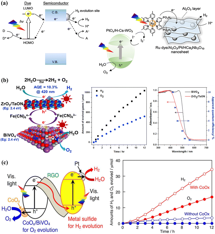 |
| | Fig. 8 (a) Typical visible-light-driven Z-scheme OWS systems using ionic redox mediators. The transfer mechanism and schematic diagrams for Z-scheme WS using Al2O3/Pt/HCa2Nb3O10 nanosheets sensitized with a Ru dye as the HER catalyst and PtOx/HCsWO3 as the OER catalyst. Adapted from ref. 196. Copyright © 2020, American Chemical Society, (b) a schematic diagram of a Z-scheme system using ZrO2/TaON, BiVO4, and [Fe(CN)6]3−/[Fe(CN)6]4− as the HER catalyst, OER catalyst, and redox mediator, respectively, and the time course of OWS under visible-light irradiation, together with the dependence curve of AQE as a function of irradiation wavelength. Adapted from ref. 198. Copyright © 2018, Elsevier, typical two-step-excitation OWS using solid-state electron mediators. (c) A diagram of a Z-scheme WS system using rGO as the solid-state electron mediator and a plot of the activity increase obtained by employing Pt/CuGaS2 as the HER catalyst and CoOx/BiVO4 as the OER catalyst. Adapted from ref. 202. Copyright © 2016, American Chemical Society. | |
5. Strategies for enhanced photocatalytic performance
The efficiency of photocatalytic-based WS processes is affected by several parameters and thus extensive efforts have been made to develop various strategies. One of the valuable strategies to enhance the energy-capturing capability is narrowing the band gap of materials in the visible spectral range.60,208–213 Other methodologies involve the use of organic dyes as a photosensitizer agent to boost the sensitization60 or doping anions/cations to introduce new band levels into the semiconductor materials' band structures to enhance the light absorption capability.211,212 The availability of additional states via electron trapping or intermediate band level modification with the assistance of defects generated by oxygen (in the form of vacancies in the band levels) is also thought to improve the light absorption phenomena.214–216 The engagement of metal oxide and noble metal facilitates the surface chemical reactions by lowering the overpotentials of the OER and HER to suppress the backward reaction resulting in water formation.26,217–222 In addition to this method, various methodologies have been developed to promote electron and hole separation to prevent them from recombination, such as heterojunction formation, facet engineering, internal electric field generation, and so on.223–226 In this section, some key strategies such as decoration with cocatalyst, dual cocatalyst deposition, polarization field engineering, temperature effect, sacrificial reagents system, morphology control, heterojunction formation, modulation of facets, and defect engineering will be investigated specifically with an emphasis on their functioning mechanism. Moreover, recently developed promising approaches based on the polarization effect to extend the exciton lifetime will also be highlighted.
5.1. Defect engineering
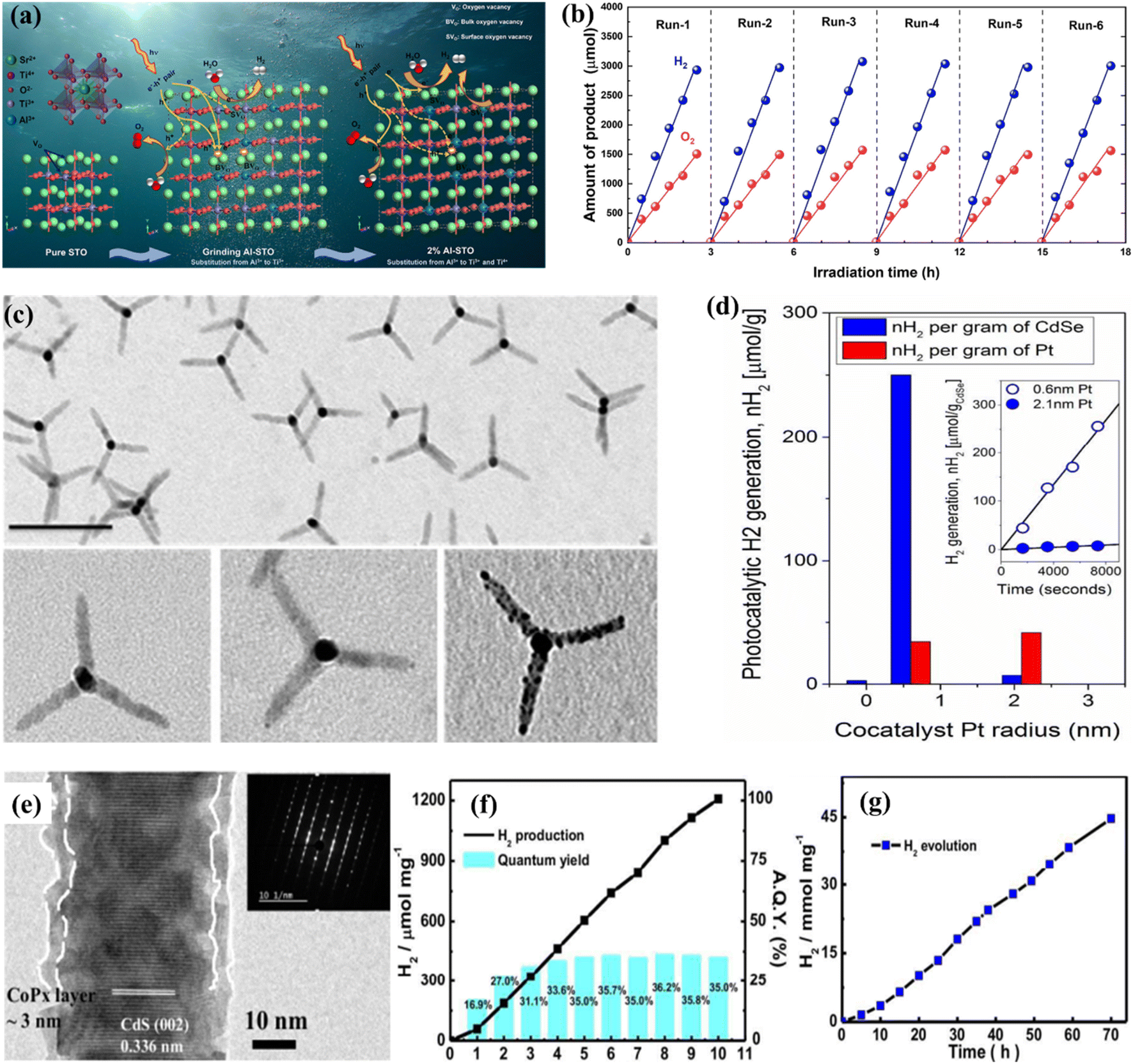
Surface defects that generate vacancies in semiconductor materials are recognized as an efficient way of tailoring their chemical and physical properties such as surface adsorption properties, charge separation, charge density, etc.227–230 One of the most promising strategies is vacancy-based modification. In this context, there has been advancement in the study of oxygen vacancies (Vo) present in TiO2. The low density of Vo that naturally exists in most metal oxides can be improved through ion doping,231,232 plasma surface treatment,233 chemical reduction of NaBH4,234,235 thermal treatment in an environment containing NH3 gas,231,236 and exfoliation to fabricate 2D materials.237 Asahi et al.208 first proposed a strategy based on anion-doped TiO2 for improved light absorption. Consequently, several studies were devoted to this approach by using UV-vis spectroscopy showing that N-doped TiO2 absorption extends to 500 nm. X-ray photoelectron spectroscopy (XPS) confirmed the characteristics of N species, with peaks emerging at 396 eV and 400 eV, respectively, associated with the substitutional and interstitial N species.208,231,236 Mao et al.209 explored hydrogen pre-treatment in their pioneering work, where TiO2 was sequentially treated for five days under a hydrogen atmosphere at a temperature of 200 °C and a pressure of 20 bar. The results were promising, and black TiO2 showed enhanced light absorption along with the photocatalytic HER. Black titania was examined using Raman spectroscopy, indicating that the hydrogenation process introduces defects responsible for activating zone-edges.209 Chang et al.238 effectively synthesized Al3+-loaded SrTiO3 for the OWS performance using the PC technique. The implied materials were analyzed with multiple scientific methods and protocols in comparison to the usual solid-phase milling process. The inductively coupled plasma (ICP) research shows that the Al3+ integration rate of the PC technique was greater compared to that of solid-phase milling. The impact of a high degree of Al3+ injection consistency on the chemical and physical properties and photocatalytic properties of the generated catalysts was thoroughly investigated. The photocatalytic efficiency and function of the Al3+-loaded SrTiO3 catalysts generated by the PC technique were explored depending on the assessment (Fig. 9a and b). However, recent research found that the maintenance ability of surface defects becomes fragile during the catalytic process, especially under high-temperature conditions due to their tendency to regenerate with H2O or O2. In contrast, bulk defects hold their capacity for improved light absorption; still, surface defects are unable to retain their maintenance, leading to poor performance and the suppression of active catalytic sites, which may affect the photocatalytic performance. This also explains that the visible light absorption phenomenon cannot necessarily be linked with enhanced photocatalytic-based WS or AQE.231
 |
| | Fig. 9 (a) Diagrammatic representation of the defective pathway and carrier transport in the 2% and 1% Al-STO catalysts for milling. (b) Evaluation for durability of 2% Al-STO activated with Co (0.05 wt%), Cr (0.05 wt%), and Rh (0.1% wt%) after powder washing. Adapted from ref. 238. Copyright © 2022, Elsevier, (c and d) TEM illustration and photocatalytic performance of pristine and modified CdSe tetrapods. Adapted from ref. 246. Copyright © 2017, American Chemical Society, (e–g) HR-TEM image and photocatalytic performance of amorphous cobalt phosphide cocatalyst modified cadmium sulfide. Adapted from ref. 254. Copyright © 2016, Royal Society of Chemistry. | |
5.2. Decoration with cocatalysts
The use of cocatalysts in PWS garnered increased interest and has been focused extensively. Cocatalysts have been found to aid in charge separation and reduce recombination by promoting the extraction of exciting electrons from manipulating holes, depending on their nature. Photocatalytic-based WS and the HER based on photo-reduction of protons are considered facile processes, but the OER from OH− involves a fundamental step that requires four electrons.163,239 Cocatalysts can promote O2/H2 surface evolution by reducing the activation energy. Metals such as Pt, Pd, Ru, Au, Rh, and Ni are commonly used for H2 evolution, while metal oxides such as Ir, Mn, Co, and Ru are accepted as cocatalysts for the OER.240 Pt is widely used as an H2 evolution cocatalyst, and recent progress has been reported in this regard. However, using cocatalysts for the HER can trigger the reverse reaction, leading to water formation. Bimetallic cocatalysts have been introduced to overcome this issue and promote the forward reaction. The Domen group reported synthesizing a core–shell structure of Rh/Cr2O3 using selective photoreduction, where the Cr2O3 catalyst prevented oxygen access to the metal surface, reducing the possibility of evolved O2. A recent study discovered that Au nanoparticle insertion by photoreduction had a substantial influence on N-doped TiO2, resulting in an elevated H2 evolution rate of up to 90%.231 The Domen group reported the synthesizing of a core–shell structure of Rh/Cr2O3 using selective photoreduction. In their study, the catalyst Cr2O3 species as a barrier prevented oxygen access to the metal surface, reducing the possibility of evolved O2.217,241 The core–shell structure of Rh/Cr2O3 and the presence of Rh and Cr2O3 in the core and shell were confirmed by TEM, XPS, and EXAFS analysis respectively. When GaN: ZnO was loaded onto Rh/Cr2O3, the inhibition of the backward reaction resulted in enhanced WS efficiency. A similar performance was also seen for the metal cores of Pt and Ir.217 Despite the greater SA and shorter range of charge transfer to the reaction liquid, smaller-size cocatalyst particles are commonly selected in photocatalysis.151,242,243 However, smaller-size cocatalysts have the disadvantage of poor visible light, which can decrease their shielding effect.244 Single-atom-based cocatalysts have been focused on due to their small size.245,246 However, some studies have reported that the smallest cocatalysts are not always favorable for catalytic efficiency, indicating another drawback of such cocatalysts.247,248 Similarly, the TEM morphology and the conflictive effects of co-catalysts on pristine and modified CdSe tetrapods regarding the charge transfer efficiency have been depicted in Fig. 9c and d.246 Smaller sizes accelerate the electron moment to access the solution of cocatalysts quickly and are effective in suppressing the phenomenon of electron acceptance from host catalysts to cocatalysts. Another perception of the size dependence is based on the various types of photocatalyst hosts, because each type holds different surface catalysis and charge transfer characteristics.249,250 Despite size, another affecting component is the shape/structure of cocatalysts, which can be critical in determining overall activity.251 Variation in the structure of each entity offers distinctive exposed facets, leading to differences in absorption energy for WS and active sites. To enable efficient cocatalysts, another important morphology is the hollow structure, which offers efficient charge transport and mass transfer as a result of its unique structure.252 Cocatalysts with fewer defects in their crystalline structure have shown good performance. Still, recent studies have highlighted the importance of amorphous cocatalysts.253 These have exhibited excellent charge transfer capability and photocatalytic performance by developing a core–shell structure with amorphous cobalt cocatalysts (CoPx) integrated with CdS nanorods (Fig. 9e–g).254 Amorphous cocatalysts can trap electrons, facilitate proton adsorption, enhance kinetic charge transfer capability and have shown a high AQE of up to 97.42%.255
5.3. Photocatalysis at elevated temperatures
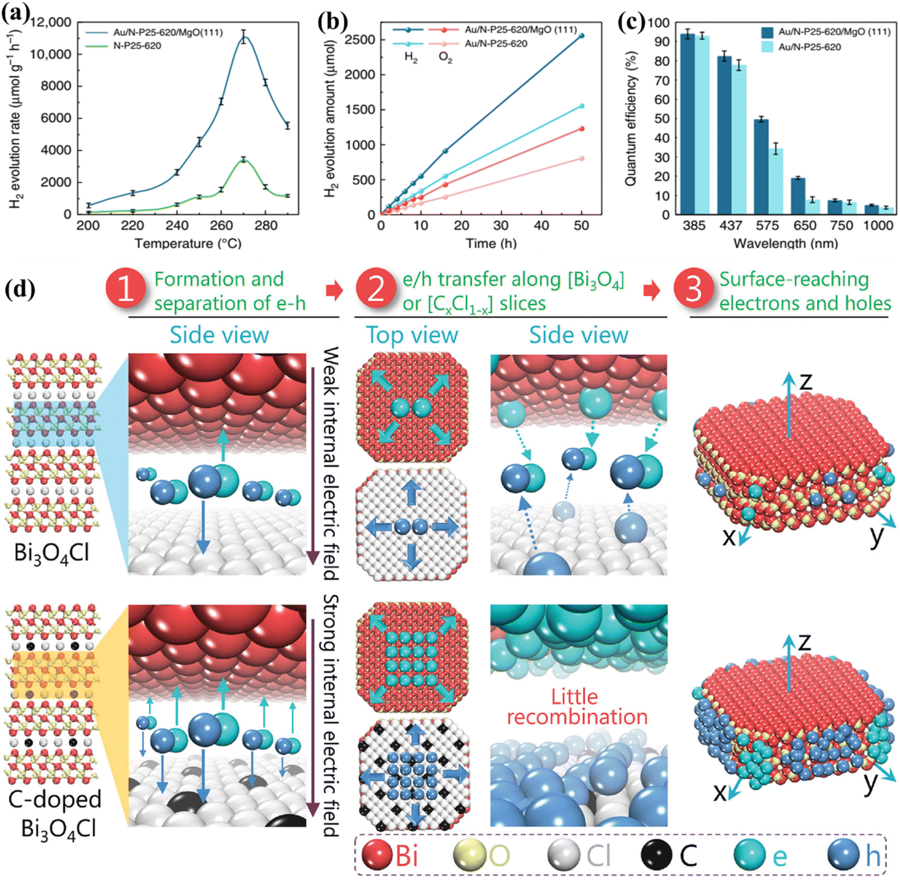
In the past decade, research on PWS has predominantly focused on room temperature conditions. However, it has been shown that raising the temperature can enhance the thermodynamic and kinetic performance of endothermic reactions. The thermolysis process, requiring very high temperatures (around 1000 °C), is impractical for real-world applications.65 Nevertheless, the use of elevated temperatures for efficient photocatalysis offers a new approach to harnessing solar energy, taking advantage of the fact that solar sources can also supply heat. Additionally, nearly 50% of the solar spectrum consists of infrared radiation, which can provide the necessary heat energy through thermal radiation, therefore eliminating the need for expensive electrical devices.256,257 S. C. E. Tsang et al.233 describe an instantaneous PWS method that can successfully use sunlight at high temperatures, with substantially greater H2 production rates and QEs than the Au/N-loaded TiO2/MgO (111) nanocatalyst because of the longer excitation duration in this structure. Consequently, at 270 °C, a wide absorption spectrum appears, generating O2 and H2 sources in a 1:2 molar proportion with an H2 generation activity of about 11000 mol g−1 h−1. The Q.E. spectrum is very remarkable and extends from 81.8% at 437 nm to 3.2% at 1000 nm (Fig. 10a–c). B. Han and Y. Hu258 proposed a photocatalytic HER system based on the temperature-induced mechanism which achieves an AQE of up to 65.7% (with methanol as a sacrificial reagent) at a temperature of 280 °C under visible light. The increase in temperature supplies thermal energy to the reactants, as well as an increase in kinetic driving force, which is responsible for the increase in AQE and the HER. B. Tian et al.259 utilized black phosphorous nanosheets in a PWS process carried out at high temperatures. Their proposed system demonstrated a nine-fold increase in PWS at a temperature of 353 K compared to room temperature, resulting in an increase in QEs up to 42.55%. It should be noted that sacrificial reagents were not considered in their study.259 However, the absence of oxygen in their proposed system makes it susceptible to photo-corrosion of the phosphide catalyst, which is one of the drawbacks. Water dissociation can be promoted up to 25 times compared to the dissociation carried out at room temperature and its high temperature of ∼270 °C making it suitable for enhancing PWS kinetically.41 Despite the increase in performance, it is not frequently reported. With motivation from previous research to encourage WS caused by increasing temperature, an exceptional AQE of up to 81.8% (at 437 nm and 270C) for a TiO2-based photocatalyst was recently reported. It is worth mentioning that an AQE of 3.2% was also testified at 1000 nm, obviously indicating a theoretical threshold for PWS.231 Charge carriers approaching the surface of a photocatalyst are also considered crucial compared to those that settled down in the bulk region.
 |
| | Fig. 10 PWS response function testing. (a) Photocatalytic activity of N-P25-620 and Au/N-P25-620 with MgO (111) at various temperatures. (b) Effective stoichiometric WS with no sacrificial agent over Au/N-P25-620 with and without MgO (111) at an identical speed for 50 h. (c) QE of Au/N-P25-620 in conjunction with and without MgO (111) assuming incoming wavelengths, this is an open access article distributed under the terms of the Creative Commons CC BY license.233 (d) A schematic illustration of Pt along with the separation and migration of electrons and holes in the bulk of pure and C-doped Bi3O4Cl. Adapted from ref. 266. Copyright © 2016, John Wiley and Sons. | |
5.4. Polarization field engineering at elevated temperature
After the light absorption, the charge carriers migrate to the photocatalyst surface.260 Photoexcitation generates electrons and holes in femtoseconds but charge separation and migration typically take much longer respectively. The photoexcited electrons/holes prefer to recombine and release energy in heat instead of traveling to the surface that reacts with chemical species, and therefore this process takes approximately 10−12 s. However, the transfer of charge to the chemical species at the interface is a relatively slow process that occurs in the range of microseconds to picoseconds, showing that electrons and holes prefer recombination instead of migration to the surface.261,262 This implies that only a small number of photoinduced electrons/holes emitted by photocatalysts that improve light absorption reach the photocatalyst surface, resulting in low quantum efficiencies. The photoexcited electrons/holes have enough lifetime to capture H+ and OH− ions produced from water molecules to boost photocatalysis.231,263 Polarization enhancement is required to promote separation of photogenerated electrons and holes inside the same particle to reduce the recombination of electrons and holes on the surface. An increase in polarization has been demonstrated recently by introducing an electric field and proving a solid approach to enhance separation on the surface and in bulk.39,264 L. Zhang group223 proposed that carbon incorporation could be used to apply the internal electric field to Bi3O4Cl, which results in bulk charge separation of up to 80%. The excitation lifetime of this C-doped Bi3O4Cl was extended from 500 ps to 4000 ps associated with the introduction of a strong electric field. In addition, this group reported another Janus Cl2–Bi12O17–MoS2 bilayer junction photocatalyst capable of producing a strong internal electric field suitable for the HER. Using ascorbic acid as a hole collector, this material reported a carrier lifetime of 3446 ns and an HER of 33 mmol g−1 h−1.265 To enhance the local electric field (LEF) for improved charge separation, a polar-faceted material was recently developed by engaging faceted MgO (111). The availability of both positive and negative terminated surfaces generates a strong LEF, such as the nanocrystal of polar MgO (111), which has positive (Mg2+) negative (O2−) terminated surfaces. To confirm the surface polarity, TEM and solid-state NMR were used as characterization methods.264 TRPL testing conducted after mixing with N-doped TiO2 indicated MgO (111) participation in extending N-doped TiO2 excitation lifetime from 2.56 ns to 5.76 ns. The inclusion of MgO (111) also increased QEs, such as 3.2% at 1000 and 81.8 at 437 nm. Polar faceted MgO (111) has been associated with increasing excitation lifetimes and therefore PWS activities, thereby dominating the oxygen vacancy effect mechanism. Investigations were further expanded to probe the LEF effects of other polar-faceted oxides (PFOs) with different morphologies and sizes of N-doped TiO2. Smaller size particles were found to be more effective in enhancing LEF-based activities.265–267 On the polar surfaces, a non-zero electric dipole moment is achieved by growing each repeated unit perpendicularly on the surface of the first one. Therefore, due to their different local environments, their surface properties differ from those of their non-polar counterparts (Fig. 10d).266 At the outermost plane of the high-energy polar surface, the compensation of electric charges and charge transfer leads to the ability to cancel the electrical polarity.265 However, some oxides are rigid and leave significant polarity on the polar surfaces, which is considered an excellent sign to enhance the local electrical polarization.
5.5. Sacrificial reagent systems for water splitting
Compared to the OWS process, it is more practical to examine the two semi-reactions independently by incorporating sacrificial reagents. Although these reactions do not represent actual OWS, they can aid in comprehending the mechanism behind it and offer practical guidance for the assembly of photocatalysts that exhibit efficient activity in photocatalytic overall water splitting (POWS). Researchers have shown greater interest in the HER, rather than the OER, in the context of solar energy conversion and utilization, because H2 serves as a vital energy source for our future needs. Consequently, significant emphasis has been placed on developing sacrificial reagent systems for the efficient production of H2. The fundamental processes involved in the production of H2 through the use of sacrificial reagents, namely CH3OH, triethylamine, and Na2S/Na2SO3, which act as electron donors (referred to as D/D+).28 These sacrificial reagents consume the holes generated during the photochemical reaction and allow the electrons to react with H2O, leading to the photocatalytic evolution of H2. A. Abdel-Wahab et al.268 conducted a comprehensive scientific study on WS performance, employing three potential catalysts, titania (TiO2-P25), graphitic carbon nitride (g-C3N4), and cadmium sulfide (CdS). The study rigorously tested these catalysts using various sacrificial reagents, including commonly used ones such as sodium sulfide, ethylene glycol, sodium sulfite, lactic acid, glucose, ethanol, methanol, isopropanol, glucose, sodium sulfite/sodium sulfite combination, and triethanolamine, on TiO2-P25, g-C3N4, and CdS. In a complete immersion model photo-reactor, H2 synthesis studies were performed under approximated solar light illumination, and notably no precious metal co-catalyst was employed in any of the experiments. In addition, photolysis studies were carried out to investigate H2 formation in the absence of a catalyst. The study investigated various aspects, including chemical reactions, the pH of the reactivity medium–high heat, the hydroxyl groups, alpha hydrogen, and the length of the carbon chains of sacrificial reagents. The detailed finding revealed that, among the sacrificial agents investigated, glucose and glycerol are the best sacrificial reagents for oxide catalysts, as illustrated in Fig. 11a–d. The oxidation potential of the sacrificial reagent surpasses that of H2O, resulting in an increased driving force for the oxidation half-reaction. As a result, the consumption of photogenerated holes speeds up, leading to a decrease in the loss of photogenerated electrons through recombination.90,177,216,269–272 Moreover, employing this approach effectively hinders the photo-corrosion of photocatalysts, particularly metal sulfides. For instance, it has been observed that CdS is susceptible to instability in the process of photocatalytic H2 evolution, as the S2-ions in CdS are susceptible to self-oxidation by the photoinduced holes present in the VB of CdS as shown in eqn (6).273,274 However, by utilizing sacrificial electron donors to consume the photogenerated holes, the occurrence of photo corrosion can be effectively restricted.| | | CH3OH + H2O → CO2 + 3H2 | (7) |
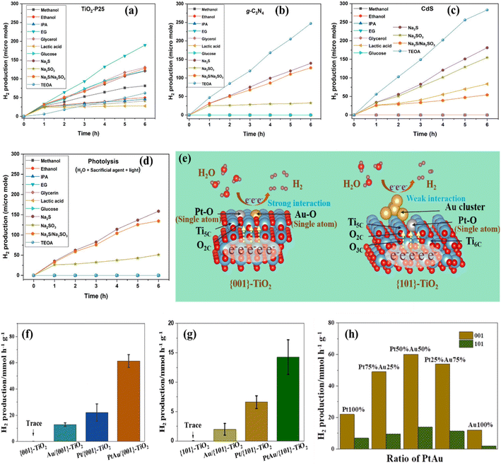 |
| | Fig. 11 (a–d) PWS using different photocatalysts having multiple sacrificial reagents.268 (e–h) {001}- and {101}-faceted TiO2 and PWS performance of Pt–Au/{001}-TiO2 under light illumination. Adapted from ref. 279. Copyright © 2021, American Chemical Society. | |
During the conversion process, when methanol is employed as an electron donor, H2 is generated from water, as described in eqn (7).275–277 Conversely, Guzman and his team276 observed a low rate of H2 production from CH3OH solutions when using a Cu/S–TiO2 catalyst under UV illumination. This observation suggests that, in the presence of a high concentration of water, the reaction between the hole and CH3OH does not take place significantly. On the other hand, the process of oxygen evolution is considerably more challenging from both a thermodynamic and kinetic perspective.
5.6. Dual cocatalyst systems for water splitting
An effective method for achieving PWOS involves the simultaneous addition of dual cocatalysts, which encompass both reduction and oxidation cocatalysts, onto the light-absorbing semiconductor material. This approach proves particularly successful when employed with semiconductors that possess suitable band gaps and energy levels for facilitating the OWS process. The introduction of dual cocatalysts has demonstrated a substantial enhancement in the efficiency of PWOS. For instance, Li and his research team278 observed that combining Zn2GeO4 with noble metals (such as Pt, Pd, Rh, and Au) and metal oxides (such as RuO2 and IrO2) produces a remarkable synergistic effect, significantly boosting the photocatalytic activity during the OWS process. This phenomenon becomes evident when considering the Pt–RuO2/Zn2GeO4 catalyst, which exhibits 2.2 times the photocatalytic activity compared to Pt/Zn2GeO4 and 3.3 times the photocatalytic activity when compared to RuO2/Zn2GeO4. These data strongly suggest that Pt and RuO2 play dual roles in enhancing the POWS. They not only serve as electron and hole traps, facilitating the separation of electron–hole pairs, but they also serve as catalytic sites for the generation of H2 and O2. The incorporation of dual cocatalysts represents a cutting-edge development aimed at significantly enhancing the efficiency of PWOS. Wei et al.279 provided a novel technique for crystalline facet-induced coordinating tuning of Pt–Au dimer co-catalysts. Researchers established that the electrical surroundings of catalysts were extremely facet-dependent by progressively distributing Pt and Au particles over TiO2 catalysts with accessible 001 and 101 sides. Due to the elevated surface energy and unbalanced Ti4+ locations, heteronuclear Pt–Au double ions were fixed on the 001 sides of TiO2via PtO and AuO bonds, whereas the 101 sides remained susceptible to combining with Au ions through loosely bound Au tiny clusters. The maximal H2 generation ratio of the dual-atom co-catalyzed materials was 61.5 mmol h−1 g−1, which was 3 and 5% higher than that of the single-atom equivalents of Pt/TiO2 and Au/TiO2 (Fig. 11e–h).
5.7. Morphology control of photocatalysts
Photocatalysts are divided into four kinds based on their dimensional morphology: first, there are 0D photocatalysts (quantum dots); second, there are 1D nanowires, nanotubes, and nanorods. Third, there is the 2D grouping of nanosheets, followed by the 3D classification of nanoclusters and nanoporous materials.280 In 1995, researchers for the first time confirmed the influence of morphology on catalytic activity of semiconductors. They found that porous TiO2 displayed significantly higher AQE in comparison to bulk TiO2. Since this discovery, scientists have focused on controlling and optimizing the morphology of the photocatalyst to enhance its SA, improve optical absorption, minimize the distance for carrier transport, and increase the exposure of the reaction site.281,282 Modifications in the structure of the catalysts can greatly influence their photocatalytic activity. This has been found in the case of CdS crystal materials, where changes in structural order from nanorods to nanosheets, to irregular nanoparticles, and microspheres show a decline in HER efficiency, as depicted in Fig. 12a.283 This decline is attributed to the inclusion of small CdS nanocrystals within the nanorods and nanosheets, leading to a noticeable quantum confinement effect. In the case of conjugated porous polymers having 2D nanosheet morphology, they have shown a 20 times greater HER than their bulk counterparts.284 Similarly, J. Kosco285 reported that a significant increase in H2 production has been found when organic nanoparticles are synthesized from PTB7-Th (donor polymer) and EH-IDTBR (non-fullerene acceptor) and then put through a structural transformation process including intermixed donor/acceptor blends. These structural changes often lead to increased exposure of the reaction sites and shorter distances for carrier migration. Furthermore, doping oxygen into g-C3N4 nanotubes has proven to be remarkably effective in enhancing HER activity, surpassing the performance of most g-C3N4 nanotubes.286 Similarly, Hu et al.287 and Zhou et al.288 reported that mesoporous configurations and hollow nanotubes or spheres play a crucial role in enhancing light absorption by enabling multiple diffuse reflections during photocatalytic reactions (Fig. 12c and d). Metal–organic frameworks (MOFs) have become widely employed as substrates for advanced catalysts, as depicted in Fig. 12b. It has been found that the pore size of MOFs plays a crucial role in determining the efficiency of photocatalysis.289 Covalent organic frameworks (COFs) based on 3D morphologies have also been proven advantageous when used as a reference for enhancing the composite catalyst structure. Moreover, incorporating 0D quantum dots into organic frameworks is a common practice for improving the absorption of irradiation. The arrangement of Au nanodots within thiol-functionalized UiO66 MOF can influence the migration of charge carriers.290 Finally, a range of 3D structural configurations, such as mesoporous nanospheres, nanoflowers,291 and micro-flowers,292,293 have been designed to attain superior photocatalytic performance.
 |
| | Fig. 12 Morphology control of photocatalysts: (a) schematic of CdS structures with various morphologies (120 °C and 12 h). Adapted from ref. 283. Copyright © 2017, Elsevier, (b) scheme illustrating the fabrication of distinct macro- and meso-porous CDS/UiO-66. Adapted from ref. 289. Copyright © 2021, Elsevier, (c) schematic illustration of the mesoporous TiO2 nanomaterials. Adapted from ref. 287, Copyright © 2016, Royal Society of Chemistry, and (d) schematic illustration of the ordered mesoporous TiO2 nanomaterials. Adapted from ref. 288 Copyright © 2014, American Chemical Society, (e) heterojunctions of liquid phase Z-type, all-solid-state Z-type, and direct Z-type heterojunctions. Adapted from ref. 302, Copyright © 2023, Elsevier. | |
5.8. Construction of heterojunctions
Semiconductor photocatalytic heterojunctions hold the capability of suppressing carrier recombination and, thus, can also boost the separation efficiency of carriers. Heterojunction construction is achieved by embedding different semiconductors to connect their interfaces with face- or point-connections. Such an interface structure provides ease for the transfer and separation of carriers, which is considered vital for enhanced photocatalytic performance. Typically, heterojunctions are categorized based on energy band alignment types, such as straddled, staggered, and broken gaps. Taking into account the case of a straddled gap structure, the occurrence of one semiconductor band is located within the domain of the other. On the other hand, band overlapping does not exist in the broken structure. Only staggering energy band gaps among them achieve the separation of holes from electrons under photoexcitation conditions.294,295 The thermodynamic and kinetic studies have highlighted one of the basic problems existing in the straddled band gap among the two semiconductors, which is the accumulation of carriers at the low position of the CB and the high position in the case of the VB. This gathering of charges leads to a reduction in redox capability, which governs the photocatalytic reaction to the inhibition. Apart from this, the electrostatic repulsive force among the same charges suppresses the migration of carriers. Eventually, these phenomena evolve into challenging problems from the perspective of dynamics and thermodynamics. The Z-type heterojunctions offer efficient carrier separation without compromising the redox capability, as shown in the schematic illustration in Fig. 12e. These are further categorized into three types, Z-type with a liquid-phase, Z-type with an all-solid-state, and construction with a direct Z-type heterojunction. Nevertheless, the utilization of a redox electron–facilitator pair comes with some challenges. One of these is that the working ability of the facilitator-pair is only limited to the selected solution requiring certain pH values. More than that, interference between the optical absorption of semiconductors and the facilitator-pair restricts the extension in the application scale of Z-type heterojunctions with the liquid phase. In discrepancy, these problems are lessened in Z-type with direct heterojunctions296,297 and Z-type with all-solid-state heterojunctions,298,299 placing them in the list of suitable candidates for the industrial application. A photocatalytic heterostructure employing the S-scheme was confirmed to be a novel heterostructure.300 S-scheme heterojunctions have an advantage over conventional heterojunctions due to their unique charge transfer mechanism, which also allows for the preservation of valuable carriers, reorganization of photocarriers through the use of an internally generated electric field, bending of a band, and electrostatic interaction.301 In particular, when a photocatalyst based on a reduced semiconductor comes into contact with a photocatalyst based on an oxidized semiconductor, electrons travel from the reduced semiconductor to the oxidized semiconductor, generating an electric field that bends the bands in the reduced- and oxidized-semiconductors and aligns the fermi levels at the same level.
5.9. Modulation of facets
Another approach to enhance the photocatalytic activity involves facet modulation. It is widely acknowledged that TiO2 nanocrystals with a significant presence of high surface energy facets, such as {001}, {010}, and {111}, can provide a more significant number of active photocatalytic sites.303–305 However, it's important to note that these facets inherently possess thermodynamic instability and tend to diminish rapidly during the crystal formation process to minimize the overall crystal energy. As a result, the most stable {101} aspects have the largest effect on anatase TiO2.231,303 Chang et al.306 used DFT in conjunction with extensive description to clarify the cause of the K-modulated facet and defects in SrTiO3 nanoparticles, which in turn influences the POWS. Researchers discovered that non-equivalent facets were exposed as a result of the variations in binding capacity among K2CO3 and various aspects. Using facet technology, researchers were able to show that the K-loading mechanism involved refilling and replacement processes, with a minimal number of defects at their junction and an optimal bending extent of energy from the surface bands across facets {100} and {110}. In further explanation, the crystalline structure of seeding and the degree of development of various crystallography facets are being identified as critical elements influencing the ultimate form of the resulting formation of a nanostructure. Using thermodynamics to control the interface energy of various components has proven to be an effective technique to control their rate of growth. The degree of interaction between impurities and metals may modify the sequence of free energy in several aspects, resulting in varying rates of development in solution-phase production. As a result, a more gradual development speed could be advantageous to the accessibility of the relevant aspect. The significant interaction among citrate ions and the {111} facets of Pd, promoted their contact, favoring the production of Pd octahedra. According to structural analysis, the geometry of K-loaded SrTiO3 differs substantially from that of pure STO, displaying 110 facets at the reduced edges and 111 facets at the junction. In a similar manner it was inferred that they were mostly determined by the bonding affinities of K2CO3 to various facets of K loaded SrTiO3. The adsorption energy values of the {100}, {110}, and {111} facets to K2CO3 were subsequently calculated using DFT to establish the bonding capacity, as shown in Fig. 13a. The total adsorption values were 0.8299 eV, 0.5538 eV, and 0.0475 eV, correlating to the {110}, {111}, and {100} facets, correspondingly. This finding revealed that K2CO3 was simpler to adsorb onto {110} facets, indicating that its bonding intensity was higher. Furthermore, Fig. 13b shows the basic band schematics at the boundary connecting the {100} and {110} facets of an individual K loaded SrTiO3 particle. In this case, the computed Fermi energy matched the highest point of the CB under realistic conditions. Similarly, Liu et al.307 conducted a comparative analysis of TiO2 nanocrystals that featured {101}, {100}, and {001} facets in terms of their ability to generate H2. Such experiments were performed using a methanol solution with a concentration of 20% V/V under the irradiation of a 300 W Hg lamp with a wavelength of approximately 365 nm. Their findings demonstrated that the {100} and {001} facets displayed significantly higher rates of H2 evolution in comparison to the {101} equilibrium facet.
 |
| | Fig. 13 (a) The adsorption energies of various SrTiO3 crystalline facets to K2CO3; (b) work function values of {110} and {100} facets for K loaded SrTiO3 at the work function variations, and conceptual band illustrations throughout the boundaries among the {110} and {100} facets of an exposed single K loaded SrTiO3 catalyst. Adapted from ref. 306. Copyright © 2022, Elsevier. | |
6. Materials for photocatalysis
6.1. Description and material design
As mentioned earlier, an ideal photocatalyst should have a band gap of at least 1.23 eV and resist photo corrosion. To regulate photogenerated electrons and holes, excellent crystallinity and small particle size are necessary. The WS level has employed a variety of metal oxides, sulfides, nitrides, and phosphates. The catalysts for PWS can be developed utilizing Group I and II metals, as well as lanthanides. A range of semiconductor band structures suitable for WS are displayed in Fig. 14a. Co-catalysts such as Pt RuO2, Au, and NiO can be used to improve the HER, while transition metal cations such as V5+, Ni2+, and Cr3+ can increase photocatalytic efficiency and sensitivity to visible light.
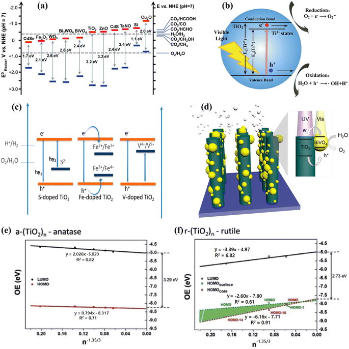 |
| | Fig. 14 (a) Illustration of several semiconductor band structures for water-splitting redox potentials. Adapted from ref. 328. Copyright © 2016, Royal Society of Chemistry, (b) TiO2 band gap diagram. Influence of doping on photocatalytic properties of the TiO2 catalyst. Adapted from ref. 329. Copyright © 2014, Royal Society of Chemistry, (c) schematic representation of the band gap alignment of S, Fe, and V doped TiO2. Adapted from ref. 330. Copyright © 2015, Royal Society of Chemistry, (d) band gap alignment of the TiO2/BiVO4 heterojunction. Adapted from ref. 321. Copyright © 2016, American Chemical Society. (e and f) The calculated HOMO and LUMO energies for anatase TiO2 nanomaterials and the rutile TiO2 nanomaterials as a consequence of n−1.35/3. Adapted from ref. 326. Copyright © 2017, American Chemical Society. | |
6.2. Titanium dioxide (TiO2)
Fujishima and Honda29 demonstrated that TiO2 is an effective photoanode for POWS driven by UV light. TiO2 has received a lot of attention as a photocatalyst because of its chemical stability, low cost, and eco-friendliness, as well as its adjustable energy band gap.308,309Fig. 14b shows the band gap of TiO2. However, TiO2 has two significant drawbacks: it suffers from rapid recombination of charge carriers, which consumes energy, and it cannot use visible light.310 TiO2 only requires UV light to achieve its 3.0–3.2 eV band gap, which represents less than 5% of the solar spectrum.311 These processes are examined in extensive detail. Similarly, modifications including doping, heterojunction formation with metals or other semiconductors, and structural modification are needed to allow visible light harvesting without the recombination of photogenerated electron–hole pairs. TiO2 can be doped with various elements to minimize charge recombination and modify its optical properties.312 Metals and non-metallic elements such as F, B, S, C, and N, have been extensively studied for this purpose.313,314 Luo and coworkers315 synthesized Br and Cl-doped TiO2 using titanium chloride and hydrobromic acid as a source. The band gap of Br and Cl-doped TiO2 was reduced due to the presence of non-metal dopants, resulting in better solar light-induced WS. According to Faria et al.316 doping TiO2 with carbon-based compounds also increases its photocatalytic activity to visible light. Three potential pathways exist for the synergistic action of carbon on TiO2; however they are still not completely explored. In order to inhibit recombination and constrain the aggregation of TiO2 nanoparticles, carbon can function as an electron sink or a photosensitizer.317 Electrons may be able to penetrate the CB of TiO2 by the second process, which involves carbon acting as a photosensitizer. Additionally, carbon can prevent TiO2 nanoparticles from accumulating.318 It is also possible to develop a new optical absorption edge and decrease the energy barrier through the addition of metallic dopants into the TiO2 band gap.319,320 For instance, Fe-doped TiO2 exhibits improved PWS activity. The heterojunctions between semiconductors can limit charge recombination by generating electron–hole pairs with a long lifetime.314 Proper band alignment promotes charge transfer across semiconductors. Fig. 14c depicts the band alignment of doped TiO2 semiconductors. Resasco et al.321 suggested a TiO2/BiVO4 host-guest photoanode system. The system exhibited better performances than BiVO4 or TiO2 alone, owing to the high electron affinity of the photo-anode heterojunction (Fig. 14d). TiO2 can efficiently oxidize or reduce water using a sacrificial agent. In the presence of TiO2, lower oxidation potential reagents such as ethylene, ethanol, methanol, and glycol are commonly employed to reduce electron–hole pair recombination.322 Charge separation and reduced recombination occur when the band gaps of two semiconductors are matched. In this scenario, one semiconductor possesses a higher valence band (VB) energy compared to the other, while its conduction band (CB) energy is lower.323 In metal semiconductors, co-catalysts such as Au, Pt, Pd, and Ru function as electron sinks. Au has a high affinity for photogenerated electrons, low-side reaction activity, and surface plasmon resonance.324,325 Ko et al.326 employed a Wulff-construction technique to synthesize a range of anatase and rutile TiO2 nanomaterials (ranging in size). The HUMO and LUMO energies of TiO2 materials were determined using size-dependent energy balance scaling. The results were subsequently displayed as an estimate of n−1.35/3, where n is the total amount of TiO2 units, as illustrated in Fig. 14e and f. Wu et al.327 investigated anisotropic TiO2 growth on Au nanorods and discovered an electron surface plasmon resonance between TiO2 and Au. Optimizing the structure could boost the HER under visible light.
6.3. Metal oxides
Owing to the aqueous solution stability and inexpensive cost, additional common metal oxides such as Ga2O3, Al2O3, ZrO2, CoO, Fe2O3, Cu2O, WO3, ZnO, and Ta2O5 have also been extensively explored. However, the bulk of metal oxides have significant band gaps that prevent them from absorbing visible light. The VB and CB of metal oxide are generally O 2p and metals. As a result, materials with a high degree of ionic bonding have broad band gaps, such as ZnO (3.4 eV),331 Fe2O3 (2.0 eV)332–335 and Co3O4 (1.3 eV).332 Two transition metal cations with dn electronic configurations Fe2+ and Co2+ can assist in resolving this issue.336 However, these cations have low polarized driven conductance and high resistivity, implying that effective charge carrier transmission is limited.337 Ternary metal oxides such as Bi20TiO32 field,338 SnNb2O6 field,339 and BiVO4 field,332,340 have been investigated to address these challenges and have been explored for their water redox potential due to their narrow band gap (2.4–2.5 eV) and excellent band edge alignment, making them a promising candidate (Fig. 15a). Additionally, BiVO4 exhibits both n- and p-type semiconducting characteristics and high photon to current conversion efficiencies (more than 40%).341 Mishra et al.342 reported that Fe2O3 photocatalysts have a band gap of 2.2 eV, which enhances photon absorption upon visible light. However, the use of Fe2O3 has been limited due to significant bulk recombination. Haghighat et al.343 explored electron transport in iron oxide photocatalysts with variable pH and potential space. Morales-Guio et al.344 synthesized an optically transparent photocatalyst for the OER process using amorphous iron–nickel oxide (FeNiOx). Researchers obtained strong activity at a low overpotential, STH conversion efficiencies more than 1.9%, and “100% faradaic” conversion in unsupported WS with low FeNiOx loading. WO3 has been proposed as an ideal photoanode material due to its good valence band position, which results in a larger onset potential for water oxidation than Fe2O3.345 Amer et al.346 demonstrated the alteration of ZrO2 by depositing thin ZrN coatings on ZrO2 nanotubes to form core–shell structures for visible-light-activated photoanodes. Similarly, Moniz et al.9 observed that anodic photo-corrosion is a significant drawback of WO3. These low-Eg values materials (Fe2O3 and WO3) can be modified by coupling metal cations or generating heterojunction structures with other semiconductors.319 G. S. Costa et al.347 described using a WO3/Fe2O3 photoanode for water oxidation, owing to the significant band gap alignment between WO3 and Fe2O3. They employed the host scaffold WO3 to support a thin layer of Fe2O3 on a WO3 substrate, enabling rapid electron transport across host/guest interfaces (Fig. 15b). They found that increasing the surface area and photon absorption efficiency of Fe2O3 increased water oxidation activity. Cobalt oxide (CoO) has been identified as a photocatalyst for H2 evolution.348,349 Liao et al.348 demonstrated that CoO nanocrystals can be a photocatalyst for visible-light-induced WS. However, the limited lifetime and rapid deactivation of CoO nanoparticles prevent their application as a HER photocatalyst.
 |
| | Fig. 15 (a) Preparation and characterization of a triple-layer planar heterojunction (TPH) photoanode composed of BiVO4/WO3/SnO2, (1) sol–gel deposition technique. (2) XRD pattern of TPH photoanodes. (3) SEM picture of the improved TPH photoanode in cross-section, demonstrating close contact between layers without any voids. (4) Alignment of the SnO2, WO3, and BiVO4 films along with their bands. Adapted from ref. 350. Copyright © 2016, American Chemical Society, (b) cyclic voltammograms (20 mV s−1) for the FTO/WO3/Fe2O3 electrode in the dark, in 0.1 mol L−1 Na2SO4 aqueous solution, and in supporting electrolytes containing varying concentrations of RhB dye (CV under irradiation in 5.0 106 mol L−1 RhB dye solution) with the UV-vis RhB absorption spectrum (inset) for comparison. Adapted from ref. 347. Copyright © 2020, Springer Nature. | |
6.4. Metal sulfides
For decades, CdS and ZnS metal sulfide catalysts have gained the most attention.351 CdS is a potential photocatalyst for visible light WS because it has a lower band gap (2.4 eV) than metal oxide semiconductors.113 However, bare semiconductors have poor H2 generation rates due to quick photogenerated electron and hole recombination and thus are susceptible to corrosion under light irradiation.323 To overcome this issue, other noble metals can be utilized as co-catalysts.352 Huang et al.353 generated a hollow bimetallic sulfide material with a narrow band gap by transferring electrons to the noble metal electronic level or shifting them between the CB of semiconductors. When sensitized with EosinY dye or TiO2 and g-C3N4 semiconductors, it generates the HER at a rate equivalent to platinum. CdS has also been shown to enhance semiconductor activity when used in conjunction with TiO2 and g-C3N4 (ref. 354) as TiO2 (3.3 eV) exhibits a lower response to visible light than CdS (Fig. 16a).355 The photoactivity of ZnS for the HER has been increased. Li et al.356 reported using the solid solution systems of Zn1−xCdxS to generate the HER under visible light. The band gaps of solid solution photocatalysts can be easily modified by altering the molar ratio of Zn/Cd. Because of the lower band gaps of solid solution photocatalysts, bare ZnS photons absorb more effectively under visible light.357 Furthermore, earlier research has suggested that coupling CdS with large band gap metal oxides such as TaON, TiO2, and ZnO might increase the stability of composite materials.358,359 Through minimizing charge recombination, various carbon nanostructures may be coupled with CdS to increase WS performance. Any interaction with carbon nanostructures can dramatically increase charge separation due to solid conductivity of CdS. According to the increased catalytic characteristics of nanocomposites, several approaches for developing carbon-based CdS have been investigated, ranging from simple integration of the two components to in situ synthesis on the surface of graphene oxide utilizing oxygen molecules as a template.360 WS2–Au–CuInS2 has been generated for photocatalytic HER performance by sandwiching gold nanoparticles between WS2 nanotubes and CuInS2 (CIS) nanoparticles.361 The incorporation of Au nanoparticles substantially enhanced visible light absorption. Because of the LSPR impact of Au nanoparticles and the quicker photogenerated carrier separation from Type II band structures, WS2–Au–CIS shows the greatest HER performance (Fig. 16b).
 |
| | Fig. 16 (a) The possible photocatalytic mechanism of TiO2/CdS mesoporous microspheres. Adapted from ref. 355. Copyright © 2014, S. Yu et al., (b) (1) the H2 production plot of WS2–Au–CIS is shown in the inset. (2) A rough mechanism plan. Adapted from ref. 361. Copyright © 2015, AIP Publishing LLC. (c) (1) The scheme of the photo response is measured using a single Ta3N5 nanobelt FET. (2) The I–V characteristics of the FET when used as a photodetector at different light wavelengths and in the dark. (3) Transient response of Ta3N5 nanobelts. (4) The photoreaction of Ta3N5 nanobelts irradiated with a 450 nm light pulse at different vacuum and atmospheric pressures, split at a frequency of 100 Hz. Adapted from ref. 377, (d) (1) recycling of a CR; (2) MG using WO3 and WO3/g-C3N4 catalysts; (3) photocatalytic mechanism of WO3/g-C3N4 catalysts under visible light irradiation. Adapted from ref. 376. Copyright © 2019, Springer Nature. | |
6.5. Nitrides
Photocatalysts such as nitrides and oxynitrides can be used to achieve efficient solar light harvesting for WS.362 The energy of the nitrogen 2p orbitals in nitrides is higher than the energy of the oxygen 2p orbitals in metal oxides thus making it easier to excite electrons to the CB in nitrides.363 Water oxidation is a process that requires a high energy input, and a solid solution of GaN and ZnO has been proposed as a photocatalyst. Both materials have high band gaps and are poorly visible light absorbers. However, after mixing the two materials, new electronic states develop that significantly lower the band gap in a Ga1−xZnx and N1−xOx solution.364 Perovskite-like combined oxides of NaTaO3 and SrTiO3 are known for their excellent WS performance (Fig. 16c).365 A substitution of one nitrogen atom for an oxygen atom in this compound causes the absorption edge to move toward longer wavelengths (600 nm), which boosts photocatalytic activity. Ta3N5 has also been shown to be an effective photocatalyst for WS. Zhen et al.366 in 2013 synthesized template-free Ta3N5 nanorods doped with Co(OH)x and used them as an anode in a PEC WS. Alternatively, Ta3N5 has been partially replaced with Mg2+ and Zr4+ ions to lower the onset potential of PEC water oxidation.367 It is possible to enhance the photocatalytic activity of other semiconductors by similarly modifying their composition. g-C3N4 has been utilized as a photocatalyst for the HER due to its low band gap of 2.7 eV. A sacrificial agent (oxidizing agent) in combination with g-C3N4 could generate H2 from water at visible light wavelengths without using a noble metal (540 nm). However, bare g-C3N4 is not an efficient photocatalyst. Wang et al.368 developed g-C3N4 from cyanamide, which exhibited a visible light absorption edge and continuous stable HER performance over 75 hours. Doping g-C3N4 with non-metal (S, F, B, and P) and metal (Pt, Pd, Fe, Zn, and Cu) atoms has enhanced the photocatalytic activity.369–374 Additionally, graphene, carbon nanotubes, and reduced graphene oxide can also be utilized to enhance charge separation in g-C3N4.272,375 Furthermore, Sumathi et al.376 reported that WO3/g-C3N4 heterostructure catalysts synthesized using a one-step microwave irradiation approach exhibited significant visible-light-driven photocatalytic activity (Fig. 16d). g-C3N4 is a versatile photocatalyst that can be used in both PEC cells and solar systems.
6.6. MXene nanosheets
Recently extensive concerns have been raised about the emerging 2D layered transition metal carbides/carbonitrides/nitrides. The first synthesis of transition metal carbides, such as Ti3C2, was reported by Gogotsi et al.378 in 2011. The yield of the light-driven HER is limited because photoinduced carriers rush to recombine. MXenes,157 g-C3N4,379 and reduced graphene oxide380 adaptation are often seen as guest materials to boost the performance of heterogeneous photocatalysts because of their outstanding capability of transferring electrons.157,380,381 When MXenes come into contact with other photocatalysts, features including their high SA, many active adsorption sites, and excellent 2D structure help enhance photocatalysis. As seen in the instance of 0D nanomaterial/2D MXene, high metal conductivity is also necessary for stimulating the photocatalytic activity. Additionally, intimate contact enhances physical contact and provides carriers with the possibility to transition from the 0D (functioning as a host) to the 2D MXene interface.157,382 T. Su et al.157 analyzed mono- and multi-layer structures of Ti3C2TX as cocatalysts for TiO2. The H2 production for the case of a monolayered Ti3C2TX/TiO2 hybrid (abbreviated as 5-TC-TO) structure was 2.6 mmol h−1 g−1, compared to multilayered Ti3C2TX/TiO2 (5-MT/TO). It is linked to increased SA in comparison to multi-layered co-catalysts and the occurrence of monolayer Ti3C2TX/TiO2 active sites. Shortening of distance in the case of the monolayer Ti3C2TX is feasible for the rapid migration of photogenerated carriers through the CB of TiO2 to Ti3C2TX. Generated holes in the VB through this process are utilized by the hole scavenger. Consequently, a reaction that would lead the H+ ions to H2 would be accomplished more easily to effectively utilize the photogenerated charges gathered at the Ti3C2TX.
Cui et al.,383 outlined the method of transforming Ti3C2 MXene into 3D permeable structures of Ti3C2–TiO2 nanoflowers. These structures exhibit highly efficient catalysts for the OER, remarkable performance and extended sustainability across a broad range. Notably, the catalysts demonstrated impressive efficiency without requiring the incorporation of any noble metal co-catalyst or sacrificial reagents. The Ti3C2–TiO2 nanoflowers have been designed by oxidizing and alkalinizing HF-etched Ti3C2 MXene simultaneously, subsequently undergoing ion exchange reactions and annealing procedures (Fig. 17a). Moreover, MXene is a recently developed intermediate for oxide, and in the primarily oxidative Ti3C2 MXene, the oxide (TiO2) is closely related to the Ti3C2 MXene component. In this arrangement, the Ti3C2 MXene serves as a direct titanium supplier or an interface for transporting photoinduced electrons to improve charging separation performance. Schottky intersections generated by interface contact among Ti3C2 MXene and TiO2 also dramatically speed up the photoexcited separation of charges, whereas TiO2 absorbs light and supplies electrons as well as holes. Additionally, the nanoflower-like arrangement with 3D porosity can improve photocollection, limit the propagation pathways for photogenerated holes and electrons, increase surface area, and enable the solvent to reach the reactivity areas. In spite of the lack of precious metals (Pt, Au, Ru2O, etc.), such distinctive characteristics associated with developed Ti3C2–TiO2 nanoflowers result in substantially improved WS performance for the simultaneous development of H2 and O2 sources in a stoichiometric proportion of 2:1, without any sacrificial materials (Fig. 17b–g).
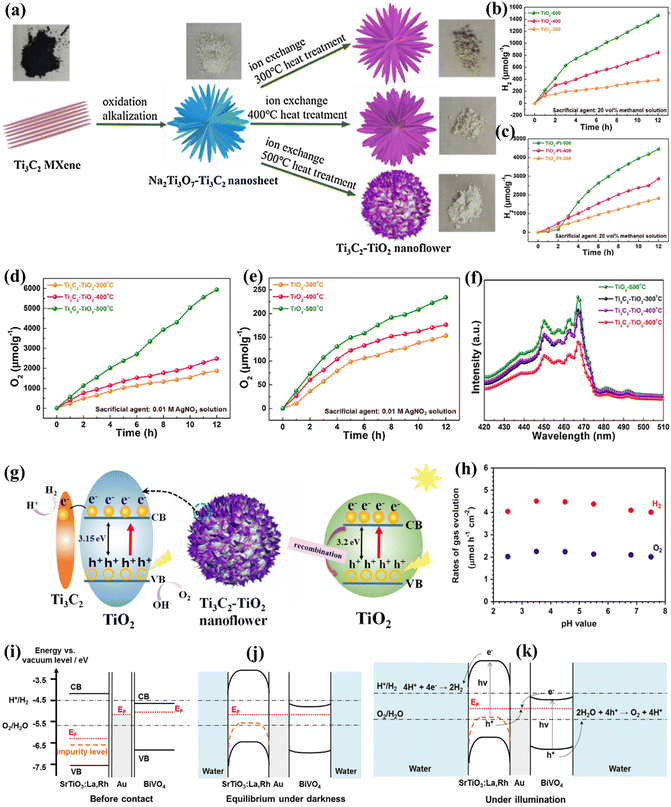 |
| | Fig. 17 (a) Diagram showing the steps involved in generating Ti3C2–TiO2 nanoflowers, (b and c) HER performance with the existence and without the existence of a co-catalyst using Ti3C2–TiO2 nanoflowers fabricated by distinct calcinations, (d) OER performance of Ti3C2–TiO2 nanoflowers and (e) TiO2 nanobelts fabricated by varied calcinations without a co-catalyst along with (f) DRS of the as-prepared materials, and (g) graphical photocatalytic process for TiO2 nanobelts and Ti3C2–TiO2 nanoflowers under solar irradiation. Adapted from ref. 383. Copyright © 2018, Elsevier, (h) the photocatalytic efficiency of a SrTiO3:La, Rh/Au/BiVO4 plate is pH dependent. Charge distributions of SrTiO3:La, Rh/Au/BiVO4 structures (i) before interaction, (j) in the dark during optimum situations, and (k) during band gap stimulation. Adapted from ref. 385. Copyright © 2015, Elsevier. | |
6.7. Photocatalytic overall water splitting with immobilized particulate systems
Up until late, using particle suspension systems in laboratories has been the standard method for generating photocatalytic one-step excitation, or Z-scheme OWS. However, the scalability of such WS methods is notably constrained, presenting challenges when attempting to expand particle suspension processes for industrial-scale production. For instance, dispersing a significant amount of particulate photocatalysts within a substantial quantity of water before exposing it to sunlight requires a considerable power supply. One of the obstacles associated with sustaining is getting the photocatalyst powder out of suspension and gathering it. However, a suspension-type reactor cannot monitor the movements of the sun to effectively harvest solar energy. Immobilizing photocatalyst powders on a particular substrate is therefore necessary to enable the upscaling of WS systems from laboratory to industrial scales. However, when compared to particle suspension systems, the insufficient diffusion of water to photocatalyst particles and the slow release of gaseous products from the accumulated particle layer present difficulties, often leading to a reduction in photocatalyst performance within fixed particulate systems. As a result, a detailed evaluation of immobilized photocatalyst systems is required for future developments in order to identify any potential problems related to their practical deployment. The primary endeavor to address particulate photocatalysts for OWS through one-step excitation involved the fabrication of a particulate array utilizing the widely recognized GaN:ZnO photocatalyst.384 A combination of GaN:ZnO photocatalysts modified with Rh2xCrxO3 and micrometer-sized silica particles was applied onto a 5 × 5 cm glass plate using a drop-casting method. As a result, the photocatalysts fixed to the panel displayed WS activity comparable to that generated through a suspension. The inclusion of silica particles proved to be a crucial factor in enhancing the performance of the photocatalyst panel. This effect is caused by the hydrophilic activity of silica, which causes gaps to form between the photocatalyst particles. This permits water to reach all areas of the photocatalyst and also provides for the efficient release of developed gases. To evaluate the potential of this method, a 1–1 m panel was prepared using the same approach, employing a RhCrOx-modified Al-doped SrTiO3 particulate photocatalyst. This panel served as a test module for OWS on a square-meter scale.93 Domen et al.385 currently showed that catalyst materials embedded on metallic layers via particulate transport move due to the exclusive mechanical and electrical interactions that exist between the particles of semiconductors and the metallic layers, resulting in reduced resistance and increased photocurrent in the photoelectrochemical WS response. Based on these findings, it is anticipated that linking the HEP and OEP with metal conductive surfaces via the particulate transport technique will offer a successful way of boosting electron transmission performance and thereby increasing WS performance. Researchers present an all-solid-state system for oxidative mediator-free Z-scheme WS, composed of a plate made of HEP and OEP nanoparticles and a layer of conductivity for effective electron transmission. Using SrTiO3:La, Rh, and BiVO4 as a model, this work explores the efficacy and benefits of all-solid-state design of structures over typical Z-scheme devices using interparticle interaction of electrons for the OWS process (Fig. 17h–k). Unfortunately, the presence of H2 and O2 in the reactor poses an obstruction to water diffusion and, in turn, leads to a significant risk of explosion. It is noteworthy that as the WS efficiency reaches a specific threshold, there arises a potential for explosive mixtures of H2 and O2 within the panel reactor and it becomes necessary to separate these gases. Nevertheless, a panel-type reactor that integrates a particulate photocatalyst for one-step excitation of OWS has demonstrated promising suitability for large-scale solar H2 production.
6.8. Metal–organic frameworks (MOFs)
Several advanced catalysts for H2 generation processes have been developed by researchers, with MOF-based catalysts being one of the foremost potential materials.386 MOFs are assembled from metallic ions and organic compounds, have gained prominence owing to their distinctive porous adaptable framework and large surface area, and are extensively employed in a variety of fields including gas absorption and separation, catalytic processes, energy conservation, and many more. Organic compounds in the molecular framework of MOF-based nanomaterials may act as signals to absorb radiation, be stimulated, and yield hole and electron couples.387 Electrons may go from ligands to metallic complexes and interact with the H+, resulting in the photocatalytic HER. Certain metallic sulfides or metallic oxides, including MoS2, CdS, and TiO2 NPs, are additionally frequently employed to increase the photocatalytic performance of MOF-based photocatalysts. Ma et al.388 modified zeolitic imidazolate framework (ZIF)-67 treated with carbon nitride with MoS2 NPs. Researchers demonstrated that the incorporation of MoS2 may extend its visible-light absorption capacity and increase the distinction capacity of photoinduced electrons/holes via a variety of photoelectric experiments. Furthermore, Pan and colleagues389 synthesized ZIF-8 on titanium dioxide-based hollowed nanospheres (TiO2 HNPs) using a simple sonochemical method. The effective charge dissociation capability of ZIF-8, as verified through the analysis of photoluminescence (PL), time-resolved photoluminescence (TRPL) decay transient spectra, electrochemical impedance spectra (EIS), and photocurrent (PC) reaction, allows for easy infusion of particles from ZIF-8 to TiO2 HNPs. This is facilitated by the presence of influential prominent areas offered by ZIF-8. As a result, the catalyst exhibited outstanding ability to yield, with an AQY of up to 50.89% using simulating visible light conditions (Fig. 18a–c). Later, Chen and colleagues390 developed a range of crown-shaped Zn0.5Cd0.5S MTiO2 hybrids that originated from MOFs. The ideal quantity of the Zn0.5Cd0.5S MTiO2 hybrid has a higher AQY of 48.9% at 420 nm contrasting to pristine Zn0.5Cd0.5S or M-TiO2. Additionally, the HER could exceed 180.4 mmol g−1 h−1. The significant increase in the photocatalytic function may be attributed mostly to the increased surface area, greater exposure to functional areas, and improved performance in separating electrons and holes (Fig. 18d and e). Similarly, Liu et al.391 presented a new form of nickel-based MOF singled crystalline material, named Ni-TBAPy-SC, together with its exfoliating nanobelts, referred to as Ni-TBAPy-NB. These materials exhibit excellent stability over a broad spectrum of pH levels in aqueous solutions. Analytical and computational findings suggest that electron transmission from the H4TBAPy compound (light gathering core) to the Ni–O clustering nodes (catalytic core) is possible. This electron transmission may effectively promote WS for producing the HER without the need for a cocatalyst. Exfoliating 2D nanobelts exhibit superior charging isolation as opposed to the individual crystallite. This is due to their reduced charge transmission range and significantly increased reactive surface areas. Therefore, the nanobelts demonstrate a 164-fold increase in water-reducing performance.
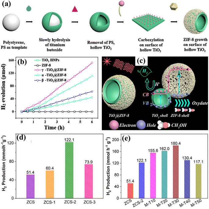 |
| | Fig. 18 (a) Diagram showing the incorporation of double-shell TiO2/ZIF-8 hollow nanoparticles. (b) The photocatalytic ability for generating the HER of TiO2 HNPs, ZIF-8, and α-/β-/γ-TiO2/ZIF-8. (c) The operation of the HER over TiO2/ZIF-8. Adapted from ref. 389. Copyright © 2019, Elsevier, (d) HER of ZCS composites. (e) ZCS-2, M-TiO2, and varied proportions of ZCS-2/M-TiO2 mixtures. Adapted from ref. 390. Copyright © 2021, Elsevier. | |
6.9. Covalent organic frameworks (COFs)
COFs structurally associated with organic constituent blocks have a high area of surface, an adaptable framework, and high durability.392 COF elements exhibit distinct asymmetries and associations in the context of the photocatalytic HER, as contrasted with MOFs. COFs are a kind of crystallized porous material which are composed of less compact components (including O, C, B, and N) connected by significant covalent bonding.393 They have a large surface area and may have various shapes based on the functionalities that constitute their organic linkages. Furthermore, the presence of a covalent connection in the COF framework significantly improves its durability. Consequently, it is challenging to transform highly covalently linked COFs into large-scale crystalline materials, leading to a constrained number of regular structural components.394 The use of solar radiation to facilitate the conversion of water into H2 and O2 has been widely recognized as an extremely potential technique to produce environmentally friendly H2. The processing of photons into chemical energy necessitates the employing of catalysts that possess an appropriate bond arrangement to provide enough reaction possibility.395 Additionally, these photocatalysts must exhibit excellent charge dissociation capability to sustain a constant supply of electrons to the reducing region. COFs possess unique attributes that enable them to fulfill these demands. Multiple studies are being conducted on catalysts based on COFs for the purpose of H2/O2 evolution.396–398 These studies include the development and regulation of the organic framework. Incorporating electron donor/acceptor ligands with COFs is a useful method for enhancing charge isolation and transmission in COFs.399 Wang et al.400 transformed a N-acylhydrazone interlinked COF (H-COF) into a durable π-conjugated oxadiazole connected COF (ODA-COF) by performing post-oxidative cyclization of hydrazone coupling. This process resulted in very effective photocatalytic HER, as shown in Fig. 19a and b. The post-synthetic alteration not only increased the spread of π-electrons in the structure, but also enhanced the chemical durability of COFs. This effectively inhibited charging replication and enabled the movement of electrons. When a Pt cocatalyst was used, the ODA-COF material achieved a HER of 2615 μmol g−1 h−1, that is more than four-fold the performance seen for the H-COF material connected via N-acylhydrazone. Furthermore, Yang et al.401 described the synthesis of a 2D bipyridine-based COF (Bp-COF) that demonstrated the photocatalytic OER. This study constituted the initial instance of imine-interlinked COFs successfully achieving the OER using visible illumination. Bp-COF was developed by reacting 2,20-bipyridine-5,50-dicarboxaldehyde with 1,3,5-tris(4-aminophenyl)benzene by a chemical process known as Schiff base condensation (Fig. 19c). The feasibility of combining the water oxidation and proton reducing processes in Bp-COF was proven by computational and analytical analysis of its band configuration. In this study, cobalt atoms were incorporated into Bp-COF and bound to the bipyridine patterns to function as the co-catalyst for the photocatalytic OER. When the BpCoCOF-1 material was loaded with 1 wt% Co, it showed a larger HOMO intensity as opposed to the pure Bp-COF material. This increased HOMO intensity may lead to a greater oxidation possibility of the OER, as seen in Fig. 19d. BpCo-COF-1 achieved an outstanding OER of 152 μmol g−1 h−1, as shown in Fig. 19e. The isotopic labelling studies provided additional confirmation that the identified gas originated from the division of water, rather than the degradation of the catalyst. The catalyst demonstrated its durability in a continuous OER performance study extending over 31 hours.
 |
| | Fig. 19 (a and b) The process for the fabrication and photocatalytic HER of H-COF and ODA-COF. Adapted from ref. 400. Copyright © 2022, John Wiley & Sons, (c) Graphical depiction of the fabrication of Bp-COF, (d) the estimated HOMO/LUMO spectral positions and (e) the photocatalytic OER performance of Bp-COF and BpCo-COF-1. Adapted from ref. 401. Copyright © 2020, Elsevier. | |
6.10. Layered double hydroxide (LDH)
LDH-based materials have recently garnered interest due to their distinctive 2D frameworks and the ability to modify their arrangements, as well as their appealing photonic and electrochemical characteristics.402,403 These components possess an excellent capacity to adsorb substances and can adjust their band gap. They are good for exchanging cations and anions and can develop distinct locations for oxidation/reduction processes. This allows for the efficient synthesis of H2/O2via the process of WS.404 Furthermore, the stacked composition of LDH components enables the incorporation of crystals with diverse dimensions, shapes, and morphologies, in addition to different kinds of anions and cations that constitute its constitution. These attributes significantly influence the effectiveness of transferring charges and separating, ultimately determining the total efficacy of photocatalytic energy transformation.405 Multiple studies have been published to include various facets of LDH fabrication, alterations, and uses. A prime instance may be seen in the research of Fan et al.,406 which specifically examines the techniques used for developing adaptive LDHs and their subsequent usage as heterogeneous catalysis. In 2016, Mohapatra et al.404 extensively reviewed 164 references that focused on advancements in the synthesis of LDHs and their use in photocatalytic processes such as photodegradation of dyes, photocatalytic HER, and photoreduction of CO2 source. In the preceding decade, Yang et al.407 conducted a comprehensive analysis of the complicated elements that impact the absorbing and the degradation mechanisms of pollutants when LDH nanomaterials are used. In 2018, Wu et al.408 discussed the progress achieved in developing heterojunctions using LDH. They specifically focused on the assembly methodologies and the building processes involved in this technique. Megala et al.409 developed a 2D/2D heterostructure of NiAl-LDH/g-C3N4 composites using the in situ hydrothermal technique. Researchers subsequently evaluated the photocatalytic efficiency of these composites for H2 production by WS under simulating light radiation. The NiAl-LDH/g-C3N4 composites, after optimization, exhibited a HER of 3170 μmol h−1 g−1, which is the most significant observed estimate for the NiAl-LDH group yet. The improved photocatalytic performance is due to the development of a 2D/2D heterostructure in the NiAL-LDH/g-C3N4 composites. This heterostructure allows for effective isolation of electrons/holes when exposed to illumination, resulting in higher electron conductance within the composites (Fig. 20a–c). Similarly, Wang et al.410 developed and assembled a core–shell catalyst consisting of Cu2O/ZnCr-layered dual hydroxide (LDH) to establish a highly efficient light-activated OWS. The Cu2O/ZnCr-LDH catalyst demonstrates excellent performance, achieving a significant efficiency with an HER of 0.90 μmol h−1 and OER of 0.44 μmol h−1 under visible-light irradiation. Notably, this catalyst does not need a sacrificial reagent or co-catalyst, making it one of the most effective documented catalysts under similar circumstances. The Cu2O/ZnCr-LDH heterojunction effectively utilizes the synergy impact of Cu2O and ZnCr-LDH, specifically with regard to aligning their band structures, as shown through empirical and theoretical research. The S2O32− cluster located at the terminal of ZnCr-LDH plays a crucial role by effectively mediating between the two elements. This not only prevents the breakdown of Cu2O under light but also additionally enhances the movement of the photoexcited electrons/holes couple (Fig. 20d and e).
 |
| | Fig. 20 (a–c) The fabrication procedure and photocatalytic HER of the NiAl LDH/g-C3N4 nanocomposite. Adapted from ref. 409. Copyright © 2020, Elsevier, (d and e) graphical depiction of the synthesis and PWOS of Cu2O/ZnCr-LDH hollowed materials. Adapted from ref. 410. Copyright © 2017, Elsevier. | |
6.11. Chalcogenides
Metallic oxides and chalcogenides are extensively studied as semiconductor compounds that exhibit conducting capacities transitional among those of conductors and insulators.411 Chalcogenides are materials that consist of several electropositive components plus a minimum of one chalcogen charge (S2−, Se2−, or Te2−).412 These materials are recognized due to their small band gap values. These materials are still being studied because of their many desired characteristics, such as a small difference in energy between the highest and lowest energy levels, minimal levels of toxic effects, ability to interact well with living organisms, affordable price, and easy production.413 The deployment of chalcogenide based photocatalysts in photocatalytic functions has been extensively determined, mostly due to their small band gap energy, which allows for effective absorption of visible radiation.414 In more detail, the study of Zhu et al.415 used computational methods employing DFT to demonstrate that single layers of 2D silicon chalcogenides (SiX, where X = S, Se, Te) had band gap values ranging from 2.43 to 3.00 eV. These materials, which are semiconductors, also possess advantageous band edge locations that make them suitable for PWS. Optical computations indicate that SiX single layers exhibit significant optical absorbance in the visible-light range. Additionally, the bandgap and band junctions of single layers of silicon chalcogenides may be adjusted by introducing biaxial stress or extending the quantity of the layers, allowing them to better correspond to the reactive potentials of water. The 2D SiX exhibits a combination of electrical characteristics, significant carrier accessibility, and optical characteristics, making it a very potential catalyst for WS. Liu et al.416 presented the surface phosphorization of CZS nanotwins, which exhibit significant erosion strength for photocatalytic WS. This process enables simultaneous synthesis of H2 and H2O2 without the need for any co-catalyst or sacrificial reagent. The effectiveness of the process relies on the integrated impact of coherence dual surfaces inside the main compound, which facilitates effective separation of charges, interface P bridging that enables fast charging movement, and the presence of red phosphorus (RP) on the outermost layer as potential areas for H2O2 formation. The process included two main phases that produced surface phosphatized CZS nanotwin materials. First, CZS nanotwins were synthesized using a hydrothermal approach. Subsequently the nanotwins were phosphorized by subjecting them to combustion of NaH2PO2·H2O, as illustrated in Fig. 21a and b. Adding NaOH during the hydrothermal procedure will cause the metallic ions to precipitate earlier. Under these circumstances, the degree to which the metallic ions are released and sulfurized would decrease, hence facilitating the development of nanotwins. In the presence of an argon environment, the PH3 gas produced by the thermal decomposition of NaH2PO2·H2O will undergo a reaction with CZS nanotwins, resulting in the formation of a P loaded CZS nanotwin material on the surface. Photocatalytic experiments were then performed to investigate the potential of such materials for WS under visible illumination exposure, with no need for any sacrificial reagent. Fig. 21c demonstrates that the pure CZS nanotwins showed a modest performance of approximately 26.5 μmol h−1 g−1 for the HER from WS. During the phosphating procedure, the HER observed a substantial prominence and achieved its peak activities of 137.2 μmol h−1 g−1 across the CZSP5 material despite the use of any co-catalyst. This activity level is approximately 27-fold higher compared to that of typical CZS-C, as seen in Fig. 21d. The AQY values at various wavelengths are displayed in Fig. 21e. Remarkably, CZS-P5 also exhibited outstanding durability under these reaction conditions. There was no noticeable decrease in the photocatalytic function detected throughout a 15-hour test period (Fig. 21f). The findings of the RRDE investigation are shown in Fig. 21g. The transmitted electron ratio for CZS-P5 nanotwins was shown to be about 2, confirming the occurrence of a two-electron interaction channel in the photocatalytic process of WS, leading to the generation of H2O2. To comprehend the probable process of H2O2 generation, researchers conducted additional investigations on the associated reactive components. The presence of ·OH radicals was identified using a Pl technique that relies on the interaction involving ·OH and terephthalic acid (Fig. 21h). Similarly, the photocatalytic performances of different photocatalysts along with stability depiction are shown in Table 1.
 |
| | Fig. 21 (a and b) Graphical depiction of the fabrication procedure of CZS and CZS-P, (c) photocatalytic HER and H2O2 production from WS using CZS and CZS-P1-10 under visible light illumination, (d) comparison of the photocatalytic performance of all synthesized materials, (e and f) UV-vis AQY and durability assessment of the HER for CZS-P5, and (g) the voltages of the disk electrode (Id) and ring electrode (Ir) are measured to determine the movement of electron rates across CZS-P5. (h) The PL patterns of the effluent including terephthalic acid measured at a steady state after varying illumination durations. Adapted from ref. 416. Copyright © 2021, American Chemical Society. | |
Table 1 The photocatalytic performance of different photocatalysts along with stability depiction
| Photocatalysts |
HER |
OER |
Stability |
References |
| Au–NiOx/TiO2 |
18.3 μmol h−1 g−1 |
9 μmol h−1 g−1 |
Good |
247
|
| NiO–SrTiO3 |
240 μmol h−1 g−1 |
130 μmol h−1 g−1 |
Fair |
417
|
| CaTaO2N |
6.5 μmol h−1 g−1 |
3.2 μmol h−1 g−1 |
Good |
418
|
| Ni/Sr2Nb2O7 |
6.7 μmol h−1 g−1 |
3.3 μmol h−1 g−1 |
Good |
419
|
| Cu2O@ZnCr-LDH |
0.90 μmol h−1 |
0.44 μmol h−1 |
Excellent |
420
|
| Co–Pi/Bi–La2Ti2O7/Pt |
66.6 μmol |
32.1 μmol |
Good |
421
|
| GDY/g-C3N4–VN |
0.48 μmol h−1 |
0.24 μmol h−1 |
Good |
422
|
| Pt/g-C3N4 |
61 μmol h−1 g−1 |
31.5 μmol h−1 g−1 |
Excellent |
184
|
| GaFeO3 |
9.0 μmol h−1 g−1 |
4.5 μmol h−1 g−1 |
Fair |
423
|
| NiO/NaTaO3:La |
5900 μmol h−1 g−1 |
2900 μmol h−1 g−1 |
Fair |
424
|
| Al–CuS/ZIS |
153.6 μmol h−1 g−1 |
73.1 μmol h−1 g−1 |
Good |
425
|
| BiVO4–Ru/SrTiO3:Rh |
40.1 μmol h−1 g−1 |
18.6 μmol h−1 g−1 |
Fair |
96
|
| Pt/KCa2Nb3O10 |
260 μmol h−1 g−1 |
120 μmol h−1 g−1 |
Good |
426
|
| CDots/CoO |
33.4 μmol h−1 g−1 |
18.2 μmol h−1 g−1 |
Good |
427
|
| Pt/CdS@Al2O3 |
62.2 μmol h−1 g−1 |
27.3 μmol h−1 g−1 |
Good |
428
|
| Ba2In2O5/In2O3 |
58.6 μmol h−1 g−1 |
30.4 μmol h−1 g−1 |
Excellent |
429
|
| Cu2O/ZnCr-LDH |
45 μmol h−1 g−1 |
22 μmol h−1 g−1 |
Good |
410
|
| Co1-phosphide/PCN |
410.3 μmol h−1g−1 |
204.6 μmol h−1 g−1 |
Good |
430
|
| Pt-loaded Mg/TiO2 |
850 μmol h−1 g−1 |
425 μmol h−1 g−1 |
Good |
431
|
| Pt/GaN NWs |
29.4 μmol h−1 |
16.4 μmol |
Good |
432
|
| FeCoPi/Bi4NbO8Cl-OVs |
2.5 μmol h−1 |
1.3 μmol h−1 |
Good |
433
|
| RuO2/GaN:ZnO |
3200 μmol h−1 g−1 |
(1500)5 μmol h−1 g−1 |
Fair |
434
|
| CQDs/Ag/Ag3PW12O40 |
8.04 μmol h−1 g−1 |
4.02 μmol h−1 g−1 |
Good |
435
|
| ZnRh2O4/Ag/Bi4V2O11 |
0.25 μmol h−1 g−1 |
0.089 μmol h−1 g−1 |
Good |
436
|
| CoO/g-C3N4 |
50.2 μmol h−1 g−1 |
27.8 μmol h−1 g−1 |
Good |
437
|
7. Photocatalytic water splitting: a theoretical modeling approach
Light absorption,438 electron/hole transport,439 semiconductor band edge alignment,440 and surface photo redox chemistry441 have all been theoretically studied and have predictive capacity, low processing cost, and reproducibility. Density functional theory (DFT) is commonly used to predict and explain the electrical structure of materials due to its excellent accuracy.442 However, a significant disadvantage of DFT is its inability to forecast band gaps due to poor self-interaction and correlation accurately. To address this issue, hybrid functionals or the injection of electron repulsion into a subset of localized orbitals is a practical way.443,444 Although hybrid functions are more accurate than classic exchange and correlation functions for predicting band gaps and locating excited states, they are computationally costly.445,446 The most successful technique for solving the band gap problem is known as many-body perturbation theory (MBPT).447,448 Although this method is computationally costly, it sets a baseline for comparative research, which can aid in the development of new methods.445,449 The most recent approach, TB09, combines the modified exchange capacity of Becke–Johnson with an LDA correlation.450,451 When combined with variants, this strategy has been proven to be one of the most cost-effective approaches to date.445,452 Computational approaches are beneficial for anticipating impurity states produced by doping in photocatalytic systems such as TiO2.453 The bulk of studies rely on cluster-based models rather than time-dependent density functional theory (TD-DFT) as shown in the computational investigation of the photoinduced homolytic dissociation of water in the pyridine–water complex (Fig. 22). In addition to predictions, theoretical and computational techniques may enable us to properly comprehend state features. The investigated topics include the band structures and densities of the BiVO4 state, the electron/hollow production process, and the mobility and energy level of the surface processes. BiVO4 addresses the photoinduced electrons and light on various crystal-like facets. According to computer studies, the (010) facts have a low energy absorption of over 420 nm, a faster transit electron/hole, faster water absorption, and a low OER energy potential. These theoretical studies can potentially improve the band structure and morphology of photocatalytic materials. Accuracy gains and processing cost reductions should lead to the development of high-throughput computational screening. This will reduce significantly the amount of time required to find novel materials, which will help in component selection. There have been suggestions for quick screening techniques to find photocatalytic compounds, such as SEM and multiplex counter electrodes.454 Further evidence that significant studies in this field may soon develop comes from the scarce and recent computer screening investigations of photoactive materials.455,456
 |
| | Fig. 22 The PWS in the heptazine–water complex, according to Domcke and Sobolewski. Adapted from ref. 457. Copyright © 2013, Royal Society of Chemistry. | |
8. Conclusions
In recent studies, Photocatalytic overall water splitting (POWS) vitality seems promising to produce green energy. The latest developments in the field of POWS have clearly shown that using composites or heterostructures in photocatalysts has great potential for solar-driven water splitting (WS). To meet the standards for POWS, a photocatalyst (possessing specific characteristics) may be a single photocatalyst or combined with semiconductors to achieve one or two-step excitation. Regarding this, the photocatalyst bandgap must be in the range of of 1.23 eV to 3.1 eV, and be capable of facilitating water reduction and oxidation reactions. The POWS method may use photocatalysts capable of using visible light to either decrease or oxidize water. To accomplish optimal one/two-step excitation and Z-scheme OWS, it is necessary to use functional charged separation approaches such as interface junction, structurally charging isolation, and linearly polarized charging dissociation procedures. This article provides a description of the parameters used to appropriately assess the catalytic efficiency, apparent quantum yield (AQY), and solar-to-hydrogen (STH) energy utilization. Furthermore, it examines the present progress in synthesizing of novel light-absorbing photocatalysts and offers insights and methodologies for separating photoexcited charges. This review examines multiple aspects of development, including chemical and physical transformations, environmental influences, numerous kinds of photocatalysts, and specific variables that influence PWS. Primary factors for attaining an effective photocatalytic reaction encompassing of adverse situations to high light adsorption phenomenon, and the develope structures at nanoscale.
Although significant advancements have been made in this field of study, it currently confronts several apparent limitations.
(1) Defect engineering is considered a simple and promising technique for tuning the bandgap structure of semiconductors. A cocatalyst is essential to accelerate the reaction while minimizing the risk of the reverse reaction. However, suppressing the recombination of the charges remains a challenging task. Recently, some methods have been proposed to extend the excitation lifetime of electron–hole pairs by generating an internal electric field. Another effective way to accomplish charge suppression is by elevating the temperature (via solar means). This increases ionic dissociation at elevated temperatures, leading to an increase in H+ and OH− ions. These ions generate a local electric field (LEF) in the surrounding region, to prolong the exciton lifetimes of the photocatalysts. The LEF can also be enhanced by considering materials with polar-faceted properties, (e.g., PFO or LDH, holding strong polarity in the vicinity of the material surface. The aforementioned method can suppress charge recombination, subsequently enhancing quantum efficiencies (QEs).
(2) The simplicity and cost-effectiveness of a particulate PWS system give it an advantage over solar energy conversion, such as photoelectrochemical devices and photovoltaic–electrolysis systems. However, the H2 conversion efficiency of a particulate PWS system is currently only around 1%. Therefore, future studies will focus on improving the efficiency by at least up to 5% to meet the demand for practical application.240 The development of new strategies that utilize not only visible but also infrared light is highly essential.
(3) Also, novel approaches capable of suppressing the recombination of charge carriers and reverse reactions are also crucial. Developing a comprehensive understanding of the interrelated processes involved in H2 fuel production, including purification, separation, transportation, and hydrogen fuel consumption, remains challenging. All these factors are essential in understanding problems and their solutions to produce sustainable and efficient H2 production sources driven by solar-light WS.
(4) An overview of the most recent significant studies on semiconductor-based materials, focusing on fabrication, design, and photocatalytic applications of various nanocomposites, has been provided. Although the coupling of semiconductors has been shown to increase the photocatalytic efficiency of the photocatalysts, the overall photocatalytic performance of sunlight still needs to be improved. Several methods based on the development of semiconductor-based materials can be implemented in future studies:
(i) The surface area of bulk semiconductor materials is typically small. To enhance the photocatalytic performance of these materials, future studies should focus on increasing the SA by synthesizing semiconductors by employing a template-assisted method. Other factors that affect the photocatalytic properties, (e.g., bandgap design, composition, and morphology), also need to be investigated in detail. Increasing the SA is critical to improving photocatalytic performance by providing more active sites and increasing charge separation.
(ii) The fundamental understanding of the charge transport process and mechanisms in nanocomposites based on semiconductor materials has remained a challenging task until now. Several factors influencing the process must be comprehended, such as the dynamics of photogenerated carriers on the surface and the interface between semiconductors, as well as defect formation at the interface due to mismatches in semiconductor band alignments.
(iii) The toxicological assessment of semiconductor-based nanocomposites is a critical issue that requires attention. To enable the development of nanocomposites for various photocatalytic applications, further research is necessary on both in vitro and in vivo studies of semiconductor-based nanocomposites on living organisms.
(iii) Finally, developing low-cost, non-toxic, environmentally friendly materials and novel strategies to improve photocatalyst’s charge separation and sunlight absorption are critical for conducting a successful photocatalysis using solar semiconductor materials. In view of the discussed challenges, the commercial application of semiconductor-based nanocomposites in the HER through WS, organic wastewater treatment, and bacterial disinfected carbon photoreductions would undoubtedly produce more promising outcomes.
Conflicts of interest
There are no conflicts of interest to declare.
Acknowledgements
The authors extend their appreciation to the Deanship of Scientific Research at King Khalid University for funding this work through small group Research Project under grant number (RGP. 1/336/44). We gratefully acknowledge the support of this research by funding from the Foundation of Yangtze Delta Region Institute (Huzhou) of UESTC, China, (No. U03210057).
References
- H.-T. Pao and C.-M. Tsai, Energy Policy, 2010, 38, 7850–7860 CrossRef.
- A. Qadeer, S. Liu, M. Liu, X. Liu, Z. Ajmal, Y. Huang, Y. Jing, S. K. Khalil, D. Zhao and D. Weining, J. Cleaner Prod., 2019, 231, 1070–1078 CrossRef CAS.
- A. Hayat, M. Sohail, U. Anwar, T. Taha, K. S. El-Nasser, A. M. Alenad, A. G. Al-Sehemi, N. A. Alghamdi, O. A. Al-Hartomy and M. A. Amin, J. Colloid Interface Sci., 2022, 624, 411–422 CrossRef CAS PubMed.
- M. Sohail, T. Altalhi, A. G. Al-Sehemi, T. A. M. Taha, K. S. El-Nasser, A. A. Al-Ghamdi, M. Boukhari, A. Palamanit, A. Hayat and M. A. Amin, Nanomaterials, 2021, 11, 3245 CrossRef CAS PubMed.
- F. Pan, M. Sohail, T. Taha, A. G. Al-Sehemi, S. Ullah, H. S. AlSalem, G. A. Mersal, M. M. Ibrahim, A. M. Alenad and O. A. Al-Hartomy, Mater. Res. Bull., 2022, 152, 111865 CrossRef CAS.
- S. J. Davis and K. Caldeira, Proc. Natl. Acad. Sci. U. S. A., 2010, 107, 5687 CrossRef CAS PubMed.
- D. Dodman, Environ. Urbanization, 2009, 21, 185–201 CrossRef.
- A. Hayat, M. Sohail, A. G. Al-Sehemi, N. A. Alghamdi, T. Taha, H. S. AlSalem, A. M. Alenad, M. A. Amin, A. Palamanit and C. Liu, Int. J. Hydrogen Energy, 2022, 47, 14280–14293 CrossRef CAS.
- S. J. A. Moniz, S. A. Shevlin, D. J. Martin, Z.-X. Guo and J. Tang, Energy Environ. Sci., 2015, 8, 731–759 RSC.
- J. Byrne, K. Hughes, W. Rickerson and L. Kurdgelashvili, Energy Policy, 2007, 35, 4555–4573 CrossRef.
- R. Di Primio, B. Horsfield and M. A. Guzman-Vega, Nature, 2000, 406, 173–176 CrossRef CAS PubMed.
- A. M. Alenad, T. Taha, M. A. Amin, A. Irfan, J. Oliva, Y. Al-Hadeethi, A. Palamanit, A. Hayat, S. K. B. Mane and M. Sohail, J. Photochem. Photobiol., A, 2022, 423, 113591 CrossRef CAS.
- A. Hayat, M. Sohail, W. Iqbal, T. Taha, A. M. Alenad, A. G. Al-Sehemi, S. Ullah, N. A. Alghamdi, A. Alhadhrami and Z. Ajmal, J. Sci.: Adv. Mater. Devices, 2022, 7, 100483 CAS.
- A. Qadeer, Z. A. Saqib, Z. Ajmal, C. Xing, S. Khan Khalil, M. Usman, Y. Huang, S. Bashir, Z. Ahmad, S. Ahmed, K. H. Thebo and M. Liu, Sustainable Cities Soc., 2020, 53, 101959 CrossRef.
- E. Barbier, Renewable Sustainable Energy Rev., 2002, 6, 3–65 CrossRef.
-
H.-W. Sinn, The Green Paradox: a Supply-Side Approach to Global Warming, MIT press, 2012 Search PubMed.
- A. Hayat, M. Sohail, T. Taha, A. M. Alenad, A. Irfan, N. Shaishta, A. Hayat, S. K. B. Mane and W. U. Khan, CrystEngComm, 2021, 23, 4963–4974 RSC.
- A. Hayat, M. Sohail, A. El Jery, K. M. Al-Zaydi, S. Raza, H. Ali, Y. Al-Hadeethi, T. Taha, I. U. Din and M. A. Khan, Mater. Today, 2023, 64, 180–208 CrossRef CAS.
- B. Parida, S. Iniyan and R. Goic, Renewable Sustainable Energy Rev., 2011, 15, 1625–1636 CrossRef CAS.
- W. T. Xie, Y. J. Dai, R. Z. Wang and K. Sumathy, Renewable Sustainable Energy Rev., 2011, 15, 2588–2606 CrossRef.
- C. Zamfirescu, I. Dincer, G. F. Naterer and R. Banica, Chem. Eng. Sci., 2013, 97, 235–255 CrossRef CAS.
- L. Wang, Y. Zhang, L. Chen, H. Xu and Y. Xiong, Adv. Mater., 2018, 30, 1801955 CrossRef PubMed.
- P. Niu, J. Dai, X. Zhi, Z. Xia, S. Wang and L. Li, InfoMat, 2021, 3, 931–961 CrossRef CAS.
- B. Han, S. Liu, N. Zhang, Y.-J. Xu and Z.-R. Tang, Appl. Catal., B, 2017, 202, 298–304 CrossRef CAS.
- K.-Q. Lu, M.-Y. Qi, Z.-R. Tang and Y.-J. Xu, Langmuir, 2019, 35, 11056–11065 CrossRef CAS PubMed.
- S. Chen, T. Takata and K. Domen, Nat. Rev. Mater., 2017, 2, 1–17 Search PubMed.
- K. Domen, S. Naito, M. Soma, T. Onishi and K. Tamaru, J. Chem. Soc. Chem. Commun., 1980, 543–544, 10.1039/C39800000543.
- L. Yuan, C. Han, M.-Q. Yang and Y.-J. Xu, Int. Rev. Phys. Chem., 2016, 35, 1–36 Search PubMed.
- A. Fujishima and K. Honda, Nature, 1972, 238, 37–38 CrossRef CAS PubMed.
- J. Li, R. Güttinger, R. Moré, F. Song, W. Wan and G. R. Patzke, Chem. Soc. Rev., 2017, 46, 6124–6147 RSC.
- Y. Fang, Y. Hou, X. Fu and X. Wang, Chem. Rev., 2022, 122, 4204–4256 CrossRef CAS PubMed.
- J. P. McEvoy and G. W. Brudvig, Chem. Rev., 2006, 106, 4455–4483 CrossRef CAS PubMed.
- M. Xuan and J. Li, Natl. Sci. Rev., 2021, 8, nwab051 CrossRef CAS PubMed.
- D. G. Nocera, Acc. Chem. Res., 2012, 45, 767–776 CrossRef CAS PubMed.
- Y. Umena, K. Kawakami, J.-R. Shen and N. Kamiya, Nature, 2011, 473, 55–60 CrossRef CAS PubMed.
- C. Zhou, R. Shi, G. I. Waterhouse and T. Zhang, Coord. Chem. Rev., 2020, 419, 213399 CrossRef CAS.
- C. Bie, L. Wang and J. Yu, Chem, 2022, 8, 1567–1574 CAS.
- J. H. Kim, D. Hansora, P. Sharma, J.-W. Jang and J. S. Lee, Chem. Soc. Rev., 2019, 48, 1908–1971 RSC.
- J. Schneider, M. Matsuoka, M. Takeuchi, J. Zhang, Y. Horiuchi, M. Anpo and D. W. Bahnemann, Chem. Rev., 2014, 114, 9919–9986 CrossRef CAS PubMed.
- X. Tao, Y. Zhao, S. Wang, C. Li and R. Li, Chem. Soc. Rev., 2022, 51, 3561–3608 RSC.
- Q. Wang and K. Domen, Chem. Rev., 2019, 120, 919–985 CrossRef PubMed.
- Z. Wang, T. Hisatomi, R. Li, K. Sayama, G. Liu, K. Domen, C. Li and L. Wang, Joule, 2021, 5, 344–359 CrossRef CAS.
-
R. Li and C. Li, in Advances in Catalysis, Elsevier, 2017, vol. 60, pp. 1–57 Search PubMed.
- K. H. Ng, S. Y. Lai, C. K. Cheng, Y. W. Cheng and C. C. Chong, Chem. Eng. J., 2021, 417, 128847 CrossRef CAS.
- W. Zhou and H. Fu, Inorg. Chem. Front., 2018, 5, 1240–1254 RSC.
- K. Takanabe and K. Domen, ChemCatChem, 2012, 4, 1485–1497 CrossRef CAS.
- K. Rajeshwar, A. Thomas and C. Janáky, J. Phys. Chem. Lett., 2015, 6, 139–147 CrossRef CAS PubMed.
- M.-Y. Qi, M. Conte, M. Anpo, Z.-R. Tang and Y.-J. Xu, Chem. Rev., 2021, 121, 13051–13085 CrossRef CAS PubMed.
- L. Tian, X. Guan, S. Zong, A. Dai and J. Qu, Catalysts, 2023, 13, 355 CrossRef CAS.
- M. Qureshi, A. T. Garcia-Esparza, G. Jeantelot, S. Ould-Chikh, A. Aguilar-Tapia, J.-L. Hazemann, J.-M. Basset, D. Loffreda, T. Le Bahers and K. Takanabe, J. Catal., 2019, 376, 180–190 CrossRef CAS.
- M. A. Nadeem, M. A. Khan, A. A. Ziani and H. Idriss, Catalysts, 2021, 11, 60 CrossRef CAS.
- A. Kudo and Y. Miseki, Chem. Soc. Rev., 2009, 38, 253–278 RSC.
- A. L. Linsebigler, G. Lu and J. T. Yates, Chem. Rev., 1995, 95, 735–758 CrossRef CAS.
- Z. Zou, J. Ye, K. Sayama and H. Arakawa, Nature, 2001, 414, 625–627 CrossRef CAS PubMed.
- A. Hayat, M. Sohail, U. Anwar, T. Taha, H. Qazi, Amina, Z. Ajmal, A. G. Al-Sehemi, H. Algarni and A. A. Al-Ghamdi, Chem. Rec., 2023, 23, e202200143 CrossRef CAS PubMed.
- A. Hayat, M. Sohail, A. Qadeer, T. Taha, M. Hussain, S. Ullah, A. G. Al-Sehemi, H. Algarni, M. A. Amin and M. Aqeel Sarwar, Chem. Rec., 2022, 22, e202200097 CrossRef CAS PubMed.
- M. Sohail, J. Huang, Z. Lai, Y. Cao, S. Ruan, M. N. Shah, F. U. Khan, H. I. A. Qazi and B. Ullah, J. Inorg. Organomet. Polym. Mater., 2020, 30, 5168–5179 CrossRef CAS.
- A. Hayat, M. Sohail, A. El Jery, K. M. Al-Zaydi, S. Raza, H. Ali, Z. Ajmal, A. Zada, T. Taha and I. U. Din, Energy Storage Mater., 2023, 102780 CrossRef.
- T. Song, J. Wang, L. Su, H. Xu, X. Bai, L. Zhou and W. Tu, Mol. Catal., 2021, 516, 111939 CrossRef CAS.
- V. Etacheri, C. Di Valentin, J. Schneider, D. Bahnemann and S. C. Pillai, J. Photochem. Photobiol., C, 2015, 25, 1–29 CrossRef CAS.
-
M. Gratzel, Energy resources through photochemistry and catalysis, Elsevier, 2012 Search PubMed.
- W. Wu, C. Jiang and V. A. Roy, Nanoscale, 2015, 7, 38–58 RSC.
- H. Yoneyama, H. Sakamoto and H. Tamura, Electrochim. Acta, 1975, 20, 341–345 CrossRef CAS.
- M. Ni, M. K. H. Leung, D. Y. C. Leung and K. Sumathy, Renewable Sustainable Energy Rev., 2007, 11, 401–425 CrossRef CAS.
- K. Takanabe, ACS Catal., 2017, 7, 8006–8022 CrossRef CAS.
- K. Sivula and R. van de Krol, Nat. Rev. Mater., 2016, 1, 15010 CrossRef CAS.
- B. Yan, P. Zhou, Q. Xu, X. Zhou, D. Xu and J. Zhu, RSC Adv., 2016, 6, 6133–6137 RSC.
-
M. Reticcioli, U. Diebold, G. Kresse and C. Franchini, Handbook of Materials Modeling, Springer Nature Switzerland AG, 2020, pp. 1035–1073 Search PubMed.
- J. K. Cooper, S. Gul, F. M. Toma, L. Chen, P.-A. Glans, J. Guo, J. W. Ager, J. Yano and I. D. Sharp, Chem. Mater., 2014, 26, 5365–5373 CrossRef CAS.
- W. Lu, D. Yuan, J. Sculley, D. Zhao, R. Krishna and H.-C. Zhou, J. Am. Chem. Soc., 2011, 133, 18126–18129 CrossRef CAS PubMed.
- A. Kudo, K. Ueda, H. Kato and I. Mikami, Catal. Lett., 1998, 53, 229–230 CrossRef CAS.
- V. I. Merupo, S. Velumani, G. Oza, M. Tabellout, M. Bizarro, S. Coste and A. H. Kassiba, ChemistrySelect, 2016, 1, 1278–1286 CrossRef CAS.
- J. E. Yourey and B. M. Bartlett, J. Mater. Chem. A, 2011, 21, 7651–7660 RSC.
- K. J. McDonald and K.-S. Choi, Chem. Mater., 2011, 23, 4863–4869 CrossRef CAS.
- S. Ida, K. Yamada, T. Matsunaga, H. Hagiwara, Y. Matsumoto and T. Ishihara, J. Am. Chem. Soc., 2010, 132, 17343–17345 CrossRef CAS PubMed.
- R. Patil, S. Kelkar, R. Naphade and S. Ogale, J. Mater. Chem. A, 2014, 2, 3661–3668 RSC.
- P. Zhang, J. Zhang and J. Gong, Chem. Soc. Rev., 2014, 43, 4395–4422 RSC.
- M. Higashi, K. Domen and R. Abe, J. Am. Chem. Soc., 2012, 134, 6968–6971 CrossRef CAS PubMed.
- J. Zhao, T. Minegishi, L. Zhang, M. Zhong, Gunawan, M. Nakabayashi, G. Ma, T. Hisatomi, M. Katayama, S. Ikeda, N. Shibata, T. Yamada and K. Domen, Angew. Chem., Int. Ed., 2014, 53, 11808–11812 CrossRef CAS PubMed.
- L. Zhang, T. Minegishi, M. Nakabayashi, Y. Suzuki, K. Seki, N. Shibata, J. Kubota and K. Domen, Chem. Sci., 2015, 6, 894–901 RSC.
- M. Moriya, T. Minegishi, H. Kumagai, M. Katayama, J. Kubota and K. Domen, J. Am. Chem. Soc., 2013, 135, 3733–3735 CrossRef CAS PubMed.
- B. Seger, A. B. Laursen, P. C. K. Vesborg, T. Pedersen, O. Hansen, S. Dahl and I. Chorkendorff, Angew. Chem., Int. Ed., 2012, 51, 9128–9131 CrossRef CAS PubMed.
- J. Zhang, M. Zhang, R.-Q. Sun and X. Wang, Angew. Chem., Int. Ed., 2012, 51, 10145–10149 CrossRef CAS PubMed.
- C. Liu, J. Sun, J. Tang and P. Yang, Nano Lett., 2012, 12, 5407–5411 CrossRef CAS PubMed.
- R. Li, Chin. J. Catal., 2017, 38, 5–12 CrossRef CAS.
- X. Li, J. Yu, J. Low, Y. Fang, J. Xiao and X. Chen, J. Mater. Chem. A, 2015, 3, 2485–2534 RSC.
- J. M. Bolts and M. S. Wrighton, J. Phys. Chem., 1976, 80, 2641–2645 CrossRef CAS.
- K. Maeda and K. Domen, J. Phys. Chem. Lett., 2010, 1, 2655–2661 CrossRef CAS.
- N. Serpone, J. Photochem. Photobiol., A, 1997, 104, 1–12 CrossRef CAS.
- A. Kudo and Y. Miseki, Chem. Soc. Rev., 2009, 38, 253–278 RSC.
- F. Wagner and G. Somorjai, J. Am. Chem. Soc., 1980, 102, 5494–5502 CrossRef CAS.
- K. Domen, S. Naito, M. Soma, T. Onishi and K. Tamaru, J. Chem. Soc. Chem. Commun., 1980, 543–544 RSC.
- Y. Goto, T. Hisatomi, Q. Wang, T. Higashi, K. Ishikiriyama, T. Maeda, Y. Sakata, S. Okunaka, H. Tokudome and M. Katayama, Joule, 2018, 2, 509–520 CrossRef CAS.
- Y. Ham, T. Hisatomi, Y. Goto, Y. Moriya, Y. Sakata, A. Yamakata, J. Kubota and K. Domen, J. Mater. Chem. A, 2016, 4, 3027–3033 RSC.
- F. A. Chowdhury, M. L. Trudeau, H. Guo and Z. Mi, Nat. Commun., 2018, 9, 1707 CrossRef PubMed.
- Q. Wang, T. Hisatomi, Q. Jia, H. Tokudome, M. Zhong, C. Wang, Z. Pan, T. Takata, M. Nakabayashi and N. Shibata, Nat. Mater., 2016, 15, 611–615 CrossRef CAS PubMed.
- P. G. Moses and C. G. Van de Walle, Appl. Phys. Lett., 2010, 96, 021908 CrossRef.
- P. Zhou, I. A. Navid, Y. Ma, Y. Xiao, P. Wang, Z. Ye, B. Zhou, K. Sun and Z. Mi, Nature, 2023, 613, 66–70 CrossRef CAS PubMed.
- T. Takata, J. Jiang, Y. Sakata, M. Nakabayashi, N. Shibata, V. Nandal, K. Seki, T. Hisatomi and K. Domen, Nature, 2020, 581, 411–414 CrossRef CAS PubMed.
- S. Kim, N. T. Nguyen and C. W. Bark, Appl. Sci., 2018, 8, 1526 CrossRef.
- M. Sohail, U. Anwar, T. Taha, H. Qazi, A. G. Al-Sehemi, S. Ullah, H. Algarni, I. Ahmed, M. A. Amin and A. Palamanit, Arabian J. Chem., 2022, 15, 104070 CrossRef CAS.
- J. Sun, D. K. Zhong and D. R. Gamelin, Energy Environ. Sci., 2010, 3, 1252–1261 RSC.
- A. Hayat, M. Sohail, H. Ali, T. Taha, H. Qazi, N. Ur Rahman, Z. Ajmal, A. Kalam, A. G. Al-Sehemi and S. Wageh, Chem. Rec., 2023, 23, e202200149 CrossRef CAS PubMed.
- I. Uddin, H. Ali, A. G. Al-Sehemi, S. Muhammad, N. Hamad, T. Taha, H. S. AlSalem, A. M. Alenad, A. Palamanit and A. Hayat, S. Afr. J. Bot., 2022, 149, 109–116 CrossRef CAS.
- R. C. Kainthla, B. Zelenay and J. O. M. Bockris, J. Electrochem. Soc., 1987, 134, 841–845 CrossRef CAS.
- T. Jafari, E. Moharreri, A. S. Amin, R. Miao, W. Song and S. L. Suib, Molecules, 2016, 21, 900 CrossRef PubMed.
- P. Migowski and A. F. Feil, Recyclable Catal., 2016, 1–12 Search PubMed.
- X. An, T. Li, B. Wen, J. Tang, Z. Hu, L.-M. Liu, J. Qu, C. P. Huang and H. Liu, Adv. Energy Mater., 2016, 6, 1502268 CrossRef.
- X. Chen, L. Li, T. Yi, W. Zhang, X. Zhang and L. Wang, J. Solid State Chem., 2015, 229, 141–149 CrossRef CAS.
- Z. Luo, A. S. Poyraz, C.-H. Kuo, R. Miao, Y. Meng, S.-Y. Chen, T. Jiang, C. Wenos and S. L. Suib, Chem. Mater., 2015, 27, 6–17 CrossRef CAS.
- V. Nithya, B. Hanitha, S. Surendran, D. Kalpana and R. K. Selvan, Ultrason. Sonochem., 2015, 22, 300–310 CrossRef CAS PubMed.
- J. Yu and X. Yu, Environ. Sci. Technol., 2008, 42, 4902–4907 CrossRef CAS PubMed.
- H. Ahmad, S. K. Kamarudin, L. J. Minggu and M. Kassim, Renewable Sustainable Energy Rev., 2015, 43, 599–610 CrossRef CAS.
-
H. Abbass, Nanowires – Implementations and Applications, IntechOpen, 2011 Search PubMed.
- A. A. Dubale, C.-J. Pan, A. G. Tamirat, H.-M. Chen, W.-N. Su, C.-H. Chen, J. Rick, D. W. Ayele, B. A. Aragaw, J.-F. Lee, Y.-W. Yang and B.-J. Hwang, J. Mater. Chem. A, 2015, 3, 12482–12499 RSC.
- L. Gao, Z. Qiu, W. Gan, X. Zhan, J. Li and T. Qiang, Sci. Rep., 2016, 6, 26055 CrossRef CAS PubMed.
- X. Gao, Z. Wang, F. Fu and W. Li, Mater. Sci. Semicond. Process., 2015, 35, 197–206 CrossRef CAS.
- F. Li, C. Yang, Q. Li, W. Cao and T. Li, Mater. Lett., 2015, 145, 52–55 CrossRef CAS.
- N. Guijarro, M. S. Prévot and K. Sivula, Phys. Chem. Chem. Phys., 2015, 17, 15655–15674 RSC.
- N. S. Lewis, Nature, 2001, 414, 589–590 CrossRef CAS PubMed.
- S. P. Meshram, P. V. Adhyapak, U. P. Mulik and D. P. Amalnerkar, Chem. Eng. J., 2012, 204–206, 158–168 CrossRef CAS.
- Y. Lu, H. Shang, F. Shi, C. Chao, X. Zhang and B. Zhang, J. Phys. Chem. Solids, 2015, 85, 44–50 CrossRef CAS.
- W. Liu, G. Zhao, M. An and L. Chang, Appl. Surf. Sci., 2015, 357, 1053–1063 CrossRef CAS.
- Y. Hu, D. Li, F. Sun, H. Wang, Y. Weng, W. Xiong and Y. Shao, RSC Adv., 2015, 5, 54882–54889 RSC.
- S. Obregón, A. Caballero and G. Colón, Appl. Catal., B, 2012, 117–118, 59–66 CrossRef.
- W. Liu, Y. Yu, L. Cao, G. Su, X. Liu, L. Zhang and Y. Wang, J. Hazard. Mater., 2010, 181, 1102–1108 CrossRef CAS PubMed.
- Y. Guo, X. Yang, F. Ma, K. Li, L. Xu, X. Yuan and Y. Guo, Appl. Surf. Sci., 2010, 256, 2215–2222 CrossRef CAS.
- Y. Zhao, Y. Xie, X. Zhu, S. Yan and S. Wang, Chem.–Eur. J., 2008, 14, 1601–1606 CrossRef CAS PubMed.
- H. Fan, D. Wang, L. Wang, H. Li, P. Wang, T. Jiang and T. Xie, Appl. Surf. Sci., 2011, 257, 7758–7762 CrossRef CAS.
- H. Jiang, H. Dai, X. Meng, K. Ji, L. Zhang and J. Deng, Appl. Catal., B, 2011, 105, 326–334 CrossRef CAS.
- Q. Wu, R. Han, P. Chen, X. Qi and W. Yao, Mater. Sci. Semicond. Process., 2015, 38, 271–277 CrossRef CAS.
- S. Gu, W. Li, F. Wang, S. Wang, H. Zhou and H. Li, Appl. Catal., B, 2015, 170–171, 186–194 CrossRef CAS.
- Z. Guo, P. Li, H. Che, G. Wang, C. Wu, X. Zhang and J. Mu, Ceram. Int., 2016, 42, 4517–4525 CrossRef CAS.
- P. Ju, Y. Wang, Y. Sun and D. Zhang, Dalton Trans., 2016, 45, 4588–4602 RSC.
- N. Bao, Z. Yin, Q. Zhang, S. He, X. Hu and X. Miao, Ceram. Int., 2016, 42, 1791–1800 CrossRef CAS.
- X. Zhu, F. Zhang, M. Wang, X. Gao, Y. Luo, J. Xue, Y. Zhang, J. Ding, S. Sun, J. Bao and C. Gao, Appl. Catal., A, 2016, 521, 42–49 CrossRef CAS.
- J. Bao, Nat. Nanotechnol., 2015, 10, 19–20 CrossRef CAS PubMed.
- R. Marschall, Adv. Funct. Mater., 2014, 24, 2421–2440 CrossRef CAS.
- Y. Wang, Q. Wang, X. Zhan, F. Wang, M. Safdar and J. He, Nanoscale, 2013, 5, 8326–8339 RSC.
- J. Li, M. W. G. Hoffmann, H. Shen, C. Fabrega, J. D. Prades, T. Andreu, F. Hernandez-Ramirez and S. Mathur, J. Mater. Chem., 2012, 22, 20472–20476 RSC.
- J. Li, S. K. Cushing, P. Zheng, T. Senty, F. Meng, A. D. Bristow, A. Manivannan and N. Wu, J. Am. Chem. Soc., 2014, 136, 8438–8449 CrossRef CAS PubMed.
- Y. Pihosh, I. Turkevych, K. Mawatari, J. Uemura, Y. Kazoe, S. Kosar, K. Makita, T. Sugaya, T. Matsui, D. Fujita, M. Tosa, M. Kondo and T. Kitamori, Sci. Rep., 2015, 5, 11141 CrossRef PubMed.
- L. Ji, M. D. McDaniel, S. Wang, A. B. Posadas, X. Li, H. Huang, J. C. Lee, A. A. Demkov, A. J. Bard, J. G. Ekerdt and E. T. Yu, Nat. Nanotechnol., 2015, 10, 84–90 CrossRef CAS PubMed.
-
K. Zhang, J. Deng, Y. Liu, S. Xie and H. Dai, in Semiconductor Photocatalysis-Materials, Mechanisms and Applications, IntechOpen, 2016 Search PubMed.
- W. Meng, Z. Wenlong, T. Bin, M. Jiantai and L. Gongxuan, Appl. Catal., B, 2018, 236, 240–252 CrossRef.
- B. Fu, Z. Wu, S. Cao, K. Guo and L. Piao, Nanoscale, 2020, 12, 4895–4902 RSC.
- T. Fujiwara, A. Sasahara, N. Happo, K. Kimura, K. Hayashi and H. Onishi, Chem. Mater., 2020, 32, 1439–1447 CrossRef CAS.
- Z. Li, L. Zhang, Y. Liu, C. Shao, Y. Gao, F. Fan, J. Wang, J. Li, J. Yan and R. Li, Angew. Chem., 2020, 132, 945–952 CrossRef.
- S. Cao, T.-S. Chan, Y.-R. Lu, X. Shi, B. Fu, Z. Wu, H. Li, K. Liu, S. Alzuabi and P. Cheng, Nano Energy, 2020, 67, 104287 CrossRef CAS.
- T. H. Chiang, H. Lyu, T. Hisatomi, Y. Goto, T. Takata, M. Katayama, T. Minegishi and K. Domen, ACS Catal., 2018, 8, 2782–2788 CrossRef CAS.
- H. Lyu, T. Hisatomi, Y. Goto, M. Yoshida, T. Higashi, M. Katayama, T. Takata, T. Minegishi, H. Nishiyama and T. Yamada, Chem. Sci., 2019, 10, 3196–3201 RSC.
- B. A. Pinaud, J. D. Benck, L. C. Seitz, A. J. Forman, Z. Chen, T. G. Deutsch, B. D. James, K. N. Baum, G. N. Baum and S. Ardo, Energy Environ. Sci., 2013, 6, 1983–2002 RSC.
- T. Hisatomi, J. Kubota and K. Domen, Chem. Soc. Rev., 2014, 43, 7520–7535 RSC.
- S. Cao, L. Piao and X. Chen, Trends Chem., 2020, 2, 57–70 CrossRef CAS.
- Z. Chai, T.-T. Zeng, Q. Li, L.-Q. Lu, W.-J. Xiao and D. Xu, J. Am. Chem. Soc., 2016, 138, 10128–10131 CrossRef CAS PubMed.
- M. Liu, Y. Chen, J. Su, J. Shi, X. Wang and L. Guo, Nat. Energy, 2016, 1, 1–8 Search PubMed.
- T. Su, Z. D. Hood, M. Naguib, L. Bai, S. Luo, C. M. Rouleau, I. N. Ivanov, H. Ji, Z. Qin and Z. Wu, ACS Appl. Energy Mater., 2019, 2, 4640–4651 CrossRef CAS.
- A. Iwase, S. Nozawa, S.-i. Adachi and A. Kudo, J. Photochem. Photobiol., A, 2018, 353, 284–291 CrossRef CAS.
- J. Zhu, F. Fan, R. Chen, H. An, Z. Feng and C. Li, Angew. Chem., 2015, 127, 9239–9242 CrossRef.
- Z. Hu, L. Yuan, Z. Liu, Z. Shen and J. C. Yu, Angew. Chem., 2016, 128, 9732–9737 CrossRef.
- L. Li, X. Mu, W. Liu, Z. Mi and C.-J. Li, J. Am. Chem. Soc., 2015, 137, 7576–7579 CrossRef CAS PubMed.
- S. Cao, J. Jiang, B. Zhu and J. Yu, Phys. Chem. Chem. Phys., 2016, 18, 19457–19463 RSC.
- Z. Wang, C. Li and K. Domen, Chem. Soc. Rev., 2019, 48, 2109–2125 RSC.
- V. B. Y. Oh, S. F. Ng and W. J. Ong, EcoMat, 2022, 4, e12204 CrossRef CAS.
- K. F. Chin, M. Đokić and H. S. Soo, Trends Chem., 2020, 2, 485–488 CrossRef CAS.
- K. Maeda, K. Teramura, D. Lu, T. Takata, N. Saito, Y. Inoue and K. Domen, Nature, 2006, 440, 295 CrossRef CAS PubMed.
- K. Maeda, K. Teramura, H. Masuda, T. Takata, N. Saito, Y. Inoue and K. Domen, J. Phys. Chem. B, 2006, 110, 13107–13112 CrossRef CAS PubMed.
- M. Yoshida, K. Takanabe, K. Maeda, A. Ishikawa, J. Kubota, Y. Sakata, Y. Ikezawa and K. Domen, J. Phys. Chem. C, 2009, 113, 10151–10157 CrossRef CAS.
- Z. Li, F. Zhang, J. Han, J. Zhu, M. Li, B. Zhang, W. Fan, J. Lu and C. Li, Catal. Lett., 2018, 148, 933–939 CrossRef CAS.
- G. Hitoki, A. Ishikawa, T. Takata, J. N. Kondo, M. Hara and K. Domen, Chem. Lett., 2002, 31, 736–737 CrossRef.
- Z. Wang, Y. Inoue, T. Hisatomi, R. Ishikawa, Q. Wang, T. Takata, S. Chen, N. Shibata, Y. Ikuhara and K. Domen, Nat. Catal., 2018, 1, 756–763 CrossRef CAS.
- K. Maeda and K. Domen, J. Phys. Chem. C, 2007, 111, 7851–7861 CrossRef CAS.
- C. Pan, T. Takata and K. Domen, Chem.–Eur. J., 2016, 22, 1854–1862 CrossRef CAS PubMed.
- R. Marschall, Adv. Funct. Mater., 2014, 24, 2421–2440 CrossRef CAS.
- C. M. Wolff, P. D. Frischmann, M. Schulze, B. J. Bohn, R. Wein, P. Livadas, M. T. Carlson, F. Jäckel, J. Feldmann and F. Würthner, Nat. Energy, 2018, 3, 862–869 CrossRef CAS.
- A. Ishikawa, T. Takata, J. N. Kondo, M. Hara, H. Kobayashi and K. Domen, J. Am. Chem. Soc., 2002, 124, 13547–13553 CrossRef CAS PubMed.
- A. Hayat, M. Sohail, M. S. Hamdy, T. Taha, H. S. AlSalem, A. M. Alenad, M. A. Amin, R. Shah, A. Palamanit and J. Khan, Surf. Interfaces, 2022, 29, 101725 CrossRef CAS.
- W. Zhao, K. Maeda, F. Zhang, T. Hisatomi and K. Domen, Phys. Chem. Chem. Phys., 2014, 16, 12051–12056 RSC.
- G. Ma, Y. Kuang, D. H. Murthy, T. Hisatomi, J. Seo, S. Chen, H. Matsuzaki, Y. Suzuki, M. Katayama and T. Minegishi, J. Phys. Chem. C, 2018, 122, 13492–13499 CrossRef CAS.
- Q. Wang, M. Nakabayashi, T. Hisatomi, S. Sun, S. Akiyama, Z. Wang, Z. Pan, X. Xiao, T. Watanabe and T. Yamada, Nat. Mater., 2019, 18, 827–832 CrossRef CAS PubMed.
- X. Wang, K. Maeda, A. Thomas, K. Takanabe, G. Xin, J. M. Carlsson, K. Domen and M. Antonietti, Nat. Mater., 2009, 8, 76–80 CrossRef CAS PubMed.
- Y. Zheng, L. Lin, B. Wang and X. Wang, Angew. Chem., Int. Ed., 2015, 54, 12868–12884 CrossRef CAS PubMed.
- W.-J. Ong, L.-L. Tan, Y. H. Ng, S.-T. Yong and S.-P. Chai, Chem. Rev., 2016, 116, 7159–7329 CrossRef CAS PubMed.
- G. Zhang, Z.-A. Lan, L. Lin, S. Lin and X. Wang, Chem. Sci., 2016, 7, 3062–3066 RSC.
- Z. Pan, Y. Zheng, F. Guo, P. Niu and X. Wang, ChemSusChem, 2017, 10, 87–90 CrossRef CAS PubMed.
- L. Lin, C. Wang, W. Ren, H. Ou, Y. Zhang and X. Wang, Chem. Sci., 2017, 8, 5506–5511 RSC.
- L. Wang, Y. Wan, Y. Ding, S. Wu, Y. Zhang, X. Zhang, G. Zhang, Y. Xiong, X. Wu and J. Yang, Adv. Mater., 2017, 29, 1702428 CrossRef PubMed.
- L. Lin, Z. Yu and X. Wang, Angew. Chem., 2019, 131, 6225–6236 CrossRef.
- K. Maeda, ACS Catal., 2013, 3, 1486–1503 CrossRef CAS.
- K. Sayama, K. Mukasa, R. Abe, Y. Abe and H. Arakawa, J. Photochem. Photobiol., A, 2002, 148, 71–77 CrossRef CAS.
- Q. Jia, A. Iwase and A. Kudo, Chem. Sci., 2014, 5, 1513–1519 RSC.
- Y. Qi, S. Chen, M. Li, Q. Ding, Z. Li, J. Cui, B. Dong, F. Zhang and C. Li, Chem. Sci., 2017, 8, 437–443 RSC.
- K. Maeda, M. Higashi, D. Lu, R. Abe and K. Domen, J. Am. Chem. Soc., 2010, 132, 5858–5868 CrossRef CAS PubMed.
- S. Chen, Y. Qi, T. Hisatomi, Q. Ding, T. Asai, Z. Li, S. S. K. Ma, F. Zhang, K. Domen and C. Li, Angew. Chem., 2015, 127, 8618–8621 CrossRef.
- Z. Song, T. Hisatomi, S. Chen, Q. Wang, G. Ma, S. Li, X. Zhu, S. Sun and K. Domen, ChemSusChem, 2019, 12, 1906–1910 CrossRef CAS PubMed.
- T. Oshima, S. Nishioka, Y. Kikuchi, S. Hirai, K.-i. Yanagisawa, M. Eguchi, Y. Miseki, T. Yokoi, T. Yui and K. Kimoto, J. Am. Chem. Soc., 2020, 142, 8412–8420 CrossRef CAS PubMed.
- H. Fujito, H. Kunioku, D. Kato, H. Suzuki, M. Higashi, H. Kageyama and R. Abe, J. Am. Chem. Soc., 2016, 138, 2082–2085 CrossRef CAS PubMed.
- Y. Qi, Y. Zhao, Y. Gao, D. Li, Z. Li, F. Zhang and C. Li, Joule, 2018, 2, 2393–2402 CrossRef CAS.
- Y. Miseki, H. Kusama and K. Sayama, Chem. Lett., 2012, 41, 1489–1491 CrossRef CAS.
- Y. Miseki, H. Kusama, H. Sugihara and K. Sayama, J. Phys. Chem. Lett., 2010, 1, 1196–1200 CrossRef CAS.
- Y. Miseki and K. Sayama, Chem. Commun., 2018, 54, 2670–2673 RSC.
- A. Iwase, S. Yoshino, T. Takayama, Y. H. Ng, R. Amal and A. Kudo, J. Am. Chem. Soc., 2016, 138, 10260–10264 CrossRef CAS PubMed.
- Z. Pan, G. Zhang and X. Wang, Angew. Chem., 2019, 131, 7176–7180 CrossRef.
- M. Sohail, H. Xue, Q. Jiao, H. Li, K. Khan, S. Wang and Y. Zhao, Mater. Res. Bull., 2017, 90, 125–130 CrossRef CAS.
- M. Sohail, H. Xue, Q. Jiao, H. Li, K. Khan, S. Wang, C. Feng and Y. Zhao, Mater. Res. Bull., 2018, 101, 83–89 CrossRef CAS.
- J. Hu, H. Li, S. Muhammad, Q. Wu, Y. Zhao and Q. Jiao, J. Solid State Chem., 2017, 253, 113–120 CrossRef CAS.
- L. Wang, X. Zheng, L. Chen, Y. Xiong and H. Xu, Angew. Chem., Int. Ed., 2018, 57, 3454–3458 CrossRef CAS PubMed.
- R. Asahi, T. Morikawa, T. Ohwaki, K. Aoki and Y. Taga, Science, 2001, 293, 269–271 CrossRef CAS PubMed.
- X. Chen, L. Liu, P. Y. Yu and S. S. Mao, Science, 2011, 331, 746–750 CrossRef CAS PubMed.
- N. Liu, V. Haublein, X. Zhou, U. Venkatesan, M. Hartmann, M. Mackovic, T. Nakajima, E. Spiecker, A. Osvet and L. Frey, Nano Lett., 2015, 15, 6815–6820 CrossRef CAS PubMed.
- W. Choi, A. Termin and M. R. Hoffmann, J. Phys. Chem., 2002, 98, 13669–13679 CrossRef.
- R. Asahi, T. Morikawa, H. Irie and T. Ohwaki, Chem. Rev., 2014, 114, 9824–9852 CrossRef CAS PubMed.
- I. Ullah, T. Taha, A. M. Alenad, I. Uddin, A. Hayat, A. Hayat, M. Sohail, A. Irfan, J. Khan and A. Palamanit, Surf. Interfaces, 2021, 25, 101227 CrossRef CAS.
- S. A. Ansari, M. M. Khan, M. O. Ansari and M. H. Cho, New J. Chem., 2016, 40, 3000–3009 RSC.
- S. Sato, Chem. Phys. Lett., 1986, 123, 126–128 CrossRef CAS.
- A. Hayat, M. Sohail, T. Taha, A. M. Alenad, I. Uddin, A. Hayat, T. Ali, R. Shah, A. Irfan and W. U. Khan, Catalysts, 2021, 11, 935 CrossRef CAS.
- S. Livraghi, M. C. Paganini, E. Giamello, A. Selloni, C. Di Valentin and G. Pacchioni, J. Am. Chem. Soc., 2006, 128, 15666–15671 CrossRef CAS PubMed.
- C. Di Valentin, G. Pacchioni, A. Selloni, S. Livraghi and E. Giamello, J. Phys. Chem. B, 2005, 109, 11414–11419 CrossRef CAS PubMed.
- G. Wang, H. Wang, Y. Ling, Y. Tang, X. Yang, R. C. Fitzmorris, C. Wang, J. Z. Zhang and Y. Li, Nano Lett., 2011, 11, 3026–3033 CrossRef CAS PubMed.
- A. J. Cowan, J. Tang, W. Leng, J. R. Durrant and D. R. Klug, J. Phys. Chem. C, 2010, 114, 4208–4214 CrossRef CAS.
- A. Imanishi, T. Okamura, N. Ohashi, R. Nakamura and Y. Nakato, J. Am. Chem. Soc., 2007, 129, 11569–11578 CrossRef CAS PubMed.
- A. Padilha, H. Raebiger, A. Rocha and G. Dalpian, Sci. Rep., 2016, 6, 28871 CrossRef CAS PubMed.
- J. Li, L. Cai, J. Shang, Y. Yu and L. Zhang, Adv. Mater., 2016, 28, 4059–4064 CrossRef CAS PubMed.
- R. Asai, H. Nemoto, Q. Jia, K. Saito, A. Iwase and A. Kudo, Chem. Commun., 2014, 50, 2543–2546 RSC.
- W. J. Jo, H. J. Kang, K.-J. Kong, Y. S. Lee, H. Park, Y. Lee, T. Buonassisi, K. K. Gleason and J. S. Lee, Proc. Natl. Acad. Sci. U. S. A., 2015, 112, 13774–13778 CrossRef CAS PubMed.
- R. Li, F. Zhang, D. Wang, J. Yang, M. Li, J. Zhu, X. Zhou, H. Han and C. Li, Nat. Commun., 2013, 4, 1432 CrossRef PubMed.
- L. Li, J. Yan, T. Wang, Z.-J. Zhao, J. Zhang, J. Gong and N. Guan, Nat. Commun., 2015, 6, 5881 CrossRef PubMed.
- G. Liu, H. G. Yang, J. Pan, Y. Q. Yang, G. Q. Lu and H.-M. Cheng, Chem. Rev., 2014, 114, 9559–9612 CrossRef CAS PubMed.
- Y.-C. Zhang, Z. Li, L. Zhang, L. Pan, X. Zhang, L. Wang and J.-J. Zou, Appl. Catal., B, 2018, 224, 101–108 CrossRef CAS.
- M. Long and L. Zheng, Chin. J. Catal., 2017, 38, 617–624 CrossRef CAS.
- K. Maeda, K. Teramura, D. Lu, N. Saito, Y. Inoue and K. Domen, Angew. Chem., 2006, 118, 7970–7973 CrossRef.
- F. Esch, S. Fabris, L. Zhou, T. Montini, C. Africh, P. Fornasiero, G. Comelli and R. Rosei, Science, 2005, 309, 752–755 CrossRef CAS PubMed.
- Y. Li, Y.-K. Peng, L. Hu, J. Zheng, D. Prabhakaran, S. Wu, T. J. Puchtler, M. Li, K.-Y. Wong, R. A. Taylor and S. C.E. Tsang, Nat. Commun., 2019, 10, 4421 CrossRef PubMed.
- I. Nakamura, N. Negishi, S. Kutsuna, T. Ihara, S. Sugihara and K. Takeuchi, J. Mol. Catal. A: Chem., 2000, 161, 205–212 CrossRef CAS.
- H. Tan, Z. Zhao, M. Niu, C. Mao, D. Cao, D. Cheng, P. Feng and Z. Sun, Nanoscale, 2014, 6, 10216–10223 RSC.
- H. Tan, Z. Zhao, W.-b. Zhu, E. N. Coker, B. Li, M. Zheng, W. Yu, H. Fan and Z. Sun, ACS Appl. Mater. Interfaces, 2014, 6, 19184–19190 CrossRef CAS PubMed.
- J. Wang, D. N. Tafen, J. P. Lewis, Z. Hong, A. Manivannan, M. Zhi, M. Li and N. Wu, J. Am. Chem. Soc., 2009, 131, 12290–12297 CrossRef CAS PubMed.
- Z. Su, F. Fang, X. Li, W. Han, X. Liu and K. Chang, J. Colloid Interface Sci., 2022, 626, 662–673 CrossRef CAS PubMed.
- A. Hayat, M. Sohail, T. A. M. Taha, A. M. Alenad, M. A. Amin, A. Hayat, A. Irfan, A. Palamanit, Y. Al-Hadeethi and S. K. B. Mane, Int. J. Energy Res., 2022, 46, 1882–1893 CrossRef CAS.
- T. Takata, C. Pan, M. Nakabayashi, N. Shibata and K. Domen, J. Am. Chem. Soc., 2015, 137, 9627–9634 CrossRef CAS PubMed.
- K. Maeda, K. Teramura, D. Lu, N. Saito, Y. Inoue and K. Domen, Angew. Chem., 2006, 118, 7970–7973 CrossRef.
- J. Liu, Y. Liu, N. Liu, Y. Han, X. Zhang, H. Huang, Y. Lifshitz, S.-T. Lee, J. Zhong and Z. Kang, Science, 2015, 347, 970–974 CrossRef CAS PubMed.
- C. J. Shearer, J. F. Alvino, M. Batmunkh and G. F. Metha, C, 2018, 4, 64 CAS.
- H. Su, W. Che, F. Tang, W. Cheng, X. Zhao, H. Zhang and Q. Liu, J. Phys. Chem. C, 2018, 122, 21108–21114 CrossRef CAS.
- Q. Zhao, W. Yao, C. Huang, Q. Wu and Q. Xu, ACS Appl. Mater. Interfaces, 2017, 9, 42734–42741 CrossRef CAS PubMed.
- M. Karakus, Y. Sung, H. I. Wang, Z. n. Mics, K. Char, M. Bonn and E. Cánovas, J. Phys. Chem. C, 2017, 121, 13070–13077 CrossRef CAS.
- A. Tanaka, K. Teramura, S. Hosokawa, H. Kominami and T. Tanaka, Chem. Sci., 2017, 8, 2574–2580 RSC.
- D. Wang, Z.-P. Liu and W.-M. Yang, ACS Catal., 2018, 8, 7270–7278 CrossRef CAS.
- W. Kurashige, R. Kumazawa, Y. Mori and Y. Negishi, J. Mater. Appl., 2018, 7, 1–11 Search PubMed.
- S. Pokrant, S. Dilger, S. Landsmann and M. Trottmann, Mater. Today Energy, 2017, 5, 158–163 CrossRef.
- M. Luo, P. Lu, W. Yao, C. Huang, Q. Xu, Q. Wu, Y. Kuwahara and H. Yamashita, ACS Appl. Mater. Interfaces, 2016, 8, 20667–20674 CrossRef CAS PubMed.
- L. Yin, X. Hai, K. Chang, F. Ichihara and J. Ye, Small, 2018, 14, 1704153 CrossRef PubMed.
- J. Fu, C. Bie, B. Cheng, C. Jiang and J. Yu, ACS Sustainable Chem. Eng., 2018, 6, 2767–2779 CrossRef CAS.
- Z. Sun, B. Lv, J. Li, M. Xiao, X. Wang and P. Du, J. Mater. Chem. A, 2016, 4, 1598–1602 RSC.
- C. Ding, J. Shi, Z. Wang and C. Li, ACS Catal., 2017, 7, 675–688 CrossRef CAS.
- T. Yoshinaga, M. Saruyama, A. Xiong, Y. Ham, Y. Kuang, R. Niishiro, S. Akiyama, M. Sakamoto, T. Hisatomi and K. Domen, Nanoscale, 2018, 10, 10420–10427 RSC.
- A. Hayat, M. Sohail, M. S. Hamdy, S. K. B. Mane, M. A. Amin, A. Zada, T. Taha, M. M. Rahman, A. Palamanit and D. Medina, Mol. Catal., 2022, 518, 112064 CrossRef CAS.
- B. Han and Y. H. Hu, J. Phys. Chem. C, 2015, 119, 18927–18934 CrossRef CAS.
- B. Tian, B. Tian, B. Smith, M. Scott, R. Hua, Q. Lei and Y. Tian, Nat. Commun., 2018, 9, 1397 CrossRef PubMed.
- B. Wang, B. An, X. Li and S. Shen, Front. Energy, 2023, 1–9 Search PubMed.
- B. Tian, B. Tian, B. Smith, M. Scott, R. Hua, Q. Lei and Y. Tian, Nat. Commun., 2018, 9, 1397 CrossRef PubMed.
- A. V. Bandura and S. N. Lvov, J. Phys. Chem. Ref. Data, 2006, 35, 15–30 CrossRef CAS.
- Y.-K. Peng and S. E. Tsang, Nano Today, 2018, 18, 15–34 CrossRef CAS.
- F. Chen, H. Huang, L. Guo, Y. Zhang and T. Ma, Angew. Chem., Int. Ed., 2019, 58, 10061–10073 CrossRef CAS PubMed.
- J. Li, G. Zhan, Y. Yu and L. Zhang, Nat. Commun., 2016, 7, 11480 CrossRef CAS PubMed.
- J. Li, L. Cai, J. Shang, Y. Yu and L. Zhang, Adv. Mater., 2016, 28, 4059–4064 CrossRef CAS PubMed.
- C. Noguera, J. Phys.: Condens. Matter, 2000, 12, R367 CrossRef CAS.
- V. Kumaravel, M. D. Imam, A. Badreldin, R. K. Chava, J. Y. Do, M. Kang and A. Abdel-Wahab, Catalysts, 2019, 9, 276 CrossRef CAS.
- M. Ni, M. K. Leung, D. Y. Leung and K. Sumathy, Renewable Sustainable Energy Rev., 2007, 11, 401–425 CrossRef CAS.
- A. Galińska and J. Walendziewski, Energy Fuels, 2005, 19, 1143–1147 CrossRef.
- A. Kudo, H. Kato and I. Tsuji, Chem. Lett., 2004, 33, 1534–1539 CrossRef CAS.
- A. Hayat, M. Sohail, J. Ali Shah Syed, A. G. Al-Sehemi, M. H. Mohammed, A. A. Al-Ghamdi, T. Taha, H. Salem AlSalem, A. M. Alenad and M. A. Amin, Chem. Rec., 2022, 22, e202100310 CrossRef CAS PubMed.
- X. Zong, G. Wu, H. Yan, G. Ma, J. Shi, F. Wen, L. Wang and C. Li, J. Phys. Chem. C, 2010, 114, 1963–1968 CrossRef CAS.
- N. Bao, L. Shen, T. Takata and K. Domen, Chem. Mater., 2008, 20, 110–117 CrossRef CAS.
- M. R. Gholipour, C.-T. Dinh, F. Béland and T.-O. Do, Nanoscale, 2015, 7, 8187–8208 RSC.
- F. Guzman, S. S. Chuang and C. Yang, Ind. Eng. Chem. Res., 2013, 52, 61–65 CrossRef CAS.
- J. Wang, P. Yang, B. Cao, J. Zhao and Z. Zhu, Appl. Surf. Sci., 2015, 325, 86–90 CrossRef CAS.
- B. Ma, F. Wen, H. Jiang, J. Yang, P. Ying and C. Li, Catal. Lett., 2010, 134, 78–86 CrossRef CAS.
- T. Wei, P. Ding, T. Wang, L.-M. Liu, X. An and X. Yu, ACS Catal., 2021, 11, 14669–14676 CrossRef CAS.
- Z. Liang, R. Shen, Y. H. Ng, P. Zhang, Q. Xiang and X. Li, J. Mater. Sci. Technol., 2020, 56, 89–121 CrossRef CAS.
- C. Ma, J. Lee, Y. Kim, W. C. Seo, H. Jung and W. Yang, J. Colloid Interface Sci., 2021, 581, 514–522 CrossRef CAS PubMed.
- J. Yang, Y. Liang, K. Li, G. Yang, K. Wang, R. Xu and X. Xie, Appl. Catal., B, 2020, 262, 118252 CrossRef CAS.
- F. Vaquero, R. Navarro and J. Fierro, Appl. Catal., B, 2017, 203, 753–767 CrossRef CAS.
- C. Cheng, L. Mao, J. Shi, F. Xue, S. Zong, B. Zheng and L. Guo, J. Mater. Chem. A, 2021, 9, 2299–12306 Search PubMed.
- J. Kosco, M. Bidwell, H. Cha, T. Martin, C. T. Howells, M. Sachs, D. H. Anjum, S. Gonzalez Lopez, L. Zou and A. Wadsworth, Nat. Mater., 2020, 19, 559–565 CrossRef CAS PubMed.
- J. Zhang, H. Gu, X. Wang, H. Zhang, L. Li, X. Wang and W.-L. Dai, Catal. Sci. Technol., 2022, 12, 2346–2359 RSC.
- W. Hu, W. Zhou, K. Zhang, X. Zhang, L. Wang, B. Jiang, G. Tian, D. Zhao and H. Fu, J. Mater. Chem. A, 2016, 4, 7495–7502 RSC.
- W. Zhou, W. Li, J.-Q. Wang, Y. Qu, Y. Yang, Y. Xie, K. Zhang, L. Wang, H. Fu and D. Zhao, J. Am. Chem. Soc., 2014, 136, 9280–9283 CrossRef CAS PubMed.
- J. Wei, Y. Chen, H. Zhang, Z. Zhuang and Y. Yu, Chin. J. Catal., 2021, 42, 78–86 CrossRef CAS.
- S. Mao, J.-W. Shi, G. Sun, D. Ma, C. He, Z. Pu, K. Song and Y. Cheng, Appl. Catal., B, 2021, 282, 119550 CrossRef CAS.
- D. Luo, L. Peng, Y. Wang, X. Lu, C. Yang, X. Xu, Y. Huang and Y. Ni, J. Mater. Chem. A, 2021, 9, 908–914 RSC.
- T. Shen, X. Shi, J. Guo, J. Li and S. Yuan, Chem. Eng. J., 2021, 408, 128014 CrossRef CAS.
- T. Jia, J. Wu, Z. Ji, C. Peng, Q. Liu, M. Shi, J. Zhu, H. Wang, D. Liu and M. Zhou, Appl. Catal., B, 2021, 284, 119727 CrossRef CAS.
- K. Wang, S. Liu, Y. Li, G. Wang, M. Yang and Z. Jin, Appl. Surf. Sci., 2022, 601, 154174 CrossRef CAS.
- Y. Zhu, T. Wan, X. Wen, D. Chu and Y. Jiang, Appl. Catal., B, 2019, 244, 814–822 CrossRef CAS.
- G. Li, Y. Cai, X. Wang, L. Zhang, Q. Xie, P. Chen, C. Li, J. Sun, T. Li and L. Dong, Chem. Phys., 2022, 559, 111558 CrossRef CAS.
- C. Yang, D. Bu and S. Huang, Chem. Eng. J., 2022, 446, 137026 CrossRef CAS.
- C. Ding, J. Guo, P. Chen, W. Gan, Z. Yin, S. Qi, M. Zhang and Z. Sun, Appl. Surf. Sci., 2022, 596, 153629 CrossRef CAS.
- Z. Hu, D. Shi, G. Wang, T. Gao, J. Wang, L. Lu and J. Li, Appl. Surf. Sci., 2022, 601, 154167 CrossRef CAS.
- Q. Xu, L. Zhang, B. Cheng, J. Fan and J. Yu, Chem, 2020, 6, 1543–1559 CAS.
- S. Meng, C. Chen, X. Gu, H. Wu, Q. Meng, J. Zhang, S. Chen, X. Fu, D. Liu and W. Lei, Appl. Catal., B, 2021, 285, 119789 CrossRef CAS.
- D. Zheng, Y. Xue, J. Wang, P. S. Varbanov, J. J. Klemeš and C. Yin, J. Cleaner Prod., 2023, 137700 CrossRef CAS.
- Q. Hu, G. Li, H. Lan, J. Li, B. Hu, W. Guo, J. Huang and X. Huang, Cryst. Growth Des., 2019, 19, 1680–1688 CrossRef CAS.
- J. S. Chen, Y. L. Tan, C. M. Li, Y. L. Cheah, D. Luan, S. Madhavi, F. Y. C. Boey, L. A. Archer and X. W. Lou, J. Am. Chem. Soc., 2010, 132, 6124–6130 CrossRef CAS PubMed.
- S. Mukhopadhyay, D. Maiti, A. Saha and P. S. Devi, Cryst. Growth Des., 2016, 16, 6922–6932 CrossRef CAS.
- F. Fang, F. Xu, Z. Su, X. Li, W. Han, Y. Qin, J. Ye and K. Chang, Appl. Catal., B, 2022, 316, 121613 CrossRef CAS.
- L. Liu, Z. Liu, A. Liu, X. Gu, C. Ge, F. Gao and L. Dong, ChemSusChem, 2014, 7, 618–626 CrossRef CAS PubMed.
- N. Khakpash, A. Simchi and T. Jafari, J. Mater. Sci.: Mater. Electron., 2012, 23, 659–667 CrossRef CAS.
- S. Wang, L. Pan, J.-J. Song, W. Mi, J.-J. Zou, L. Wang and X. Zhang, J. Am. Chem. Soc., 2015, 137, 2975–2983 CrossRef CAS PubMed.
- R. Miao, Z. Luo, W. Zhong, S.-Y. Chen, T. Jiang, B. Dutta, Y. Nasr, Y. Zhang and S. L. Suib, Appl. Catal., B, 2016, 189, 26–38 CrossRef CAS.
- E. Pulido Melián, O. González Díaz, A. Ortega Méndez, C. R. López, M. Nereida Suárez, J. M. Doña Rodríguez, J. A. Navío, D. Fernández Hevia and J. Pérez Peña, Int. J. Hydrogen Energy, 2013, 38, 2144–2155 CrossRef.
- X. Chen and S. S. Mao, Chem. Rev., 2007, 107, 2891–2959 CrossRef CAS PubMed.
- J. Tang, A. J. Cowan, J. R. Durrant and D. R. Klug, J. Phys. Chem. C, 2011, 115, 3143–3150 CrossRef CAS.
- S. Piskunov, O. Lisovski, J. Begens, D. Bocharov, Y. F. Zhukovskii, M. Wessel and E. Spohr, J. Phys. Chem. C, 2015, 119, 18686–18696 CrossRef CAS.
- H. Luo, T. Takata, Y. Lee, J. Zhao, K. Domen and Yan, Chem. Mater., 2004, 16, 846–849 CrossRef CAS.
- H. Wang, S. Dong, Y. Chang and J. L. Faria, J. Hazard. Mater., 2012, 235–236, 230–236 CrossRef CAS PubMed.
- Z. Li, B. Gao, G. Z. Chen, R. Mokaya, S. Sotiropoulos and G. Li Puma, Appl. Catal., B, 2011, 110, 50–57 CrossRef CAS.
- Y.-J. Xu, Y. Zhuang and X. Fu, J. Phys. Chem. C, 2010, 114, 2669–2676 CrossRef CAS.
- V. J. Babu, S. Vempati, T. Uyar and S. Ramakrishna, Phys. Chem. Chem. Phys., 2015, 17, 2960–2986 RSC.
- X. Chen, S. Shen, L. Guo and S. S. Mao, Chem. Rev., 2010, 110, 6503–6570 CrossRef CAS PubMed.
- J. Resasco, H. Zhang, N. Kornienko, N. Becknell, H. Lee, J. Guo, A. L. Briseno and P. Yang, ACS Cent. Sci., 2016, 2, 80–88 CrossRef CAS PubMed.
- W.-T. Chen, A. Chan, Z. H. N. Al-Azri, A. G. Dosado, M. A. Nadeem, D. Sun-Waterhouse, H. Idriss and G. I. N. Waterhouse, J. Catal., 2015, 329, 499–513 CrossRef CAS.
- M. Reza Gholipour, C.-T. Dinh, F. Béland and T.-O. Do, Nanoscale, 2015, 7, 8187–8208 RSC.
- I. Majeed, M. A. Nadeem, M. Al-Oufi, M. A. Nadeem, G. I. N. Waterhouse, A. Badshah, J. B. Metson and H. Idriss, Appl. Catal., B, 2016, 182, 266–276 CrossRef CAS.
- Y. Tian and T. Tatsuma, J. Am. Chem. Soc., 2005, 127, 7632–7637 CrossRef CAS PubMed.
- K. C. Ko, S. T. Bromley, J. Y. Lee and F. Illas, J. Phys. Chem. Lett., 2017, 8, 5593–5598 CrossRef CAS PubMed.
- B. Wu, D. Liu, S. Mubeen, T. T. Chuong, M. Moskovits and G. D. Stucky, J. Am. Chem. Soc., 2016, 138, 1114–1117 CrossRef CAS PubMed.
- S. Xie, Q. Zhang, G. Liu and Y. Wang, Chem. Commun., 2016, 52, 35–59 RSC.
- J. Huo, Y. Hu, H. Jiang and C. Li, Nanoscale, 2014, 6, 9078–9084 RSC.
- V. J. Babu, S. Vempati, T. Uyar and S. Ramakrishna, Phys. Chem. Chem. Phys., 2015, 17, 2960–2986 RSC.
- H. Lüth and G. Heiland, Phys. Status Solidi A, 1972, 14, 573–577 CrossRef.
- A. Walsh, Y. Yan, M. N. Huda, M. M. Al-Jassim and S.-H. Wei, Chem. Mater., 2009, 21, 547–551 CrossRef CAS.
- Z. Ajmal, A. Muhmood, R. Dong and S. Wu, J. Environ. Manage., 2020, 253, 109730 CrossRef CAS PubMed.
- Z. Ajmal, A. Muhmood, M. Usman, S. Kizito, J. Lu, R. Dong and S. Wu, J. Colloid Interface Sci., 2018, 528, 145–155 CrossRef CAS PubMed.
- Z. Ajmal, M. Usman, I. Anastopoulos, A. Qadeer, R. Zhu, A. Wakeel and R. Dong, J. Environ. Manage., 2020, 264, 110477 CrossRef CAS PubMed.
- K. J. Kim and Y. R. Park, Solid State Commun., 2003, 127, 25–28 CrossRef CAS.
- A. Walsh and G. W. Watson, J. Solid State Chem., 2005, 178, 1422–1428 CrossRef CAS.
- L. Kong, H. Chen, W. Hua, S. Zhang and J. Chen, Chem. Commun., 2008, 4977–4979, 10.1039/B808911F.
- Y. Hosogi, Y. Shimodaira, H. Kato, H. Kobayashi and A. Kudo, Chem. Mater., 2008, 20, 1299–1307 CrossRef CAS.
- K. Sayama, A. Nomura, T. Arai, T. Sugita, R. Abe, M. Yanagida, T. Oi, Y. Iwasaki, Y. Abe and H. Sugihara, J. Phys. Chem. B, 2006, 110, 11352–11360 CrossRef CAS PubMed.
- K. Sayama, A. Nomura, Z. Zou, R. Abe, Y. Abe and H. Arakawa, Chem. Commun., 2003, 2908–2909, 10.1039/B310428A.
- M. Mishra and D.-M. Chun, Appl. Catal., A, 2015, 498, 126–141 CrossRef CAS.
- S. Haghighat and J. M. Dawlaty, J. Phys. Chem. C, 2015, 119, 6619–6625 CrossRef CAS.
- C. G. Morales-Guio, M. T. Mayer, A. Yella, S. D. Tilley, M. Grätzel and X. Hu, J. Am. Chem. Soc., 2015, 137, 9927–9936 CrossRef CAS PubMed.
- V. Dutta, S. Sharma, P. Raizada, V. K. Thakur, A. A. P. Khan, V. Saini, A. M. Asiri and P. Singh, J. Environ. Chem. Eng., 2021, 9, 105018 CrossRef CAS.
- A. W. Amer, M. A. El-Sayed and N. K. Allam, J. Phys. Chem. C, 2016, 120, 7025–7032 CrossRef CAS.
- G. S. Costa, M. Costa, H. Oliveira, L. Lima, G. Luz, L. Cavalcante and R. Santos, J. Inorg. Organomet. Polym. Mater., 2020, 30, 2851–2862 CrossRef CAS.
- L. Liao, Q. Zhang, Z. Su, Z. Zhao, Y. Wang, Y. Li, X. Lu, D. Wei, G. Feng, Q. Yu, X. Cai, J. Zhao, Z. Ren, H. Fang, F. Robles-Hernandez, S. Baldelli and J. Bao, Nat. Nanotechnol., 2014, 9, 69–73 CrossRef CAS PubMed.
- X. Zhan, Z. Wang, F. Wang, Z. Cheng, K. Xu, Q. Wang, M. Safdar and J. He, Appl. Phys. Lett., 2014, 105, 153903 CrossRef.
- J. H. Baek, B. J. Kim, G. S. Han, S. W. Hwang, D. R. Kim, I. S. Cho and H. S. Jung, ACS Appl. Mater. Interfaces, 2017, 9, 1479–1487 CrossRef CAS PubMed.
- A. A. Ismail and D. W. Bahnemann, Sol. Energy Mater. Sol. Cells, 2014, 128, 85–101 CrossRef CAS.
- J. Cao, J. Z. Sun, J. Hong, H. Y. Li, H. Z. Chen and M. Wang, Adv. Mater., 2004, 16, 84–87 CrossRef CAS.
- Z. F. Huang, J. Song, K. Li, M. Tahir, Y. T. Wang, L. Pan, L. Wang, X. Zhang and J. J. Zou, J. Am. Chem. Soc., 2016, 138, 1359–1365 CrossRef CAS PubMed.
- J. Ran, J. Zhang, J. Yu, M. Jaroniec and S. Z. Qiao, Chem. Soc. Rev., 2014, 43, 7787–7812 RSC.
- S. Yu, J. Hu and J. Li, Int. J. Photoenergy, 2014, 2014, 854217 Search PubMed.
- Q. Li, H. Meng, P. Zhou, Y. Zheng, J. Wang, J. Yu and J. Gong, ACS Catal., 2013, 3, 882–889 CrossRef CAS.
- Y. X. Pan, H. Zhuang, J. Hong, Z. Fang, H. Liu, B. Liu, Y. Huang and R. Xu, ChemSusChem, 2014, 7, 2537–2544 CrossRef CAS PubMed.
- X. Wang, G. Liu, G. Q. Lu and H.-M. Cheng, Int. J. Hydrogen Energy, 2010, 35, 8199–8205 CrossRef CAS.
- J. Hou, Z. Wang, W. Kan, S. Jiao, H. Zhu and R. V. Kumar, J. Mater. Chem., 2012, 22, 7291–7299 RSC.
- S. Bai and X. Shen, RSC Adv., 2012, 2, 64–98 RSC.
- Z. Cheng, Z. Wang, T. A. Shifa, F. Wang, X. Zhan, K. Xu, Q. Liu and J. He, Appl. Phys. Lett., 2015, 107, 223902 CrossRef.
- H. Kato, K. Asakura and A. Kudo, J. Am. Chem. Soc., 2003, 125, 3082–3089 CrossRef CAS PubMed.
- K. Maeda, T. Takata, M. Hara, N. Saito, Y. Inoue, H. Kobayashi and K. Domen, J. Am. Chem. Soc., 2005, 127, 8286–8287 CrossRef CAS PubMed.
- K. Maeda, K. Teramura and K. Domen, J. Catal., 2008, 254, 198–204 CrossRef CAS.
- J. Kubota and K. Domen, Interface Mag., 2013, 22, 57–62 CrossRef CAS.
- C. Zhen, L. Wang, G. Liu, G. Q. Lu and H.-M. Cheng, Chem. Commun., 2013, 49, 3019–3021 RSC.
- J. Seo, T. Takata, M. Nakabayashi, T. Hisatomi, N. Shibata, T. Minegishi and K. Domen, J. Am. Chem. Soc., 2015, 137, 12780–12783 CrossRef CAS PubMed.
- X. Wang, K. Maeda, A. Thomas, K. Takanabe, G. Xin, J. M. Carlsson, K. Domen and M. Antonietti, Nat. Mater., 2009, 8, 76–80 CrossRef CAS PubMed.
- G. Zhang, M. Zhang, X. Ye, X. Qiu, S. Lin and X. Wang, Adv. Mater., 2014, 26, 805–809 CrossRef CAS PubMed.
- Z. Ding, X. Chen, M. Antonietti and X. Wang, ChemSusChem, 2011, 4, 274–281 CrossRef CAS PubMed.
- A. Hayat, M. U. Rahman, I. Khan, J. Khan, M. Sohail, H. Yasmeen, S.-y. Liu, K. Qi and W. Lv, Molecules, 2019, 24, 1779 CrossRef CAS PubMed.
- A. Hayat, J. Khan, M. U. Rahman, S. B. Mane, W. U. Khan, M. Sohail, N. U. Rahman, N. Shaishta, Z. Chi and M. Wu, J. Colloid Interface Sci., 2019, 548, 197–205 CrossRef CAS PubMed.
- A. Hayat, J. A. S. Syed, A. G. Al-Sehemi, K. S. El-Nasser, T. Taha, A. A. Al-Ghamdi, M. A. Amin, Z. Ajmal, W. Iqbal and A. Palamanit, Int. J. Hydrogen Energy, 2022, 47, 10837–10867 CrossRef CAS.
- A. Ullah, J. Khan, M. Sohail, A. Hayat, T. K. Zhao, B. Ullah, M. Khan, I. Uddin, S. Ullah and R. Ullah, J. Photochem. Photobiol., A, 2020, 401, 112764 CrossRef CAS.
- J. Zhang, Y. Chen and X. Wang, Energy Environ. Sci., 2015, 8, 3092–3108 RSC.
- M. Sumathi, A. Prakasam and P. M. Anbarasan, J. Mater. Sci.: Mater. Electron., 2019, 30, 3294–3304 CrossRef CAS.
- X. C. Wu, Y. R. Tao, L. Li, Y. Bando and D. Golberg, Nanotechnology, 2013, 24, 175701 CrossRef CAS PubMed.
- M. Naguib, M. Kurtoglu, V. Presser, J. Lu, J. Niu, M. Heon, L. Hultman, Y. Gogotsi and M. W. Barsoum, Adv. Mater., 2011, 23, 4248–4253 CrossRef CAS PubMed.
- J. Fu, J. Yu, C. Jiang and B. Cheng, Adv. Energy Mater., 2018, 8, 1701503 CrossRef.
- Y. Li, X. Wang, J. Gong, Y. Xie, X. Wu and G. Zhang, ACS Appl. Mater. Interfaces, 2018, 10, 43760–43767 CrossRef CAS PubMed.
- L. Jiang, K. Wang, X. Wu, G. Zhang and S. Yin, ACS Appl. Mater. Interfaces, 2019, 11, 26898–26908 CrossRef CAS PubMed.
- L. Cheng, X. Li, H. Zhang and Q. Xiang, J. Phys. Chem. Lett., 2019, 10, 3488–3494 CrossRef CAS PubMed.
- Y. Li, X. Deng, J. Tian, Z. Liang and H. Cui, Appl. Mater. Today, 2018, 13, 217–227 CrossRef.
- A. Xiong, G. Ma, K. Maeda, T. Takata, T. Hisatomi, T. Setoyama, J. Kubota and K. Domen, Catal. Sci. Technol., 2014, 4, 325–328 RSC.
- Q. Wang, Y. Li, T. Hisatomi, M. Nakabayashi, N. Shibata, J. Kubota and K. Domen, J. Catal., 2015, 328, 308–315 CrossRef CAS.
- D. Luo, J. Huang, Y. Jian, A. Singh, A. Kumar, J. Liu, Y. Pan and Q. Ouyang, J. Mater. Chem. B, 2023, 11, 6802–6822 RSC.
- J. D. Xiao, R. Li and H. L. Jiang, Small Methods, 2023, 7, 2201258 CrossRef CAS PubMed.
- Z. Wang, Z. Jin, G. Wang and B. Ma, Int. J. Hydrogen Energy, 2018, 43, 13039–13050 CrossRef CAS.
- M. Zhang, Q. Shang, Y. Wan, Q. Cheng, G. Liao and Z. Pan, Appl. Catal., B, 2019, 241, 149–158 CrossRef CAS.
- X. Yang, Y. Guo, Y. Lou and J. Chen, Int. J. Hydrogen Energy, 2021, 46, 2156–2165 CrossRef CAS.
- L. Liu, S. Du, X. Guo, Y. Xiao, Z. Yin, N. Yang, Y. Bao, X. Zhu, S. Jin, Z. Feng and F. Zhang, J. Am. Chem. Soc., 2022, 144, 2747–2754 CrossRef CAS PubMed.
- S.-Y. Ding and W. Wang, Chem. Soc. Rev., 2013, 42, 548–568 RSC.
- J. Wang and S. Zhuang, Coord. Chem. Rev., 2019, 400, 213046 CrossRef CAS.
- X. Zhao, P. Pachfule and A. Thomas, Chem. Soc. Rev., 2021, 50, 6871–6913 RSC.
- Q. Yang, M. Luo, K. Liu, H. Cao and H. Yan, Appl. Catal., B, 2020, 276, 119174 CrossRef CAS.
- Y. Yang, X. Chu, H.-Y. Zhang, R. Zhang, Y.-H. Liu, F.-M. Zhang, M. Lu, Z.-D. Yang and Y.-Q. Lan, Nat. Commun., 2023, 14, 593 CrossRef CAS PubMed.
- Y. Wan, L. Wang, H. Xu, X. Wu and J. Yang, J. Am. Chem. Soc., 2020, 142, 4508–4516 CrossRef CAS PubMed.
- P. Xue, W. Chen, M. Tang, Z. Wang and Z. Wang, Mol. Catal., 2023, 535, 112807 CrossRef CAS.
- W. Chen, L. Wang, D. Mo, F. He, Z. Wen, X. Wu, H. Xu and L. Chen, Angew. Chem., 2020, 132, 17050–17057 CrossRef.
- S. Yang, H. Lv, H. Zhong, D. Yuan, X. Wang and R. Wang, Angew. Chem., 2022, 134, e202115655 CrossRef.
- J. Chen, X. Tao, C. Li, Y. Ma, L. Tao, D. Zheng, J. Zhu, H. Li, R. Li and Q. Yang, Appl. Catal., B, 2020, 262, 118271 CrossRef CAS.
- Y. Zhao, S. Zhang, R. Shi, G. I. Waterhouse, J. Tang and T. Zhang, Mater. Today, 2020, 34, 78–91 CrossRef CAS.
- Y. Zhao, G. I. Waterhouse, G. Chen, X. Xiong, L.-Z. Wu, C.-H. Tung and T. Zhang, Chem. Soc. Rev., 2019, 48, 1972–2010 RSC.
- L. Mohapatra and K. Parida, J. Mater. Chem. A, 2016, 4, 10744–10766 RSC.
- X. Lu, H. Xue, H. Gong, M. Bai, D. Tang, R. Ma and T. Sasaki, Nano-Micro Lett., 2020, 12, 1–32 CrossRef PubMed.
- G. Fan, F. Li, D. G. Evans and X. Duan, Chem. Soc. Rev., 2014, 43, 7040–7066 RSC.
- Z. Yang, F. Wang, C. Zhang, G. Zeng, X. Tan, Z. Yu, Y. Zhong, H. Wang and F. Cui, RSC Adv., 2016, 6, 79415–79436 RSC.
- M. Wu, J. Wu, J. Zhang, H. Chen, J. Zhou, G. Qian, Z. Xu, Z. Du and Q. Rao, Catal. Sci. Technol., 2018, 8, 1207–1228 RSC.
- S. Megala, M. Sathish, S. Harish, M. Navaneethan, S. Sohila, B. Liang and R. Ramesh, Appl. Surf. Sci., 2020, 509, 144656 CrossRef CAS.
- C. Wang, B. Ma, S. Xu, D. Li, S. He, Y. Zhao, J. Han, M. Wei, D. G. Evans and X. Duan, Nano Energy, 2017, 32, 463–469 CrossRef CAS.
- A. Rahman and M. M. Khan, New J. Chem., 2021, 45, 19622–19635 RSC.
- P. Feng, X. Bu and N. Zheng, Acc. Chem. Res., 2005, 38, 293–303 CrossRef CAS PubMed.
- K. Mitchell and J. A. Ibers, Chem. Rev., 2002, 102, 1929–1952 CrossRef CAS PubMed.
- M.-R. Gao, Y.-F. Xu, J. Jiang and S.-H. Yu, Chem. Soc. Rev., 2013, 42, 2986–3017 RSC.
- Y.-L. Zhu, J.-H. Yuan, Y.-Q. Song, S. Wang, K.-H. Xue, M. Xu, X.-M. Cheng and X.-S. Miao, J. Mater. Sci., 2019, 54, 11485–11496 CrossRef CAS.
- F. Liu, F. Xue, Y. Si, G. Chen, X. Guan, K. Lu and M. Liu, ACS Appl. Nano Mater., 2021, 4, 759–768 CrossRef CAS.
- T. K. Townsend, N. D. Browning and F. E. Osterloh, ACS Nano, 2012, 6, 7420–7426 CrossRef CAS PubMed.
- J. Xu, C. Pan, T. Takata and K. Domen, Chem. Commun., 2015, 51, 7191–7194 RSC.
- D. W. Hwang, H. G. Kim, J. Kim, K. Y. Cha, Y. G. Kim and J. S. Lee, J. Catal., 2000, 193, 40–48 CrossRef CAS.
- C. Wang, B. Ma, S. Xu, D. Li, S. He, Y. Zhao, J. Han, M. Wei, D. G. Evans and X. Duan, Nano Energy, 2017, 32, 463–469 CrossRef CAS.
- X. Cai, L. Mao, M. Fujitsuka, T. Majima, S. Kasani, N. Wu and J. Zhang, Nano Res., 2022, 15, 438–445 CrossRef CAS.
- W. Deng, X. Hao, Y. Shao, S. Guo and Z. Jin, Sep. Purif. Technol., 2023, 323, 124375 CrossRef CAS.
- P. Dhanasekaran and N. Gupta, Int. J. Hydrogen Energy, 2012, 37, 4897–4907 CrossRef CAS.
- A. Kudo and H. Kato, Chem. Phys. Lett., 2000, 331, 373–377 CrossRef CAS.
- Y. Xu, Z. Zhou, P. Yu and Y. Wang, Chem. Eng. J., 2023, 470, 144275 CrossRef CAS.
- T. Oshima, D. Lu, O. Ishitani and K. Maeda, Angew. Chem., 2015, 127, 2736–2740 CrossRef.
- W. Shi, F. Guo, C. Zhu, H. Wang, H. Li, H. Huang, Y. Liu and Z. Kang, J. Mater. Chem. A, 2017, 5, 19800–19807 RSC.
- X. Ning, W. Zhen, Y. Wu and G. Lu, Appl. Catal., B, 2018, 226, 373–383 CrossRef CAS.
- D. Wang, Z. Zou and J. Ye, Chem. Mater., 2005, 17, 3255–3261 CrossRef CAS.
- W. Liu, L. Cao, W. Cheng, Y. Cao, X. Liu, W. Zhang, X. Mou, L. Jin, X. Zheng and W. Che, Angew. Chem., 2017, 129, 9440–9445 CrossRef.
- L. Gao, Y. Li, J. Ren, S. Wang, R. Wang, G. Fu and Y. Hu, Appl. Catal., B, 2017, 202, 127–133 CrossRef CAS.
- H. Pang, W. Zhou, H. Hu, L. Liu, J. Ye and D. Wang, Appl. Catal., A, 2023, 654, 119084 CrossRef CAS.
- K. Gao, H. Guo, Y. Hu, H. He, M. Li, X. Gao and F. Fu, J. Energy Chem., 2023, 87, 568–582 CrossRef CAS.
- K. Maeda, T. Takata, M. Hara, N. Saito, Y. Inoue, H. Kobayashi and K. Domen, J. Am. Chem. Soc., 2005, 127, 8286–8287 CrossRef CAS PubMed.
- J. Liu, H. Zhang, D. Tang, X. Zhang, L. Yan, Y. Han, H. Huang, Y. Liu and Z. Kang, ChemCatChem, 2014, 6, 2634–2641 CrossRef CAS.
- R. Kobayashi, K. Kurihara, T. Takashima, B. Ohtani and H. Irie, J. Mater. Chem. A, 2016, 4, 3061–3067 RSC.
- F. Guo, W. Shi, C. Zhu, H. Li and Z. Kang, Appl. Catal., B, 2018, 226, 412–420 CrossRef CAS.
- M. K. Nazeeruddin, F. De Angelis, S. Fantacci, A. Selloni, G. Viscardi, P. Liska, S. Ito, B. Takeru and M. Grätzel, J. Am. Chem. Soc., 2005, 127, 16835–16847 CrossRef CAS PubMed.
- S. Chai, S.-H. Wen, J.-D. Huang and K.-L. Han, J. Comput. Chem., 2011, 32, 3218–3225 CrossRef CAS PubMed.
- F. De Angelis, S. Fantacci and A. Selloni, Nanotechnology, 2008, 19, 424002 CrossRef PubMed.
- J. Chen, H. Zhang, I. V. Tomov, M. Wolfsberg, X. Ding and P. M. Rentzepis, J. Phys. Chem. A, 2007, 111, 9326–9335 CrossRef CAS PubMed.
- J. L. Mancuso, A. M. Mroz, K. N. Le and C. H. Hendon, Chem. Rev., 2020, 120, 8641–8715 CrossRef CAS PubMed.
- V. Etacheri, C. Di Valentin, J. Schneider, D. Bahnemann and S. C. Pillai, J. Photochem. Photobiol., C, 2015, 25, 1–29 CrossRef CAS.
- S. Kizito, T. Lv, S. Wu, Z. Ajmal, H. Luo and R. Dong, Sci. Total Environ., 2017, 592, 197–205 CrossRef CAS PubMed.
- D. Waroquiers, A. Lherbier, A. Miglio, M. Stankovski, S. Poncé, M. J. T. Oliveira, M. Giantomassi, G.-M. Rignanese and X. Gonze, Phys. Rev. B: Condens. Matter Mater. Phys., 2013, 87, 075121 CrossRef.
- S. Kizito, H. Luo, S. Wu, Z. Ajmal, T. Lv and R. Dong, J. Environ. Manage., 2017, 201, 260–267 CrossRef CAS PubMed.
-
L. Hedin and S. Lundqvist, in Solid State Phys, ed. F. Seitz, D. Turnbull and H. Ehrenreich, Academic Press, 1970, vol. 23, pp. 1–181 Search PubMed.
-
W. G. Aulbur, L. Jönsson and J. W. Wilkins, in Solid State Phys, ed. H. Ehrenreich and F. Spaepen, Academic Press, 2000, vol. 54, pp. 1–218 Search PubMed.
- S. Ahmed, H. U. Rehman, Z. Ali, A. Qadeer, A. Haseeb and Z. Ajmal, Surf. Interfaces, 2021, 23, 100953 CrossRef CAS.
- A. D. Becke and E. R. Johnson, J. Chem. Phys., 2006, 124, 221101 CrossRef PubMed.
- F. Tran and P. Blaha, Phys. Rev. Lett., 2009, 102, 226401 CrossRef PubMed.
- Y. Zhang, Q. Pan, G. Chai, M. Liang, G. Dong, Q. Zhang and J. Qiu, Sci. Rep., 2013, 3, 1943 CrossRef PubMed.
- V. Etacheri, C. Di Valentin, J. Schneider, D. Bahnemann and S. C. Pillai, J. Photochem. Photobiol., C, 2015, 25, 1–29 CrossRef CAS.
- H. Ye, J. Lee, J. S. Jang and A. J. Bard, J. Phys. Chem. C, 2010, 114, 13322–13328 CrossRef CAS.
- K. T. Butler, Y. Kumagai, F. Oba and A. Walsh, J. Mater. Chem. C, 2016, 4, 1149–1158 RSC.
- Y. Wu, P. Lazic, G. Hautier, K. Persson and G. Ceder, Energy Environ. Sci., 2013, 6, 157–168 RSC.
- X. Liu, A. L. Sobolewski, R. Borrelli and W. Domcke, Phys. Chem. Chem. Phys., 2013, 15, 5957–5966 RSC.
|
| This journal is © The Royal Society of Chemistry 2024 |

 Open Access Article
 This Open Access Article is licensed under a Creative Commons Attribution-Non Commercial 3.0 Unported Licence
 d,
Majed M.
Alghamdi
e,
Adel A.
El-Zahhar
e,
Djamel
Ghernaout
fg,
Yas
Al-Hadeethi
hij and
Weiqiang
Lv
*a
d,
Majed M.
Alghamdi
e,
Adel A.
El-Zahhar
e,
Djamel
Ghernaout
fg,
Yas
Al-Hadeethi
hij and
Weiqiang
Lv
*a