
 Open Access Article
 This Open Access Article is licensed under a
 Creative Commons Attribution 3.0 Unported Licence
Research progress of green antisolvent for perovskite solar cells
Yunsheng
Gou
a,
Shiying
Tang
a,
Chunlong
Yuan
a,
Pan
Zhao
a,
Jingyu
Chen
*a and
Hua
Yu
 *b
*b
aSchool of New Energy and Materials, Southwest Petroleum University, Chengdu, 610500, China. E-mail: Chen-jingyu.chen@swpu.edu.cn
bSchool of Physical Sciences, Great Bay University, Dongguan, Guangdong, China. E-mail: yuhua@gbu.edu.cn
First published on 2nd May 2024
Abstract
Conventional antisolvents such as chlorobenzene and benzotrifluoride are highly toxic and volatile, and therefore not preferred for large-scale fabrication. As such, green antisolvents are favored for the eco-friendly fabrication of perovskite films. This review primarily discusses the impact of various green antisolvents on the fabrication of thin perovskite films and analyzes the main chemical characteristics of these green antisolvents. It also interprets the impact of green antisolvent treatment on crystal growth and nucleation crystallization mechanisms. It introduces the effective fabrication of large-area devices using green antisolvents and analyzes the mechanisms by which green antisolvents enhance device stability. Subsequently, several green antisolvents capable of preparing highly stable and efficient devices are listed. Finally, we outline the key challenges and future prospects of antisolvent treatment. This review paves the way for green fabrication of industrial perovskite solar cells.
Wider impactThis review summarizes the recent developments of green anti-solvents for perovskite solar cells, which has been a revolutionary photovoltaic technology. The broader significance of developing green anti-solvent for perovskite solar cells lies in its potential to catalyze revolutionary change in the renewable energy sector, offering a green and cost-effective alternative to traditional solar cell fabrication. Currently, most efficient perovskite solar cells are fabricated using anti-solvent methods with commonly used anti-solvents like chlorobenzene and toluene, which brings toxic and volatile risks to human health and damage to the ecological environment. Consequently, environmentally friendly, green anti-solvents offer significant advantages for large-scale production of stable and efficient solar cells. In the future, the use of green anti-solvents in the fabrication of perovskite solar cells will continue to improve the efficiency, stability and scalability, addressing environmental challenges and driving broader applications. Thus, this review comprehensively covers the development of green anti-solvents, including their impact on nucleation and crystallization mechanisms, mechanisms for enhancing solar cell stability, and the advantages of using green anti-solvents for large-scale solar cell fabrication. This will offer researchers novel research directions for green production of perovskite devices, which will contribute to the commercialization of perovskite solar cells. |
1. Introduction
Organic–inorganic hybrid perovskite solar cells (PSCs) have achieved impressive progress, in particular in terms of promising inverted device structures. Because perovskite materials have bipolarity, the exciton binding energy is small and the carrier diffusion length is long.1–5 In the meantime, it also has the advantages of low trap state density, low cost and easy preparation, which has attracted extensive attention from researchers.6–11 The chemical composition of metal halide perovskites is typically represented as ABX3. In this formula, A stands for a monovalent cation like Cs, formamidine (FA), or methylammonium (MA); B represents a divalent metal cation, specifically Sn2+ or Pb2+; and X denotes a monovalent halide anion, which can be Cl−, Br−, or I−.12–14 In the past ten years, for preparing perovskite solar cells a variety of methods, such as one-step spin-coating,15–18 continuous spin-coating method,19–22 dual-source vapor deposition method,23 and vapor-assisted solution deposition24 have been developed,23,25–30 with the power conversion efficiency of perovskite solar cells skyrocketing from 3.8% in 2009 to more than 26%31–33 in 2024.Currently, the most highly efficient PSCs are prepared via the one-step method, which is simple and suitable for large-scale fabrication. The use of antisolvents is essential in this one-step method. The principle of antisolvent engineering is extracting the DMF/DMSO solvent using an antisolvent. This process leads to rapid oversaturation of the components, resulting in the formation of a black perovskite, after low temperature annealing.34 The application of antisolvents is usually in one of three ways: one-step spin-coating,35 antisolvent bath,36 and antisolvent vapor-assisted crystallization.37 Among these, the one-step spin-coating method is the widely adopted one due to its simplicity and cost-effectiveness. Although the antisolvent treatment can lead to enhanced coverage, together with uniform and dense films, this technology requires extremely precise control of parameters such as drip time, temperature, spin-coating parameters, antisolvent diffusion rate, and antisolvent type, etc.38–40 In previous work, the optimal annealing temperatures suitable for different types of green antisolvents have been listed and analyzed, and the results showed that a spin-coating time of 5–30 seconds and an antisolvent volume of 50–700 μL were the most suitable parameters.41,42
According to their influence on the environment, the antisolvents are categorized into two types: toxic antisolvents and green antisolvents. In the early years, antisolvents such as toluene, chlorobenzene, and trifluoromethylbenzene were widely used. Although they greatly enhanced the efficiency of PSCs, these organic solvents are highly flammable and toxic. Thus, they are not acceptable in large-scale commercial production due to their high health risks. Therefore, green antisolvents such as ethyl acetate, diethyl carbonate, anisole, and ethyl lactate were developed. These green antisolvents are not only environmentally friendly, facilitating the advancement of large-scale commercialization, but also enable the fabrication of uniform and dense high-efficiency devices.43–45
In this review, some recently reported green antisolvents favorable for enhancing stability are listed such as PMMA/EA, EA/acetylacetonate, and lead 2-ethyl hexanoate. Furthermore, the mechanisms contributing to increased stability are discussed in detail.
Due to the assistance of green antisolvents in controlling the formation of perovskite films, making perovskite films more uniform and denser, the efficiency and stability of the cells are also enhanced. This is crucial for achieving large-scale production. Although green antisolvents have been used for large-scale fabrication, they still suffer from low film coverage and excessive antisolvent. Therefore, some researchers also introduce methods such as blade coating,46,47 spray coating,48 inkjet printing,49 slot-die coating,50 and others for the fabrication of large-area devices, paving the way for industrial-scale fabrication.51,52
This review provides a comprehensive overview to guide the development of more environmentally friendly green antisolvents. It may also broaden the researchers’ understanding of their application and promote commercial applications. To better analyze all the antisolvents mentioned in the review, we have compiled a table based on material safety data sheets (MSDS) for reference as shown in Table 1.
| Antisolvent | Boiling point [°C] | GHS hazard category | Health hazards | Ref. |
|---|---|---|---|---|
| IPA | 82 °C | H336 | May cause drowsiness or vertigo | 59 |
| Di-isopropyl ether | 68.5 °C | H336 | May cause drowsiness or vertigo | 62 |
| Anisole | 155 °C | H335 | May cause drowsiness or vertigo | 63 |
| EA | 77.2 °C | H336 | May cause drowsiness or vertigo | 64 |
| MB | 199 °C | H319 | May cause eye irritation | 65 |
| PhOMe | — | H335 | May cause drowsiness or vertigo | 66 |
| HAc | 118 °C | H319 | May cause eye irritation | 69 |
| Diethyl carbonate | 126 °C | — | There are no health hazards | 70 |
| Tetraethyl orthocarbonate | 159 °C | — | There are no health hazards | 72 |
| Ethyl lactate | 154 °C | H335 | May cause drowsiness or vertigo | 73 |
| Dimethyl carbonate | 89 °C | — | There are no health hazards | 74 |
| n-Ethane | — | — | There are no health hazards | 75 |
| Petroleum ether | 90–100 °C | — | May cause drowsiness or vertigo | 77 |
| Polymethyl methacrylate | — | — | There are no health hazards | 79 |
| Tetrabutylammonium hexafluorophosphate | — | H319 | May cause eye irritation | 80 |
| Polymethyl methacrylate | 101 °C | — | There are no health hazards | 88 |
| Ammonium acetate | 117.1 °C | — | There are no health hazards | 89 |
| OTTM | — | — | There are no health hazards | 96 |
2. Crystallization mechanisms after antisolvent treatment
Crystallization generally occurs in two stages: nucleation and growth. During the nucleation stage, small crystal nuclei form on the surface of the perovskite film. The rate and quantity of nucleation are influenced by various factors, including solution concentration, temperature, reaction time, among others. The nucleation rate is primarily determined by the degree of supersaturation. After nucleation, the crystal nuclei continue to grow in the supersaturated solution, forming larger crystals. To achieve a high coverage and dense perovskite film, it is crucial to attain a high nucleation rate before the crystal growth begins. The optimal approach to optimize the nucleation-growth process is through regulated nucleation, where the fundamental idea is to promote nucleation while suppressing crystal growth simultaneously. Fast nucleation and slow crystal growth are advantageous for forming films with high coverage and minimal defects. Liu et al. derived the nucleation rate formula and knew that the nucleation rate mainly received supersaturation, temperature, and surface free energy influences.53 Temperature affects the volatilization of precursors, and crystallization mainly depends on saturation, so antisolvent engineering is able to promote the nucleation rate by adjusting saturation. The working mechanism of an antisolvent is: soluble in solvent but not soluble in solute so that the solution quickly changes from unsaturated solution to supersaturated solution, and finally crystallizes solute. The choice of antisolvent is generally based on the principle that lower polarity leads to better results. The polarity and boiling point should be the major factors when the green antisolvents are selected. An ideal antisolvent material should have a polarity in the approximate range of 2.0 to 4.5. This is because a higher solution polarity increases the solubility of perovskite, resulting in less precipitation and lower coverage of perovskite thin films, which leads to uneven and less dense quality, which is not conducive to perovskite thin film growth crystallization. When using low polarity antisolvents for processing, it may lead to the following four adverse effects: (1) reduced or unstable solubility of perovskite precursor solutions, affecting the formation process and grain quality. (2) Low polarity antisolvents have a slower diffusion rate in precursor solutions, which is not conducive to the formation and morphology control of perovskite crystals. (3) This can result in the instability of precursor solutions, leading to precipitation and phase separation, thereby affecting the formation and quality of perovskite crystals. (4) It is not conducive to the growth of perovskite grains and may lead to the generation of impurities and surface defects, thereby affecting stability and photovoltaic efficiency. When the boiling point of the anti-solvent is low, it may lead to rapid evaporation of the perovskite precursor solution after coating onto the substrate, resulting in too fast film formation and potential issues with uneven crystallization or excessively small crystal sizes. On the contrary, antisolvents with higher boiling points have slower evaporation rates, which favor the formation of more uniform and dense perovskite thin films. However, excessively high boiling points may cause the perovskite precursor solution to remain on the substrate for too long, potentially affecting the formation and quality of the film.It is worth noting that most antisolvent studies focus on crystallization in planar structures54 and seldom explore the three-dimensional crystallization process of PVK. To investigate this, Zheng et al. employed techniques such as GD-OES (glow discharge optical emission spectroscopy), XRD, and SEM to analyze the mechanism of crystal growth during the processes of antisolvent treatment and annealing. By studying four different types of perovskite made from nine precursor solutions, it is concluded that there are three growth trends (upward, downward, and lateral) in the grains after annealing, among which the lateral growth is of the highest rate.55 Interestingly, in another paper, Chen et al. found that the perovskite film was obtained via a top-down growth of MAPbI3 from the mixture solution of DMF/DMSO, using CB as an antisolvent. During the growing process, the samples at 3 s, 10 s, 30 s, 60 s and 10 minutes were studied with GIXRD. By studying the characteristic peaks for perovskite, it has been proven that the intermediate phase was transformed from the top down to perovskite, and the transformation was completed within 10 minutes. DMSO evaporation from the top was the main motivation for the crystal growth from top to bottom, and the crystal growth was independent of the composition of perovskite.56
In addition, Ayan and his colleagues achieved the rapid synthesis of metal halide perovskites through inverse temperature crystallization (ITC). They demonstrated that surface tension plays a pivotal role in the nucleation and growth of the crystalline phase. Due to the influence of surface tension, ITC initiates nucleation from the surface layer of the solution. Nuclei then continue to grow into crystals at the solution's surface until it reaches the size when surface tension can no longer keep the crystal afloat.57 It is well known that rapid nucleation and slow crystallization are essential for the formation of high-quality films. Rapid nucleation can generally be achieved by the saturation of precursor in solution, and the saturation is generally reached under antisolvent treatment and high-temperature annealing. However, besides that, in a work reported recently Huang et al. used the inert gas Ar to accelerate the evaporation of the solvent from the precursor and thus accelerate nucleation, as shown in Fig. 1.58 Compared with the widely used antisolvent treatment, in this method no organic solvent was further introduced, which decreases the cost of fabrication and makes the process more environmentally friendly.36,59
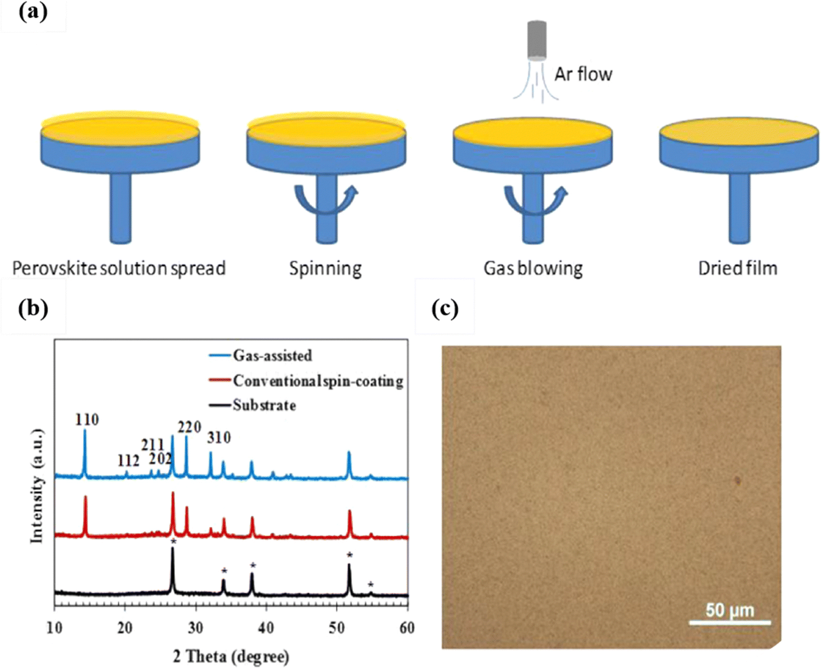 | ||
| Fig. 1 (a) Schematic procedure for the gas-assisted spin-coating method progressing from left to right; (b) XRD patterns of the FTO/glass substrate (diffraction peaks for the FTO crystal are marked), and perovskite films made by the conventional spin-coating method and the gas-assisted method; (c) an optical microscope image of the perovskite film prepared using the gas-assisted method. The films were annealed at 100 °C for 10 min. Reproduced with permission.54 Copyright 2014, Elsevier B.V. | ||
3. The development process of green antisolvent treatment
After more than ten years of development, perovskite solar cells have received widespread attention for low cost and simple operation. The two-step deposition operation is complicated and requires long-term oxidation. Although inkjet printing, printing, and spraying are conducive to large-scale production, they also have shortcomings: the need for the strictest operating environment, expensive equipment, low film coverage, and film deposition discontinuity. In comparison, the advantages of the one-step route are obvious. These include low preparation costs, simple operation, and optimized energy level matching at the interface. Additionally, the prepared perovskite film exhibits high coverage, large crystal size, and excellent performance. Green antisolvent solubility is relatively better, allowing for the formation of high-quality films. Most green antisolvents have a low boiling point and are easy to volatilize, eliminating the need for additional annealing treatments, which can significantly reduce experimental costs. Moreover, green antisolvent is environmentally friendly and human-friendly, which can simplify the treatment process. Finally, the development progress of green antisolvents is proposed, which is the basis for the development of new green antisolvents and the optimization and improvement of some green antisolvents.3.1. Single-component green antisolvents
In the early years of PSC development, toluene, chlorobenzene, and benzo trifluoride were firstly proposed as antisolvents to prepare perovskite films. With the treatment of those antisolvents, nucleation and crystal growth in the perovskite films can be optimized, with the rapid crystal growth inhibited and rapid nucleation promoted. Thus, the coverage of the film turned more even and the performance of the device was improved. However, toluene, chlorobenzene, and benzo trifluoride are toxic with pungent odors. Consequently, they are harmful to the environment and human health, making them unsuitable for large-scale production. Therefore, environmentally friendly, pollution-free, low-cost green antisolvent has become a new research direction for scientists.Most antisolvents have low polarity. When these antisolvents are introduced into the DMF solutions, the poor miscibility with DMF will lead to a small amount DMF residue after annealing, resulting in poor perovskite film morphologies. As a resolution to this problem, Li et al. used the high-polarity antisolvent isopropanol (IPA) to ensure good miscibility with DMF, and a perovskite layer with a smooth surface was obtained in this way.60
Very limited research on how surface morphologies affect the efficiency of perovskite devices has been reported. One of these works carried out by Kim et al. was published in a Nature communication. In this article, the authors found that the performance of the PSCs could be influenced by the wrinkles in perovskite thin films, while the wrinkles could be adjusted by the antisolvents. In detail, it has been found that the wrinkles in perovskite thin films occur during the stress relaxation process. The wrinkles can facilitate carrier transport in the perovskite film, by reducing defects, and improving Voc and fill factor. Furthermore, the morphology of the wrinkles could be controlled by the antisolvent diethyl ether, based on the temperature-dependent miscibility of dimethyl sulfoxide (DMSO) with diethyl ether.16
Byranvand et al. utilized diethyl ether as an antisolvent for the crystallization of perovskite thin films. It was able to generate uniformly dense films with smooth surfaces without the need for annealing treatment. The most significant advantage was the generation of large-sized crystals, coupled with a shorter crystallization time, which greatly reduced production costs.61,62
Due to the low boiling point of diethyl ether (34.6 °C), in situations where the preparation environment temperature is elevated, diethyl ether tends to evaporate, thus failing to effectively serve as a counter solvent. Wang et al. published that diisopropyl ether can also serve as an antisolvent for removing DMF. It has a higher boiling point, allowing film formation at 40 °C (suitable for high-temperature and large-scale production). This antisolvent demonstrates good crystallinity and reproducibility.63
However, it is difficult to determine the optimal treatment time for antisolvent spin-coating, and the treatment window period is short. To solve this problem, Zhao et al. found that the use of anisole as an antisolvent can extend the processing window (5–20 seconds). It is also found that there are intermolecular hydrogen-bonding forces between anisole and DMF/DMSO that play critical roles in the wide process window. Therefore, extending the processing window can protect the perovskite precursor from volatile degradation, and the final device can reach 22.7%.64
Because the commonly used antisolvents such as toluene, chlorobenzene, and ethyl ether are not at all soluble in water, they cannot protect the perovskite layer from being decomposed by water. So, when using these antisolvents, the fabrication had to be carried out in a glovebox filled with inert gas. Ethyl acetate, an organic solvent with low water solubility has been used by Troughton as an antisolvent to solve this problem. This antisolvent could absorb the tiny amount of moisture in the environment during spin-coating, to keep the perovskite dry and stable. With ethyl acetate, the films even prepared under 75% humidity all exhibited highly uniform thickness and smooth surfaces.65
However, due to its low boiling point and high volatility, ethyl acetate can lead to defective film morphologies. Yun et al. reported the use of a new green bifunctional antisolvent, methyl benzoate (MB), with a boiling point of 198 °C much higher than most of the other antisolvents. At low temperature, it worked as an antisolvent to promote rapid crystallization. During high-temperature annealing it could act as a solvent to dissolve perovskite precursor, preventing the loss of organic components during the thermal-annealing stage and effectively suppressing the formation of miscellaneous lead halide phases.66 Unfortunately, the use of the two mentioned antisolvents (EA and MB) resulted in relatively low energy conversion efficiency after film processing, indicating the need for further efficiency improvement.
In a recent paper Zhang et al. came up with a new green antisolvent, methoxybenzene, which is widely used in fragrances and cosmetics. Compared to CB, the films produced after methoxybenzene treatment showed minimal carrier recombination, lower defect density, and smoother surfaces. All these lead to a significant improvement in conversion efficiency which reached as high as 19.42%.67
In traditional lead halide perovskite batteries, as a heavy metal, lead leakage during the manufacturing process or in the long-term use will affect human health. With lower toxicity, tin-based perovskite is considered a suitable green alternative.68,69 The nucleation rate of tin-based perovskite crystals is slow, but the crystal growth rate is ultra-fast, which leads to poor film coverage and low-quality. For this reason, Su et al. used acetic acid as an antisolvent to fabricate the PSCs, because it can accelerate the nucleation rate. Besides it can form hydrogen bonds with the precursor solution, which increased the stability of the device. Furthermore, the non-volatilized residual HAc reduces the loss of organic amine salts and passivates defect states in the perovskites.70
Besides the chemicals mentioned above, some other excellent green antisolvents have also been developed, including diethyl carbonate (DEC),71,72 tetraethyl orthocarbonate (TEOC),73 ethyl lactate,74 and dimethyl carbonate.75 Here they are all termed single-component antisolvents.
The above solvents are applied in the antisolvent treatment as shown in Table 2. While these single-component antisolvents exhibit advantages such as low cost and simple operation in application, they also present drawbacks, like limited solubility with DMF/DMSO and constrained structural control to the crystallization of perovskites. Due to the varying polarities and boiling points of different anti-solvents, it is challenging to precisely control the crystal structure and morphology.
| Perovskite material | Precursor solvent | PCE [%] | Antisolvent | Antisolvent volume [μL] | PCE [%] | Ref. |
|---|---|---|---|---|---|---|
| MAPbBr3 | DMF | — | IPA | 950 | — | 59 |
| (FA0.85MA0.15)0.95Pb(I0.85Br0.15)3 | DMF/DMSO | — | n-BA | Antisolvent bath | 17.65 | 61 |
| (FAPbI3)0.875(CsPbBr3)0.125 | DMF/DMSO | 21.04 | Diethyl ether | 350 | 23.02 | 16 |
| MAPbI3 | DMF/DMSO | 17.67 | Di-isopropyl ether | 1000 | 19.07 | 62 |
| [CsPbI3]0.05[(FAPbI3)0.85(MAPbBr3)0.15]0.95 | DMF/DMSO | 19.76 | Anisole | 100–900 | 22.7 | 63 |
| CH3NH3PbI3 | DMF/DMOS | 14.5 | EA | 200 | >15 | 64 |
| (FA0.85MA0.15) Pb(I0.85Br0.15)3 | DMF/DMSO | 19.89 | MB | 350 | 22.37 | 65 |
| MAPbBr3 | DMF/DMSO | 17.79 | PhOMe | 19.42 | 66 | |
| FASnI3 | DMF/DMSO | 10.7 | HAc | 150 | 12.78 | 69 |
| FASnI3 | DMF/DMSO | 12.1 | DEC | 300–600 | 14.2 | 70 |
| MAPbI3 | DMF/DMSO | 15.38 | TEOC | 350 | 18.15 | 72 |
| Cs0.05(FA0.83MA0.17)0.95Pb(I0.83Br0.17)3 | DMF/DMSO | 17.09 | Ethyl lactate | 400 | 21.78 | 73 |
| MAPbI3 | DMF/DMSO | 15.73 | Ether/n-ethane | 1![[thin space (1/6-em)]](https://www.rsc.org/images/entities/char_2009.gif) :1 :1 |
17.08 | 75 |
| MAPbI3 | DMF | 15.18 | EA/PE | 1:0.6 |
17.19 | 76 |
| (FAPbI3)0.85(MAPbBr3)0.15 | DMF/DMSO | — | EA/Hex | 130 | 20.06 | 77 |
3.2. Mixing treatment of two antisolvents
Based on the concept of traditional hybrid-antisolvent using chlorobenzene and toluene together, researchers have developed a treatment method by taking advantage of the mixture of two antisolvents. While most single-component antisolvents can lead to an obvious enhancement in crystallization, they often fail to significantly promote nucleation, resulting in poor film coverage. When it comes to mixing anti-solvents, four aspects need to be considered: (1) complementarity: after mixing two anti-solvents, their properties and effects should enhance each other rather than canceling out or weakening each other. (2) Solubility: the two mixed anti-solvents should have good solubility to ensure even dispersion and thorough mixing of their components. (3) Stability: the mixed anti-solvents should exhibit good stability to avoid precipitation or adverse reactions during use or long-term storage. (4) Safety: the selected mixed anti-solvents should be safe for both operators and the environment, avoiding any hazardous outcomes post-mixing.Films prepared using ethyl acetate as antisolvent alone always suffer from problems such as high surface roughness, crystal orientation disorder, and pinhole gaps, partially because the residual MDF cannot be removed thoroughly from the precursor solution. To address this issue, Yi et al. reported using a mixture of ethyl acetate and petroleum ether as the antisolvent (in a ratio of 1:0.6) to fabricate the PSCs. Petroleum ether possesses unique features such as low boiling point and low polarity, allowing it to remove residual DMF effectively. As a result, the number of grain boundaries in the thin film was reduced, and carrier recombination decreased. It is beneficial to obtain a smooth film morphology with large crystals.76
To further enhance the conversion efficiency and stability of PSCs, Lee et al. utilized a mixture of ethyl acetate and ethane as the antisolvent to control the crystallization and passivate defects. As shown in Fig. 2, the resulting film exhibited a smooth and crack-free appearance, effectively reducing carrier recombination. As a result, the PCE reached an impressive 20.06%. Moreover, an astounding PCE retention of >98% is recorded after >3000 hours storage in air.77 Recently, perovskite/silicon light-emitting LEDs have received widespread attention. Xu et al. used a polymethyl methacrylate (PMMA) and tetrabutylammonium hexafluorophosphate (TBAPF6) mixture as an antisolvent to manufacture high-efficiency perovskite light-emitting devices (PeLEDs). In such devices, with phosphate ions and butylammonium ions TBAPF6 effectively passivated the defect density of perovskite. In the PL spectrum, it was found that the mixed antisolvent treatment resulted in a 7-fold enhancement compared to the control samples (without antisolvent treatment). The authors attributed this PL enhancement primarily to the suppression of carrier non-radiative recombination by the mixed antisolvent. The addition of PMMA provided protection to perovskite, preventing it from being affected by oxygen and moisture, thus enabling the fabrication of PeLEDs under air conditions. The resulting devices achieved an EQE of 10.4%, and all of this provides strong evidence that PMMA-assisted antisolvent can effectively passivate the defects of perovskite films, and this kind of antisolvent not only induces perovskite crystal growth but also passivates defects in perovskite films.78
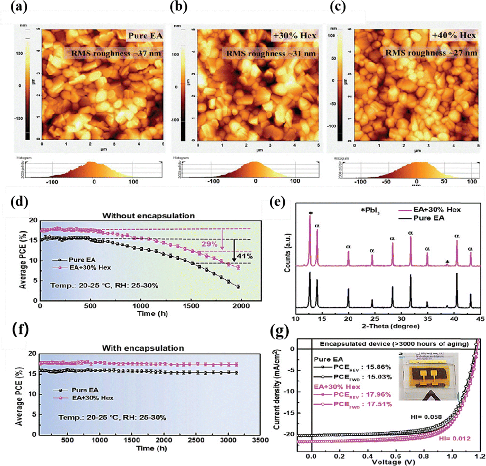 | ||
| Fig. 2 AFM topography images and RMS surface roughness of perovskite films treated with (a) pure EA, (b) EA + 30% Hex and (c) EA + 40% Hex antisolvent. Average PCE of (d) unencapsulated and (e) encapsulated PSCs as a function of storage duration under an ambient environment (temp.: 20–24 °C; RH: 25–30%). (f) Corresponding XRD spectra of the unencapsulated perovskite films after >1500 hours of storage in air. (g) J–V characteristics of representative EA and EA + 30% Hex devices after >3000 hours of aging in air; the inset shows a photograph of an encapsulated PSC device. Reproduced with permission.73 Copyright 2019, Wiley-VCH. | ||
The above introduction of the two green antisolvent mix treatment films exhibit obvious enhancement to the performance of PSCs. These good results inspired the researchers to further explore the new green hybrid antisolvent. But the key point is to accurately control the optimal ratio of the two components to help generate excellent film products.
4. High-performance green additives
When the concept of using antisolvents to reduce defects in the perovskite layer and improve film coverage was first introduced, various antisolvent methods gained significant attention, ranging from common single-component antisolvents like PhOMe,79 EA,65,80–82 and IPA,83–85 to mixed antisolvents. These approaches greatly improved the film morphologies, but they lacked precise control over the crystallization process. As such they resulted in a larger roughness of the resulting surface and the formation of excessive grain boundary defects. To address these challenges, researchers have proposed additives into the antisolvent to enhance the film morphologies and achieve a high-quality, uniform, and dense perovskite layer. These additives can be classified into categories such as fullerene derivatives, polumers, radical derivatives, and other additives.86–88 Next, we will analyze and discuss the impact of various additives on the morphologies of perovskite layers.4.1. Green polymers
Despite the encapsulation of PSCs to prevent moisture and oxygen reactions, their stability still requires further improvement under continuous light irradiation and thermal treatment. During the growth of thin film crystals, grain boundaries (GBs) are present, and the downward growth of GBs can easily result in pinholes and defects on the film surface. To solve the crystal grain problem, Wang et al. introduced an insulating moisture-proof polymer (polymethyl methacrylate PMMA) in EA, which can effectively eliminate the voids, pinholes, and GBs generated by DMSO volatilization after annealing. The carbon group (C![[double bond, length as m-dash]](https://www.rsc.org/images/entities/char_e001.gif) O) contained in PMMA can form coordination bonds with under-coordinated Pb, thereby reducing the perovskite degradation and improving the stability.89
O) contained in PMMA can form coordination bonds with under-coordinated Pb, thereby reducing the perovskite degradation and improving the stability.89
To delay rapid crystallization and to prepare devices in an air environment, Zhong et al. introduced ammonium acetate (NH4Ac) as an additive into ethyl acetate, the antisolvent. Ammonium acetate's NH4+ can form hydrogen bonds with formamidinium iodide (FAI), as shown in Fig. 3, which makes the intermediate phase more stable and enabling device fabrication in air. The optimal crystallinity was observed at an ammonium acetate concentration of 0.01 mg mL−1. Additionally, the crystal size increased to 470 nm, effectively reducing carrier recombination. The highest efficiency reached 20.41%, and the PSCs without encapsulation could maintain 82% of their initial PCE when stored under full ambient air conditions (30–40% RH) for 30 days.90
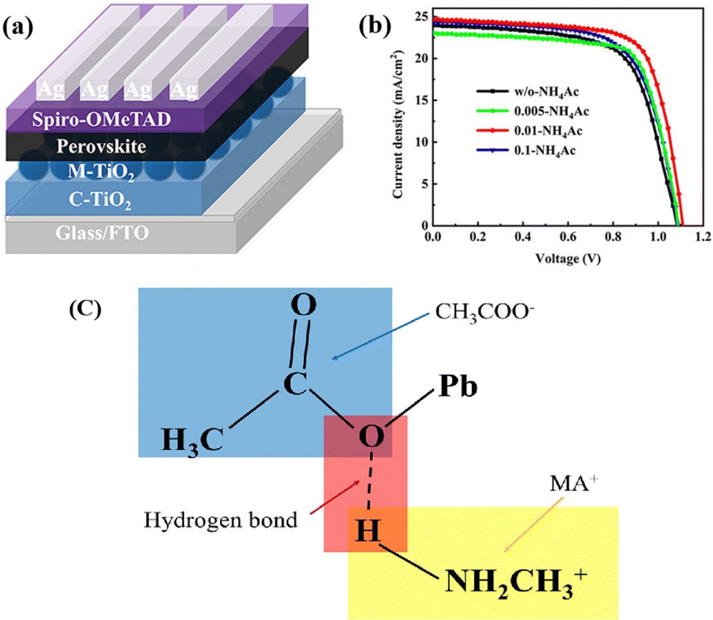 | ||
| Fig. 3 (a) Architecture of device. (b) J–V curves of champion devices under different additive concentrations. (c) Schematic diagram of the hydrogen bonding formed between CH3COO− and MA+. Reproduced with permission.86 Copyright 2021 American Chemical Society. | ||
In summary, the introduction of polymers offers several advantages in the fabrication process, including simplifying the process, increasing the efficiency, enhancing the light absorption, and improving the stability. However, polymers can undergo degradation after prolonged exposure to light, which not only affects the stability of PSCs but also forms blocking layers that restrict carrier transport. Therefore, it is crucial to select polymers that can coexist with perovskite materials for an extended period, ensuring their long-term stability.
4.2. Green radical derivatives
Currently, the presence of excessive under-coordinated Pb can lead to the formation of GBs and non-radiative recombination.91–94 Some researchers have proposed the use of additives to passivate defects, achieving the suppression of non-radiative recombination and efficiency improvement.95,96 By introducing Lewis bases with lone electron pairs to coordinate with lead ions, a new approach has been provided for defect passivation. Therefore, Xie et al. developed a radical derivative (OTTM) as a green additive to fabricate stable and efficient PSCs in air, as shown in Fig. 4, OTTM contains a methoxy group and multiple chlorine groups, which can obviously enhance the electron density of Lewis bases to reduce defects in perovskite films. The authors synthesized OHTTM as a control. In experiments, perovskite films were treated with EA and 0.5 mg mL−1 additives, either OTTM or OHTTM, in an environment with 25% air humidity. Comparing them to the OHTTM- PVK sample, the larger crystal size (0.37 μm) of the OTTM-PVK sample indicates better coordination of OTTM with the thin film, reducing the defect in the thin film and optimizing the energy level arrangement.97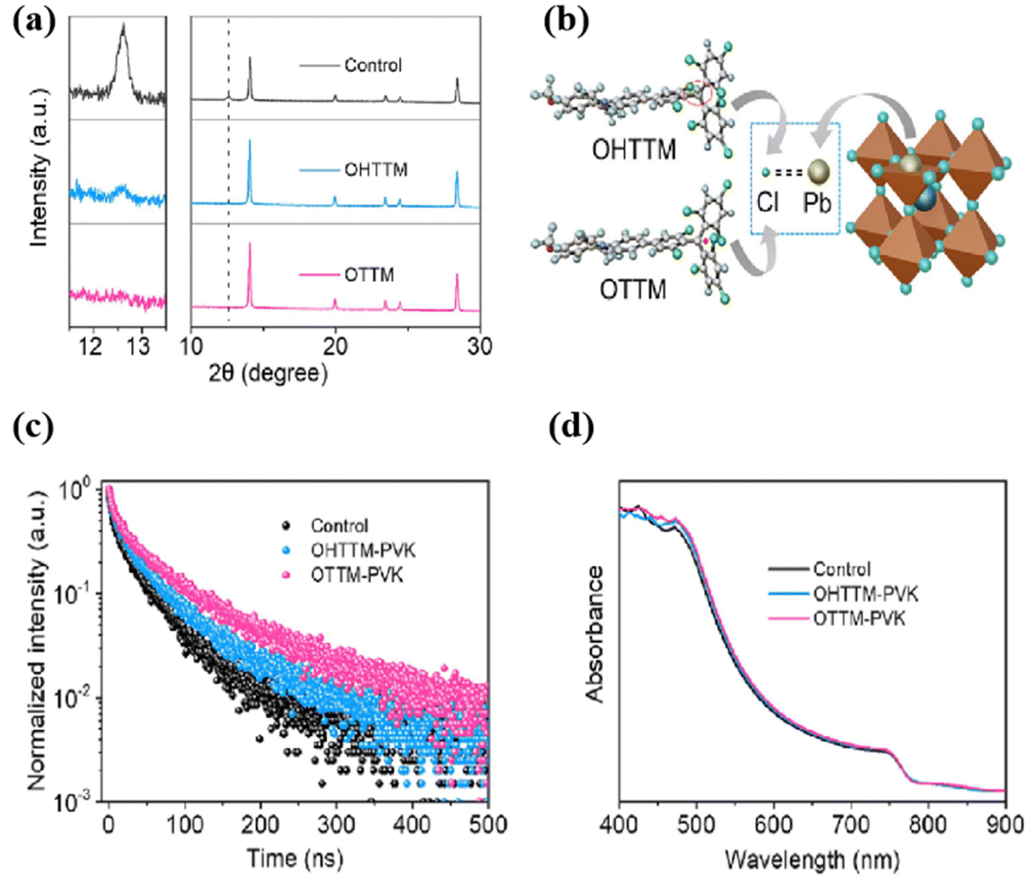 | ||
| Fig. 4 (a) XRD patterns of pristine, OHTTM-treated, and OTTM-treated perovskite films (left side, enlarged XRD patterns in the PbI2 region); (b) schematic diagram of the interaction between uncoordinated Pb2+ and Cl groups in OHTTM and OTTM; (c) time-resolved PL spectra and (d) UV-vis spectra of pristine, OHTTM-treated, and OTTM-treated perovskite films deposited on quartz. Reproduced with permission.87 Copyright 2023, Elsevier. | ||
The introduction of radical derivatives can effectively improve the crystallization, promote the carrier transport, and reduce the charge recombination. But it should be noted that the long-term work of free radical additives will lead to their decomposition and degradation, thereby affecting the morphologies of the films and reducing the stability.
4.3. Other green additives
Due to the presence of crystal boundaries, which provide shortcut pathways for charge recombination, the introduction of quantum dots (containing carboxyl and hydroxyl groups) can passivate the under-coordinated Pb at the crystal boundaries, thereby reducing non-radiative recombination and improving the efficiency and stability of PSCs.98–102Surprisingly, Xiu et al. recently reported that low-polarity green alkanes can be used as antisolvents. But when using alkanes as a single antisolvent, the inability to effectively remove excess DMSO resulted in poor film morphologies and lower PCE.103 However, after the treatment with alkanes/nanocrystals, FTIR observations revealed a shift in the SO peak of DMSO at 1020 cm−1, indicating that nanocrystals can effectively remove residual DMSO. Moreover, the phase segregation that easily occurs in the CB processed perovskite film is successfully suppressed by the alkane/nanocrystals method. Perovskite films processed with alkane/nanocrystals exhibit ultra-high stability, after continuous 500-hour MMP testing, and the efficiency only decreased by 6%.104
The introduction of quantum dots in the antisolvent can effectively improve film morphologies, but further exploration is needed to understand the underlying mechanisms of how quantum dots in antisolvents affect the film, to pave the way for the exploration of additives that can simultaneously enhance efficiency and stability. The above addition applied to antisolvent treatment is as shown in Table 3.
5. Effect of green antisolvent treatment on stability
At present, the efficiency of perovskite solar cells is comparable to silicon cells. But for commercialization, the stability of PSCs must be considered. The current working life of perovskite solar cells is about 12 months, which is much lower than that of silicon solar cells. This is mainly because PSCs can easily decompose in an environment of strong light, enriched oxygen, and high humidity. Therefore, long-term storage in air will lead to a decrease in stability. Although inorganic perovskites are relatively stable, their efficiency is too low. Therefore, improving stability is of great significance for PSC commercialization. Some works published recently have shown that treatment with antisolvents can efficiently enhance the stability of PSCs, which paves the way for accelerating commercialization. Among them, the studies using green antisolvents are listed and discussed below. The high stability of PSCs mainly depends on whether they can effectively inhibit the decomposition reaction of the film. To address this, the researchers introduced the insulating polymers PMMA into EA, the antisolvent, for treatment, as shown in Fig. 5. PMMA helped reduce gaps and pinholes at the interface. Its CO bonds can form hydrogen bonds with the NH3+ ions, enhancing the hydrophobicity of the perovskite. As a result, the prepared PSCs, treated with EA containing PMMA, exhibited a loss of only 5% in efficiency after 200 days storage in a nitrogen environment.105 Besides polymers, the addition of small organic molecules into antisolvent also led to satisfying stability. Frank et al. demonstrated that the treatment of adding acetylacetone (AA) in green solvent ethyl acetate (EA) can promote the binding of under-coordinated Pb, leading to improved film quality and increased crystal size, with a maximum PCE of 21.1%. It also exhibits better hydrophobicity, which ensured it can retain 87% of its initial efficiency after storage for 1224 hours in an 70% humidity environment without encapsulation.106
 | ||
| Fig. 5 Comparison of long-term stability (a) and (b) J–V curves, (c) the value of PCEs, and (d) normalized PCE for pristine and PMMA-passivated perovskite solar cells for storage under N2 conditions (25–30% temperature). Top-view SEM images of (e) pristine and (f) passivated perovskite films. Reproduced with permission.108 Copyright 2022, Elsevier B.V. | ||
Although significant breakthroughs have been achieved in the efficiency of most PSCs at present, stability remains the primary obstacle hindering the commercialization of PSCs. Therefore, it is crucial to explore ways to enhance the stability of PSCs. The device prepared by Wang et al. using iodine as an additive introduced into antisolvent can show high stability, and the efficiency remains at 91% after 30 days of storage at room temperature with a relative humidity of 45%, because the additive can control the crystallization process and thus effectively reduce defects, showing high hydrophobicity and benefits in terms of performance improvement.107 Subsequently, Yang et al. published the application of a new antisolvent, 2-ethyl hexanoate lead (LDE), which changed the crystallization kinetics. With delayed crystallization, a film was generated to protect the perovskite layer yielding an improved hydrophobic surface. After storage at 85 °C for 300 h, the efficiency was maintained at 85%, and the efficiency loss was only 9% after 3000 h in air with 25% humidity.108
Surprisingly, Lee et al. prepared ternary PSCs (ITO/SnO2/PVK/spiro-OMeTAD/Ag) by mixing ethyl acetate and ethane as antisolvents, and the efficiency lost was only 2% after storage in air for more than 3000 h after encapsulation. And even after storing for more than 1500 h without encapsulation, it could maintain 71% of the original efficiency.77 Recently, Sun et al. fabricated a high-quality perovskite film with (111) preferred orientation ((111)-α-FAPbI3) using a short-chain isomeric alcohol as an antisolvent. Even without annealing, the use of isopropyl alcohol (IPA) treatment resulted in the formation of α-FAPbI3 with the (111) crystal plane. The shift in the peak observed in the FTIR spectrum after IPA treatment confirmed the reaction between IPA and PbI2, which suppressed the formation of δ-FAPbI3. PSCs based on the (111)-perovskite films show 22% power conversion efficiency and excellent stability, which remains unchanged after 600 h continuous working at maximum power point, and 95% after 2000 h of storage in an atmosphere environment.109 Recently, a group of researchers introduced a low-toxicity chemical solvent called bis-diazirine (BD) molecules as an antisolvent. BD can form covalent bonds with perovskite materials, thereby reducing excessive lead and increasing stability. With this treatment, the efficiency reached 24%. After being stored at high temperatures for 1000 hours, the efficiency only experienced a minimal loss of 2.4%.110
In summary, green antisolvents took generally a lot of advantages for the stability of perovskite layers. They can reduce corrosion, degradation or oxidation, and lower the occurrence of side reactions, thus extending the life of the devices.
6. Popular green antisolvents
So far, a wide variety of solvents have been widely used as antisolvents for PSC processing. Interestingly, these various antisolvents with different properties have all been found to effectively promote crystallization and improve device performance. To explore the underlying principles, researchers have utilized multiple common antisolvents to treat the thin perovskite films and objectively evaluate the advantages and disadvantages of different antisolvents with the help of various characterization techniques. Ultimately, the most suitable antisolvent has been identified. These studies allowed us to enhance our understanding of the crystallization mechanisms with different antisolvent treatments and enable more precise control over thin film crystallization. They contributed to the search for better antisolvent, to explain the aforementioned points, six antisolvents with different properties, including toluene, chlorobenzene, p-xylene, trifluoromethyl benzene, diethyl ether, and dichloromethane, were employed. Due to variations in their dielectric constants and polarities, these solvents exhibited completely distinct kinetic behaviors. The mutual solubility between p-xylene and diethyl ether with DMF and DMSO is relatively poor, thereby inhibiting the rapid formation of perovskite. After spin-coating and annealing, non-uniform regions were observed in the central area when using the low-boiling solvents diethyl ether and dichloromethane. SEM observations showed a uniform distribution of needle-shaped crystals with a higher density in toluene, chlorobenzene, and trifluoromethyl benzene. Considering factors such as film coverage, smoothness, and stability, trifluoromethyl benzene exhibited the best.42Wang et al. researched the effects of a toxic antisolvent CB and a series of green, low-toxicity antisolvents such as anisole, di-n-butyl ether, diisopropyl ether, and diethyl ether on the crystalline morphologies of thin perovskite films. They found that the polarity of the antisolvent can precisely control the formation of intermediate phases during crystallization. Among them, devices prepared using diisopropyl ether showed the best efficiency reaching 21.26%.111 In order to further study how antisolvent polarity affects the chemical surface and the structures of the perovskite crystals, Ye et al. studied the effects of antisolvent polarity such as methyl acetate, acetone, and butanol on all-inorganic perovskite (CsPbBr3), and found that the greater the antisolvent polarity, the lower the PL quantum yield. This is mainly because the more polar the antisolvent is, the more abnormally the iodine ion loss band gap changes, thereby increasing the trap defect density. Among them, methyl acetate with low polarity, can remove unreacted residual from precursor solutions, and produce significantly fewer surface defects than acetone and butanol, exhibiting the best effect in antisolvent treatment.112
Due to the suitability for large-scale commercial production and high stability, inorganic perovskites are increasingly studied due to their exceptional chemical stability and photophysical properties. Among all-inorganic perovskites, CsPbI3 showed the highest resistance against water and oxygen. As shown in Fig. 6, Jeong et al. tried six different antisolvents (chlorobenzene, toluene, diethyl ether, anisole, ethyl acetate, and methyl acetate) in an antisolvent bath process to fabricate CsPbI3. After spin-coating the precursor solution onto the substrate, it was immersed in the bath for 30 seconds, followed by annealing at 200 °C to form the perovskite phase. SEM images revealed that the films prepared using anisole as the antisolvent exhibited the best morphologies with the fewest pinholes and defects.113
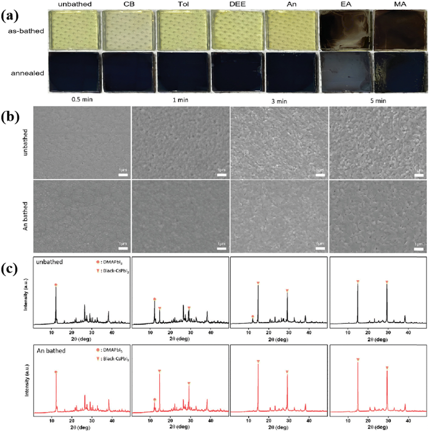 | ||
| Fig. 6 (a) Photographs of unbathed and antisolvent-bathed (CB, Tol, DEE, An, EA, and MA) films fabricated under RH 30–40%. (b) SEM images and (c) XRD patterns of the unbathed and An-bathed CsPbI3 films as a function of annealing times. Reproduced with permission.117 Copyright 2022, Wiley-VCH. | ||
Through their research of six antisolvents, namely toluene, chlorobenzene, diethyl ether, isopropyl alcohol (IPA), ethanol, and acetone, Li et al. found that their differences in boiling points, functional groups, and polarity cast a different influence on the product perovskite film. They observed that acetone, with its strong polarity, easily dissolved the perovskite, resulting in poor film quality. On the other hand, the high boiling point of chlorobenzene led to a significant residue in the film, causing unfavorable film morphologies. SEM images indicated that the film morphologies of IPA and ethanol were inferior to that of diethyl ether, chlorobenzene, and toluene, primarily due to the higher polarity of IPA and ethanol. An XRD study showed that diethyl ether exhibited the highest peaks at (110) and (220), indicating its best ability to improve film crystallization. PL measurements also revealed that diethyl ether exhibited the highest intensity, suggesting a lower non-radiative recombination rate.114,115
Although it was detected that diethyl ether left behind excessive amounts of PbI2, it still exhibited the best performance compared to the other five antisolvents. Comparisons led to the conclusion that solvents with polarity ranging within 2.0 to 4.5 were optimal for use as antisolvents.116 The above-mentioned research indicates that the influence of antisolvents on crystal growth kinetics and film morphologies primarily depends on factors such as boiling point, dielectric constant, polarity, and miscibility. When the antisolvent has poor solubility with the precursor and a low boiling point, the resulting efficiency is unsatisfactory. However, when the antisolvent exhibits good miscibility with DMF/DMSO, along with a high boiling point and low polarity, the resulting film shows high coverage, smoothness, and compactness. Through the above, it is concluded that treatment with several green solvents such as diisopropyl ether, methyl acetate, and acetone have shown a significant improvement in the stability and efficiency of the PSCs. Therefore, they have become popular green antisolvents.
7. Green antisolvent for large-area device fabrication
A key requirement for commercialization is the ability to achieve large-area production, but most laboratory perovskite films have an area of around 0.1 cm2, far from meeting commercial standards. Many researchers are also aiming to overcome this difficulty, and the preparation of large-area devices using green and pollution-free, and environmentally friendly antisolvent has also attracted widespread attention. It should also be noted that the processing window for antisolvent treatment is too short and is not conducive to uniform film formation of large-area devices. Huang et al. found that the introduction of tetrahydrothiophene 1,1-dioxide in the precursor can extend the processing window period to 90 s, as shown in Fig. 7a and b, and the OSO bond in cyclobutyl sulfone can form hydrogen bonds with methylamine ions to increase stability. The efficiency of the 49 cm2 device fabricated using this method reaches 16.06%, and the efficiency of the packaged battery only decreases by 10% after continuous testing for 250 hours in MMP.117 The main reason for limiting the large-area device production is the uneven coverage of the antisolvent on the substrate. Even with an increased amount of antisolvent up to 500 μL, the effect remains unsatisfactory. To address this issue, Bu et al. proposed the dynamic antisolvent quenching (DAS) technique, which allows for sufficient interaction between the antisolvent and the thin film, as shown in Fig. 7c and f. Moreover, the DAS technique only requires 300 μL of antisolvent to effectively form the film, significantly reducing the amount of antisolvent used. By utilizing the DAS technique, the optimal PCE of a 10 cm × 10 cm device reached 17.82%.118 Compared to spin-coating with antisolvents, the antisolvent bath method offers the advantage of simpler operation without the need to consider a short processing window. Tian et al. used n-butanol (n-BA) as the antisolvent in an antisolvent bath to fabricate large-area devices. During the immersion process, some FAI or MABr may be removed by n-BA, so a small amount of FAI or MABr needs to be added to the antisolvent to maintain the original ratio. Using this method, devices with dimensions of 10 × 10 cm2 were fabricated, achieving an efficiency of 13.85%.119
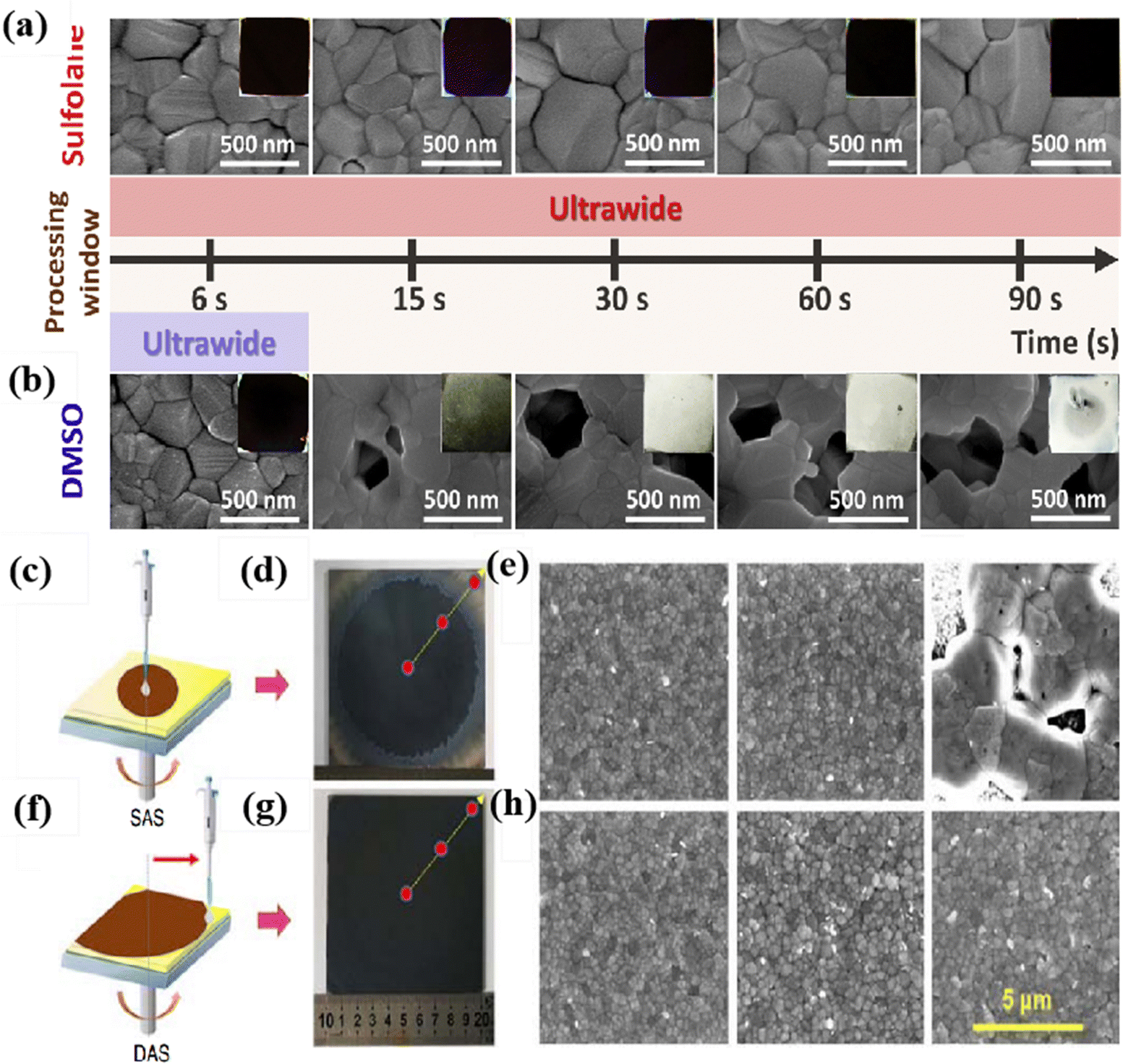 | ||
| Fig. 7 (A) and (B) Top-view SEM images of the perovskite thin film (scale bar: 500 nm) prepared by different antisolvent dripping times using (a) sulfolane precursor or (b) DMSO precursor. Reproduced with permission.121 Copyright 2021, Elsevier. (c) A schematic diagram of the SAS process and (d) a photograph of the SAS-processed large 10 × 10 cm2 perovskite film. (e) The left to right SEM images correspond to the center to the edge of the SAS-processed large 10 × 10 cm2 perovskite film. (f) A schematic diagram of the DAS process and (g) photograph of the DAS-processed large 10 × 10 cm2 perovskite film. (h) The left to right SEM images correspond to the center to the edge of the DAS-processed large 10 × 10 cm2 perovskite film. Reproduced with permission.122 Copyright 2019, Wiley-VCH. | ||
8. Prospective in antisolvent treatment
In summary, green antisolvent processing has significant advantages for large-scale perovskite production and commercialization. Next, we will discuss from two perspectives: technical-economic expectations and the future vision of green antisolvents.8.1. Technical-economic expectations
“Certainly, when turning the research focus on new and greener antisolvents, it is essential to carry out an economic analysis on the economic effects that might be caused by the introduction of green antisolvent to take the place of tradition toxic antisolvents. Here a currently widely used toxic antisolvent chlorobenzene is selected as an example for the comparison. In Table 4, the costs of chlorobenzene and the green antisolvents mentioned in this review (as shown in the table below) have been listed. In the table it can be seen that the prices of most of the green antisolvents are close to that of chlorobenzene, or some are even cheaper. This highlights their significant advantages: replacing the traditional toxic antisolvent chlorobenzene with green ones will not result in too much pressure to the total cost of solar cell production. Although the cost of some green solvents is slightly higher, considering the fact that using green solvents may reduce the pollution to environments, as well as decrease the potential hazard to workers during both solar cell production, and the transport and storage of these materials, such extra expense in green antisolvents should be acceptable to the solar cell producers. Furthermore, they also have to fulfill the environmental protection requirements from governments, which is another motivation for the producers to use those green antisolvents instead the toxic ones. Considering all these economic factors collectively, the promotion of those green solvents and the exploration for new and better ones through research should be in high demand in the recent future.| Antisolvent | Price kg per USD |
|---|---|
| Chlorobenzene | 1.0085 |
| EA | 0.967 |
| IPA | 0.8289 |
| Di-isopropyl ether | 3.3157 |
| Anisole | 2.4591 |
| Acetic acid | 0.4559 |
| Methyl benzoate | 607.87 |
| Diethyl carbonate | 1.3815 |
| Tetraethyl orthocarbonate | 4144.5 |
| Ethyl lactate | 69.076 |
| Dimethyl carbonate | 0.6908 |
Overall, these results demonstrate the considerable economic feasibility of green antisolvents.120–123
8.2. The future vision of green antisolvents
The future vision of green antisolvents can be outlined from the following four directions: (1) following the trend of environment policy: most of the governments in the current world are paying more and more attention to environment protection, and the policies are becoming progressively strict. According to this trend, the manufacturers are required to develop more environment-friendly fabrication processes. The replacement of traditional toxic solvents with green ones will be welcomed by the producers of next generation perovskite solar cells. (2) Efficiency and stability: By developing green antisolvents optimized for the properties of perovskite materials, efficiency and stability will not be compromised, but improved. These green antisolvents should effectively form uniform and high-quality perovskite thin films, enhancing electron and hole transport efficiency. (3) Simplified production processes, low costs, and scalability: Through the development of green antisolvent technologies pursuing simple production processes, low costs, and easiness in scaling up sustainable industrial production can be achieved. (4) Wide-ranging applications: green antisolvents for perovskite materials can also be applied in other fields such as solar cells, optoelectronic devices, and photocatalysis. This will help reduce the reliance on traditional toxic antisolvents and promote the development of green chemistry engineering. Overall, the future vision of green antisolvents for perovskite materials is to achieve environmental friendliness and high efficiency, contributing to sustainable development and the growth of a clean energy industry.64,1249. Conclusion and outlook
In the fabrication of PSCs, antisolvent treatment is conducive to crystal growth by promoting rapid nucleation while inhibiting excessive crystal growth. All these effects result in favorable film morphologies after antisolvent treatment. But many of the solvents often used in such treatment are toxic, which is not only hazardous to workers and the environment, but also affects the progress of commercialization. So green antisolvents with low toxicity are of significance to the development of PSCs in the future. In this review, by comparing the morphologies and quality of films after treatment with various antisolvents, we have listed a series of green antisolvents with high miscibility with DMSO/DMF, low polarity, and high boiling points which can generate uniform, dense perovskite films without pinholes. Due to the current challenges of low stability of PSCs and the difficulties in preparing large-area ones of them, some researchers have sought to enhance the stability by introducing certain green solvents in the post-treatment of films. Simultaneously, some green and cost-effective methods for large-scale production have been developed.Although there are some shortcomings, processing perovskite films with antisolvents, especially with green antisolvent, in the fabrication for PSCs will continue to be the primary technical approach in the future. Due to the simplicity of antisolvent operation and its low production cost, along with material improvements and process optimization, the efficiency and stability of PSCs fabricated with antisolvents can be expected for further enhancements. In short, the future of green antisolvents will increasingly prioritize sustainability. Researchers will keep searching for greener and renewable antisolvents to reduce reliance on the traditional toxic ones.
Conflicts of interest
There are no conflicts to declare.Acknowledgements
This work was financially supported by Sichuan Engineering Technology Research Center of Basalt Fiber Composites Development and Application (2022SCXWYXWFC006), the Natural Science Foundation of Sichuan Province (2022NSFSC0356), the National Natural Science Foundation of China (52376210) and the Chengdu Science and Technology Program (2021GH0200032HZ).References
- D. Bi, W. Tress, M. I. Dar, P. Gao, J. Luo, C. Renevier, K. Schenk, A. Abate, F. Giordano, J.-P. Correa Baena, J.-D. Decoppet, S. M. Zakeeruddin, M. K. Nazeeruddin, M. Grätzel and A. Hagfeldt, Sci. Adv., 2016, 2, e1501170 CrossRef PubMed.
- J. H. Heo, S. H. Im, J. H. Noh, T. N. Mandal, C.-S. Lim, J. A. Chang, Y. H. Lee, H.-J. Kim, A. Sarkar, M. K. Nazeeruddin, M. Grätzel and S. I. Seok, Nat. Photonics, 2013, 7, 486–491 CrossRef CAS.
- Q. Dong, Y. Fang, Y. Shao, P. Mulligan, J. Qiu, L. Cao and J. Huang, Science, 2015, 347, 967–970 CrossRef CAS PubMed.
- X. Li, D. Bi, C. Yi, J.-D. Décoppet, J. Luo, S. M. Zakeeruddin, A. Hagfeldt and M. Grätzel, Science, 2016, 353, 58–62 CrossRef CAS PubMed.
- J. Lim, M. T. Hörantner, N. Sakai, J. M. Ball, S. Mahesh, N. K. Noel, Y.-H. Lin, J. B. Patel, D. P. McMeekin, M. B. Johnston, B. Wenger and H. J. Snaith, Energy Environ. Sci., 2019, 12, 169–176 RSC.
- J. H. Noh, S. H. Im, J. H. Heo, T. N. Mandal and S. I. Seok, Nano Lett., 2013, 13, 1764–1769 CrossRef CAS PubMed.
- T. Singh and T. Miyasaka, Adv. Energy Mater., 2018, 8, 1700677 CrossRef.
- S. D. Stranks, G. E. Eperon, G. Grancini, C. Menelaou, M. J. P. Alcocer, T. Leijtens, L. M. Herz, A. Petrozza and H. J. Snaith, Science, 2013, 342, 341–344 CrossRef CAS PubMed.
- T. Wang, B. Daiber, J. M. Frost, S. A. Mann, E. C. Garnett, A. Walsh and B. Ehrler, Energy Environ. Sci., 2017, 10, 509–515 RSC.
- G. Xing, N. Mathews, S. Sun, S. S. Lim, Y. M. Lam, M. Grätzel, S. Mhaisalkar and T. C. Sum, Science, 2013, 342, 344–347 CrossRef CAS PubMed.
- Q. Xu, B. Shi, Y. Li, J. Liu, Y. Li, Z. SunLi, P. Liu, Y. Zhang, C. Sun, W. Han, Q. Huang, D. Zhang, H. Ren, X. Du, Y. Zhao and X. Zhang, Adv. Mater., 2024, 36, 2308692 CrossRef CAS PubMed.
- B. Li, C. Zhang, D. Gao, X. Sun, S. Zhang, Z. Li, J. Gong, S. Li and Z. Zhu, Adv. Mater., 2023, 2309768 Search PubMed.
- T. Ma, H. Wang, Z. Wu, Y. Zhao, C. Chen, X. Yin, L. Hu, F. Yao, Q. Lin, S. Wang, D. Zhao, X. Li and C. Wang, Adv. Mater., 2024, 36, 2308240 CrossRef CAS PubMed.
- Y. Zhu, M. Hu, M. Xu, B. Zhang, F. Huang, Y.-B. Cheng and J. Lu, Mater. Futures, 2022, 1, 042102 CrossRef CAS.
- Y. Zhao and K. Zhu, J. Phys. Chem. Lett., 2014, 5, 4175–4186 CrossRef CAS PubMed.
- S.-G. Kim, J.-H. Kim, P. Ramming, Y. Zhong, K. Schötz, S. J. Kwon, S. Huettner, F. Panzer and N.-G. Park, Nat. Commun., 2021, 12, 1554 CrossRef CAS PubMed.
- T. Zhu, Y. Yang, S. Zhou, X. Yao, L. Liu, W. Hu and X. Gong, Chin. Chem. Lett., 2020, 31, 2249–2253 CrossRef CAS.
- M. Kong, H. Hu, K. Egbo, B. Dong, L. Wan and S. Wang, Chin. Chem. Lett., 2019, 30, 1325–1328 CrossRef CAS.
- Z. Xiao, C. Bi, Y. Shao, Q. Dong, Q. Wang, Y. Yuan, C. Wang, Y. Gao and J. Huang, Energy Environ. Sci., 2014, 7, 2619–2623 RSC.
- A. M. Elseman, W. Sharmoukh, S. Sajid, P. Cui, J. Ji, S. Dou, D. Wei, H. Huang, W. Xi, L. Chu, Y. Li, B. Jiang and M. Li, Adv. Sci., 2018, 5, 1800568 CrossRef PubMed.
- A. E. Shalan, W. Sharmoukh, A. N. Elshazly, M. M. Elnagar, S. A. Al Kiey, M. M. Rashad and N. K. Allam, Sustainable Mater. Technol., 2020, 26, e00226 CrossRef CAS.
- T. Liu, Y. Liu, X. Gao and J. Cao, Chin. Chem. Lett., 2023, 34, 107883 CrossRef CAS.
- M. Liu, M. B. Johnston and H. J. Snaith, Nature, 2013, 501, 395–398 CrossRef CAS PubMed.
- R. Sedighi, F. Tajabadi, S. Shahbazi, S. Gholipour and N. Taghavinia, ChemPhysChem, 2016, 17, 2382–2388 CrossRef CAS PubMed.
- Y. Zhao and K. Zhu, J. Mater. Chem. A, 2015, 3, 9086–9091 RSC.
- Z. Yi, W. Wang, R. He, J. Zhu, W. Jiao, Y. Luo, Y. Xu, Y. Wang, Z. Zeng, K. Wei, J. Zhang, S.-W. Tsang, C. Chen, W. Tang and D. Zhao, Energy Environ. Sci., 2024, 17, 202–209 RSC.
- J. Zheng, Z. Ying, Z. Yang, Z. Lin, H. Wei, L. Chen, X. Yang, Y. Zeng, X. Li and J. Ye, Nat. Energy, 2023, 8, 1250–1261 CrossRef CAS.
- J. Wen, Y. Zhao, P. Wu, Y. Liu, X. Zheng, R. Lin, S. Wan, K. Li, H. Luo, Y. Tian, L. Li and H. Tan, Nat. Commun., 2023, 14, 7118 CrossRef CAS PubMed.
- J. Burschka, N. Pellet, S.-J. Moon, R. Humphry-Baker, P. Gao, M. K. Nazeeruddin and M. Grätzel, Nature, 2013, 499, 316–319 CrossRef CAS PubMed.
- N. J. Jeon, J. H. Noh, Y. C. Kim, W. S. Yang, S. Ryu and S. I. Seok, Nat. Mater., 2014, 13, 897–903 CrossRef CAS PubMed.
- J. Park, J. Kim, H.-S. Yun, M. J. Paik, E. Noh, H. J. Mun, M. G. Kim, T. J. Shin and S. I. Seok, Nature, 2023, 616, 724–730 CrossRef CAS PubMed.
- Z. Huang, Y. Bai, X. Huang, J. Li, Y. Wu, Y. Chen, K. Li, X. Niu, N. Li, G. Liu, Y. Zhang, H. Zai, Q. Chen, T. Lei, L. Wang and H. Zhou, Nature, 2023, 623, 531–537 CrossRef CAS PubMed.
- H. Chen, C. Liu, J. Xu, A. Maxwell, W. Zhou, Y. Yang, Q. Zhou, A. S. R. Bati, H. Wan, Z. Wang, L. Zeng, J. Wang, P. Serles, Y. Liu, S. Teale, Y. Liu, M. I. Saidaminov, M. Li, N. Rolston, S. Hoogland, T. Filleter, M. G. Kanatzidis, B. Chen, Z. Ning and E. H. Sargent, Science, 2024, 384, 189–193 CrossRef CAS PubMed.
- W. Ren, J. Ren, Y. Wu, S. Li, Q. Sun and Y. Hao, Adv. Funct. Mater., 2024, 34, 2311260 CrossRef CAS.
- M. Wang, S. Tan, Y. Zhao, P. Zhu, Y. Yin, Y. Feng, T. Huang, J. Xue, R. Wang, G. S. Han, H. S. Jung, J. Bian, J.-W. Lee and Y. Yang, Adv. Funct. Mater., 2021, 31, 2007520 CrossRef CAS.
- H. Shen, R. Nan, Z. Jian and X. Li, J. Mater. Sci., 2019, 54, 11596–11603 CrossRef CAS.
- D. Shi, V. Adinolfi, R. Comin, M. Yuan, E. Alarousu, A. Buin, Y. Chen, S. Hoogland, A. Rothenberger, K. Katsiev, Y. Losovyj, X. Zhang, P. A. Dowben, O. F. Mohammed, E. H. Sargent and O. M. Bakr, Science, 2015, 347, 519–522 CrossRef CAS PubMed.
- J. Sun, F. Li, J. Yuan and W. Ma, Small Methods, 2021, 5, 2100046 CrossRef CAS PubMed.
- Y.-K. Ren, X.-H. Ding, Y.-H. Wu, J. Zhu, T. Hayat, A. Alsaedi, Y.-F. Xu, Z.-Q. Li, S.-F. Yang and S.-Y. Dai, J. Mater. Chem. A, 2017, 5, 20327–20333 RSC.
- H. Taherianfard, G.-W. Kim, M. M. Byranvand, K. Choi, G. Kang, H. Choi, F. Tajabadi, N. Taghavinia and T. Park, ACS Appl. Energy Mater., 2020, 3, 1506–1514 CrossRef CAS.
- D. Xin, Z. Wang, M. Zhang, X. Zheng, Y. Qin, J. Zhu and W.-H. Zhang, ACS Sustainable Chem. Eng., 2019, 7, 4343–4350 CrossRef CAS.
- S. Paek, P. Schouwink, E. N. Athanasopoulou, K. T. Cho, G. Grancini, Y. Lee, Y. Zhang, F. Stellacci, M. K. Nazeeruddin and P. Gao, Chem. Mater., 2017, 29, 3490–3498 CrossRef CAS.
- Y. Tong, A. Najar, L. Wang, L. Liu, M. Du, J. Yang, J. Li, K. Wang and S. Liu, Adv. Sci., 2022, 9, 2105085 CrossRef CAS PubMed.
- Y. Jiang, L. Qiu, E. J. Juarez-Perez, L. K. Ono, Z. Hu, Z. Liu, Z. Wu, L. Meng, Q. Wang and Y. Qi, Nat. Energy, 2019, 4, 585–593 CrossRef CAS.
- S. Ma, Y. Bai, H. Wang, H. Zai, J. Wu, L. Li, S. Xiang, N. Liu, L. Liu, C. Zhu, G. Liu, X. Niu, H. Chen, H. Zhou, Y. Li and Q. Chen, Adv. Energy Mater., 2020, 10, 1902472 CrossRef CAS.
- H. Back, J. Kim, G. Kim, T. Kyun Kim, H. Kang, J. Kong, S. Ho Lee and K. Lee, Sol. Energy Mater. Sol. Cells, 2016, 144, 309–315 CrossRef CAS.
- Y. Deng, E. Peng, Y. Shao, Z. Xiao, Q. Dong and J. Huang, Energy Environ. Sci., 2015, 8, 1544–1550 RSC.
- D. Lee, Y.-S. Jung, Y.-J. Heo, S. Lee, K. Hwang, Y.-J. Jeon, J.-E. Kim, J. Park, G. Y. Jung and D.-Y. Kim, ACS Appl. Mater. Interfaces, 2018, 10, 16133–16139 CrossRef CAS PubMed.
- A. Raj, M. Kumar and A. Anshul, Mater. Lett., 2023, 340, 134171 CrossRef CAS.
- K. Hwang, Y.-S. Jung, Y.-J. Heo, F. H. Scholes, S. E. Watkins, J. Subbiah, D. J. Jones, D.-Y. Kim and D. Vak, Adv. Mater., 2015, 27, 1241–1247 CrossRef CAS PubMed.
- J. Liu, D. Zheng, K. Wang, Z. Li, S. Liu, L. Peng and D. Yang, Joule, 2024, 8(4), 944–969 CrossRef CAS.
- A. C. Flick, N. Rolston and R. H. Dauskardt, Adv. Energy Mater., 2024, 14, 2303175 CrossRef CAS.
- C. Liu, Y.-B. Cheng and Z. Ge, Chem. Soc. Rev., 2020, 49, 1653–1687 RSC.
- M. Kim, G.-H. Kim, K. S. Oh, Y. Jo, H. Yoon, K.-H. Kim, H. Lee, J. Y. Kim and D. S. Kim, ACS Nano, 2017, 11, 6057–6064 CrossRef CAS PubMed.
- D. Zheng, F. Raffin, P. Volovitch and T. Pauporté, Nat. Commun., 2022, 13, 6655 CrossRef CAS PubMed.
- S. Chen, X. Xiao, B. Chen, L. L. Kelly, J. Zhao, Y. Lin, M. F. Toney and J. Huang, Sci. Adv., 2021, 7, eabb2412 CrossRef CAS PubMed.
- A. A. Zhumekenov, V. M. Burlakov, M. I. Saidaminov, A. Alofi, M. A. Haque, B. Turedi, B. Davaasuren, I. Dursun, N. Cho, A. M. El-Zohry, M. De Bastiani, A. Giugni, B. Torre, E. Di Fabrizio, O. F. Mohammed, A. Rothenberger, T. Wu, A. Goriely and O. M. Bakr, ACS Energy Lett., 2017, 2, 1782–1788 CrossRef CAS.
- F. Huang, Y. Dkhissi, W. Huang, M. Xiao, I. Benesperi, S. Rubanov, Y. Zhu, X. Lin, L. Jiang, Y. Zhou, A. Gray-Weale, J. Etheridge, C. R. McNeill, R. A. Caruso, U. Bach, L. Spiccia and Y.-B. Cheng, Nano Energy, 2014, 10, 10–18 CrossRef CAS.
- D. Bi, C. Yi, J. Luo, J.-D. Décoppet, F. Zhang, S. M. Zakeeruddin, X. Li, A. Hagfeldt and M. Grätzel, Nat. Energy, 2016, 1, 16142 CrossRef CAS.
- Y. Li, J. F. Galisteo-López, M. E. Calvo and H. Míguez, ACS Appl. Mater. Interfaces, 2017, 9, 35505–35510 CrossRef CAS PubMed.
- M. M. Byranvand, S. Song, L. Pyeon, G. Kang, G.-Y. Lee and T. Park, Nano Energy, 2017, 34, 181–187 CrossRef CAS.
- H. Wang, W. Zeng and R. Xia, Thin Solid Films, 2018, 663, 9–13 CrossRef CAS.
- L.-Y. Wang, L.-L. Deng, X. Wang, T. Wang, H.-R. Liu, S.-M. Dai, Z. Xing, S.-Y. Xie, R.-B. Huang and L.-S. Zheng, Nanoscale, 2017, 9, 17893–17901 RSC.
- S. Attique, N. Ali, S. Rauf, S. Ali, A. Khesro, R. Khatoon, E. U. Khan, F. Akram, S. Yang and H. Wu, Sol. RRL, 2021, 5, 2100212 CrossRef CAS.
- J. Troughton, K. Hooper and T. M. Watson, Nano Energy, 2017, 39, 60–68 CrossRef CAS.
- Y. Yun, F. Wang, H. Huang, Y. Fang, S. Liu, W. Huang, Z. Cheng, Y. Liu, Y. Cao, M. Gao, L. Zhu, L. Wang, T. Qin and W. Huang, Adv. Mater., 2020, 32, 1907123 CrossRef CAS PubMed.
- M. Zhang, Z. Wang, B. Zhou, X. Jia, Q. Ma, N. Yuan, X. Zheng, J. Ding and W.-H. Zhang, Sol. RRL, 2018, 2, 1700213 CrossRef.
- W. Ke and M. G. Kanatzidis, Nat. Commun., 2019, 10, 965 CrossRef PubMed.
- J. Wang, Z. Gao, J. Yang, M. Lv, H. Chen, D.-J. Xue, X. Meng and S. Yang, Adv. Energy Mater., 2021, 11, 2102131 CrossRef CAS.
- Y. Su, J. Yang, H. Rao, Y. Zhong, W. Sheng, L. Tan and Y. Chen, Energy Environ. Sci., 2023, 16, 2177–2186 RSC.
- N. Zhang, Z. Zhang, T. Liu, T. He, P. Liu, J. Li, F. Yang, G. Song, Z. Liu and M. Yuan, Org. Electron., 2023, 113, 106709 CrossRef CAS.
- Z. Zhang, Y. Huang, C. Wang, Y. Jiang, J. Jin, J. Xu, Z. Li, Z. Su, Q. Zhou, J. Zhu, R. He, D. Hou, H. Lai, S. Ren, C. Chen, X. Gao, T. Shi, W. Hu, F. Fu, P. Gao and D. Zhao, Energy Environ. Sci., 2023, 16, 3430–3440 RSC.
- M. Wang, Q. Fu, L. Yan, J. Huang, Q. Ma, M. Humayun, W. Pi, X. Chen, Z. Zheng and W. Luo, Chem. Eng. J., 2020, 387, 123966 CrossRef CAS.
- S. M. Majeed, M. K. A. Mohammed and D. S. Ahmed, J. Mater. Chem. C, 2022, 10, 16480–16491 RSC.
- Y.-W. Zhang, Z.-L. Diao, J.-Y. Chen, W.-Y. Tan, Y.-N. Qian, L.-G. Xiao and Y. Min, J. Mater. Chem. C, 2021, 9, 8939–8946 RSC.
- J. Yi, J. Zhuang, Z. Ma, Z. Guo, W. Zhou, S. Zhao, H. Zhang, X. Luo and H. Li, Org. Electron., 2019, 69, 69–76 CrossRef CAS.
- H. B. Lee, M.-K. Jeon, N. Kumar, B. Tyagi and J.-W. Kang, Adv. Funct. Mater., 2019, 29, 1903213 CrossRef.
- X. Xu, T. Zhu, K. Xiao, Y. Zhu, J. Chen, D. Li, L. Xu, J. Xu and K. Chen, Adv. Opt. Mater., 2022, 10, 2102848 CrossRef CAS.
- Y. Yu, S. Yang, L. Lei, Q. Cao, J. Shao, S. Zhang and Y. Liu, ACS Appl. Mater. Interfaces, 2017, 9, 3667–3676 CrossRef CAS PubMed.
- X. Zhang, X. Li, L. Tao, Z. Zhang, H. Ling, X. Fu, S. Wang, M. J. Ko, J. Luo, J. Chen and Y. Li, Small, 2023, 19, 2208289 CrossRef CAS PubMed.
- Q. Huang, S. Jiang, Y. Wang, J. Jiang, Y. Chen, J. Xu, H. Qiu, C. Su and D. Chen, Nano Res., 2023, 16, 9280–9288 CrossRef CAS.
- Y. Y. Kim, T.-Y. Yang, R. Suhonen, A. Kemppainen, K. Hwang, N. J. Jeon and J. Seo, Nat. Commun., 2020, 11, 5146 CrossRef CAS PubMed.
- Z. Shariatinia, in Nano Tools and Devices for Enhanced Renewable Energy, ed. S. Devasahayam and C. M. Hussain, Elsevier, 2021, pp. 377–427 DOI:10.1016/B978-0-12-821709-2.00021-9.
- J. J. Yoo, S. Wieghold, M. C. Sponseller, M. R. Chua, S. N. Bertram, N. T. P. Hartono, J. S. Tresback, E. C. Hansen, J.-P. Correa-Baena, V. Bulović, T. Buonassisi, S. S. Shin and M. G. Bawendi, Energy Environ. Sci., 2019, 12, 2192–2199 RSC.
- S. Tan, T. Huang, I. Yavuz, R. Wang, M. H. Weber, Y. Zhao, M. Abdelsamie, M. E. Liao, H.-C. Wang, K. Huynh, K.-H. Wei, J. Xue, F. Babbe, M. S. Goorsky, J.-W. Lee, C. M. Sutter-Fella and Y. Yang, J. Am. Chem. Soc., 2021, 143, 6781–6786 CrossRef CAS PubMed.
- L. Zhu, H. Cao, C. Xue, H. Zhang, M. Qin, J. Wang, K. Wen, Z. Fu, T. Jiang, L. Xu, Y. Zhang, Y. Cao, C. Tu, J. Zhang, D. Liu, G. Zhang, D. Kong, N. Fan, G. Li, C. Yi, Q. Peng, J. Chang, X. Lu, N. Wang, W. Huang and J. Wang, Nat. Commun., 2021, 12, 5081 CrossRef CAS PubMed.
- D.-K. Lee and N.-G. Park, Appl. Phys. Rev., 2023, 10 Search PubMed.
- Y.-H. Lin, N. Sakai, P. Da, J. Wu, H. C. Sansom, A. J. Ramadan, S. Mahesh, J. Liu, R. D. J. Oliver, J. Lim, L. Aspitarte, K. Sharma, P. K. Madhu, A. B. Morales-Vilches, P. K. Nayak, S. Bai, F. Gao, C. R. M. Grovenor, M. B. Johnston, J. G. Labram, J. R. Durrant, J. M. Ball, B. Wenger, B. Stannowski and H. J. Snaith, Science, 2020, 369, 96–102 CrossRef CAS PubMed.
- Z. Wang, L. Liu, Y. Wang, Y. Ma, Z. Yang, M. Wan, H. Zhu, T. Mahmoudi, Y.-B. Hahn and Y. Mai, Chem. Eng. J., 2023, 457, 141204 CrossRef CAS.
- T. Zhong, L. Shi, H. Hao, J. Dong, K. Tang, X. Xu, S. L. Hamukwaya, H. Liu and J. Xing, ACS Sustainable Chem. Eng., 2021, 9, 13010–13020 CrossRef CAS.
- S. Chen, K. R. Choudhury, J. Subbiah, C. M. Amb, J. R. Reynolds and F. So, Adv. Energy Mater., 2011, 1, 963–969 CrossRef CAS.
- P.-Y. Lin, T. Wu, M. Ahmadi, L. Liu, S. Haacke, T.-F. Guo and B. Hu, Nano Energy, 2017, 36, 95–101 CrossRef CAS.
- T. S. Sherkar, C. Momblona, L. Gil-Escrig, J. Ávila, M. Sessolo, H. J. Bolink and L. J. A. Koster, ACS Energy Lett., 2017, 2, 1214–1222 CrossRef CAS PubMed.
- Y. Zhang, L. Tan, Q. Fu, L. Chen, T. Ji, X. Hu and Y. Chen, Chem. Commun., 2016, 52, 5674–5677 RSC.
- F. Zhang and K. Zhu, Adv. Energy Mater., 2020, 10, 1902579 CrossRef CAS.
- Y. Ma, H. Zhang, Y. Zhang, R. Hu, M. Jiang, R. Zhang, H. Lv, J. Tian, L. Chu, J. Zhang, Q. Xue, H.-L. Yip, R. Xia, X. A. Li and W. Huang, ACS Appl. Mater. Interfaces, 2019, 11, 3044–3052 CrossRef CAS PubMed.
- P. Xie, H. Xiao, Y. Qiao, G. Qu, J. Chen, X. Liu and Z.-X. Xu, Chem. Eng. J., 2023, 462, 142328 CrossRef CAS.
- M. Hao, Y. Bai, S. Zeiske, L. Ren, J. Liu, Y. Yuan, N. Zarrabi, N. Cheng, M. Ghasemi, P. Chen, M. Lyu, D. He, J.-H. Yun, Y. Du, Y. Wang, S. Ding, A. Armin, P. Meredith, G. Liu, H.-M. Cheng and L. Wang, Nat. Energy, 2020, 5, 79–88 CrossRef CAS.
- A. Hazarika, Q. Zhao, E. A. Gaulding, J. A. Christians, B. Dou, A. R. Marshall, T. Moot, J. J. Berry, J. C. Johnson and J. M. Luther, ACS Nano, 2018, 12, 10327–10337 CrossRef CAS PubMed.
- I. Lignos, V. Morad, Y. Shynkarenko, C. Bernasconi, R. M. Maceiczyk, L. Protesescu, F. Bertolotti, S. Kumar, S. T. Ochsenbein, N. Masciocchi, A. Guagliardi, C.-J. Shih, M. I. Bodnarchuk, A. J. deMello and M. V. Kovalenko, ACS Nano, 2018, 12, 5504–5517 CrossRef CAS PubMed.
- L. Protesescu, S. Yakunin, S. Kumar, J. Bär, F. Bertolotti, N. Masciocchi, A. Guagliardi, M. Grotevent, I. Shorubalko, M. I. Bodnarchuk, C.-J. Shih and M. V. Kovalenko, ACS Nano, 2017, 11, 3119–3134 CrossRef CAS PubMed.
- D. Jia, J. Chen, R. Zhuang, Y. Hua and X. Zhang, Adv. Mater., 2023, 35, 2212160 CrossRef CAS PubMed.
- N. Lin, J. Qiao, H. Dong, F. Ma and L. Wang, J. Mater. Chem. A, 2015, 3, 22839–22845 RSC.
- J. Xiu, B. Han, H. Gao, X. Chen, Z. Chen, S. Gong, X. Yan, W. Tian, X. Zhang, T. Chen, X. Feng, G. Chen, D. He, Y. Deng, S. Jin, P. R. Slater and Z. He, Adv. Energy Mater., 2023, 13, 2300566 CrossRef CAS.
- S. Ye, H. Rao, Z. Zhao, L. Zhang, H. Bao, W. Sun, Y. Li, F. Gu, J. Wang, Z. Liu, Z. Bian and C. Huang, J. Am. Chem. Soc., 2017, 139, 7504–7512 CrossRef CAS PubMed.
- J. Li, X. Hua, F. Gao, X. Ren, C. Zhang, Y. Han, Y. Li, B. Shi and S. Liu, J. Energy Chem., 2022, 66, 1–8 CrossRef.
- F. Wang, M. Yang, S. Yang, X. Qu, L. Yang, L. Fan, J. Yang and F. Rosei, Nano Energy, 2020, 67, 104224 CrossRef CAS.
- T. Yang, W. Zhao, Y. Yang, W. Huang, K. Zhao and S. Liu, Adv. Mater., 2023, 35, 2211006 CrossRef CAS PubMed.
- X. Sun, D. Li, L. Zhao, Y. Zhang, Q. Hu, T. P. Russell, F. Liu, J. Wei and H. Li, Adv. Mater., 2023, 35, 2301115 CrossRef CAS PubMed.
- K. Liu, S. Rafique, S. F. Musolino, Z. Cai, F. Liu, X. Li, Y. Yuan, Q. Bao, Y. Yang, J. Chu, X. Peng, C. Nie, W. Yuan, S. Zhang, J. Wang, Y. Pan, H. Zhang, X. Cai, Z. Shi, C. Li, H. Wang, L. Deng, T. Hu, Y. Wang, Y. Wang, S. Chen, L. Shi, P. Ayala, J. E. Wulff, A. Yu and Y. Zhan, Joule, 2023, 7, 1033–1050 CrossRef CAS.
- L. Wang, X. Wang, L.-L. Deng, S. Leng, X. Guo, C.-H. Tan, W. C. H. Choy and C.-C. Chen, Mater. Horiz., 2020, 7, 934–942 RSC.
- J. Ye, Z. Li, D. J. Kubicki, Y. Zhang, L. Dai, C. Otero-Martínez, M. A. Reus, R. Arul, K. R. Dudipala, Z. Andaji-Garmaroudi, Y.-T. Huang, Z. Li, Z. Chen, P. Müller-Buschbaum, H.-L. Yip, S. D. Stranks, C. P. Grey, J. J. Baumberg, N. C. Greenham, L. Polavarapu, A. Rao and R. L. Z. Hoye, J. Am. Chem. Soc., 2022, 144, 12102–12115 CrossRef CAS PubMed.
- W. Jeong, G. Jang, S. Ma, J. Son, C. U. Lee, J. Lee, H. Im and J. Moon, Adv. Funct. Mater., 2022, 32, 2207342 CrossRef CAS.
- J. Chen, Y. Xiong, Y. Rong, A. Mei, Y. Sheng, P. Jiang, Y. Hu, X. Li and H. Han, Nano Energy, 2016, 27, 130–137 CrossRef CAS.
- M. Thambidurai, B. Febriansyah, S. Foo, P. C. Harikesh, K. T. Ming, N. Mathews and C. Dang, J. Power Sources, 2020, 479, 228811 CrossRef CAS.
- J. Li, R. Yang, L. Que, Y. Wang, F. Wang, J. Wu and S. Li, J. Mater. Res., 2019, 34, 2416–2424 CrossRef CAS.
- H.-H. Huang, Q.-H. Liu, H. Tsai, S. Shrestha, L.-Y. Su, P.-T. Chen, Y.-T. Chen, T.-A. Yang, H. Lu, C.-H. Chuang, K.-F. Lin, S.-P. Rwei, W. Nie and L. Wang, Joule, 2021, 5, 958–974 CrossRef CAS.
- T. Bu, X. Liu, J. Li, W. Huang, Z. Wu, F. Huang, Y.-B. Cheng and J. Zhong, Sol. RRL, 2020, 4, 1900263 CrossRef CAS.
- S. Tian, J. Li, S. Li, T. Bu, Y. Mo, S. Wang, W. Li and F. Huang, Sol. Energy, 2019, 183, 386–391 CrossRef CAS.
- C.-C. Zhang, S. Yuan, Y.-H. Lou, H. Okada and Z.-K. Wang, Small, 2022, 18, 2107556 CrossRef CAS PubMed.
- I. López-Fernández, D. Valli, C.-Y. Wang, S. Samanta, T. Okamoto, Y.-T. Huang, K. Sun, Y. Liu, V. S. Chirvony, A. Patra, J. Zito, L. De Trizio, D. Gaur, H.-T. Sun, Z. Xia, X. Li, H. Zeng, I. Mora-Seró, N. Pradhan, J. P. Martínez-Pastor, P. Müller-Buschbaum, V. Biju, T. Debnath, M. Saliba, E. Debroye, R. L. Z. Hoye, I. Infante, L. Manna and L. Polavarapu, Adv. Funct. Mater., 2024, 34, 2307896 CrossRef.
- W. Sharmoukh, S. A. Al Kiey, B. A. Ali, L. Menon and N. K. Allam, Sustainable Mater. Technol., 2020, 26, e00210 CrossRef CAS.
- W. Liu, H. Raza, X. Hu, S. Liu, Z. Liu and W. Chen, Mater. Futures, 2023, 2, 012103 CrossRef CAS.
- S. T. Williams, A. Rajagopal, C.-C. Chueh and A. K. Y. Jen, J. Phys. Chem. Lett., 2016, 7, 811–819 CrossRef CAS PubMed.
| This journal is © The Royal Society of Chemistry 2024 |