Biomimetic growth in polymer gels†
Santidan
Biswas
 ,
Victor V.
Yashin
 and
Anna C.
Balazs
 *
*
Chemical Engineering Department, University of Pittsburgh, Pittsburgh, PA 15261, USA. E-mail: balazs@pitt.edu
First published on 24th October 2023
Abstract
By modeling gels growing in confined environments, we uncover a biomimetic feedback mechanism between the evolving gel and confining walls that enables significant control over the properties of the grown gel. Our new model describes the monomer adsorption, polymerization and cross-linking involved in forming new networks and the resultant morphology and mechanical behavior of the grown gel. Confined between two hard walls, a thin, flat “parent” gel undergoes buckling; removal of the walls returns the gel to the flat structure. Polymerization and cross-linking in the confined parent generates the next stage of growth, forming a random copolymer network (RCN). When the walls are removed, the RCN remains in the buckled state, simultaneously “locking in” these patterns and increasing the Young's modulus by two orders of magnitude. Confinement of thicker gels between harder or softer 3D walls leads to controllable mechanical heterogeneities, where the Young's modulus between specific domains can differ by three orders of magnitude. These systems effectively replicate the feedback between mechanics and morphology in biological growth, where mechanical forces guide the structure formation throughout stages of growth. The findings provide new guidelines for shaping “growing materials” and introducing new approaches to matching form and function in synthetic systems.
New conceptsMorphogenesis refers to the coupling of the progressive growth and structure formation that commonly occurs when soft biomaterials are confined by harder surfaces. Translating this behavior into the synthetic realm would enable fabrication of biomimetic materials whose forms can be dynamically fashioned for optimal functionality. We develop a new model for the progressive growth of gels localized between various walls to determine how confining surfaces control the shape and mechanical properties of the grown materials. The model describes a “parent” gel swollen by monomers, and the subsequent polymerization, cross-linking and inter-chain exchange involved in growing a random copolymer network. The studies reveal that these growing gels replicate the feedback between mechanics and morphology in biological growth, where mechanical forces guide the structure formation, which introduces new mechanical forces that act on subsequent growth. We demonstrate how physical patterning of growing gels can produce Young's moduli that are order of magnitude greater than the parent network. Our findings provide guidelines for tailoring the shape and mechanical properties of “growing” materials, and introduce new approaches to matching form and function in synthetic systems. |
I. Introduction
Morphogenesis refers to the coupling of structure formation and progressive growth in biological matter. Due to the crowded environments presented in the biological realm, the growth of soft biomaterials commonly occurs in the presence of confining boundaries formed by neighboring matter (e.g., the extracellular matrix, vascular channels, muscle, and bone). Due to the latter boundaries, structures grow under local mechanical stresses, which continue to guide the structural evolution of the biomaterial. The dynamic link between growth and mechanical forces leads to an inherent coupling between form and function in biology, with the emerging forms being sculpted over time to meet the ultimate functionality. This beneficial coupling is not commonly seen in the development of synthetic materials, which typically cannot undergo self-sustained, continuous growth. Recently, however, researchers developed biomimetic polymer gels that can continue to absorb monomers and cross-linkers from fluidic surroundings to form additional mass and propagate the growth of the network.1–4 Also, there has been work on formation of 3D shapes of gels due to confinement.5,6 Here, we develop a computational approach to simulate the progressive growth of these gels (Fig. 1) and investigate how neighboring surfaces control the developing shapes and enhance the utility of the grown material. These systems are seen to replicate the feedback between mechanics and morphology in biological growth, where mechanical forces guide the structure formation, which templates further growth and introduces new mechanical forces that guide subsequent growth. The findings provide new guidelines for shaping “growing materials” and thus introducing new approaches to matching form and function in synthetic systems.We previously developed an analytical model3 to investigate the growth of gels from an initial polymer network (“parent”). The model revealed how growth can be tailored to create samples of specified size and mechanical properties. We now translate the analytical model into a lattice-based computational technique, which we refer to as the “gel lattice spring model” (gLSM).7–10Via the gLSM, we explicitly simulate the adsorption, polymerization and cross-linking of monomers, and the formation of new networks in the “parent” gel. We can vary the properties of individual elements in the gel to introduce levels of structural heterogeneity not readily achievable in analytical models. Consequently, we can probe and visualize gel growth in the presence of confining boundaries that mimic constrained environments affecting development within living systems.
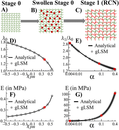
Fig. 1A–C depict the scheme for gel growth described in our analytical model3 for unconstrained growth. In Stage 0, the primary (parent) gel is placed into a liquid composed of monomer and cross-linkers. This “monomer solution” can diffuse into the gel and cause it to swell (Fig. 1B). As the last step of Stage 0, this swollen gel equilibrates to reach its final size.
Stage 1 starts with the polymerization of the monomers adsorbed at the end of Stage 0. This polymerization leads to the formation of the secondary chains, which then cross-link to form a distinct, new network within the primary gel. At this point, the secondary chains can undergo exchange reactions with the primary gel to form a random copolymer network (RCN). Note that during the latter crosslinking process, we calculate the amount of sol (a mixture of disconnected, small gel-like pieces and uncross-linked chains) and remove them from our final RCN (Fig. 1C).
In the last step of Stage 1, the RCN is placed in a bath that is identical to the initial monomer solution as in Fig. 1B. The RCN gel swells as monomeric units from the solution are incorporated into the network. This swollen gel now forms the medium for Stage 2 and so on.
Alternatively, we also carried out an analytical model that forms a different network, namely, the interpenetrating polymer network (IPN).3 Using our analytical model,3 we found that chains in the primary network within the swollen IPN (Stage 1) are relatively stretched. This stretching is entropically unfavorable and hinders uptake of monomer and cross-linker during further stages of growth. In contrast, the chain-exchange reactions between the primary (green) and secondary (red) networks (Fig. 1) relieve the tension from chain stretching. In addition, the exchange reaction leads to the formation of a considerable quantity of sol and hence, the RCN remains soft. As a result, the RCN provides the distinct advantage that the gel network can grow multiple times.3 Consequently, we focus on the RCNs in the following studies.
Using our computational gLSM,7–10 we examine gel growth at hard surfaces, and within a soft matrix. These situations mimic the constraints in biological environments and the confining walls in manmade devices. Consequently, the findings can provide insight into the feedback between local mechanical stresses and the evolving structure in biological morphogenesis, and yield guidelines for adapting morphogenesis to fabricate materials where form is dynamically fashioned for optimal functionality.
It is important to note that schemes other than the ones cited above have led to successful gel growth.11–16 For example, researchers embedded photo-active iniferter groups into the parent gel. With the application of light, the iniferters draw on monomers and cross-linkers from the surrounding solution to initiate a photo-controlled radical polymerization (photo-CRP) and thereby grow a “child” within the parent network.11 Researchers also harnessed structurally tailored and engineered macromolecular (STEM) gels as a foundation for synthesizing growing gels.12–14 The system is comprised of a primary cross-linked “scaffold” containing latent active sites (inimers), which are used to initiate the polymerization and incorporation of the secondary chains in the initial scaffold. The STEM gel properties and functionality can be modified through these secondary chains (or the controlled attachment of organic molecules, proteins, or nanoparticles), which differentiate the grown gel from the initial scaffolds.
Below, we detail the governing equations in the gLSM and validate the model by comparison with results obtained from the analytical theory.
II. Methodology
In these simulations, a gel is represented by a set of hexahedral elements so that their vertices form a lattice, and the lattice nodes move due to elastic and osmotic forces from the adjacent elements. To model the process of gel growth in successive stages, we utilize our theoretical methodology that was formulated in ref. 3 Below, we describe the theoretical model, and then describe the incorporation of the theoretical framework into the gel lattice spring model (gLSM) for computer simulations. The primary network is characterized by the cross-link density, c0, and the polymer volume fraction in the un-deformed state, ϕ0. The un-deformed primary network is then swollen by immersing in a bath containing the secondary monomer and cross-linker. The degree of swelling of the primary un-deformed gel in the monomer solution (before polymerization and cross-linking) at equilibrium is denoted λ0. Note, λ0 = (V0/Vini)1/3, where V0 is the volume of swollen primary gel and Vini is the volume of the as-prepared (un-deformed) primary gel. This degree of swelling characterizes the growth of the Stage 0 gel. The number fraction of cross-linkers in the imbibed secondary monomers is given by α. When equilibrated, the size of the swollen primary gel is fixed, and the absorbed monomeric units undergo a reversible chain-growth polymerization reaction, and the resulting polymer chains exhibit the Flory molecular weight distribution (MWD).17 The polymer chains further undergo simultaneous cross-linking and inter-chain exchange with the primary polymer network to form Stage 1 random copolymer network (RCN). After removal of the sol fraction, the sample is swollen in the same monomer solution as before, and the stage of growth is considered to be complete. The degree of swelling given by λ1 = (V1/Vini)1/3, where V1 is the gel sample volume after the first stage of growth, characterizes growth of the gel during Stage 1.For the primary polymer network, the equilibrium degree of swelling in the secondary monomer solution is determined by the balance of elastic and osmotic forces. The total elastic stress of the equilibrated sample, σtot, is balanced by the Flory–Huggins osmotic pressure due to the monomers, πFH(ϕ):
| σtot = πFH(ϕ) | (1) |
The Flory–Huggins osmotic pressure is given by
| πFH(ϕ) = −[ϕ + ln(1 − ϕ) + χpmϕ2] | (2) |
Below, we briefly discuss the change in the stress balance calculations for the growth of RCN networks. In the process of simultaneous cross-linking and inter-chain exchange, the network exchange leads to the formation of a single network of cross-linked random copolymers consisting of the primary and secondary monomeric units. As a result, there is only one contribution to the elastic stress σtot characterized by the single cross-link density c(RCN)1. The sol fraction, S(RCN)1, removed from the network also contains the primary and secondary monomeric units. The calculations of c(RCN)1 and S(RCN)1 are discussed in the ESI.†
After the first stage of growth, the size of the Stage 1 RCN gel is determined by the following equation for the force balance
| σel(c(RCN)1, λ/λ0) = πFH[ϕ(1)(λ), ψ(1)(λ)] | (3) |
| πFH(ϕ, ψ) = −[ϕ + ψ + ln(1 − ϕ − ψ) + χpmϕ2] | (4) |
The incorporation of the above theory into the computational gLSM approach is described in the ESI.† Using the results of the gLSM, we plot the growth of the initial parent network (in Fig. 1D) and the equilibrium Young's modulus (Fig. 1F). The latter values depend on the Flory–Huggins parameter χpm, which describes interactions between the primary and secondary monomers. The value of χpm affects the amount of secondary units that are adsorbed. Using the value of χpm = 0.33, we characterize how the degree of swelling (Fig. 1E) and the equilibrium Young's modulus (Fig. 1G) for Stage 1 RCN changes as a function of the cross-linker fraction, α. Note that the gLSM results reproduces the analytical results obtained from the above eqn (1)–(4).
III. Results and discussion
The number of hexahedral elements along the directions X, Y, Z are given by LX, LY, and LZ, respectively. To validate our computational approach, we compare results obtained from the theory and gLSM simulations with a sample size of LX × LY × LZ (where LX = LY = LZ = 3) for the degree of swelling of the RCN at Stages 0 and 1. In Fig. 1C and D the solid black circles representing results from the gLSM simulations lie on top of the line obtained from the analytical calculations. The plots show that the gLSM results are in quantitative agreement with results from the analytical model.The parameters used in the gLSM simulations representing the gel properties of the Stage 0 gel are taken from3,9ϕ0 = 0.139 and c0 = 1.3 × 10⁻³. The spatial discretization of the undeformed (initial) sample is chosen as uniform along the X, Y, Z directions, and is given by dX = dY = dZ = 1, the time step of the simulations is chosen to be9 dt = 0.001, and the dimensionless kinetic coefficient was set at Λ0 = 1000. For the polymerization and cross-linking of the Stage 1 gel, we use the rate of polymerization to depolymerization to be γ+/γ− = 5 × 10⁶. Three distinct values of the fraction of cross-linker were used for different simulation scenarios: α = 0.004, 0.1, 0.4. We explicitly state the value of α where the simulation results are described. The results are presented in dimensionless simulation units. The units of modulus (stress) in physical units is given by σ0 = kBT/vs = 135.33 MPa where kB is the Boltzmann's constant, T is chosen to be 20 °C and vs = 0.018 is the molar volume of water. The unit of length and time is chosen such that9,21D = l02/t0 = 2 × 10⁻⁵ cm2 s−1, which gives l0 = 40 μm and t0 = 1 s.
The simulations proceed through the following steps. The Stage 0 sample is prepared by swelling the parent gel in a bath containing a monomer solution. The gLSM equations for Stage 0 are used to model the dynamic swelling of the sample until it reaches the final equilibrium state. The volume fraction of absorbed monomers, ψ, at this swollen, equilibrated state are then utilized to build the Stage 1 RCN network by polymerizing and cross-linking the ψ monomers (see equations in Sections S1 and S2 in the ESI†). Equations described in Section S3 (ESI†) is then used to simulate the behavior of the Stage 1 RCN network after the chain-exchange and removal of the sol fraction have occurred. Note that the gel equations are not evolved during this process of polymerization and cross-linking.
Once the Stage 1 RCN is formed, we utilize the equations mentioned in Section S3 in the ESI† to model the dynamical evolution of the Stage 1 gel until it reaches final equilibrium configuration. Specifically, the nodes are evolved using eqn (S3.6) (ESI†) while the forces are calculated using (see eqn (S3.19) and (S3.22), ESI†) and the mobility is evaluated using (see eqn (S3.23), ESI†). When only a fraction of the gel elements in Stage 0 undergo polymerization and cross-linking, the elements contributing to the Stage 1 RCN gel are evolved with the relative deformation tensors and the RCN related dynamical equations, while the elements without the RCN are evolved with the equations of the Stage 0 gel.
In modeling confined samples, we utilized the Morse potential to represent the repulsion between the hard walls and freely swelling gel nodes. Specifically, we utilized the calculation of node-to-node forces as given in ref. 22. The parameters used for the Morse potential are provided in the ESI.†
Below, we use this computational approach to compare the systems’ behavior when gels of different sizes and shapes grow in the absence or presence of bordering walls. In particular, we determine the effects of confinement on systems of increasing complexity: thin, square samples; rectangular layers; mechanically patterned thin gels; and thicker gels bounded by hard or soft walls. As we show below for thin gels, growth to Stage 1 can trap the formation of non-equilibrium structures, even when shape-defining walls are removed. Analogous to biological morphogenesis,15,23–29 the stresses are seen to play a vital role in directing the process of growth.
A. Confinement between hard surfaces: Stage 0 for a square gel layer
We consider a square flat gel in the as-prepared un-deformed state with the degree of swelling λini = 1. The sample size is 35 × 35 × 2 elements in X, Y, Z directions, respectively. At Stage 0 in the absence of confinement, the swollen primary gel also is a square flat layer with the degree of swelling λ0 = 1.3187 as the solvent is uniformly distributed in the sample.The shape of the Stage 0 gel changes drastically if before swelling, we introduce two hard walls at the faces X = 0 and Y = 0 of the as-prepared primary gel. We require gel nodes on these surfaces to remain fixed in space, and thereby prohibiting their motion. In the course of swelling, these two immobile gel surfaces cause a spatially non-uniform distribution of solvent. The degree of swelling close to the constrained surfaces is less than that at the free boundaries, which are in contact with the solvent, and hence, the gel loses its initial square shape.
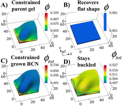
The constrained surfaces generate an uneven distribution of stress within the swelling gel. As a result, the parent gel morphs into a buckled structure (Fig. 2A) to diminish stress in the material. Such buckling has been predicted and observed when swollen polymer gels are confined by a hard surface30–36 or purposefully planned through site-specific swelling.37 The colors in the plot indicate the local volume fraction of polymer ϕ, which is an effective measure of stress in the sample (high stress at high values of ϕ). The polymer volume fraction (and stress) is highest at the bound edges since the gel anchored at the wall is constrained from expanding. The center of the sample shows the lowest ϕ, as seen in Fig. 2A.
The structural evolution of the confined parent gel goes through an intermediate, kinetically unstable state where any small perturbation pushes the system into the buckled structure (Fig. S2, ESI†). If the confining walls are now removed from the Stage 0 morphed sample, the primary gel eventually returns to a relaxed flat state, which has a lower free energy than the buckled structure (Fig. 2B).
If now unconstrained growth occurs on a free, flat parent, the resulting Stage 1 layer would also assume a flat geometry, i.e., the growth occurs without a shape change (Fig. S3, ESI†). The flat layers can still be altered by changing the cross-link density in the sample. An increase in the cross-link density leads to a decrease in the degree of swelling and in the mesh size within the gel (Fig. S3, ESI†).
B. Confinement between hard surfaces: Stage 1
With the walls remaining fixed in place, we initiate Stage 1 growth by polymerizing and cross-linking the species that diffused into the parent gel during its swelling and buckling. The fraction of cross-linker was chosen to be α = 0.4. After the chain-exchange and removal of the sol fraction, the Stage 1 RCN sample (Fig. 2C) effectively replicates the form of the confined parent network. When the walls are removed at this stage, however, the gel does not relax back to a flat configuration but remains in the buckled state (Fig. 2D). The growth fixes an energetically unfavorable, deformed shape into a stable configuration. The shape of the flat parent gel can be refashioned into other geometries with the introduction of different siding (e.g., walls on three or all four sides). While the free parent gel is mutable in this manner, the progeny is not.The distortion induced in the confined parent gel is more pronounced in the progeny, as indicated by Fig. 3A. The maximum height in the diagonal cross-section for the Stage 1 (confined or released) is 1.45 times greater than the height for the parent. Thus, the shape of the confined parent gel templates and amplifies the morphology of subsequent growth. In a manner of speaking, the system encompasses “memory” since the buckled shape in Stage 0 under confinement is stored in the system and recalled to regulate the next stage of development during gel growth.
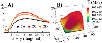 | ||
| Fig. 3 (A) The displacement dz in the vertical direction of the middle layer of the gel elements with respect to a flat reference state where the mid-layer has the value of Z = 1.0 for the Stage 0 gel, and Z = 1.3187 for the Stage 1 gel as a function of the index of the diagonal gel nodes. (B) The Young's modulus E of the Stage 1 gel after release of constraints for the sample shown in Fig. 2D. | ||
For the relaxed Stage 1 RCN grown under confinement, the distribution of solvent in the sample (Fig. 2D) affects the variation in local mechanical properties, i.e., the Young's modulus shown in Fig. 3B (see ESI† Fig. S4).
C. Growth in rectangular samples
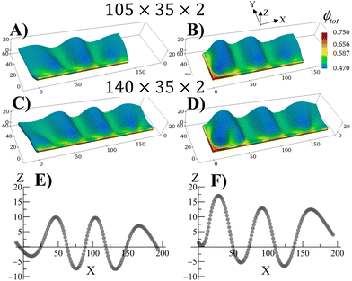
The swollen pinned square gel displays just one prominent buckle, which is stabilized during the growth process (Fig. 2). It is known that long strips of gel that are attached to a hard surface can exhibit a periodic buckling pattern when swollen.30,33,34,38 The same mechanism that produced the buckling instability in Fig. 2 can be used to modulate the shape of grown RCN gels by varying aspect ratio of the primary gel and boundary constraints. To demonstrate the latter behavior, we consider rectangular primary gel samples, which are three or four times longer than the square gel in Fig. 2. During Stage 0, the samples swell in the monomer solution with no boundary constraints. After polymerization, cross linking and chain-exchange, the boundary constraints are applied, and the sample containing the grown RCN are put back into the monomer solution to complete Stage 1 of growth. The fraction of cross-linker was chosen to α = 0.1.Fig. 4 shows Stage 1 grown rectangular RCN samples, where the primary parent gels are three (Fig. 4A and C) and four (Fig. 4B and D) times longer than that for the square gel in Fig. 2. The samples presented in Fig. 4 are still attached to the confining walls. For the cases shown in Fig. 4A and B, the primary gels were attached to a hard surface along the long axis at Y = 0. Fig. 4A and B show that the Stage 1 grown RCN gels exhibit distinct buckles, with the longer sample in Fig. 4B displaying three such waves. As seen in other example of confined swollen gels,30,31 the buckling pattern has a characteristic wave length as evident from Fig. 4E,30 which shows the Z coordinate of nodes along the top, unconstrained edge of the sample in Fig. 4B.
The introduction of additional confining wall at X = 0 leads to a slightly different bucking patterns in Stage 1 grown RCN gels as shown in Fig. 4C and D. At lengths further away from the additional confining surface, however, the influence of this wall is diminished, and the system again exhibits regular periodicity as seen in Fig. 4E.
The RCNs in Fig. 4 are grown from a flat layer at Stage 0, and the constraints are only introduced in the Stage 1 system. If the constraints are subsequently removed, the grown RCN will relax back to the flat shape, effectively recalling the shape of the parent (see Movie S1, ESI†). Conversely, if the parent gel is attached to a hard surface and buckles during Stage 0, then the grown RCN retains the periodically buckled pattern when the constraints are released (see Movie S2, ESI†). Again, the grown RCN shows “memory” effects as the system replicates the before-growth structure of the parent.
D. Structural patterning during Stage 1 growth
Just as the pinning of walls affects the mechanical behavior (see Fig. 2), the sample can be structurally patterned to tailor the buckling patterns.37 Thus, the structural patterning and concomitant growth can be harnessed to create materials with specified morphology and properties. In living systems, morphological patterns are generally formed in conjunction with the growth process, i.e., patterning and growth occur simultaneously. One form of structural patterning involves spatial variations between hard and soft tissue. In the cases described below, the fraction of cross-linkers α in Stage 1 RCN is set higher in one region than the other and the entire sample experiences Stage 1 growth. In this way, structural patterning and growth of the gel are occurring simultaneously. Thus, the gels described here, capture the scenario when growth and development evolve in a dynamically changing landscape, where the stiff region affects the morphology of the soft domains, which in turn influence the shape of the hard region. The findings can reveal how the two biomimetic processes (growth and morphological evolution) can be dynamically interconnected to tailor the design of synthetic structural materials.To facilitate comparisons with the examples in Section III.B, we focus on square-shaped gels that are bound by two hard walls. Specifically, we assume that the parent gels swell freely during Stage 0 so the RCN gels are formed in flat samples. Then, the sample faces along X = 0 and Y = 0 are fixed to hard surfaces, and the RCN gels swell to complete Stage 1 of growth.
After Stage 0, the secondary monomers are distributed uniformly throughout the parent network. We assume, however, that during cross-linking of the secondary polymers at Stage 1, one half of a sample encompasses four times the amount of cross-linker than the rest of the sample. Experimentally, this form of patterning could be achieved through photo-induced polymerization and cross-linking, where one half of the sample is irradiated for a longer period than the other.1,2,4
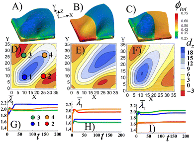
As a point of reference, Fig. 5A shows the Stage 1 RCN gel with a uniform distribution of the secondary cross-links for α = 0.1 that is bound by the X = 0 and Y = 0 walls. The colors indicate the spatial distribution of the total volume fraction of polymer in gel the ϕtot. Similar to Fig. 2C, the confinement introduces bucking along diagonal of the sample. The bucking pattern is symmetric, as evident in Fig. 5D which shows the nodal displacements in the Z direction, dz, in the middle plane of the gel sample. Fig. 5D also shows that the gel is buckled upward along the diagonal (blue corresponds to positive dz), whereas the areas in the upper left and lower right corners are buckled downward (red corresponds to negative dz). To characterize the elastic strain in different parts of the sample, in Fig. 5G we plot the average strain ![[small lambda, Greek, macron]](https://www.rsc.org/images/entities/i_char_e0cc.gif) 1 (see the ESI†) as a function of time t in the four quadrants of the sample, as marked by circles in Fig. 5D. The highest strain is observed in quadrant 1, which experiences the effects of both walls (see blue line in Fig. 5G). The plots also indicate that buckling occurs directly after the initial swelling of the RCN gel during Stage 1 of growth, as indicated by the peaks in the curves just after t = 0 (Fig. 5G).
1 (see the ESI†) as a function of time t in the four quadrants of the sample, as marked by circles in Fig. 5D. The highest strain is observed in quadrant 1, which experiences the effects of both walls (see blue line in Fig. 5G). The plots also indicate that buckling occurs directly after the initial swelling of the RCN gel during Stage 1 of growth, as indicated by the peaks in the curves just after t = 0 (Fig. 5G).
In Fig. 5B, the left half of the Stage 1 RCN gel encompasses four times more secondary cross-links, α = 0.4, than the right half, α = 0.1 As a result, the left half is stiffer and less swollen than the right one. The buckling pattern becomes asymmetric relative to the central diagonal of the sample (Fig. 5E). The out-of-plane displacements dz of the stiffer part are lower in the bottom left corner, which is most perturbed by the confining walls, than those in Fig. 5D. The highest displacements, both positive and negative, are now shifted to the right, (relative to Fig. 5) and are localized in the softer part of the sample (Fig. 5E). Correspondingly, the average strain ![[small lambda, Greek, macron]](https://www.rsc.org/images/entities/i_char_e0cc.gif) 1 is greater in the softer quadrants (2 and 4) than stiffer ones (1 and 3) as seen in Fig. 5H.
1 is greater in the softer quadrants (2 and 4) than stiffer ones (1 and 3) as seen in Fig. 5H.
When the softer and stiffer parts in Stage1 RCN are switched in position (Fig. 5C), the qualitative behavior is quite similar to that observed in Fig. 5B. Namely, the soft part exhibits higher out-of-plane displacements (Fig. 5F) and greater average strains (Fig. 5I) than the stiffer part of the sample. Now, however, the peak in the buckle height is shifted to quadrant 1 (as opposed to being in quadrant 4 in Fig. 5B).
Relative to the structure in Fig. 5A, the patterned, mechanically stiffer regions in Fig. 5B and C effectively “iron out” the wrinkles in those areas, and the wrinkles are shifted to the softer domains of the gel. Notably, forming layers that encompass both well-defined corrugations and flat domains is useful in a range of applications,39 but is difficult to achieve. For example, this form of patterning might require two separate rolling devices (as in the case of thin metallic sheets), one roller to form the flat surface and another to introduce the corrugations.40 These simulation results indicate a means of controllably “growing” analogous patterned, heterogeneous surfaces.
When the gel systems in Fig. 5 are detached from the hard walls, the parent gel for the case in Fig. 5A relaxes to the flat shape, while the parent gels for the cases shown in Fig. 5B and C reflect the patterning introduced at Stage 0 and assume a double roll shape41 (see ESI,† Fig. S5) Additionally, we show the final equilibrium shapes obtained for different boundary constraints – the swelling of the flat grown RCN gel when three sides of the gel are constrained by walls, and when all four sides are constrained (see ESI,† Fig. S6).
E. Growth of blocks in layered structures
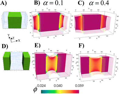
The ability to grow micro- to macroscopic gels that bridge separated surfaces or encase distinct regions addresses a number of technological challenges, from healing damaged devices, to creating a new connection between individual units or providing a protective coating for exposed surfaces. The schematics in Fig. 6A and D illustrate the two different cases considered here; green marks the regions in the parent gel where growth of the RCN gel takes place. As before, the parent gel is swollen in monomer solution (Stage 0). Stage 1 growth is initiated by selective polymerization and cross-linking in the specified areas (a process that can be experimentally achieved by using a photomask with the appropriate shape) and the subsequent chain-exchange.The formed RCN gel can be softer or stiffer depending on the fraction of cross-linkers α in the solution. To complete Stage 1, the entire gel sample is placed in the initial solution to swell the material to equilibrium. Fig. 6B and E show cross-sections of the resulting samples with softer RCN at α = 0.1; Fig. 6C and F correspond to Stage 1 samples with stiffer RCN at α = 0.4. The color bar indicates the local volume fraction of polymer, with red marking the highest and blue indicating the lowest. As seen from the figures, the total volume fraction of polymer in the stiffer grown RCNs is much higher that than in the softer primary gel, specifically,ϕtot = 0.281 for α = 0.1 and ϕtot = 0.512 for α = 0.4.
Notably, the relative location of the growing material is a determining factor in the final morphology of the system (Fig. 6). Whether the growing material at the edges is soft or hard, the central grown area resembles a solid brick, whereas the outer primary gels appear “pinched” as these regions respond to stresses imposed by the grown inner domains. For the parameter values used for these simulations, the Young's modulus of the grown RCN-containing layers is approximately three orders of magnitude higher than Young's modulus of the primary gel matrix. Specifically, Young's modulus of the matrix is 0.33 MPa, whereas the maximum value of Young's modulus of the grown softer gel is 20.8 MPa and that for the grown stiffer RCN gel is 103.1 MPa.
Given the bio-mimetic nature of our approach, the simulations provide guidelines for growing materials with a cartilage-like or even a bone-like mechanical properties within soft “tissue” of a polymer gel. More generally, these studies reveal how the relative growth of the softer or harder domains affects the morphology of neighboring layers. Moreover, the non-growing and growing parts can be viewed as having different growth rates, with the rate in the “non-growing” region being significantly slower than the rapid rate in the growing part. Thus, the simulations can also be used to expose morphological changes in neighboring areas that have substantially different rates of growth.
F. Growth of an inclusion
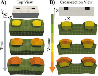
To cover the range of potential mechanical heterogeneities in the grown materials, we simulated the system's behavior when the spatially localized “seeds” are embedded near the top of a flat, free-standing, swollen gel.4 In this context, the word “seeds” refers to localized, embedded regions that selectively undergo grown. The initial placement of the seeds in a parent gel is indicated by the black squares in Fig. 7. This particular case allows us to investigate growth of a soft material embedded in a soft, deformable network.The cross-link density in the parents (Stage 0) and embedded seeds are initially set to the same value, c0. The entire sample (Stage 0) is immersed in solution and swollen by the uptake of monomer and cross-linkers. Stage 1 growth occurs solely within the seeds where the fraction of crosslinks is α = 0.004.
As seen in Fig. 7, the subsequent increase in the polymer concentration and volume in the seed region causes the newly formed network to protrude from the surface (above the black squares). The color bar indicates that the new layer bulges not only upward, but also outward, maximizing the volume available for growth and counteracting the restrictive forces from the bounding, non-growing domain (in green). The less cross-linked parent layer is also deformed by the localized expansion of the seeds. These findings and structural features show qualitative agreement with experiments1,2,4 where photomasks were used to selectively irradiate only the seed regions, localizing the optically catalyzed polymerization, cross-linking and resultant growth solely to these illuminated regions. Additionally for comparison, we show the swelling of an uniformly cross-linked primary Stage 0 gel prepared in the shape of the grown RCN 1 gel (see ESI† Fig. S7).
IV. Conclusions
These studies were inspired by the growth of biological tissue, which typically evolves in the presence of neighboring walls due to the spatial crowding characteristic of the local environment. To probe the effect of confining walls on the growth and structural evolution of biomimetic materials, we developed a computational approach to model the growth of polymer gels in the absence and presence of such neighboring surfaces. The initial parent gel was immersed and swollen in a liquid monomer, thereby forming Stage 0 growth. We showed that confinement plays a critical role on the Stage 0 sample and subsequent growth of the random copolymer network (RCN) from this parent. In particular, if the RCN is grown on a flat Stage 0 surface, and then confined by walls, this RCN will buckle due to the competition between the constraining forces from the wall and the elastic and osmotic forces in a swelling network. If the confining walls are removed, the RCN returns to the initial flat structure of the Stage 0 parent.If the Stage 0 is confined, it undergoes buckling due the competition of the latter forces. When Stage 1 growth occurs in this deformed body of parent gel, the underlying layer effectively templates the subsequent growth of the RCN. If the walls are removed at this stage, the RCN remains buckled. If, however, the RCN grows on a flat parent and is subsequently confined, the resulting buckling disappears when the walls are removed at this stage. In essence, the RCN exhibits a “memory” effect; removal of the walls from the grown RCN returns the morphology of initial structure of the Stage 0 parent. In both cases, the Young's modulus of the RCN could be two orders of magnitude greater than that for the parent depending on the amount of cross-linker in the monomer bath.
When a thicker gel was grown between 3D walls, the Young's modulus of the grown RCN was three orders of magnitude greater than that for the parent material under elevated content of cross-linker in the bath. In the two cases considered here, the growing portion (shown in green in Fig. 6A and D) displayed a higher crosslink density than the non-growing material since cross-linking monomers were absorbed from the solution in the formation of the RCN. The high stress imposed by the more cross-linked harder gel causes the bounding, softer network to be “pinched” at the interfaces. If the growth occurs in the central block, then the ends become pinched and if the growth occurs at the outer pillars, the central domain becomes pinched. Hence, the location of the growing domain dictates the morphology of the entire slab. These results also show that selective localization of the growth provides a means to generate well-controlled structural heterogeneity in one sample. This mode of fabricating mechanically patterned, three-dimensional networks can potentially be more effective than binding together mechanically different components to form heterogeneous structures.
The scenario involving growth from a parent embedded within a soft gel also highlights useful design rules. Namely, localizing or arranging the growing seeds into appropriate patterns can permit new forms of additive manufacturing, where 3D printing can be augmented by purposeful designs that grow into the desired structures.
In the context of self-healing materials, the results suggest approaches for creating coatings that fill existing fissures. Additionally, if the container housing the materials system is sufficiently large to accommodate growth above, below and at the sides of the non-growing domains, then growth of the RCN provides protective coating to hinder further damage.
Overall, the finding provide bio-inspired guidelines for simultaneously fashioning the form and mechanics of synthetic materials. Much as the coupled control over mechanical and spatial variation is beneficial for biological functionality, such purposefully designed heterogeneous materials can exhibit new useful materials’ properties.
Conflicts of interest
There are no conflicts of interest to declare.Acknowledgements
ACB gratefully acknowledges support from DOE grant number DE-SC0005247 to support the work of S. B. and from DOE grant number DE-FG02-02ER45998 to support V. V. Y. This research was supported in part by the University of Pittsburgh Center for Research Computing through the resources provided. Specifically, this work used the H2P cluster, which is supported by NSF award number OAC-2117681.References
- X. Zhou, Y. Zheng, H. Zhang, L. Yang, Y. Cui, B. P. Krishnan, S. Dong, M. Aizenberg, X. Xiong, Y. Hu, J. Aizenberg and J. Cui, Nat. Commun., 2023, 14, 3302 CrossRef CAS PubMed.
- X. Xiong, S. Wang, L. Xue, H. Wang and J. Cui, ACS Appl. Mater. Interfaces, 2022, 14, 8473–8481 CrossRef CAS PubMed.
- R. Chatterjee, S. Biswas, V. V. Yashin, M. Aizenberg, J. Aizenberg and A. C. Balazs, Soft Matter, 2021, 17, 7177–7187 RSC.
- L. Xue, X. Xiong, B. P. Krishnan, F. Puza, S. Wang, Y. Zheng and J. Cui, Nat. Commun., 2020, 11, 963 CrossRef CAS.
- R. Takahashi, H. Miyazako, A. Tanaka, Y. Ueno and M. Yamaguchi, Lab Chip, 2021, 21, 1307–1317 RSC.
- C. Y. Li, D. Jiao, X. P. Hao, W. Hong, Q. Zheng and Z. L. Wu, Adv. Mater., 2023, 35, 2211802 CrossRef CAS.
- V. V. Yashin and A. C. Balazs, Science, 2006, 314, 798–801 CrossRef CAS.
- V. V. Yashin and A. C. Balazs, J. Chem. Phys., 2007, 126, 124707 CrossRef.
- O. Kuksenok, V. V. Yashin and A. C. Balazs, Phys. Rev. E: Stat., Nonlinear, Soft Matter Phys., 2008, 78, 041406 CrossRef PubMed.
- S. Biswas, V. V. Yashin and A. C. Balazs, Soft Matter, 2018, 14, 3361–3371 RSC.
- M. Chen, Y. Gu, A. Singh, M. Zhong, A. M. Jordan, S. Biswas, L. T. J. Korley, A. C. Balazs and J. A. Johnson, ACS Cent. Sci., 2017, 3, 124–134 CrossRef CAS.
- J. Cuthbert, T. Zhang, S. Biswas, M. Olszewski, S. Shanmugam, T. Fu, E. Gottlieb, T. Kowalewski, A. C. Balazs and K. Matyjaszewski, Macromolecules, 2018, 51, 9184–9191 CrossRef CAS.
- A. Beziau, A. Fortney, L. Fu, C. Nishiura, H. Wang, J. Cuthbert, E. Gottlieb, A. C. Balazs, T. Kowalewski and K. Matyjaszewski, Polymer, 2017, 126, 224–230 CrossRef CAS.
- J. Cuthbert, A. Beziau, E. Gottlieb, L. Fu, R. Yuan, A. C. Balazs, T. Kowalewski and K. Matyjaszewski, Macromolecules, 2018, 51, 3808–3817 CrossRef CAS.
- Q. Mu, K. Cui, Z. J. Wang, T. Matsuda, W. Cui, H. Kato, S. Namiki, T. Yamazaki, M. Frauenlob, T. Nonoyama, M. Tsuda, S. Tanaka, T. Nakajima and J. P. Gong, Nat. Commun., 2022, 13, 6213 CrossRef CAS.
- T. Matsuda, R. Kawakami, R. Namba, T. Nakajima and J. P. Gong, Science, 2019, 363, 504–508 CrossRef CAS.
- P. J. Flory, Principles of polymer chemistry, Cornell University Press, Ithaca, 1st edn, 1953 Search PubMed.
- T. L. Hill, An introduction to statistical thermodynamics, Dover, New York, 1986 Search PubMed.
- A. Onuki, Adv. Polym. Sci., 1993, 109, 63–121 CrossRef CAS.
- A. D. Drozdov, Finite Elasticity and Viscoelasticity, World Scientific, Singapore, 1996 Search PubMed.
- T. Zhang, V. V. Yashin and A. C. Balazs, Soft Matter, 2018, 14, 1822–1832 RSC.
- P. Wriggers, Computational contact mechanics, Springer-Verlag Berlin Heidelberg, Netherlands, 2nd edn, 2006 Search PubMed.
- A. Trushko, I. Di Meglio, A. Merzouki, C. Blanch-Mercader, S. Abuhattum, J. Guck, K. Alessandri, P. Nassoy, K. Kruse, B. Chopard and A. Roux, Dev. Cell, 2020, 54, 655–668 CrossRef CAS PubMed.
- W.-H. Xie, B. Li, Y. P. Cao and X. Q. Feng, J. Mech. Behav. Biomed. Mater., 2014, 29, 594–601 CrossRef.
- A. E. Shyer, T. Tallinen, N. L. Nerurkar, Z. Wei, E. S. Gil, D. L. Kaplan, C. J. Tabin and L. Mahadevan, Science, 2013, 342, 212–218 CrossRef CAS PubMed.
- T. Savin, N. A. Kurpios, A. E. Shyer, P. Florescu, H. Liang, L. Mahadevan and C. J. Tabin, Nature, 2011, 476, 57–62 CrossRef CAS PubMed.
- J. Yan, C. Fei, S. Mao, A. Moreau, N. S. Wingreen, A. Košmrlj, H. A. Stone and B. L. Bassler, eLife, 2019, 8, e43920 CrossRef.
- H. Liang and L. Mahadevan, Proc. Natl. Acad. Sci. U. S. A., 2009, 106, 22049–22054 CrossRef CAS PubMed.
- B. Schamberger, R. Ziege, K. Anselme, M. Ben Amar, M. Bykowski, A. P. G. Castro, A. Cipitria, R. A. Coles, R. Dimova, M. Eder, S. Ehrig, L. M. Escudero, M. E. Evans, P. R. Fernandes, P. Fratzl, L. Geris, N. Gierlinger, E. Hannezo, A. Iglič, J. J. K. Kirkensgaard, P. Kollmannsberger, Ł. Kowalewska, N. A. Kurniawan, I. Papantoniou, L. Pieuchot, T. H. V. Pires, L. D. Renner, A. O. Sageman-Furnas, G. E. Schröder-Turk, A. Sengupta, V. R. Sharma, A. Tagua, C. Tomba, X. Trepat, S. L. Waters, E. F. Yeo, A. Roschger, C. M. Bidan and J. W. C. Dunlop, Adv. Mater., 2023, 35, 2206110 CrossRef CAS PubMed.
- T. Mora and A. Boudaoud, Eur. Phys. J. E, 2006, 20, 119–124 CrossRef CAS.
- A. G. Fletcher, M. Osterfield, R. E. Baker and S. Y. Shvartsman, Biophys. J., 2014, 106, 2291–2304 CrossRef CAS.
- H. Zhang and Y. Hu, J. Mech. Phys. Solids, 2023, 172, 105155 CrossRef CAS.
- S. J. DuPont Jr., R. S. Cates, P. G. Stroot and R. Toomey, Soft Matter, 2010, 6, 3876 RSC.
- B. Li, Y. P. Cao, X. Q. Feng and H. Gao, Soft Matter, 2012, 8, 5728 RSC.
- Q. Wang, Y. Yin, H. Xie, J. Liu, W. Yang, P. Chen and Q. Zhang, Soft Matter, 2011, 7, 2888–2894 RSC.
- D. Vella, Nat. Rev. Phys., 2019, 1, 425–436 CrossRef.
- Z. J. Wang, W. Hong, Z. L. Wu and Q. Zheng, Angew. Chem., Int. Ed., 2017, 56, 15974–15978 CrossRef CAS.
- J. Zhang, X. Zhao, Z. Suo and H. Jiang, J. Appl. Phys., 2009, 105, 93522 CrossRef.
- T. Li, K. Hu, X. Ma, W. Zhang, J. Yin and X. Jiang, Adv. Mater., 2020, 32, 1906712 CrossRef CAS.
- T. Wang, Y. Wang, L. Bian and Q. Huang, Mater. Sci. Eng., A, 2019, 765, 138318 CrossRef CAS.
- O. Oshri, S. Biswas and A. C. Balazs, Phys. Rev. E, 2019, 99, 033003 CrossRef CAS.
Footnote |
| † Electronic supplementary information (ESI) available. See DOI: https://doi.org/10.1039/d3mh00983a |
| This journal is © The Royal Society of Chemistry 2024 |

