 Open Access Article
Creative Commons Attribution 3.0 Unported Licence
Thermoelectric materials for space explorations
Dulyawich
Palaporn
 a,
Sora-at
Tanusilp
 *b,
Yifan
Sun
 c,
Supree
Pinitsoontorn
 ad and
Ken
Kurosaki
 *c
*c
aDepartment of Physics, Faculty of Science, Khon Kaen University, Khon Kaen 40002, Thailand
bFaculty of Engineering, Khon Kaen University, Khon Kaen 40002, Thailand. E-mail: sorata@kku.ac.th
cInstitute for Integrated Radiation and Nuclear Science, Kyoto University, 2, Asashiro-Nishi, Kumatori, Sennan-gun, Osaka 590-0494, Japan. E-mail: kurosaki.ken.6n@kyoto-u.ac.jp
dInstitution of Nanomaterials Research and Innovation for Energy, Faculty of Science, Khon Kaen University, Khon Kaen 40002, Thailand
First published on 29th May 2024
Abstract
This comprehensive review examines the historical development of radioisotope thermoelectric generators (RTGs) over the last fifty years and anticipates future missions, providing insights into the meticulous selection of radioisotope heat sources and thermoelectric (TE) materials throughout the generations of RTGs. It analyzes the TE properties of conventional materials and investigates strategies to improve them, with a special emphasis on a dual-principle approach to increase the dimensionless figure of merit (zT). As advancements in TE materials and RTG design continue, the focus extends beyond TE properties to include other critical factors for effective RTG integration such as durability, safety, and weight.
1. Introduction
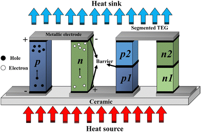
The thermoelectric (TE) effect, characterized by the Seebeck and Peltier effects, facilitates the efficient conversion of heat into electrical energy and vice versa. This principle underlies the operation of diverse TE devices, commonly referred to as thermoelectric generators (TEGs), which serve as promising alternatives for energy generation. A standard TEG module consists of TE couples made of p- and n-type materials, interconnected by metallic electrodes arranged in series in a π-shaped configuration, as illustrated in Fig. 1. Ceramic plates are used to establish thermal contact between the electrodes and the hot (heat source) and cold (heat sink) sides. This design ensures longitudinal heat transfer within the TE material, while the electrical current flows perpendicularly to the direction of heat flow. Additionally, the integration of diffusion barriers prevents any inter-material reactions, stabilizing contact resistance and extending the lifespan of TEGs.The traditional module design, as shown in Fig. 1 (left), is widely used due to its straightforward design and ease of assembly, contributing to its low production costs. Nevertheless, the demanding requirements of space mission necessitates high efficiency and a long service life, leading to the development of a segmented design, as shown in Fig. 1 (right). This innovative design can outperform the traditional modules through the proper selection and matching of TE materials. Additionally, it also allows for the alignment of thermal expansion coefficients between p- and n-type materials to reduce torque damage. However, the segmented design is more complicated to assemble compared to traditional modules, which increases production costs and requires comprehensive stability testing, potentially over many years, before operation.
Some of the main applications of TEGs lie in serving as primary electric power sources in specialized scenarios, including deep space exploration, planetary surface missions, orbital endeavors, and other isolated environments.1 Due to their ability to generate electricity without any moving parts, TEGs not only provide a noiseless and vibration-free operating environment but also avoid damaging nearby systems throughout its extended service life.2
In 1954, the first application of TEGs to convert heat from the polonium-210 (210Po) into electricity using chrome-constantan thermocouples marked the inception of the radioisotope thermoelectric generator (RTG).3,4 In the 1960s, the National Aeronautics and Space Administration (NASA) introduced TEGs as a power source for its space program. Subsequently, RTGs have been deployed in various NASA space missions, including Galileo (1989, Jupiter), Ulysses (1990, solar mission), Cassini (1997, Saturn), New Horizons (2006, deep space mission), and Curiosity (2012, Mars).5,6 These missions utilized RTGs with Plutonium-238 (238Pu) as the heat source, employing tellurium (Te) alloys within moderate temperature ranges (500–800 K) and silicon–germanium (SiGe) alloys at higher temperatures (>800 K). In contrast, the European space program opted for americium-241 (241Am) instead of plutonium-238 (238Pu) due to concerns about the latter's scarcity and price.7–9
The design of RTGs requires careful consideration of various factors, including preventing device degradation during extended service missions,10 minimizing the total weight of the devices,11 and using segmented TEGs to optimize output power and ensure proper operation under specific circumstances.12–14 Furthermore, a critical aspect of RTG design is the accommodation of the TE materials for energy generation. For example, RTGs utilizing tellurium alloys must operate under an inert gas atmosphere to prevent the sublimation and oxidation of tellurium. In contrast, the SiGe based RTGs can operate without a cover gas at high temperatures (approximately 1275 K) in the space environment. Nevertheless, the oxidation of other component, typically molybdenum, presents a significant challenge to the long-term use of conventional SiGe based RTGs, requiring them to be sealed at launch on the planetary surface.10 Given the important role of TE materials in the development of RTGs, this review presents an overview of the evolution of TE materials used in RTGs. Additionally, we explore and propose novel TE materials as promising candidates for advancing the next generation of RTGs.
2. The radioisotope thermoelectric generator (RTG)
As shown in Fig. 2, the primary components of an RTG consist of two main parts: (1) the heat source, which houses the radioisotope at the core or center of the module, and (2) the TEGs installed around the heat sources.15 The TEGs are separated from the heat source with insulation to protect the outer components from reactions and radiation emitted by the isotope. The design and size of RTGs are determined based on mission requirements, including power consumption and mission duration. In addition, to facilitate operations at high temperatures, certain supporting components, such as cooling systems—referred to as fins—and inert gas are employed to release excess heat from the TEGs and protect the materials from oxidation.10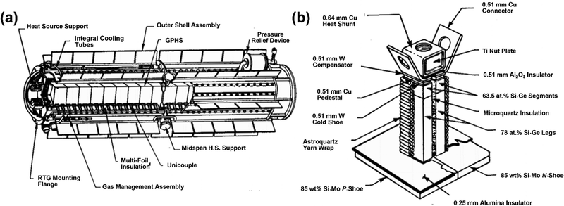 | ||
| Fig. 2 (a) Illustration of a conventional RTG configuration, featuring a length of 114 cm and a diameter of 42.2 cm. The general-purpose heat source (GPHS) is located in the center of module, surrounded by TE unicouples. (b) Detailed illustration of the TE unicouple installed around the heat source. This figure is redrawn by the authors, based on the original figure.15 | ||
2.1. The radioisotope heat source (RHS)
Over the 1300 types of radioisotopes produced from nuclear fission reactors and particle accelerators,16 approximately 100 are considered suitable for use as the heat source in RTGs. Given the prolonged service time of RTGs, ranging from 100 days to 100 years, the selected isotopes must meet specific criteria, including an output power requirement exceeding 0.1 W(thermal) g−1. Notably, 238Pu (0.39 W g−1), 250Cm (2.27 W g−1), 90Sr (0.22 W g−1), and 241Am (0.1 W g−1) are identified as the most promising candidates. Table 1 provides a summary of the power density (W g−1), half-life, and emission modes of these candidates.16| Radioisotope | Chemical forms used in RTG | Specific heat power (W g−1) | Half-life (year) | Emission mode |
|---|---|---|---|---|
| 238Pu | PuO2 | 0.39 | 87.74 | α |
| 244Cm | CmO2 | 2.27 | 18.11 | α |
| 90Sr | SrTiO2 | 0.22 | 28.00 | β |
| 241Am | AmO2 | 0.1 | 432 | α |
As illustrated in Table 1, 244Cm boasts the highest thermal power output among the isotope candidates but suffers from a short half-life, with its specific heat power (W g−1) halved every 18 years. In contrast, 90Sr, which has a slightly longer half-life of 28 years, requires thicker shielding to protect the outer system from β-rays, thereby increasing the RTG's total weight and cost. 238Pu achieves a balance by offering both a long half-life and high specific heat power from its alpha decay and is traditionally used in RTGs in the form of pure plutonium oxide (PuO2).16 However, driven by concerns regarding scarcity and cost of 238Pu, the European space program has opted to use 241Am, despite its lower thermal power output compared to other isotopes. This shift from 238Pu to 241Am is part of the European Space Agency (ESA) program since 2009 to develop new types of TEGs compatible with the power output of 241Am.8
Due to the radioactive nature of the isotopes used in RTGs, it is essential to shield electronic components from radiation, especially gamma radiation. This protection is accomplished by employing materials such as Pt, Rh, and Pt–Rh based alloys, known for their exceptional resistance to oxidation post impact,16 to clad the radioisotope. An example of this cladding material is the platinum 20%-rhodium alloy developed by the ESA.8,17 Surrounding the cladding, insulating and carbon–carbon composite layers are incorporated to safeguard the fuel and cladding from overheating and inadvertent incidents,1,8 as illustrated in Fig. 3.8 These components together constitute the radioisotope heat source (RHS) designed to endure high-velocity impacts in the event of a rocket launch failure and during Earth re-entry.
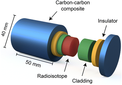 | ||
| Fig. 3 The schematic depicts the configuration of the radioisotope heat source (RHS) which houses the radioisotope (red) at its core. The radioisotope is encased by cladding (green) to shield the outer parts from contamination and irradiation. Additional insulators (yellow) and carbon composite layers (blue) are strategically placed to protect the radioisotope from excessive temperatures and unforeseen accidents, respectively. This figure is redrawn by the authors based on the original figure.8 | ||
One RTG heat source design encases the radioisotopes fuel within a rectangular-shaped RHS, measuring 9.72 × 9.72 × 5.31 cm3.16 In this design, TEGs are mounted on the smaller surfaces of the RHS, while the larger surfaces are connected to additional RHS units. Alternatively, a six-sided polygon RHS design, as illustrated in Fig. 4,8 keeps the major areas of the fuel element insulated, providing one surface as the interface to connect with TEGs. This innovative polygon design minimizes the volume occupied by the radioisotope, which reduces the total weight of the RTGs for use in space exploration vehicles.
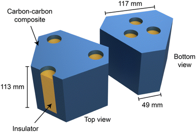 | ||
| Fig. 4 The schematic diagram of the six-sided polygon-shaped RHS is depicted, where the yellow and blue areas indicate the insulating container for the radioisotope and the carbon composite material, respectively. This figure is redrawn by the authors based on the original figure.8 | ||
2.2. Thermoelectric generator (TEG)
TEGs are mounted on the surface of the RHS, as illustrated in Fig. 2a, with numerous TE unicouples, as shown in Fig. 2b, connected in series to convert heat from the RHS into electricity. Historically, RTGs for space missions have utilized tellurium-based TE materials, notably PbTe, capable of operating within the temperature range of 300–800 K. These telluride-based TE materials have been integral to various generations of RTGs, including SNAP-3B, SNAP-9A, SNAP-19, SNAP-27, and Transit-RTG,10 which have been widely employed in space missions to generate electricity for satellites. Notably, two SNAP-19 RTGs were used to generate 56.4 W for the Nimbus III satellite, and SNAP-27 produced 70 W during the Apollo moon missions.18 However, the high operating temperature of PbTe necessitates the use of inert atmosphere gases, specifically argon or helium, to prevent the sublimation of TE materials. This phenomenon, typically occurring at the hot side of the TE leg, can lead to the deposition of sublimated elements on both the TE materials and electrodes, thereby reducing the TEG's efficiency.Over time, traditional tellurium-based alloys have been supplanted by SiGe-based alloys due to their superior efficiency and higher operating temperature of 1300 K. SiGe systems exhibit enhanced thermal performance, reducing the need for extensive heat dissipation measures, which allows the use of smaller cooling fins. Additionally, the transition to multi-layered insulation from bulk insulators has effectively reduced the overall mass of RTGs. SiGe-based TEGs can also operate efficiently without the need for inert gas, enabling the removal of certain components and further reducing their total weight.1,10 Hundreds of SiGe legs, combined with RHS modules, constitute the multi-hundred-watt radioisotope thermoelectric generators (MHW-RTG), which maintains a high power output of 150 W, diminishing to 125 W after five years of operation, with a specific power of approximately 4 W kg−1. These generators have been successfully deployed in various space missions, including Voyager, where they have provided years of uninterrupted electrical power for deep solar system exploration.10 Furthermore, advancements in SiGe-based RTGs have led to an increase in the number of TE legs from 312 to 572, paired with 18 RHSs, in the general-purpose heat source radioisotope thermoelectric generators (GPHS-RTG). This configuration achieves a higher power output of 300 W with a specific power of 5.1 W kg−1.10
The multi-mission radioisotope power generator (MMRTG), illustrated in Fig. 5, represents the next generation of space RTGs.19,20Fig. 6 showcases the employment of PbTe as the n-type and (GeTe)100−x(AgSbTe2)x (TAGS)/PbSnTe as the p-type segmented TE materials in the MMRTG.3 This innovative design enables its application across various environments, from the vacuum of space to planetary atmospheres. The MMRTG, equipped with 8 RHSs, can generate approximately 2 kW through 16 TE modules, each consisting of 48 TE unicouples. To prevent heat loss and oxidation of the TE materials, the TEG system is encased in argon gas and isolated from the RHS chamber to mitigate heat loss to the helium gas produced from fuel irradiation.21 The expected nominal power output of MMRTG in deep space missions is 125 W at the beginning of the mission and 110 W for ground missions.21 This power is sustained within the temperature range of 423 K to 823 K, exhibiting a specific power of 2.8 W kg−1.10 While the specific power of the MMRTG is lower than that of the SiGe-based RTGs previously discussed, it is important to note that SiGe is limited to vacuum environments, rendering them unsuited for surface missions on planets. In contrast, MMRTG's versatility allows it to generate electrical power for rovers or drones even on surface missions.
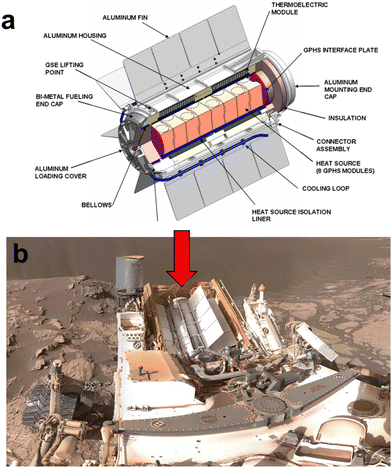 | ||
| Fig. 5 (a) Configuration of the multi-mission radioisotope thermoelectric generator (MMRTG); (b) MMRTG deployed on the curiosity rover during its Mars mission. These figures were redrawn by the authors based on the original figures21 (Image credit: NASA/JPL/Caltech). | ||
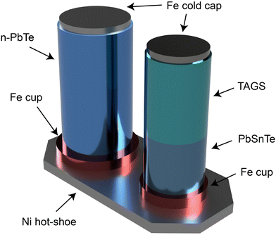 | ||
| Fig. 6 Illustration of thermoelectric (TE) unicouple used in the multi-mission radioisotope thermoelectric generator (MMRTG), featuring n-type PbTe and a segmented p-type leg design. In the segmented p-type leg, PbSbTe is positioned near the hot side, while (GeTe)100−x(AgSbTe2)x, known as TAGS, is placed closer to the cold side. This rendering was created by the authors based on the original figure3 (Image credit: NASA/JPL/Caltech). | ||
Following the success of MMRTG, its design has been recognized as reliable and highly efficient for future missions. However, given the concerns over the scarcity of 238Pu, the development of a next-generation MMRTG, termed the new enhanced MMRTG (eMMRTG), is critical.7 In eMMRTG's design, traditional TE materials are replaced with skutterudites, which are known for their exceptional TE properties and mechanical strength.19 Unlike TAGS, whose performance deteriorates above 800 K over time due to the degradation of segmentation in p-type leg, skutterudites demonstrate high-temperature stability, allowing a hot-side operation temperature between 800 and 850 K. This higher operating temperature increases the efficiency of both n- and p-type skutterudites, thereby improving the overall efficiency of eMMRTG.7
Recent advancements by the ESA have led to the development of Bi2Te3-based TE modules, specifically designed for deep-space probes using 241Am as the fuel source. These modules operate at lower hot side temperatures than those powered by 238Pu,8,9,22 enabling the use of Bi2Te3-based alloys as TE materials. Traditionally, Bi2Te3 alloys have seen limited use in RTGs due to their low operating temperature range of 300–600 K. However, their integration with 241Am heat sources is highly promising. This is attributed to 241Am emitting low-energy alpha and gamma radiation, which reduces the risk of introducing defects in electronic structures through irradiation. Mesalam et al. have demonstrated, through 10![[thin space (1/6-em)]](https://www.rsc.org/images/entities/char_2009.gif) 000 hours of vacuum testing, that RTG systems incorporating these Bi2Te3-based modules are relatively unaffected by changes over time.22,23 The test results indicate an annual efficiency degradation of less than 1% for these TE converters, capable of delivering a 10 W electrical power output. Future development efforts are focused on achieving a 50 W power output using the same design principles. The detailed information of the RTGs used in space missions is summarized in Table 2.
000 hours of vacuum testing, that RTG systems incorporating these Bi2Te3-based modules are relatively unaffected by changes over time.22,23 The test results indicate an annual efficiency degradation of less than 1% for these TE converters, capable of delivering a 10 W electrical power output. Future development efforts are focused on achieving a 50 W power output using the same design principles. The detailed information of the RTGs used in space missions is summarized in Table 2.
| RTGs | Radioisotope | TE materials | Operating temperature | Power output (W) | Scenarios | Ref. | |
|---|---|---|---|---|---|---|---|
| Systems for nuclear auxiliary power (SNAP) | 238Pu | Telluride-based | 300–800 K | 28–140 | Nimbus B-1 | 24 | |
| 90Sr | Viking 1&2 | ||||||
| 242Cm | Pioneer 10&11 (Jupiter mission) | ||||||
| 210Po | Apollo Lunar missions | ||||||
| Example | SNAP-3B | ||||||
| SNAP-19 | |||||||
| SNAP-27 | |||||||
| Transit-RTG | |||||||
| Multi-hundred-watt radioisotope thermoelectric generators (MHW-RTG) | 238Pu | SiGe-based | Up to 1300 K | 125–158 | Voyager 1&2 | ||
| General-purpose heat source radioisotope thermoelectric generators (GPHS-RTG) | 300 | Galileo | |||||
| Cassini | |||||||
| Ulysses | |||||||
| New Horizons | |||||||
| Multi-mission radioisotope thermoelectric generator (MMRTG) | GeTe-based, PbTe-based | 400–800 K | 110–125 | Mars rover | 21 | ||
| Enhanced multi-mission radioisotope thermoelectric generator (eMMRTG) | Skutterudites | Above 800 K | 25% higher than MMRTG (130–155) | Future mission | 19 | ||
| RTG from the European Space Agency (ESA) | 241Am | Bi–Te – based | 300–600 K | 10 | Under development | 25 | |
3. Thermoelectric materials for RTG
The energy conversion efficiency (ε) of RTGs typically falls within the range of 10%1 and is determined by the following equation: | (1) |
 | (2) |
In this equation, S, σ and κ are the Seebeck coefficient (V K−1), electrical conductivity (S m−1) and total thermal conductivity (W mK−1), respectively.26 The total thermal conductivity (κ) includes contributions from both the lattice (κph) and electronic (κe) thermal conductivities.27
Thermoelectric generators (TEGs) consist of pairs of n and p-type materials, characterized by negative and positive Seebeck coefficients, respectively. These pairs are usually chosen from materials with similar mechanical properties, particularly thermal expansion coefficients, to mitigate high-pressure stresses and potential damage to the TEGs at elevated temperatures.28 Disparities in the thermal expansion coefficients of n and p-type materials can cause significant stress and damage to TEGs. It is also important to note that the same material can exhibit either n or p-type by varying the doping levels of electrons or holes. For instance, B-doped SiGe and Na-doped PbTe are classified as p-type,29–31 while P-doped SiGe and I-doped PbTe are identified as n-type.32
In the preceding section, we introduced several TE materials suitable for RTG applications, including PbTe, SiGe, TAGS, Bi2Te3, and skutterudites. It is crucial to understand that each TE material exhibits its highest zT values at specific temperature ranges. For example, PbTe-based alloys reach their peak zT values between 600 and 900 K,33 whereas SiGe and Bi2Te3 achieve their maximum zT above 1200 K34 and within the 300 to 500 K range,35 respectively. Therefore, aligning the thermal output of the RHS with the optimal operating temperatures of the chosen TE materials is essential for maximizing RTG efficiency. Fig. 7 illustrates the correlation between the zT value and the optimal operating temperature for various p and n-type TE materials. Moreover, operating within the optimal temperature range can reduce thermal stress generated from thermal expansion, thereby enhancing the reliability of the RTG for long-duration missions without the need for maintenance. The temperature of the RHS is controlled through several methods. Firstly, the appropriate amount of radioisotope is selected based on the specific mission requirements. Additionally, insulating and conducting materials are utilized to minimize heat loss from the RHS and to direct heat flow to the surface area of the TE materials, respectively. Adjusting these materials around the RHS can affect the amount of heat dissipated into the surroundings. Furthermore, cooling tubes and radiator fins are employed to control the temperature by removing excess heat into space.25
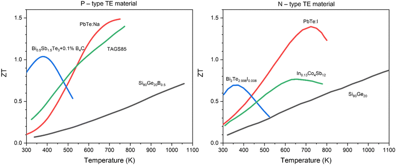 | ||
| Fig. 7 Relationships between zT and optimal operating temperature ranges for selected TE materials. On the left-hand side, p-type materials include B-doped SiGe,31 PbTe:Na,30 Bi0.5Sn1.5Te3 + 0.1B4C,36 and TAGS85.37 On the right-hand side, n-type materials feature SiGe,38 PbTe:I,32 Bi2Te2.992I0.008,35 In-filled CoSb3.39,40 | ||
To achieve high zT values, it is crucial to optimize the power factor (PF), represented by the S2σ term in eqn (2), while also minimizing thermal conductivity. As a result, the most promising TE materials are those characterized as “phonon-glass electron-crystal,” which are typically semiconductors.2 However, there is a trade-off among S, σ and κe, all of which are related to carrier concentration, making it challenging to optimize any single parameter without affecting the others.2,27,41 On the other hand, κph is the only parameter independent of carrier concentration. Therefore, the conventional approach to enhance the efficiency of TE materials involves optimizing the PF while simultaneously reducing κph. Specifically, the addition and/or substitution of certain atoms into TE materials can manipulate the electronic band structure and reduce κph through increased phonon-impurity scattering. Additionally, nanostructuring presents a promising strategy to achieving high zT values by scattering medium and long-wavelength phonons, without affecting electron scattering.42
3.1. Lead telluride alloys
Lead telluride (PbTe) features a simple, symmetrical cubic crystal structure resembling that of NaCl, with a space group of Fm![[3 with combining macron]](https://www.rsc.org/images/entities/char_0033_0304.gif) m, as illustrated in Fig. 8. It is widely employed as a conventional TE material in the temperature range of 600–800 K.43,44 Initially, PbTe was utilized in RTGs for space missions, achieving a zT of approximately 0.7 to 0.8. Advanced measurement technologies later revealed a zT of 1.4 for PbTe.44 Despite a temporary shift to SiGe due to its need for cover gas to prevent oxidization, PbTe and its alloy PbSnTe45–47 were eventually reintegrated into the MMRTG, as shown in Fig. 6.
m, as illustrated in Fig. 8. It is widely employed as a conventional TE material in the temperature range of 600–800 K.43,44 Initially, PbTe was utilized in RTGs for space missions, achieving a zT of approximately 0.7 to 0.8. Advanced measurement technologies later revealed a zT of 1.4 for PbTe.44 Despite a temporary shift to SiGe due to its need for cover gas to prevent oxidization, PbTe and its alloy PbSnTe45–47 were eventually reintegrated into the MMRTG, as shown in Fig. 6.
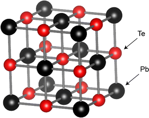 | ||
| Fig. 8 Schematic of the rock-salt structure of PbTe, with black and red spheres representing Pb and Te atoms, respectively. The crystal structure information was retrieved from the Materials Project database and visualized using the VESTA software.48 | ||
In recent decades, significant efforts have been made to improve the TE properties of PbTe alloys, resulting in remarkably high zT values. These enhancement strategies fall into three broad categories:
(1) Manipulating the electronic band structure, including band convergence,49–52 resonant states53,54 band alignment,55 flattened bands,56 and deep impurity levels,57 to achieve high PF.
(2) Optimizing carrier density by doping with I and Br at the Te site, or with Sb, Bi, Al, Ga, and In at the Pb site for n-type PbTe.58–60 Na and P are used for doping p-type PbTe.30,61 Noteworthy achievement include La-doped PbTe + Ag2Te with a zT of 1.6 at 775 K,62 Tl0.02Pb0.998Te with a zT of 1.5 at 775 K,54 Pb0.999TeIn0.001 with a zT of 0.85 at 623 K,63 Pb0.998Ga0.02Te with a zT of 1.4 at 775 K,57 Pb0.98Ga0.02Te0.96Se0.04 with a zT of 1.6 at 775 K,64 and PbTe-SrTe with a remarkable zT of 2.2 at 913 K.51
(3) Reducing lattice thermal conductivity by enhancing the phonon scattering from dislocations and point defects within the lattice.60,65,66 In addition, incorporating heavy elements in Pb contributes to phonon scattering through the Umklapp process,67 resulting in a lower κph.52,68,69 An example of this approach is the use of strain engineering by Wu et al. to reduce κph of Na0.03Eu0.03Sn0.02Pb0.92Te through in-grain dislocation, achieving a high zT of 2.6 at 773 K.70
3.2. SiGe alloys
Silicon Germanium (SiGe) alloys have been successfully utilized as TE materials in various missions, particularly for deep space exploration, due to their ability to operate in vacuum conditions without the need for cover gas. Notably, NASA used SiGe with zT values of 0.9 (n-type) and 0.5 (p-type) in RTGs in 1976.71 As a Si-based alloy, SiGe exhibits a diamond crystal structure and demonstrates excellent electrical properties at temperatures above 1200 K in vacuum, attributed to its intermetallic nature. Although pure Si single crystals display high thermal conductivity, resulting in a relatively low zT of 0.02–0.2 at temperatures from 300 to 1200 K,72 the substitution of Ge atoms into the Si lattice significantly enhances phonon scattering. This increase in phonon scattering reduces the lattice thermal conductivity to less than 10 W mK−1, allowing SiGe to achieve a maximum zT more than three times higher than that of Si.Nanostructuring techniques, such as ball milling29,73,74 or melt spinning31,75,76 followed by hot pressing or spark plasma sintering (SPS), have been employed to enhance the zT value of SiGe by reducing the grain size from single crystals to micro- and nano-grain polycrystals. These finer grains increase grain boundary scattering without negatively affecting electrical properties, thereby improving the zT values of SiGe to above 1.77 The zT of nanostructured n-type SiGe can be further enhanced to reach approximately 1.3–1.5 at 1173 K, double that of pristine SiGe,34,73 through carrier concentration optimizations by doping elements such as P and Sb.34,74,78,79 For p-type SiGe, B and Ga were doped to optimize electron acceptors, yielding zT values between 0.5 and 1.2 at 1073 K.29,31,79–81 In addition, nanocomposites have proven effective in reducing lattice thermal conductivity by scattering phonons. For example, integrating Si80Ge20P2 with nano-scale silicon carbide (SiC) at 0.23 vol% significantly reduces its thermal conductivity from 2.5 to 1.9 W mK−1, leading to an improved zT of 1.7 at 1173 K.38 Furthermore, the incorporation of second-phase nanoinclusions of silicide (XSi2, where X is a metallic transition element), such as VSi2,82 CrSi2,83 MoSi2,84 and WSi2,85,86 has been employed to reduce lattice thermal conductivity.87–89 A notable example is the addition of YSi2 to p-type SiGe, achieving a zT of 1.81 at 1100 K.90 However, the stoichiometry of the composites must be carefully considered during zT optimization to avoid unintended changes in carrier concentrations that could lead to PF degradation and limit zT enhancement.
3.3. GeTe and TAGS
Germanium Telluride (GeTe) is characterized as a narrow-band gap compound with a band gap of 0.3 eV, featuring a cubic crystal structure at high temperatures and transitioning to a rhombohedral structure at lower temperatures.91,92 It demonstrates excellent TE properties in its cubic phase and serves as a p-type TE material because of the significant amount of Ge vacancies. Consequently, strategies to enhance the zT of GeTe focus on manipulating the hole carrier concentration and reducing thermal conductivity.93 For example, by substituting Sb and In atoms at the Ge site, Hong et al. reduced the thermal conductivity from 7 to 1 W mK−1 at 300 K and achieved a zT of 2.3 at approximately 600 K.94 Li et al. successfully reduced the thermal conductivity to 0.7 and achieved a zT of 2.4 at 600 K by substituting Pb and Bi atoms at the Ge site.95 Tsai et al. suppressed the thermal conductivity of GeTe by alloying with Sb2Te3, inducing the coexistence of cubic and rhombohedral GeTe phases. This resulted in a zT of 2.5–2.9 at 720 K for (GeTe)0.95(Sb2Te3)0.05.96 Moreover, Bu et al. coalloyed GeTe with Cu2Te and PbSe to simultaneously optimize the carrier concentration, suppress the lattice thermal conductivity, and maintain a relatively high carrier mobility in p-type (Ge0.98Cu0.04Te)1−y(PbSe)y alloys. This approach resulted in a maximum zT value of over 2.5 at 800 K and an average zT of 1.8 between 300 and 800 K.97 The solid solution of GeTe and AgSbTe2, known as TAGS, is well-recognized for its high zT in the mid-temperature range (600 to 800 K) and for its mechanical stability at operating temperatures.98 Efforts dedicated to enhancing the zT of TAGS include doping with rare earth elements,99,100 optimizing the stoichiometry of GeTe–AgSbTe2 and vacancies,37,101 substituting variants elements,102–104 and microstructure engineering.105,106 Notably, Rodenkirchen et al. reported a high zT of 1.8 at 750 K and an average zT of 1.37 in the range of 300 to 800 K for TAGS.105As illustrated in Fig. 6, TAGS is employed in MMRTG, along with PbSnTe, as the p-type TE materials in the segmented design. The performance of the segmented TE leg increases when the two TE materials are compatible, and compatibility factor (ṡ), is determined using the equation:
 | (3) |
It is crucial that the compatibility factor do not differ by a factor greater than two,12,14,107 as this discrepancy can significantly reduce the overall efficiency of TEGs.14 As illustrated in Fig. 9, TAGS-8537 and PbSnTe47 exhibit excellent compatibility with each other between 300 to 600 K, which led to their selection as the p-type segmented legs for the MMRTG. However, compatibility is just one of several factors to be considered in selecting TE materials for TEGs that utilize segmented designs. Potential incompatibility may emerge from the degradation of segmented TE materials over the course of the mission, especially due to irradiation effects.108 Therefore, it is essential to consider other properties of the TE materials, such as thermal expansion coefficient, interdiffusion rates, mechanical properties, and resistance to irradiation, to ensure the durability of the RTGs.
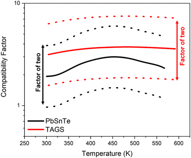 | ||
| Fig. 9 The compatibility factors of TAGS37 and PbSnTe47 in the p-type legs of the multi-mission radioisotope thermoelectric generator (MMRTG). The bold and dotted lines represent the compatibility factors calculated based on eqn (3) and the compatible range of a factor of two, respectively. | ||
3.4. Bi2Te3-based alloys
Bi2Te3 crystallizes in a rhombohedral structure, featuring quintuple-layers of Te1–Bi–Te2–Bi–Te1 separated by van der Waals bonding along the c-axis, as indicated in Fig. 10.109 The Te2–Bi bonds are longer, indicative of ionic bonding, while the Te1–Bi bonds are shorter, suggesting covalent bonding. The anisotropy in the microstructure and the relatively weak van der Waals bonding along the c-axis contribute to distinct TE properties between the a,b axis and c-axis. At room temperature, the bandgap of Bi2Te3 is measured at 0.13 eV.110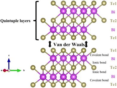 | ||
| Fig. 10 Bi2Te3 exhibits a rhombohedral structure consisting of quintuple layers, Te1–Bi–Te2–Bi–Te1, connected by van der Waals bonding along the c-axis. Information on the crystal structure was sourced from materialproject.org and visually represented using VESTA.48 | ||
Current strategies to enhance the TE properties of Bi2Te3 include nanostructuring and alloying. For instance, nanostructuring Bi2Te3 with SnTe through ball milling and hot pressing reduced its thermal conductivity from 1.4 to 0.9 W mK−1 at 373 K, achieving a zT value of 1.4.111 Additionally, synthesizing multiscale microstructures through melt-spinning and SPS in (Bi,Sb)2Te3 can also significantly lower thermal conductivity while preserving electrical properties, resulting in a zT of 1.5 at 390 K.112 Xu et al. utilized SPS to prepare highly porous Bi2Te2.5Se0.5 nanocomposites from hollow nanorods, achieving an ultralow lattice thermal conductivity of 0.13 W mK−1 and a zT of over 1 between 388 and 513 K.113 Another approach involves the use of excess Te in the melting process, which is released during sintering to create dense dislocation arrays at low-energy grain boundaries, scattering mid-wavelength phonons and yielding a zT of 1.81 at 350 K.114 The introduction of SiC nanoprecipitates into Bi2Te3 has also been explored to enhance its electrical conductivity and the Seebeck coefficient through increasing carrier concentration. SiC nanoprecipitates effectively scatter low-energy electrons without adversely affecting electrical conductivity, a phenomenon termed 'energy filtering'. Despite a slight increase in thermal conductivity due to enhanced electron heat transport, a high zT of 1.33 at 373 K has been reported, underscoring the success of this approach115,116 Notably, the addition of SiC not only improves the TE properties of Bi2Te3 but also enhances its hardness. Finally, various doping strategies aimed to enhance the TE properties of Bi2Te3, such as Cu-doped Bi2Te3 (zT = 0.67 at 415 K),117 Ce0.2Bi1.8Te3 (zT = 1.29 at 398 K),118 and Bi2−xGexTe3 (zT = 0.95 at 300 K)119 have been extensively reviewed by Saberi and Sajjadi, respectively.120
Bi2Te3, recognized for its outstanding TE properties, was originally employed as a cooling TE material, capable of generating a temperature difference of 40 K at room temperature.121 However, its application in RTGs for space missions has been limited due to its incompatibility with the operating temperature of 238Pu RHS and a low melting point at 858 K.110 Following the shift by the ESA to replace 238Pu with 241Am, Bi2Te3 was later adopted for their space missions.8 Given that 241Am emits alpha particles and slight gamma-rays, evaluating the irradiation resistance of Bi2Te3 TEGs is crucial to ensure their structural integrity during missions. A report by Mesalam et al. revealed the ratio between post- and pre-irradiation zT values ranges from 0.7 to 1.2. Various trends in zT after irradiation in the literature are attributed to the effect of irradiation on the TE material's atomic structure, leading to the formation of vacancies and interstitials, thereby impacting carrier concentration, σ and S values.22,122
3.5. Skutterudites (CoSb3)
Skutterudite, a CoSb3-based alloy, crystallizes into a cubic crystal structure characterized by octahedrons within the Im![[3 with combining macron]](https://www.rsc.org/images/entities/char_0033_0304.gif) space group, as illustrated in Fig. 11. This structure features a void at the center of the lattice that can accommodate specific atoms, enhancing phonon scattering and thereby improving electrical properties. As a narrow bandgap semiconductor (0.22 eV), CoSb3 exhibits high carrier concentration and excellent electrical conductivity. Additionally, it possesses a high Seebeck coefficient due to its flat energy band.39 The presence of a covalent bond between Co and Sb, coupled with a high void density in the structure, leads to a high thermal conductivity of approximately 10 W mK−1 for a single crystal,123 resulting in a low zT.39 To enhance the thermal conductivity of skutterudites, one effective strategy involves the substitution of atoms at the Co or Sb sites. For instance, doping Te on the Sb site not only reduces thermal conductivity but also acts as an electron donor to improve electrical properties, achieving a zT of 0.93 at 800 K.124 Similarly, Ni doping at the Co site effectively reduces thermal conductivity from 11 to 6 W mK−1 at room temperature.125 Binary substitution at both the Co and Sb sites, as in the case of Co1−xNix(Sb1−yTey)3, yields a zT of 0.65 at 800 K.126 Furthermore, co-doping of Ge and Te at the Sb site, aimed at increasing Te solubility and enhancing point defect scattering, has resulted in a high zT of 1.1 at 800 K.127 Another notable approach intended to reduce thermal conductivity involves the introduction of filling atoms into the voids in the microstructure. For instance, Zhang et al. incorporated Li as filling atom to effective scatter phonons. The optimized composition of Li-filled CoSb3, Li0.36Co4Sb12, demonstrated a high and stable PF value of 6 mW mK−2 from room temperature to 700 K, along with an excellent zT of 1.3 at 700 K.128
space group, as illustrated in Fig. 11. This structure features a void at the center of the lattice that can accommodate specific atoms, enhancing phonon scattering and thereby improving electrical properties. As a narrow bandgap semiconductor (0.22 eV), CoSb3 exhibits high carrier concentration and excellent electrical conductivity. Additionally, it possesses a high Seebeck coefficient due to its flat energy band.39 The presence of a covalent bond between Co and Sb, coupled with a high void density in the structure, leads to a high thermal conductivity of approximately 10 W mK−1 for a single crystal,123 resulting in a low zT.39 To enhance the thermal conductivity of skutterudites, one effective strategy involves the substitution of atoms at the Co or Sb sites. For instance, doping Te on the Sb site not only reduces thermal conductivity but also acts as an electron donor to improve electrical properties, achieving a zT of 0.93 at 800 K.124 Similarly, Ni doping at the Co site effectively reduces thermal conductivity from 11 to 6 W mK−1 at room temperature.125 Binary substitution at both the Co and Sb sites, as in the case of Co1−xNix(Sb1−yTey)3, yields a zT of 0.65 at 800 K.126 Furthermore, co-doping of Ge and Te at the Sb site, aimed at increasing Te solubility and enhancing point defect scattering, has resulted in a high zT of 1.1 at 800 K.127 Another notable approach intended to reduce thermal conductivity involves the introduction of filling atoms into the voids in the microstructure. For instance, Zhang et al. incorporated Li as filling atom to effective scatter phonons. The optimized composition of Li-filled CoSb3, Li0.36Co4Sb12, demonstrated a high and stable PF value of 6 mW mK−2 from room temperature to 700 K, along with an excellent zT of 1.3 at 700 K.128
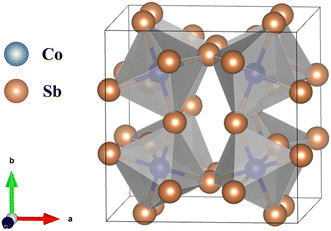 | ||
Fig. 11 Illustration of the crystal structure of the CoSb3-based alloy, which crystallizes into octahedrons within the space group Im![[3 with combining macron]](https://www.rsc.org/images/entities/char_0033_0304.gif) . The structure is characterized by a void at the center of the cubic lattice. Crystal structure information was sourced from materialproject.org and visually represented using VESTA.48 . The structure is characterized by a void at the center of the cubic lattice. Crystal structure information was sourced from materialproject.org and visually represented using VESTA.48 | ||
However, relying solely on single-element filling or substitution proves inadequate for maximizing the TE properties of CoSb3. Sales et al. introduced the concept of using multiple filler atoms, La and Ce, in combination with Fe substitution at the Co-site. This strategy significantly reduced the thermal conductivity from 10 to 1.6 W mK−1 at room temperature and achieved a zT of 0.9 at 800 K.129 A co-doping approach using Dy and Ni, optimized to Dy0.4Co3.2Ni0.8Sb12, exhibited a high zT of 1.4 at 773 K, with the Ni doping also enhancing the mechanical properties.130 Furthermore, Shi et al. achieved a high zT of 1.7 at 850 K using multiple filler atoms, such as Ba, La, and Yb, in CoSb3.131 Nanostructuring of CoSb3 has also been explored to enhance its TE properties, where specific nano grain sizes scatter phonons at the grain boundaries. For instance, Rogl et al. synthesized the triple-filled skutterudite (Sr0.33Ba0.33Yb0.33)0.35Co4Sb12.3 using ball milling and hot-pressing techniques, achieving a PF of 6 mW mK−2 and a zT of 1.4 at 823 K. Subsequently, the (Sr0.25Ba0.25Yb0.5)0.5Co4Sb12.5 sample, incorporating homogeneous nanosized Yb2O3 impurities, exhibited a zT of 1.6 at 835 K. High-pressure torsion was applied to further reduce its thermal conductivity, resulting in an enhanced zT of 1.9 at 835 K.132 Additionally, melt-spinning followed by SPS was utilized to prepare nanostructured (In, Ce)CoSb3 nanocomposites, incorporating a wide range of nanoparticles to strongly scatter phonons and achieve a zT of 1.5 at 850 K.133
4. Practical usage
The optimization and design of TEGs and RHSs are critical in enhancing the electrical energy output of RTGs. Beyond TE properties, various factors must be considered prior to the selection and assembly of RTGs for practical use. These factors include the stability of TE materials at operating temperatures and their resistance to irradiation, both of which are essential for mitigating RTG degradation during missions. A significant issue concerning stability is the sublimation of chalcogen elements, such as Te and Se, which are primary components in most TE materials. Sublimation can result in numerous problems, such as a reduction in the TE leg's cross-sectional area, an increase in electrical and thermal resistance, and possible impacts on the junction between TE materials and electrodes, potentially resulting in system failure. Although sublimation cannot be entirely prevented, it can be delayed through the use of cover gases and/or coatings on TE legs.1 Additionally, the high operating temperature may facilitate interdiffusion between the TE material and the electrode bonding material, potentially reducing TE performance.134,135 Consequently, a diffusion barrier should be installed between the TE legs and the electrodes to inhibit the formation of secondary phases.136 Moreover, the high operating temperature, large temperature differences between the hot and cold sides, and mismatch in thermal expansion coefficients between the p- and n-type TE legs can induce substantial internal stresses, risking long-term RTG failure. To enhance structural integrity, TE couples should be selected to minimize difference in thermal expansion coefficients, and optimization of the surface area and length of n- and p-type TE legs can help mitigate these stresses.137 Finally, while this review has primarily focused on large-scale RTGs used in space explorations, RTGs with smaller sizes and lower power outputs also hold promise for niche applications, such as powering remote sensors or implantable medical devices like pacemakers.138–140 However, significant efforts are required to advance the use of micro-RTGs, as challenges remain in the fabrication of small-scale TE modules on the order of centimeters and ensuring effective contact between the miniaturized heat sources and TE couples.141 Moreover, as micro-RTGs will operate at significantly lower power outputs and temperatures compared to their space exploration counterparts, developing TE materials with optimal zT values at low to intermediate temperatures remains critical.5. Conclusion
This review presents a comprehensive examination of the evolution of RTGs over the past fifty years, alongside prospects for future missions. It offers an in-depth analysis of the meticulous selection of RHSs and TE materials across different RTG generations. The discussion delves into the TE properties of conventional materials used in RTGs and explores promising techniques to enhance these properties. A key focus of this review is the enhancement of zT through two fundamental principles: increasing the PF by optimizing the electronic band structure and reducing κ by increasing phonon scattering. While the ongoing development of TE materials with high zT is crucial to advancements in RTG design, these materials must also meet other criteria essential for RTG integration, such as strength, safety, and weight considerations. Moreover, the authors emphasize the importance of prioritizing safety in RTG design for future space travels, aligning with humanity's broader aspirations. This perspective underscores the need for RTGs to incorporate enhanced safety measures to safeguard human well-being during space exploration in the foreseeable future.Conflicts of interest
There are no conflicts to declare.Acknowledgements
This work was supported in part by MEXT/JSPS KAKENHI, grant number 24K08029.References
- C. Candolfi, S. E. Oualid, D. Ibrahim, S. Misra, O. E. Hamouli, A. Léon, A. Dauscher, P. Masschelein, P. Gall, P. Gougeon, C. Semprimoschnig and B. Lenoir, CEAS Space J., 2021, 13, 325–340 CrossRef.
- G. J. Snyder and E. S. Toberer, Nat. Mater., 2008, 7, 105 CrossRef CAS PubMed.
- R. Cataldo and G. Bennett, U.S. Space Radioisotope Power Systems and Applications, Past, Present and Future, 2011 DOI:10.5772/23914.
- M. L. Terranova, Int. J. Energy Res., 2022, 46, 19368–19393 CrossRef.
- M. A. Zoui, S. Bentouba, J. G. Stocholm and M. Bourouis, Energies, 2020, 13, 3606 CrossRef CAS.
- G. Bennett, in 4th International Energy Conversion Engineering Conference and Exhibit (IECEC) DOI:10.2514/6.2006-4191.
- T. C. Holgate, R. Bennett, T. Hammel, T. Caillat, S. Keyser and B. Sievers, J. Electron. Mater., 2015, 44, 1814–1821 CrossRef CAS.
- R. M. Ambrosi, H. Williams, E. J. Watkinson, A. Barco, R. Mesalam, T. Crawford, C. Bicknell, P. Samara-Ratna, D. Vernon, N. Bannister, D. Ross, J. Sykes, M.-C. Perkinson, C. Burgess, C. Stroud, S. Gibson, A. Godfrey, R. G. Slater, M. J. Reece, K. Chen, K. Simpson, R. Tuley, M. Sarsfield, T. P. Tinsley, K. Stephenson, D. Freis, J.-F. Vigier, R. J. M. Konings, C. Fongarland, M. Libessart, J. Merrifield, D. P. Kramer, J. Byrne and B. Foxcroft, Space Sci. Rev., 2019, 215, 55 CrossRef CAS.
- H. R. Williams, R. M. Ambrosi, N. P. Bannister, P. Samara-Ratna and J. Sykes, Int. J. Energy Res., 2012, 36, 1192–1200 CrossRef CAS.
- J. Yang and T. Caillat, MRS Bull., 2006, 31, 224–229 CrossRef CAS.
- X. Hu, P. Jood, M. Ohta, M. Kunii, K. Nagase, H. Nishiate, M. G. Kanatzidis and A. Yamamoto, Energy Environ. Sci., 2016, 9, 517–529 RSC.
- C. Hadjistassou, E. Kyriakides and J. Georgiou, Energy Convers. Manage., 2013, 66, 165–172 CrossRef CAS.
- C. S. R. Matthes, D. F. Woerner, T. J. Hendricks, J. Fleurial, K. I. Oxnevad, C. D. Barklay and J. F. Zakrajsek, 2018, IEEE Aerospace Conference, Big Sky, MT, USA, 2018, pp. 1–9 DOI:10.1109/AERO.2018.8396738.
- G. J. Snyder, Appl. Phys. Lett., 2004, 84, 2436–2438 CrossRef CAS.
- N. Jaziri, A. Boughamoura, J. Müller, B. Mezghani, F. Tounsi and M. Ismail, Energy Rep., 2020, 6, 264–287 CrossRef.
- A. Sanchez-Torres, Radioisotope Power Systems for Space Applications, 2011 DOI:10.5772/20928.
- H. Inouye, C. T. Liu and R. G. Donnelly, New Platinum–Rhodium–Tungsten Alloys for Space Isotopic Heat Sources, Oak Ridge National Laboratory, United States, 1972 Search PubMed.
- J. R. Bates, W. W. Lauderdale and H. Kernaghan, ALSEP Termination Report, NASA, 1979 Search PubMed.
- D. Woerner, J. Electron. Mater., 2016, 45, 1278–1283 CrossRef CAS.
- C. Barklay, D. Kramer, C. Whiting, R. Ambrosi and R. Mesalam, 2020 IEEE Aerospace Conference, Big Sky, MT, USA, 2020, pp. 1–7 DOI:10.1109/AERO47225.2020.9172602.
- T. Hammel, R. Bennett, W. Otting and S. Fanale, in 7th International Energy Conversion Engineering Conference, 2009 DOI:10.2514/6.2009-4576.
- R. Mesalam, H. R. Williams, R. M. Ambrosi, D. P. Kramer, C. D. Barklay, J. García-Cañadas, K. Stephenson and D. P. Weston, AIP Adv., 2019, 9, 055006 CrossRef.
- R. Mesalam, H. R. Williams, R. M. Ambrosi, J. García-Cañadas and K. Stephenson, Appl. Energy, 2018, 226, 1208–1218 CrossRef.
- NASA, Powering Radioisotope Thermoelectric Generators (RTGs), https://science.nasa.gov/planetary-science/programs/radioisotope-power-systems/power-radioisotope-thermoelectric-generators/#hds-sidebar-nav-1).
- R. M. Ambrosi, H. Williams, E. J. Watkinson, A. Barco, R. Mesalam, T. Crawford, C. Bicknell, P. Samara-Ratna, D. Vernon, N. Bannister, D. Ross, J. Sykes, M.-C. Perkinson, C. Burgess, C. Stroud, S. Gibson, A. Godfrey, R. G. Slater, M. J. Reece, K. Chen, K. Simpson, R. Tuley, M. Sarsfield, T. P. Tinsley, K. Stephenson, D. Freis, J.-F. Vigier, R. J. M. Konings, C. Fongarland, M. Libessart, J. Merrifield, D. P. Kramer, J. Byrne and B. Foxcroft, Space Sci. Rev., 2019, 215, 55 CrossRef CAS.
- X.-L. Shi, J. Zou and Z.-G. Chen, Chem. Rev., 2020, 120, 7399–7515 CrossRef CAS PubMed.
- J. R. Sootsman, D. Y. Chung and M. G. Kanatzidis, Angew. Chem., Int. Ed., 2009, 48, 8616 CrossRef CAS PubMed.
- L. Pavlova, Y. Shtern and E. Kirilenko, J. Mater. Sci., 2017, 52, 921–934 CrossRef CAS.
- G. Joshi, H. Lee, Y. Lan, X. Wang, G. Zhu, D. Wang, R. W. Gould, D. C. Cuff, M. Y. Tang, M. S. Dresselhaus, G. Chen and Z. Ren, Nano Lett., 2008, 8, 4670–4674 CrossRef CAS PubMed.
- Y. Pei, A. LaLonde, S. Iwanaga and G. J. Snyder, Energy Environ. Sci., 2011, 4, 2085–2089 RSC.
- S. Wongprakarn, S. Pinitsoontorn, S.-A. Tanusilp and K. Kurosaki, Mater. Sci. Semicond. Process., 2018, 88, 239–249 CrossRef CAS.
- A. D. LaLonde, Y. Pei and G. J. Snyder, Energy Environ. Sci., 2011, 4, 2090–2096 RSC.
- T. Fu, X. Yue, H. Wu, C. Fu, T. Zhu, X. Liu, L. Hu, P. Ying, J. He and X. Zhao, J. Materiomics, 2016, 2, 141–149 CrossRef.
- X. W. Wang, H. Lee, Y. C. Lan, G. H. Zhu, G. Joshi, D. Z. Wang, J. Yang, A. J. Muto, M. Y. Tang, J. Klatsky, S. Song, S. M. Dresselhaus, G. Chen and Z. F. Gen, Appl. Phys. Lett., 2008, 93, 193121 CrossRef.
- I. T. Witting, T. C. Chasapis, F. Ricci, M. Peters, N. A. Heinz, G. Hautier and G. J. Snyder, Adv. Electron. Mater., 2019, 5, 1800904 CrossRef.
- H. R. Williams, R. M. Ambrosi, K. Chen, U. Friedman, H. Ning, M. J. Reece, M. C. Robbins, K. Simpson and K. Stephenson, J. Alloys Compd., 2015, 626, 368–374 CrossRef CAS.
- T. Schröder, T. Rosenthal, N. Giesbrecht, M. Nentwig, S. Maier, H. Wang, G. J. Snyder and O. Oeckler, Inorg. Chem., 2014, 53, 7722–7729 CrossRef PubMed.
- S. Bathula, M. Jayasimhadri, B. Gahtori, A. Kumar, A. K. Srivastava and A. Dhar, Phys. Chem. Chem. Phys., 2017, 19, 25180–25185 RSC.
- Z.-Y. Liu, J.-L. Zhu, X. Tong, S. Niu and W.-Y. Zhao, J. Adv. Ceram., 2020, 9, 647–673 CrossRef CAS.
- S. Le Tonquesse, É. Alleno, V. Demange, V. Dorcet, L. Joanny, C. Prestipino, O. Rouleau and M. Pasturel, J. Alloys Compd., 2019, 796, 176–184 CrossRef CAS.
- T. M. Tritt and M. A. Subramanian, MRS Bull., 2006, 31, 188 CrossRef.
- M. G. Kanatzidis, Chem. Mater., 2010, 22, 648–659 CrossRef CAS.
- Y. Xiao and L.-D. Zhao, npj Quantum Mater., 2018, 3, 55 CrossRef.
- A. D. LaLonde, Y. Pei, H. Wang and G. Jeffrey Snyder, Mater. Today, 2011, 14, 526–532 CrossRef CAS.
- A. D. Lalonde and P. D. Moran, J. Electron. Mater., 2010, 39, 8–14 CrossRef CAS.
- V. Jovovic, S. J. Thiagarajan, J. P. Heremans, T. Komissarova, D. Khokhlov and A. Nicorici, J. Appl. Phys., 2008, 103(5), 053710 CrossRef.
- A. D. Lalonde and P. D. Moran, J. Electron. Mater., 2010, 39, 8–14 CrossRef CAS.
- K. Momma and F. Izumi, J. Appl. Crystallogr., 2011, 44, 1272–1276 CrossRef CAS.
- Y. Pei, X. Shi, A. LaLonde, H. Wang, L. Chen and G. J. Snyder, Nature, 2011, 473, 66–69 CrossRef CAS PubMed.
- L. D. Zhao, H. J. Wu, S. Q. Hao, C. I. Wu, X. Y. Zhou, K. Biswas, J. Q. He, T. P. Hogan, C. Uher, C. Wolverton, V. P. Dravid and M. G. Kanatzidis, Energy Environ. Sci., 2013, 6, 3346–3355 RSC.
- K. Biswas, J. He, I. D. Blum, C.-I. Wu, T. P. Hogan, D. N. Seidman, V. P. Dravid and M. G. Kanatzidis, Nature, 2012, 489, 414–418 CrossRef CAS PubMed.
- G. Tan, F. Shi, S. Hao, L.-D. Zhao, H. Chi, X. Zhang, C. Uher, C. Wolverton, V. P. Dravid and M. G. Kanatzidis, Nat. Commun., 2016, 7, 12167 CrossRef CAS PubMed.
- J. P. Heremans, B. Wiendlocha and A. M. Chamoire, Energy Environ. Sci., 2012, 5, 5510–5530 RSC.
- J. P. Heremans, V. Jovovic, E. S. Toberer, A. Saramat, K. Kurosaki, A. Charoenphakdee, S. Yamanaka and G. J. Snyder, Science, 2008, 321, 554–557 CrossRef CAS PubMed.
- K. Biswas, J. He, Q. Zhang, G. Wang, C. Uher, V. P. Dravid and M. G. Kanatzidis, Nat. Chem., 2011, 3, 160–166 CrossRef CAS PubMed.
- Y. Xiao, H. Wu, J. Cui, D. Wang, L. Fu, Y. Zhang, Y. Chen, J. He, S. J. Pennycook and L.-D. Zhao, Energy Environ. Sci., 2018, 11, 2486–2495 RSC.
- X. Su, S. Hao, T. P. Bailey, S. Wang, I. Hadar, G. Tan, T.-B. Song, Q. Zhang, C. Uher, C. Wolverton, X. Tang and M. G. Kanatzidis, Adv. Energy Mater., 2018, 8, 1800659 CrossRef.
- L. Fu, M. Yin, D. Wu, W. Li, D. Feng, L. Huang and J. He, Energy Environ. Sci., 2017, 10, 2030–2040 RSC.
- J. Zhang, D. Wu, D. He, D. Feng, M. Yin, X. Qin and J. He, Adv. Mater., 2017, 29, 1703148 CrossRef PubMed.
- Q. Zhang, Q. Song, X. Wang, J. Sun, Q. Zhu, K. Dahal, X. Lin, F. Cao, J. Zhou, S. Chen, G. Chen, J. Mao and Z. Ren, Energy Environ. Sci., 2018, 11, 933–940 RSC.
- Q. Zhang, F. Cao, W. Liu, K. Lukas, B. Yu, S. Chen, C. Opeil, D. Broido, G. Chen and Z. Ren, J. Am. Chem. Soc., 2012, 134, 10031–10038 CrossRef CAS PubMed.
- Y. Pei, J. Lensch-Falk, E. S. Toberer, D. L. Medlin and G. J. Snyder, Adv. Funct. Mater., 2011, 21, 241–249 CrossRef CAS.
- T. Parashchuk, Z. Dashevsky and K. Wojciechowski, J. Appl. Phys., 2019, 125, 245103 CrossRef.
- Y. Shi, Y. Tang, K. Liu, S. Zhong, S. Chen, L. Yu, J. Wu, Q. Zhang, X. Su and X. Tang, Mater. Today Phys., 2022, 27, 100766 CrossRef CAS.
- J. He, S. N. Girard, M. G. Kanatzidis and V. P. Dravid, Adv. Funct. Mater., 2010, 20, 764–772 CrossRef CAS.
- R. Knura, T. Parashchuk, A. Yoshiasa and K. T. Wojciechowski, Dalton Trans., 2021, 50, 4323–4334 RSC.
- C. Chang and L.-D. Zhao, Mater. Today Phys., 2018, 4, 50–57 CrossRef.
- O. Delaire, J. Ma, K. Marty, A. F. May, M. A. McGuire, M. H. Du, D. J. Singh, A. Podlesnyak, G. Ehlers, M. D. Lumsden and B. C. Sales, Nat. Mater., 2011, 10, 614–619 CrossRef CAS PubMed.
- D. M. Rowe and C. M. Bhandari, Appl. Phys. Lett., 1985, 47, 255–257 CrossRef CAS.
- Y. Wu, Z. Chen, P. Nan, F. Xiong, S. Lin, X. Zhang, Y. Chen, L. Chen, B. Ge and Y. Pei, Joule, 2019, 3, 1276–1288 CrossRef CAS.
- B. Yu, M. Zebarjadi, H. Wang, K. Lukas, H. Wang, D. Wang, C. Opeil, M. S. Dresselhaus, G. Chen and Z. F. Ren, Nano Lett., 2012, 12, 2077 CrossRef CAS PubMed.
- S. K. Bux, R. G. Blair, P. K. Gogna, H. Lee, G. Chen, M. S. Dresselhaus, R. B. Kaner and J. Fleurial, Adv. Funct. Mater., 2009, 19, 2445 CrossRef CAS.
- S. Bathula, M. Jayasimhadri, N. Singh, A. K. Srivastava, J. Pulikkotil, A. Dhar and R. C. Budhani, Appl. Phys. Lett., 2012, 101, 213902 CrossRef.
- S. Bathula, M. Jayasimhadri, A. Dhar, M. Saravanan, D. K. Misra, N. Singh, A. K. Srivastava and R. C. Budhani, MRS Online Proceedings Library, 2012, vol. 1490, pp. 74–79.
- A. Vishwakarma, N. S. Chauhan, R. Bhardwaj, K. K. Johari, S. R. Dhakate, B. Gahtori and S. Bathula, J. Electron. Mater., 2021, 50, 364–374 CrossRef CAS.
- S. Wongprakarn, S. Pinitsoontorn, S.-A. Tanusilp and K. Kurosaki, Phys. Status Solidi A, 2017, 214, 1700235 CrossRef.
- G. H. Zhu, H. Lee, Y. C. Lan, X. W. Wang, G. Joshi, D. Z. Wang, J. Yang, D. Vashaee, H. Guilbert, A. Pillitteri, M. S. Dresselhaus, G. Chen and Z. F. Ren, Phys. Rev. Lett., 2009, 102, 196803 CrossRef CAS PubMed.
- C. Wang, S. Lin, H. Chen, Y. Zhao, L. Zhao, H. Wang, D. Huo and X. Chen, Energy Convers. Manage., 2015, 94, 331–336 CrossRef CAS.
- J. P. Fleurial, J. Vandersande, N. Scoville, C. Bajgar and J. Beaty, AIP Conf. Proc., 1993, 271, 759–764 CrossRef CAS.
- S. Bathula, M. Jayasimhadri, B. Gahtori, N. K. Singh, K. Tyagi, A. K. Srivastava and A. Dhar, Nanoscale, 2015, 7, 12474–12483 RSC.
- S. Lin, C. Wang, H. Chen, D. Huo, N. Savvides and X. Chen, Funct. Mater. Lett., 2014, 07, 1450008 CrossRef.
- S. Tanusilp, K. Kurosaki, A. Yusufu, Y. Ohishi, H. Muta and S. Yamanaka, J. Electron. Mater., 2017, 46, 3249 CrossRef CAS.
- Z. Zamanipour and D. Vashaee, J. Appl. Phys., 2012, 112, 093714 CrossRef.
- K. Favier, G. Bernard-Granger, C. Navone, M. Soulier, M. Boidot, J. Leforestier, J. Simon, J.-C. Tedenac and D. Ravot, Acta Mater., 2014, 64, 429–442 CrossRef CAS.
- J. Mackey, F. Dynys and A. Sehirlioglu, Acta Mater., 2015, 98, 263–274 CrossRef CAS.
- F. W. Dynys, A. Sayir, J. Mackey and A. Sehirlioglu, J. Alloys Compd., 2014, 604, 196–203 CrossRef CAS.
- N. Mingo, D. Hauser, P. N. Kobayashi, M. Plissonnier and A. Shakouri, Nano Lett., 2009, 9, 711 CrossRef CAS PubMed.
- K. Kurosaki, A. Yusufu, Y. Miyazaki, Y. Ohishi, H. Muta and S. Yamanaka, Mater. Trans., 2016, 57, 1018 CrossRef CAS.
- A. Nozariasbmarz, A. Agarwal, Z. A. Coutant, M. J. Hall, J. Liu, R. Liu, A. Malhortra and P. Norouzzadeh, Jpn. J. Appl. Phys., 2017, 56, 05DA04 CrossRef.
- S. Ahmad, A. Singh, A. Bohra, R. Basu, S. Bhattacharya, R. Bhatt, K. N. Meshram, M. Roy, S. K. Sarkar, Y. Hayakawa, A. K. Debnath, D. K. Aswal and S. K. Gupta, Nano Energy, 2016, 27, 282–297 CrossRef CAS.
- Y. Gelbstein, J. Davidow, E. Leshem, O. Pinshow and S. Moisa, Phys. Status Solidi B, 2014, 251, 1431–1437 CrossRef CAS.
- X. Zhang, Z. Bu, S. Lin, Z. Chen, W. Li and Y. Pei, Joule, 2020, 4, 986–1003 CrossRef CAS.
- E. M. Levin, M. F. Besser and R. Hanus, J. Appl. Phys., 2013, 114, 083713 CrossRef.
- M. Hong, Z.-G. Chen, L. Yang, Y.-C. Zou, M. S. Dargusch, H. Wang and J. Zou, Adv. Mater., 2018, 30, 1705942 CrossRef PubMed.
- J. Li, X. Zhang, Z. Chen, S. Lin, W. Li, J. Shen, I. T. Witting, A. Faghaninia, Y. Chen, A. Jain, L. Chen, G. J. Snyder and Y. Pei, Joule, 2018, 2, 976–987 CrossRef CAS.
- Y.-F. Tsai, P.-C. Wei, L. Chang, K.-K. Wang, C.-C. Yang, Y.-C. Lai, C.-R. Hsing, C.-M. Wei, J. He, G. J. Snyder and H.-J. Wu, Adv. Mater., 2021, 33, 2005612 CrossRef CAS PubMed.
- Z. Bu, X. Zhang, B. Shan, J. Tang, H. Liu, Z. Chen, S. Lin, W. Li and Y. Pei, Sci. Adv., 2021, 7, eabf2738 CrossRef CAS PubMed.
- A. Kumar, P. A. Vermeulen, B. J. Kooi, J. Rao, S. Schwarzmüller, O. Oeckler and G. R. Blake, RSC Adv., 2018, 8, 42322–42328 RSC.
- E. M. Levin, S. L. Bud'ko and K. Schmidt-Rohr, Adv. Funct. Mater., 2012, 22, 2766–2774 CrossRef CAS.
- E. M. Levin, B. A. Cook, J. L. Harringa, S. L. Bud’ko, R. Venkatasubramanian and K. Schmidt-Rohr, Adv. Funct. Mater., 2011, 21, 441–447 CrossRef CAS.
- H.-X. Liu, X.-Y. Zhang, Z.-L. Bu, W. Li and Y.-Z. Pei, Rare Met., 2022, 41, 921–930 CrossRef CAS.
- X. Shi, J. R. Salvador, J. Yang and H. Wang, Sci. Adv. Mater., 2011, 3, 667–671 CrossRef CAS.
- T. Schröder, S. Schwarzmüller, C. Stiewe, J. de Boor, M. Hölzel and O. Oeckler, Inorg. Chem., 2013, 52, 11288–11294 CrossRef PubMed.
- T. Schröder, T. Rosenthal, N. Giesbrecht, S. Maier, E.-W. Scheidt, W. Scherer, G. J. Snyder, W. Schnick and O. Oeckler, J. Mater. Chem. A, 2014, 2, 6384–6395 RSC.
- C. Rodenkirchen, M. Cagnoni, S. Jakobs, Y. Cheng, J. Keutgen, Y. Yu, M. Wuttig and O. Cojocaru-Mirédin, Adv. Funct. Mater., 2020, 30, 1910039 CrossRef CAS.
- T. Zhu, H. Gao, Y. Chen and X. Zhao, J. Mater. Chem. A, 2014, 2, 3251–3256 RSC.
- G. J. Snyder and T. S. Ursell, Phys. Rev. Lett., 2003, 91, 148301 CrossRef PubMed.
- A. M. Abd El-Hameed, NRIAG J. Astron. Geophys., 2022, 11, 313–324 CrossRef.
- B. Cai, H. Hu, H.-L. Zhuang and J.-F. Li, J. Alloys Compd., 2019, 806, 471–486 CrossRef CAS.
- C. Gayner and K. K. Kar, Prog. Mater. Sci., 2016, 83, 330–382 CrossRef CAS.
- B. Poudel, Q. Hao, Y. Ma, Y. Lan, A. Minnich, B. Yu, X. Yan, D. Wang, A. Muto, D. Vashaee, X. Chen, J. Liu, M. S. Dresselhaus, G. Chen and Z. Ren, Science, 2008, 320, 634–638 CrossRef CAS PubMed.
- W. Xie, J. He, H. J. Kang, X. Tang, S. Zhu, M. Laver, S. Wang, J. R. D. Copley, C. M. Brown, Q. Zhang and T. M. Tritt, Nano Lett., 2010, 10, 3283–3289 CrossRef CAS PubMed.
- B. Xu, T. Feng, M. T. Agne, L. Zhou, X. Ruan, G. J. Snyder and Y. Wu, Angew. Chem., Int. Ed., 2017, 56, 3546–3551 CrossRef CAS PubMed.
- S. I. Kim, K. H. Lee, H. A. Mun, H. S. Kim, S. W. Hwang, J. W. Roh, D. J. Yang, W. H. Shin, X. S. Li, Y. H. Lee, G. J. Snyder and S. W. Kim, Science, 2015, 348, 109–114 CrossRef CAS PubMed.
- J. Li, Q. Tan, J.-F. Li, D.-W. Liu, F. Li, Z.-Y. Li, M. Zou and K. Wang, Adv. Funct. Mater., 2013, 23, 4317–4323 CrossRef CAS.
- D.-W. Liu, J.-F. Li, C. Chen and B.-P. Zhang, J. Electron. Mater., 2011, 40, 992–998 CrossRef CAS.
- J. An, M.-K. Han and S.-J. Kim, J. Solid State Chem., 2019, 270, 407–412 CrossRef CAS.
- F. Wu, H. Song, J. Jia and X. Hu, Prog. Nat. Sci.: Mater. Int., 2013, 23, 408–412 CrossRef.
- N. K. Singh, J. Pandey, S. Acharya and A. Soni, J. Alloys Compd., 2018, 746, 350–355 CrossRef CAS.
- Y. Saberi and S. A. Sajjadi, J. Alloys Compd., 2022, 904, 163918 CrossRef CAS.
- J. Mao, G. Chen and Z. Ren, Nat. Mater., 2021, 20, 454–461 CrossRef CAS PubMed.
- H. Wang and K. J. Leonard, Appl. Phys. Lett., 2017, 111, 043901 CrossRef.
- T. Caillat, A. Borshchevsky and J. P. Fleurial, J. Appl. Phys., 1996, 80, 4442–4449 CrossRef CAS.
- W.-S. Liu, B.-P. Zhang, J.-F. Li, H.-L. Zhang and L.-D. Zhao, J. Appl. Phys., 2007, 102, 103717 CrossRef.
- H. Kitagawa, M. Wakatsuki, H. Nagaoka, H. Noguchi, Y. Isoda, K. Hasezaki and Y. Noda, J. Phys. Chem. Solids, 2005, 66, 1635–1639 CrossRef CAS.
- C. Stiewe, L. Bertini, M. Toprak, M. Christensen, D. Platzek, S. Williams, C. Gatti, E. Müller, B. B. Iversen, M. Muhammed and M. Rowe, J. Appl. Phys., 2005, 97, 044317 CrossRef.
- X. Su, H. Li, Y. Yan, G. Wang, H. Chi, X. Zhou, X. Tang, Q. Zhang and C. Uher, Acta Mater., 2012, 60, 3536–3544 CrossRef CAS.
- J. Zhang, B. Xu, L.-M. Wang, D. Yu, J. Yang, F. Yu, Z. Liu, J. He, B. Wen and Y. Tian, Acta Mater., 2012, 60, 1246–1251 CrossRef CAS.
- B. C. Sales, D. Mandrus and R. K. Williams, Science, 1996, 272, 1325–1328 CrossRef CAS PubMed.
- V. Trivedi, M. Battabyal, P. Balasubramanian, G. M. Muralikrishna, P. K. Jain and R. Gopalan, Sustainable Energy Fuels, 2018, 2, 2687–2697 RSC.
- X. Shi, J. Yang, J. R. Salvador, M. Chi, J. Y. Cho, H. Wang, S. Bai, J. Yang, W. Zhang and L. Chen, J. Am. Chem. Soc., 2011, 133, 7837–7846 CrossRef CAS PubMed.
- G. Rogl, A. Grytsiv, P. Rogl, N. Peranio, E. Bauer, M. Zehetbauer and O. Eibl, Acta Mater., 2014, 63, 30–43 CrossRef CAS.
- H. Li, X. Su, X. Tang, Q. Zhang, C. Uher, G. J. Snyder and U. Aydemir, J. Materiomics, 2017, 3, 273–279 CrossRef.
- R. He, G. Schierning and K. Nielsch, Adv. Mater. Technol., 2018, 3, 1700256 CrossRef.
- R. Freer and A. V. Powell, J. Mater. Chem. C, 2020, 8, 441–463 RSC.
- S. Bai, L. Chen, M. Gu, J. Liao, R. Liu, J. Wu and X. Xia, J. Mater. Res., 2019, 34, 1179–1187 CrossRef.
- S. Shittu, G. Li, X. Zhao and X. Ma, Appl. Energy, 2020, 268, 115075 CrossRef.
- V. Parsonnet, J. Driller, D. Cook and S. A. Rizvi, Pacing and Clinical Electrophysiology, 2006, 29(2), 195–200 CrossRef PubMed.
- Z. Wu, S. Zhang, Z. Liu, E. Mu and Z. Hu, Nano Energy, 2022, 91, 106692 CrossRef CAS.
- Z. Yuan, K. Liu, Z. Xu, H. Wang, Y. Liu and X. Tang, Adv. Astronaut. Sci. Technol., 2020, 3, 157–163 CrossRef.
- K. Liu, X. Tang, Y. Liu, Z. Xu, Z. Yuan, D. Ji and S. Ramakrishna, Appl. Energy, 2020, 280, 115907 CrossRef CAS.
| This journal is © The Royal Society of Chemistry 2024 |


