
 Open Access Article
 This Open Access Article is licensed under a Creative Commons Attribution-Non Commercial 3.0 Unported Licence
Advanced bifunctional catalyst design for rechargeable zinc–air batteries
Tao
Wang
 a,
Zezhong
Shi
a,
Faxing
Wang
a,
Jiarui
He
a,
Yiren
Zhong
a,
Yuan
Ma
a,
Zhi
Zhu
a,
Xin-Bing
Cheng
a,
Kenneth I.
Ozoemena
*b and
Yuping
Wu
*a
a,
Zezhong
Shi
a,
Faxing
Wang
a,
Jiarui
He
a,
Yiren
Zhong
a,
Yuan
Ma
a,
Zhi
Zhu
a,
Xin-Bing
Cheng
a,
Kenneth I.
Ozoemena
*b and
Yuping
Wu
*a
aConfucius Energy Storage Laboratory, Key Laboratory of Energy Thermal Conversion and Control of Ministry of Education, School of Energy and Environment, Southeast University, Nanjing 211189, P. R. China. E-mail: wuyp@seu.edu.cn
bMolecular Sciences Institute, School of Chemistry, University of the Witwatersrand, Private Bag 3, Wits, 2050, Johannesburg, South Africa. E-mail: Kenneth.ozoemena@wits.ac.za
First published on 19th February 2024
Abstract
Zinc–air batteries have attracted more attention due to their high energy density, high safety, low cost, and environmental friendliness. Nevertheless, sluggish oxygen reaction kinetics at the air electrode seriously compromises their power density and cycling stability. As one of the main components, the catalyst significantly impacts the performance of zinc–air batteries. Finding high-performance bifunctional catalysts for both the oxygen reduction reaction and oxygen evolution reaction is of great importance for the practical application of zinc–air batteries. In this review, the history, merits and challenges of zinc–air batteries are introduced, the working principle of zinc–air batteries and the mechanisms of ORR and OER in air electrodes are analyzed deeply, and the research status of bifunctional catalysts that promote both ORR and OER kinetics is systematically reviewed. Finally, the pending problems that need to be solved in future research and the practical application of bifunctional catalysts in zinc–air batteries are discussed. This review aims to provide a valuable reference for the development of bifunctional catalysts for zinc–air batteries.
 Tao Wang | Dr Tao Wang is an Associate Professor of Southeast University. He received his PhD degree from Hunan University in 2019. He worked as a visiting student in the University of California, Los Angeles from 2017 to 2019. He worked as a post-doctor in Hunan University from 2019 to 2021. His research interests focus on the functional nanomaterials for energy storage. |
 Yuping Wu | Dr Yuping Wu, FRSC, is a Chair Professor of Southeast University. He got his PhD degree from the Institute of Chemistry, CAS, in 1997. In 2003, he was promoted to full professor in Fudan University, China. In 2021 he moved to Southeast University. He has published over 470 papers in peer-reviewed journals with an H-index of 106+ and 10 books. He has won awards such as the World's Most Influential Minds (2015) from Thomson Reuters, the Albert Nelson Marquis Lifetime Achievement Award (2019), and Highly Cited Researchers over the World. He has performed pioneering research work on cutting-edge aqueous rechargeable batteries, gel-type/nonporous separators and solid electrolytes for lithium batteries with high safety, lithium sulfur batteries, and hybrid capacitors. |
Broader contextZinc–air batteries (ZABs) are considered as the potential energy storage devices due to their high energy density, high safety, low cost and environmental friendliness. Nevertheless, sluggish oxygen reduction reaction (ORR) and oxygen evolution reaction (OER) kinetics in the air electrode seriously restrict their power density and cycling stability. Recently, bifunctional electrocatalysts have been widely reported to regulate oxygen kinetics. On the one hand, bifunctional electrocatalysts with ORR catalytic activity could facilitate the electron/proton transfer and increase the ORR kinetics, allowing for more efficient and rapid conversion of O2 into OH−, thus reducing the ORR overpotential. On the other hand, bifunctional electrocatalysts with OER catalytic activity could simultaneously accelerate the OER kinetics to enable a more efficient and rapid conversion of OH− into O2 and lower the OER overpotential. The synergistic ORR and OER advantages enable the bifunctional catalysts to improve the overall charge and discharge performance and power delivery of ZABs. Here, the latest progress in the bifunctional catalysts in regulating oxygen kinetics is summarized so that researchers, engineers and policy-makers can have a comprehensive overview of the latest advances in ZABs. |
1. Introduction
Zinc–air batteries (ZABs) have been regarded as promising energy storage systems, possessing a long and interesting development history that spans over centuries (Fig. 1a).1,2 The basic principles behind ZABs were discovered in the early 19th century. The Italian scientist Alessandro Volta, known for inventing the voltaic pile (the first true battery), observed the corrosion of zinc in the presence of oxygen.3 However, it was not until much later that the potential for using this reaction in batteries was explored. In 1932, the first patent for the ZAB was filed by the American engineer George W. Heise.4,5 He proposed a design that involved using a slurry of zinc powder and an electrolyte, which allowed air to react with zinc to generate electricity. In the 1960s, the development of this miniature ZAB found applications in early hearing aids and other small electronic devices.6 These early versions were non-rechargeable and had limited energy density; however, they demonstrated the potential of the ZAB technology for specialized applications. In the 1980s, researchers started to focus their efforts on developing rechargeable ZABs.7 Rechargeability was a significant challenge due to ease of dendrite formation and difficulty in regenerating zinc during the charging process. However, advancements in novel materials science and electrode design provide great chances to overcome these hurdles. In the mid-1990s,8 ZABs have been proposed as the potential power sources for electric vehicles (EVs). Compared to traditional lead–acid batteries, ZABs had better potential to provide higher energy densities while having a lower manufacturing cost. However, limitations in cycle life, rechargeability, and power output are still the pending challenges for commercialization of ZABs. From the early 2000s onwards, significant progress has been made in the development of ZABs. Driven by the breakthroughs in nanotechnology, materials engineering, and electrochemistry, more researchers put emphasis on improving the rechargeability, energy density, and overall performance of ZABs. What's more, several companies have worked on commercializing ZABs for various applications, including EVs, grid storage, and portable electronics, which have shown promise because of their abundant and low-cost raw materials, high theoretical energy density, and potential for clean and efficient energy storage. However, challenges still remain, such as improving the cycle life, overcoming electrode degradation during cycling, and optimizing the oxygen supply and electrolyte management within the battery. ZABs have been developed over centuries, evolving from the early observations of the zinc–air reaction to modern advances in nanotechnology and materials science to tackle the fundamental challenges. Despite the relatively slow pace of commercialization and widespread adoption in comparison to other battery technologies, the continual advancements in research are progressively steering ZAB technology towards practicality and scalability in applications. Researchers are diligently exploring ZABs due to their numerous advantages, positioning them as a compelling energy storage solution for a diverse range of applications (Fig. 1b). These advantages stem from their unique electrochemical reactions that involve abundant and low-cost materials, including:9–13 (1) high energy density – ZABs have the highest energy densities (1080 to 1360 W h kg−1) among the conventional battery technologies, which means they can store a significant amount of energy in a relatively lightweight package. The high energy density makes them ideal for applications where long-lasting power is essential without adding much weight, such as in hearing aids, remote sensors, and other portable electronics; (2) low-cost materials – zinc is an abundant and widely available metal, making it a cost-effective material for battery manufacturing. Additionally, oxygen is readily available in air, eliminating the need for heavy and expensive cathode materials typically found in other batteries. These abundant and low-cost materials make ZABs economically viable and sustainable; (3) safety – ZABs are considered safer than other battery technologies because they do not contain hazardous materials like lithium-ion batteries, which can be prone to thermal runaway and fire. In addition, ZABs do not pose the same risk of thermal runaway and are less likely to catch fire, making them safer for use in certain applications; (4) environmental friendliness – the main materials used in ZABs, such as zinc and oxygen, are environmentally friendly and easily recyclable. Compared to other battery chemistries that use toxic or rare materials, ZABs have a lower environmental impact and thus contribute to a more sustainable energy storage solution; (5) long shelf life – ZABs have an extended shelf life compared to many other battery technologies. ZABs can maintain their charge for extended periods of inactivity, rendering them well-suited for applications characterized by intermittent usage or infrequent replacement expectations; (6) a wide operation temperature range – ZABs can operate efficiently over a wide temperature range, from sub-zero to moderately high temperatures. This characteristic makes them suitable for use in various application scenarios; and (7) scalability – ZABs promise to be scaled up for extensive energy storage applications, for instance, grid-level storage. The abundance of zinc and oxygen and the potential for low manufacturing cost make ZABs economically viable for large-scale energy storage.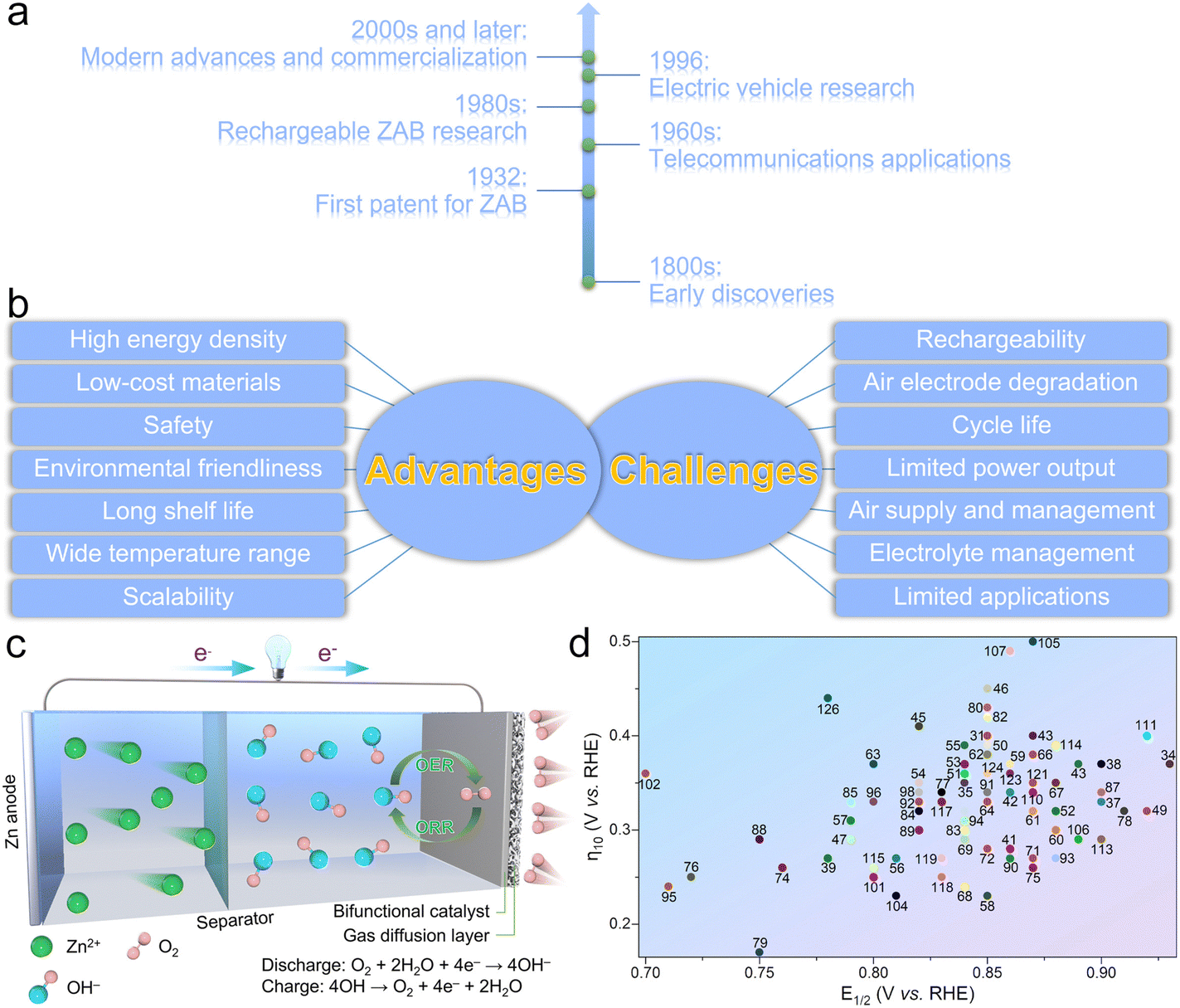 | ||
| Fig. 1 (a) Simple history of ZABs. (b) The advantages and challenges of ZABs. (c) Working diagram of the ZAB and the chemical reaction corresponding to the air electrode, as well as the catalytic diagram of the bifunctional catalyst. (d) The ORR (E1/2) and OER (η10) activities of bifunctional catalysts reported in recent years (the numbers are the references). | ||
While ZABs offer many merits, they also face several challenges and limitations that have hindered their widespread adoption (Fig. 1b),14–19 including: (1) rechargeability – one of the primary challenges of ZABs is achieving reliable and practical rechargeability. During discharge, zinc reacts with oxygen in air to produce electricity and zinc oxide. However, during the charging process, it is difficult to reverse this reaction and convert zinc oxide back to metallic zinc without causing dendrite formation and electrode degradation. Dendrites are branched structures that can grow on the zinc electrode surface, reducing battery performance over time and also leading to safety issues like short-circuiting; (2) cycle life – the formation of dendrites and the gradual degradation of the air electrode can lead to reduced cycle life, restricting their use in long-term applications like EVs; (3) air electrode degradation – the air electrode is critical for the operation of ZABs, as it facilitates the oxygen reduction reaction (ORR) during discharge. However, this electrode is susceptible to degradation over time due to exposure to oxygen, moisture, and electrochemical processes, which would cause a decline in battery performance and efficiency; (4) limited power output: ZABs generally have a lower power output compared to other battery technologies like lithium-ion batteries. This limitation makes them less suitable for applications that require high-power bursts, such as EVs and certain electronic devices; (5) air supply and management; appropriate air supply and management are crucial for the efficient operation of ZABs. If air access is restricted or oxygen flow is not adequately managed within the battery, it can lower the reaction activity and reduce energy output; (6) electrolyte management: the electrolyte in ZABs must be carefully managed to prevent the drying out of the battery or the leakage of electrolyte, which can negatively impact battery performance; and (7) limited applications – ZABs are best suited for specific applications, such as hearing aids, where small and lightweight batteries with high energy densities are required. Their rechargeability and power output limitations have impeded their use in broader applications like EVs and grid storage. Despite these challenges, ongoing research and development efforts are dedicated to addressing these issues and improving the performance and usability of ZABs. Advances in materials, catalysts, and engineering approaches are expected to address some of these issues and make ZABs more viable for multifarious applications, for example, renewable energy storage, electric vehicles, and so on.
As a crucial part required for the ORR and oxygen evolution reaction (OER), the air cathode would directly affect the electrochemical performance of ZABs.20,21 The efficiency and kinetics of the ORR and OER reactions highly depend on the catalyst used at the air electrode. Therefore, finding cost-effective and durable catalysts that enhance the reaction kinetics and resist deactivation would lead to increased power output and faster charge/discharge rates for ZABs. In this review, research on bifunctional catalysts that promote both ORR and OER activities during charging and discharging processes in the past five years will be comprehensively summarized, including structural design, component regulation, mechanism exploration, etc. At the same time, the functioning principle of the bidirectional catalysts will be introduced in detail. Finally, the prospective developments in the design of bifunctional catalysts and discussion about certain critical issues that necessitate consideration in the context of bifunctional catalyst development will be provided. This review aims to provide an effective reference for the application of bifunctional catalysts in ZABs and offers a theoretical basis for the future development of bifunctional catalysts for the practical and high-performance ZABs.
2. Mechanism of bifunctional catalysts for enhanced oxygen kinetics
ZABs rely on the electrochemical reactions between zinc and oxygen to deliver electrical energy (Fig. 1c). The basic components of ZABs include the Zn anode, air cathode, electrolyte and separator. During the discharge process, the Zn metal anode undergoes an oxidation reaction, releasing electrons and forming Zn2+ according to eqn (1) and (2):22–24| Zn + 4OH− ↔ Zn(OH)42− + 2e− | (1) |
| Zn(OH)42− ↔ ZnO + H2O + 2OH− | (2) |
At the cathode, O2 in air is reduced by accepting the electrons from the anode. The ORR produces hydroxide ions (OH−) in an alkaline electrolyte:
| O2 + 2H2O + 4e− ↔ 4OH− | (3) |
The combination of the anode and cathode reactions results in the overall reaction for the discharge process, which can be written as eqn (4):
| 2Zn + O2 ↔ 2ZnO | (4) |
In this reaction, zinc reacts with oxygen in air to form zinc oxide (ZnO). Simultaneously, electrical energy is generated as electrons flow from the anode to the cathode through an external circuit.
During the charge process, an external electrical source supplies the voltage, causing the OER to occur at the cathode according to the opposite direction of eqn (2). At the anode, the formed ZnO undergoes a reduction reaction to regenerate Zn metal according to the opposite direction of eqn (1). So, the overall reaction for the charge process can be written in the opposite direction of eqn (3), and the electrical energy from an external source is converted into chemical energy as Zn is redeposited and O2 is evolved on the anode and cathode, respectively.25,26
In ZABs, the ORR and OER are critical electrochemical processes that involve the conversion of O2 in air. These reactions occur at the air cathode during the discharge and charge processes, respectively. Undoubtedly, the ORR and OER catalysts play essential roles in facilitating these reactions, improving the battery's overall efficiencies, performances, and rechargeability. During the discharge process, the ORR is a critical step. It involves the reduction of O2 in air, resulting in OH− formation at the air electrode. The standard 4e− pathway of the ORR under alkaline conditions can be summarized by the following steps (* represents the active sites):27–30
| *O2 + H2O + e− → *OOH + OH− | (5) |
| *OOH + e− → *O + OH− | (6) |
| *O + H2O + e− → *OH + OH− | (7) |
| *OH + e− → * + OH− | (8) |
Moreover, in view of different numbers of electrons transferred, there is another ORR pathway of the 2e− reduction process according to eqn (9)–(11), which would generate HO2− species and is primarily used to produce hydrogen peroxide.31,32 In ZABs, the formation of hydrogen peroxide is generally undesirable because it could contribute to the degradation of the battery components, leading to a decline in stability, and reduce its operating potential and current efficiency.33,34 Therefore, catalyst design and operational conditions are typically optimized to reduce the 2e− reaction in the ORR. These strategies mainly include selecting an appropriate catalyst, tuning catalyst composition, surface structure and electronic properties, and optimizing the operational conditions such as temperature, pressure and electrolyte composition.35–38
| O2 + H2O + 2e− → HO2− + OH− | (9) |
followed by either further reduction reaction:
| HO2− + H2O + 2e → 3OH− | (10) |
or disproportionation:
| 2HO2− → 2OH− + O2 | (11) |
Generally, the ORR is inherently slow, especially when O2 directly reacts with water, which would lead to performance limitations, such as poor power output and efficiency. To overcome this, ORR catalysts are introduced at the air electrode to expedite the oxygen reduction process, which can facilitate the electron/proton transfer and increase the ORR kinetics, allowing for more efficient and rapid conversion of O2 into OH−. As a result, the presence of ORR catalysts can reduce the overpotential that drives the ORR reaction. This, in turn, improves the overall discharge performance and power delivery.
During the charge process, the OER is a critical step in the overall reaction, which involves the OH− oxidation to produce O2 and H2O at the air electrode. The standard 4e− pathway for the OER is in the opposite direction of the ORR. Similar to the ORR, the speed of the OER process is also slow, resulting in the limited battery's rechargeability and efficiency. So, OER catalysts are also indispensable for the air electrode to accelerate the oxygen evolution process, which can facilitate the electron/proton transfer and increase the kinetics of the OER to enable a more efficient and rapid conversion of OH− into O2 and lower the overpotential of the OER.6,23,24
Both ORR and OER catalysts play pivotal roles in the efficient operation of ZABs. By accelerating the oxygen reduction and evolution reactions, respectively, these catalysts would enhance the battery's discharge performance, rechargeability, and overall energy conversion efficiency. Therefore, ongoing research and development efforts focus on optimizing and finding cost-effective bifunctional catalysts that have both ORR and OER catalytic activities, to further improve the performance and commercial viability of ZABs (Fig. 1d). Here, several types of bifunctional catalysts for the air electrode in ZABs have been analyzed, including single metal components, multiple metal components and metal-free carbonaceous materials, all of which show enhanced oxygen-involved catalysis and deliver high performances when applied to construct the air cathode in a practical ZAB (Table 1).
| Catalyst | E 1/2 (V) | η 10 (V) | PPDc (mW cm−2) | Capacity (mA h g−1)/current (mA cm−2) | OCVd (V) | Ref. |
|---|---|---|---|---|---|---|
| a E 1/2 is the ORR half-wave potential. b η 10 is the overpotential at 10 mA cm−2 for the OER. c PPD refers to the peak power density. d OCV refers to the open-circuit voltage. | ||||||
| Fe–N@WPC | 0.85 | 0.40 | 70.20 | 735.6/10 | 1.53 | 39 |
| Fe–Nx–C | 0.86 | 0.57 | 181.17 | — | 1.41 | 40 |
| Fe–N4@G | 0.89 | 0.37 | 179.00 | — | — | 41 |
| Fe–Nx@SWCNT | 0.93 | 0.37 | 210.00 | 772.0 | 1.47 | 43 |
| Fe–N4@BC | 0.84 | 0.35 | 177.00 | 800.0/10 | 1.43 | 47 |
| Fe–N4@NSCF | 0.89 | 0.57 | 255.84 | — | 1.38 | 48 |
| Fe–N4@NPC | 0.90 | 0.33 | 120.00 | 585.0/10 | 1.45 | 49 |
| Fe–N/FePx/NPSC | 0.90 | 0.37 | 216.88 | 729.2/20 | 1.49 | 50 |
| FeS/Fe3C@NSC | 0.78 | 0.27 | 90.90 | 750.0/2 | 1.45 | 52 |
| FeP/Fe2O3@NPCA | 0.83 | 0.34 | 130.00 | 648.0/20 | 1.42 | 54 |
| CoNP@NCNTA | 0.86 | 0.28 | 38.60 | 770.0/10 | 1.48 | 61 |
| CoNP@NCNT | 0.86 | 0.34 | 133.00 | 777.0/10 | 1.52 | 62 |
| Co@hNCT | 0.87 | 0.40 | 149.00 | 746.0/10 | 1.45 | 63 |
| CoNP@NCNF | 0.85 | 0.28 | 292.00 | 322.3 | 1.59 | 64 |
| Co4N@NC | 0.79 | 0.29 | 74.30 | 769.4/5 | 1.46 | 65 |
| Co/Co3O4@NC | 0.92 | 0.32 | 123.50 | — | 1.50 | 66 |
| Co/CoO@NWC | 0.85 | 0.39 | 152.80 | 800.0/10 | 1.42 | 67 |
| CoOx@NC | 0.88 | 0.32 | 157.10 | 887.0/10 | 1.49 | 68 |
| Co3O4−x/NG | 0.84 | 0.37 | 166.00 | 700.6/10 | 1.49 | 69 |
| CoS/CoO@NG | 0.84 | 0.39 | 137.80 | 723.9/20 | 1.45 | 70 |
| CoNP@CNW | 0.82 | 0.41 | 304.00 | 762.0/10 | 1.46 | 72 |
| CoNP@PTCOF | 0.85 | 0.45 | 53.00 | 796.9/10 | — | 73 |
| Mn–CoN | 0.65 | 0.39 | 53.00 | — | 1.55 | 74 |
| ODAC-CoO | 0.84 | 0.36 | 128.50 | 705.6/20 | 1.45 | 75 |
| V–Co3O4 | 0.82 | 0.35 | 120.30 | 814.0/5 | 1.45 | 76 |
| N–CoS2@YSS | 0.81 | 0.27 | 81.00 | 744.0/5 | 1.41 | 80 |
| CoS/CoS2@NCNT | 0.79 | 0.31 | 131.00 | — | 1.45 | 81 |
| Pt/CoS2@NrGO | 0.85 | 0.23 | 114.00 | 763.0/10 | 1.41 | 82 |
| CoO/CoxP | 0.86 | 0.37 | 122.70 | — | 1.40 | 83 |
| Co2P@NC | 0.88 | 0.30 | 81.30 | — | 1.44 | 84 |
| Co/Co2P@NCNT | 0.87 | 0.32 | 330.00 | — | 1.45 | 85 |
| CoSA@NCNF | 0.85 | 0.38 | 154.50 | 796.0/10 | 1.53 | 86 |
| NCF | 0.80 | 0.37 | 185.00 | 775.0/5 | 1.48 | 87 |
| ZOMC | 0.85 | 0.33 | 221.10 | 753.9/10 | 1.49 | 88 |
| CNFM | 0.84 | 0.32 | 60.30 | — | 1.46 | 89 |
| CoSA@CNT/NCP | 0.87 | 0.38 | 172.00 | 864.8/5 | 1.45 | 91 |
| CoNC-NB | 0.88 | 0.35 | 246.00 | — | 1.50 | 92 |
| CoNC@LDH | 0.84 | 0.24 | 173.00 | 800.0/25 | — | 93 |
| CoNP@CoNC | 0.84 | 0.29 | 188.80 | 794.1/10 | 1.46 | 94 |
| CoSA@NDG | 0.87 | 0.35 | 251.40 | 757.4/10 | 1.53 | 95 |
| NiSA@NC | 0.85 | 0.28 | 165.00 | — | 1.43 | 97 |
| Ni/Ni–N–C | 0.88 | 0.30 | 181.00 | 741.0/10 | — | 98 |
| Ni/NiO | 0.76 | 0.26 | 225.00 | 853.0/20 | 1.47 | 100 |
| NiNP@NC | 0.87 | 0.26 | 117.10 | 706.0/10 | 1.49 | 101 |
| N–NiS1.03HS | 0.72 | 0.25 | 93.90 | 821.0/10 | 1.41 | 102 |
| CoSe2@NC | 0.83 | 0.34 | 137.10 | 751.1/10 | 1.31 | 106 |
| CuSA@HNCNx | 0.91 | 0.32 | 212.00 | 806.0/10 | 1.51 | 108 |
| Ru–RuO2@NPG | 0.75 | 0.17 | 137.00 | — | 1.48 | 109 |
| FeCoAL | 0.85 | 0.43 | 199.20 | 798.3/10 | 1.39 | 113 |
| FeCoAL@CNF | 0.90 | 0.37 | 160.00 | 745.0/10 | 1.49 | 114 |
| FeCo2AL@NC | 0.85 | 0.42 | 423.70 | 812.5/20 | 1.45 | 116 |
| Co/FeCo@NC | 0.84 | 0.30 | 146.60 | 775.5/10 | 1.49 | 117 |
| FeCoAL@NSC | 0.82 | 0.32 | 162.70 | 776.0/15 | 1.45 | 120 |
| FeCo/Co2P@NPCNF | 0.79 | 0.33 | 154.00 | — | 1.44 | 121 |
| FeCoN@NCNT | 0.84 | 0.32 | 145.00 | 778.4/10 | 1.45 | 122 |
| FeCoAL@SeCNT | 0.90 | 0.34 | 173.00 | 745.0/10 | 1.54 | 123 |
| FeNiAL@NCNT | 0.75 | 0.29 | 300.70 | 772.3/10 | 1.48 | 124 |
| FeNiAL@NCF | 0.82 | 0.30 | 102.00 | 729.0/10 | 1.40 | 125 |
| FeNi3AL@NC | 0.86 | 0.27 | 139.00 | — | 1.39 | 126 |
| FeNiAL@NLCN | 0.85 | 0.34 | 162.00 | 831.0/5 | 1.49 | 127 |
| CoNiAL@NCNT | 0.82 | 0.33 | 138.00 | 782.0/5 | 1.47 | 128 |
| PtCoF | 0.88 | 0.27 | 125.00 | 808.0/10 | 13.1 | 130 |
| FeNiCoP@NC | 0.84 | 0.31 | 112.00 | 807.0/10 | 1.36 | 133 |
| AlFeCoNiCr | 0.71 | 0.24 | 125.00 | 800.0/20 | 1.55 | 134 |
| α-MnOx/TiC | 0.80 | 0.33 | 217.10 | 769.8/10 | 1.35 | 147 |
| Co/ZnCo2O4@NCNT | 0.90 | 0.37 | 305.00 | 922.0/20 | 1.47 | 149 |
| NiMnCo@AC | 0.82 | 0.34 | 187.70 | 794.1/10 | 1.43 | 150 |
| PdNiMnO-PF | 0.84 | 0.36 | 211.60 | 812.9/10 | 1.37 | 151 |
| Mn–RuO2 | 0.86 | 0.27 | 181.00 | 812.0/10 | 1.55 | 155 |
| RuCoOx | 0.80 | 0.25 | 185.00 | 807.0/10 | — | 158 |
| S-LCO | 0.70 | 0.36 | 92.00 | 747.0/5 | 1.47 | 159 |
| LDH-POF | 0.80 | 0.25 | 185.00 | 807.0/10 | — | 160 |
| NiS/NiFe2O4 | 0.81 | 0.23 | 148.50 | — | 1.45 | 161 |
| Fe–Co@CNF | 0.87 | 0.50 | 201.70 | 814.0/10 | 1.45 | 162 |
| Fe–Co@NCAG | 0.89 | 0.29 | 117.00 | — | 1.47 | 163 |
| Fe–Co@NSCS | 0.86 | 0.49 | 76.50 | 636.3/10 | 1.34 | 167 |
| Fe–Co@NCS | 0.86 | 0.36 | 86.65 | 819.6/5 | 1.43 | 168 |
| Fe–Co@NC | 0.89 | 0.37 | 150.00 | 518.0/10 | 1.39 | 169 |
| Fe–Co@NC | 0.87 | 0.34 | 372.00 | — | 1.47 | 172 |
| Fe–Mn@NC | 0.92 | 0.40 | 184.00 | 734.0/2 | 1.45 | 173 |
| Fe–Ni@DNSC | 0.88 | 0.35 | 160.00 | 802.5/10 | — | 174 |
| Fe–Ni@NC | 0.90 | 0.29 | 260.00 | 950.0/5 | 1.54 | 175 |
| Co–Ni@PNC | 0.88 | 0.39 | 252.00 | 874.0/100 | 1.59 | 177 |
| Cu–CoFS | 0.80 | 0.26 | 255.00 | — | 1.44 | 178 |
| CuCoNC@Cu | 0.84 | 0.24 | 140.00 | 804.0/5 | 1.40 | 179 |
| FeCoMoS@NG | 0.83 | 0.33 | 118.00 | 789.0/10 | 1.44 | 181 |
| Ni–Co9S8@rGN | 0.83 | 0.25 | 171.50 | — | 1.37 | 185 |
| CoP–NC@FeNiP | 0.83 | 0.27 | 93.00 | — | 1.44 | 189 |
| FeNiP@NPC | 0.84 | 0.31 | 163.00 | — | 1.51 | 190 |
| Ni3FeN/VN@NG | 0.87 | 0.35 | 168.00 | 651.0/20 | 1.52 | 191 |
| MoS2@Fe–N–C | 0.84 | 0.36 | 78.00 | 442.0/5 | 1.47 | 192 |
| GNCNT | 0.86 | 0.36 | 253.00 | 801.0/5 | 1.48 | 195 |
| NCNTM | 0.85 | 0.36 | 220.00 | 716.0/10 | 1.50 | 196 |
| N-CNSP | 0.85 | 0.39 | 160.00 | — | 1.48 | 197 |
| NSC | 0.78 | 0.44 | 94.80 | — | 1.39 | 198 |
| NOS-ASP | 0.84 | 0.31 | 235.00 | 750.0/10 | 1.50 | 199 |
3. Advanced bifunctional catalyst design
In the past five years, the research on ZABs has been extensively reported, and the accompanying bifunctional catalysts have been designed in large quantities, and their catalytic mechanism has also been deeply explored. Based on this, partially selected catalyst materials are divided into three categories according to their characteristics. For each category, more detailed classification and analysis are shown below (Fig. 2):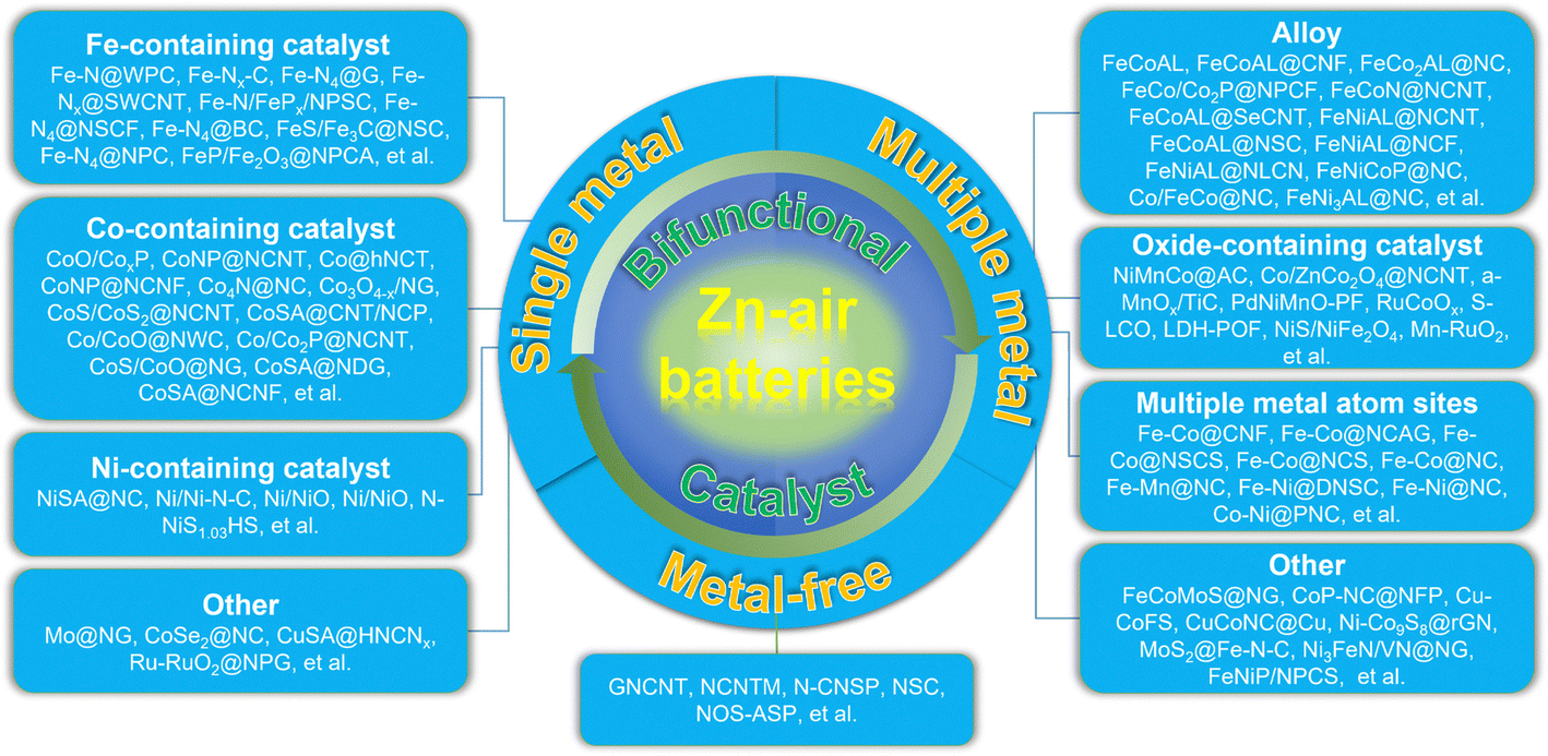 | ||
| Fig. 2 An overall diagram of selected bifunctional catalysts for advanced ZABs. | ||
3.1. Single metal components
Single metal component based bifunctional catalysts play a crucial role in the ORR and OER due to their improved performance, cost-effectiveness, stability, enhanced electrocatalytic activity, environmental friendliness, and flexibility in catalyst design. As a typical representative, single metal atom catalysts (SMACs) can exhibit bifunctional catalytic activity through several mechanisms, leveraging the unique properties of individual metal sites. Here may be some ways in which SMACs demonstrate bifunctional catalysis:21,23,25,31,39 (1) electronic structure tuning – single metal atoms on a support material often have distinct electronic structures compared to bulk metal catalysts, which enable them to participate in different catalytic reactions simultaneously, including oxidation and reduction reactions; (2) dual active sites – single metal atoms can possess multiple types of active sites on the same metal atom, which may have different catalytic functionalities, allowing the SMACs to catalyze more than one type of chemical transformation, thus contributing to bifunctional catalytic activity; (3) cooperative catalysis – SMACs may engage in cooperative interactions between the metal site and the support material. The support can provide acidic or basic sites, while the metal atom facilitates redox reactions. The synergy between these functionalities allows the catalyst to mediate both acid–base and redox reactions simultaneously; (4) site isolation and selectivity. The isolation of active sites on single metal atoms can enhance selectivity by preventing undesired side reactions, which can precisely control the reaction environment and allow the SMAC to catalyze multiple reactions with high selectivity, therefore contributing to its bifunctional activity; (5) tailored ligands – some SMACs involve the use of ligands attached to the metal atom. These ligands can be tailored to provide specific catalytic functionalities, allowing the catalyst to participate in multiple types of reactions. Ligand design plays a crucial role in determining the bifunctional catalytic activity of SMACs; (6) synergistic effects – the presence of a single metal atom on a support material can lead to synergistic effects between the metal and the support, which can result in enhanced catalytic activity, making the catalyst suitable for bifunctional catalysis. The combination of different catalytic functionalities contributes to the overall bifunctional performance; and (7) redox chemistry: SMACs often exhibit redox activity, allowing them to participate in both oxidation and reduction reactions. The redox properties of the metal site enable the catalysis of diverse chemical transformations, contributing to the bifunctional nature of the catalyst. Therefore, the bifunctional catalytic activity of single metal atom catalysts arises from a combination of factors, including electronic structure tuning, dual active sites, cooperative catalysis, site isolation and selectivity, tailored ligands, synergistic effects, and redox chemistry. These catalysts offer a versatile platform for designing efficient and selective catalysts for a wide range of chemical transformations. The specific mechanisms will depend on the nature of the metal, the support material, and the target reactions. Here, the single metal component based bifunctional catalysts are mainly divided into Fe-containing, Co-containing, Ni-containing, and other types, all of which show high catalytic activity for the ORR and OER.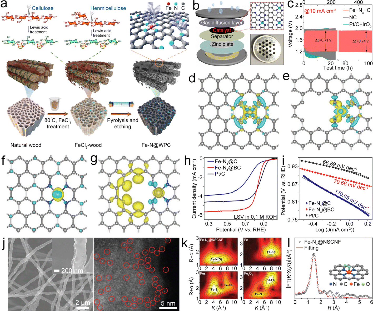 | ||
| Fig. 3 (a) Diagram of the synthesis of Fe–N@WPC. Reproduced with permission from ref. 39. Copyright 2021, American Chemical Society. (b) Diagram of the coin-type ZAB. (c) Cycling performance of as-prepared catalyst-based air cathodes. Reproduced with permission from ref. 40. Copyright 2022, Elsevier. (d) and (e) Charge density difference of Fe–N4 in-plane and edge sites. (f) and (g) Spin density of Fe–N4 in-plane and edge sites. Reproduced with permission from ref. 41. Copyright 2020, Wiley-VCH. (h) and (i) LSV and Tafel plots of as-prepared catalyst-based working electrodes. Reproduced with permission from ref. 47. Copyright 2022, Elsevier. (j) Scanning electron microscopy (SEM) and high angle annular dark field scanning transmission electron microscopy (HAADF-STEM) images of the Fe–N4@NSCNF catalyst. (k) Wavelet transforms of the EXAFS spectra of the Fe K-edge of different catalysts. (l) The corresponding fitting curve of the Fourier-transform EXAFS spectra of the Fe–N4@NSCNF catalyst. Reproduced with permission from ref. 48. Copyright 2022, Wiley-VCH. | ||
In situ generated Fe clusters could facilitate the deposition of Fe–N4 moieties, leading to the Fe–N4 edge site being formed in graphene (Fe–N4@G).41 Compared to the in-plane site, the Fe–N4 edge site has a low coordination number of edge N, resulting in the charge redistribution and enhanced electron transfer from the Fe atom to the neighboring N atom (Fig. 3d–g), thus boosting oxygen-involved electrocatalysis.42 Moreover, the electronic structure on the edge site can regulate the adsorption/desorption of oxygen intermediates and display higher adsorption free energy for OH* and reduced energy barrier for the rate-determining step (RDS), resulting in high ORR/OER activity. The resultant ZAB with the Fe–N4@G catalyst exhibited a decreased ΔV of 0.78 V and good cycling stability. This research provides a valuable reference for the incorporation of Fe–N4 sites into graphene. Similarly, Fe–Nx–C moieties can also be anchored on a single-walled carbon nanotube (Fe–Nx@SWCNT) film, in which the SWCNT possesses rich Fe–Nx–C active sites while maintaining high crystallinity and good flexibility,43 which endow the Fe–Nx@SWCNT catalyst with enhanced electron/mass transport paths, high catalytic activities, and good flexibility, leading to a high PPD of 210 mW cm−2, along with a high capacity of 772 mA h g−1, for the ZAB. Furthermore, Fe–Nx@SWCNT could enable an all-solid-state flexible ZAB to show a stabilized open circuit voltage (OCV) even at different bending angles. This study combines high conductivity SWCNTs and highly active Fe–Nx–C, which offer a valuable reference for the application of CNTs in the bifunctional catalysts.
Doping of heteroatoms (N, P, S, B, etc.) on the carbon backbone has been reported to adjust the electronic configuration of the Fe–N4–C based catalyst, thereby decreasing the energy barrier of the RDS and increasing the electrocatalytic activity.44–46 Zhao et al. anchored Fe–N4–C in a B-doped carbon matrix (Fe–N4@BC).47 B doping can adjust the electronic configuration of Fe–N4–C, which assists in the breaking of the O![[double bond, length as m-dash]](https://www.rsc.org/images/entities/char_e001.gif) O bond and thus lowers the RDS energy barrier, resulting in a small Tafel slope and a high E1/2 of 0.84 V (Fig. 3h and i) under alkaline conditions. Even in acidic media, the E1/2 only reaches as high as 0.81 V. N,S-co-doped carbon nanofibers (CNFs) with high-density loading Fe–N4–C active sites (Fe–N4@NSCNF) can be synthesized by electrospinning and pyrolysis.48 The obtained Fe–N4@NSCNF (Fig. 3j) catalyst with a highly porous structure and high surface area can accelerate reactant infiltration and realize high loading density of Fe–N4–C sites. What's more, the NSCNF matrix can also adjust the electronic structure of Fe–N4–C, enabling high oxygen electrocatalytic activities. Moreover, Fe atoms with +2 and +3 valencies could be coordinated with neighboring N/O (Fig. 3k) with a coordination number of about 5 (Fig. 3l), including 4 neighboring N atoms and 1 adsorbed O atom. Benefitting from these unique properties, the Fe–N4@NSCNF composite demonstrated enhanced ORR/OER activities, resulting in the ZAB exhibiting a long cycle life of over 1000 h. This research provides deeper insight into the effect of heteroatom doping on enhancing the catalytic performance of the Fe–N4–C site. In addition to the above catalysts, the Fe–N4–C active site was also designed in the N, P co-doped carbon,49 Fe, N, P, S co-doped porous carbon,50etc., all of which show a similar function of modulating the electronic structure for enhanced catalysis at the Fe–N4–C active site.
O bond and thus lowers the RDS energy barrier, resulting in a small Tafel slope and a high E1/2 of 0.84 V (Fig. 3h and i) under alkaline conditions. Even in acidic media, the E1/2 only reaches as high as 0.81 V. N,S-co-doped carbon nanofibers (CNFs) with high-density loading Fe–N4–C active sites (Fe–N4@NSCNF) can be synthesized by electrospinning and pyrolysis.48 The obtained Fe–N4@NSCNF (Fig. 3j) catalyst with a highly porous structure and high surface area can accelerate reactant infiltration and realize high loading density of Fe–N4–C sites. What's more, the NSCNF matrix can also adjust the electronic structure of Fe–N4–C, enabling high oxygen electrocatalytic activities. Moreover, Fe atoms with +2 and +3 valencies could be coordinated with neighboring N/O (Fig. 3k) with a coordination number of about 5 (Fig. 3l), including 4 neighboring N atoms and 1 adsorbed O atom. Benefitting from these unique properties, the Fe–N4@NSCNF composite demonstrated enhanced ORR/OER activities, resulting in the ZAB exhibiting a long cycle life of over 1000 h. This research provides deeper insight into the effect of heteroatom doping on enhancing the catalytic performance of the Fe–N4–C site. In addition to the above catalysts, the Fe–N4–C active site was also designed in the N, P co-doped carbon,49 Fe, N, P, S co-doped porous carbon,50etc., all of which show a similar function of modulating the electronic structure for enhanced catalysis at the Fe–N4–C active site.
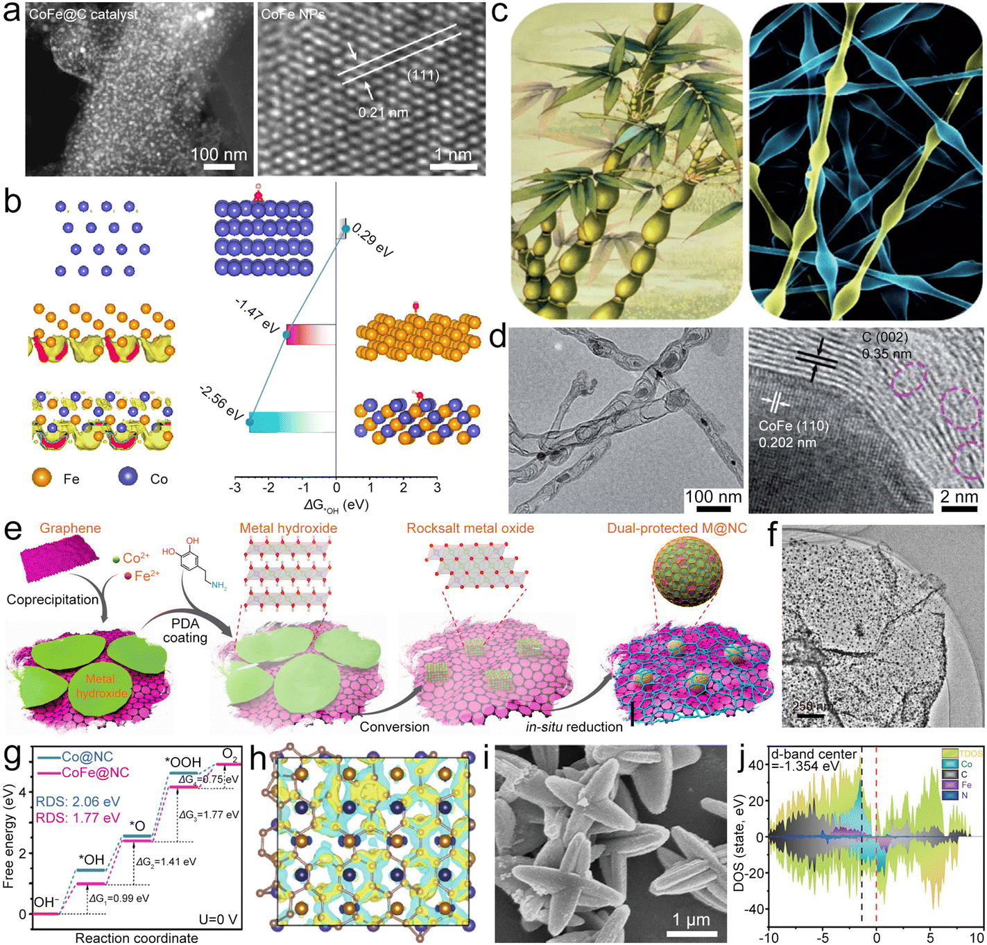
Fe-based compounds (Fe3C, Fe2O3, Fe5C2, FeS, Fe3C, and so on) combined with Fe–Nx–C moieties show synergistic catalysis, thus realizing superior bifunctional catalytic activities. Fe/Fe3C nanocrystals composited with Fe–Nx–C moieties served as a bifunctional catalyst (Fe/Fe3C@Fe–Nx–C) for the ZAB.51 The synergistic catalysis of Fe–Nx–C moieties and Fe/Fe3C nanoparticles (NPs) enables a high E1/2 of 0.9 V for the ORR and a small η10 of 0.41 V for the OER. The ZAB with the Fe/Fe3C@Fe–Nx–C catalyst thus showed a high PPD of ∼147 mW cm−2 and remarkable stability. In addition, Fe-based compounds can also be directly designed as catalysts for ZABs. Li et al. fabricated FeS/Fe3C NPs encapsulated in the N,S-co-doped carbon (FeS/Fe3C@NSC) as a bifunctional electrocatalyst for the ZAB, which showed a small ΔE of 0.72 V, resulting in high PPD and specific capacity for the ZAB.52 Fe3C quantum dots can be loaded in N-doped carbon mesoporous spheres (Fe3C@NCMS) as the catalyst for the ZAB (Fig. 4a).53 Based on the Mott–Schottky effect of the Fe3C–NG heterojunction, the Fe3C@NCMS (Fig. 4b) catalyst enables rapid electron transfer from Fe3C to NG due to the difference in work function (Fig. 4c), leading to electronic distribution and accelerated charge transfer of ORR/OER processes (Fig. 4d and e). Besides, the heterojunction interface could adjust the adsorption strength of intermediates and lower their energy barriers in the catalytic processes. Therefore, the Fe3C@NCMS showed promoted kinetics, achieving a ZAB with an energy density of 706.4 W h kg−1 and good cycling stability. In addition, a honeycomb-like N, P co-doped carbon aerogel with FeP/Fe2O3 (FeP/Fe2O3@NPCA) can be synthesized as a bifunctional electrocatalyst by directional freeze-casting and annealing (Fig. 4f).54 The carbon aerogel possesses porous architecture (Fig. 4g and h) to speed up the gas/electrolyte diffusion and improve ionic conductivity. Therefore, high ORR/OER activities (Fig. 4i) can be simultaneously realized via synergy between FeP/Fe2O3 and NPCA. The FeP/Fe2O3@NPCA based ZAB (Fig. 4j) could exhibit high capacity and superior cycling stability, as well as good flexibility. These studies indicate that Fe-based compounds have great application potential in the field of bifunctional oxygen catalysts for ZABs. However, it should be noted that the metal compounds, such as hydroxides, chalcogenides, phosphides and nitrides, would undergo surface reconstruction that is accompanied by the transformation of valence states during the electrolytic processes. This phenomenon would result in changes in active sites, improving or reducing catalytic performance. In most cases, these metal compounds act as “pre-catalysts” rather than the “real catalysts”.55–58 Therefore, understanding the reconstruction process and precisely identifying the true active sites on electrocatalyst surfaces will help to finely tune the properties and activities of catalysts.
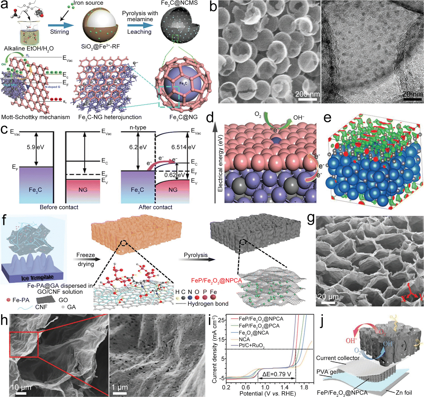 | ||
| Fig. 4 (a) Diagram of the synthesis of Fe3C@NCMS and the Fe3C–NG heterojunction. (b) SEM and high-resolution TEM (HRTEM) images of Fe3C@NCMS. (c) Diagram of the Fe3C–NG heterojunction before and after contact. (d) ORR mechanism Fe3C–NG. (e) Charge distribution of the Fe3C–NG model. Reproduced with permission from ref. 53. Copyright 2022, Wiley-VCH. (f) Diagram of the preparation of the FeP/Fe2O3@NPCA catalyst. (g) and (h) SEM images of FeP/Fe2O3@NPCA. (i) Polarization curves of as-prepared catalysts with bifunctional catalytic activity. (j) Diagram of a solid-state ZAB based on the FeP/Fe2O3@NPCA cathode. Reproduced with permission from ref. 54. Copyright 2020, Wiley-VCH. | ||
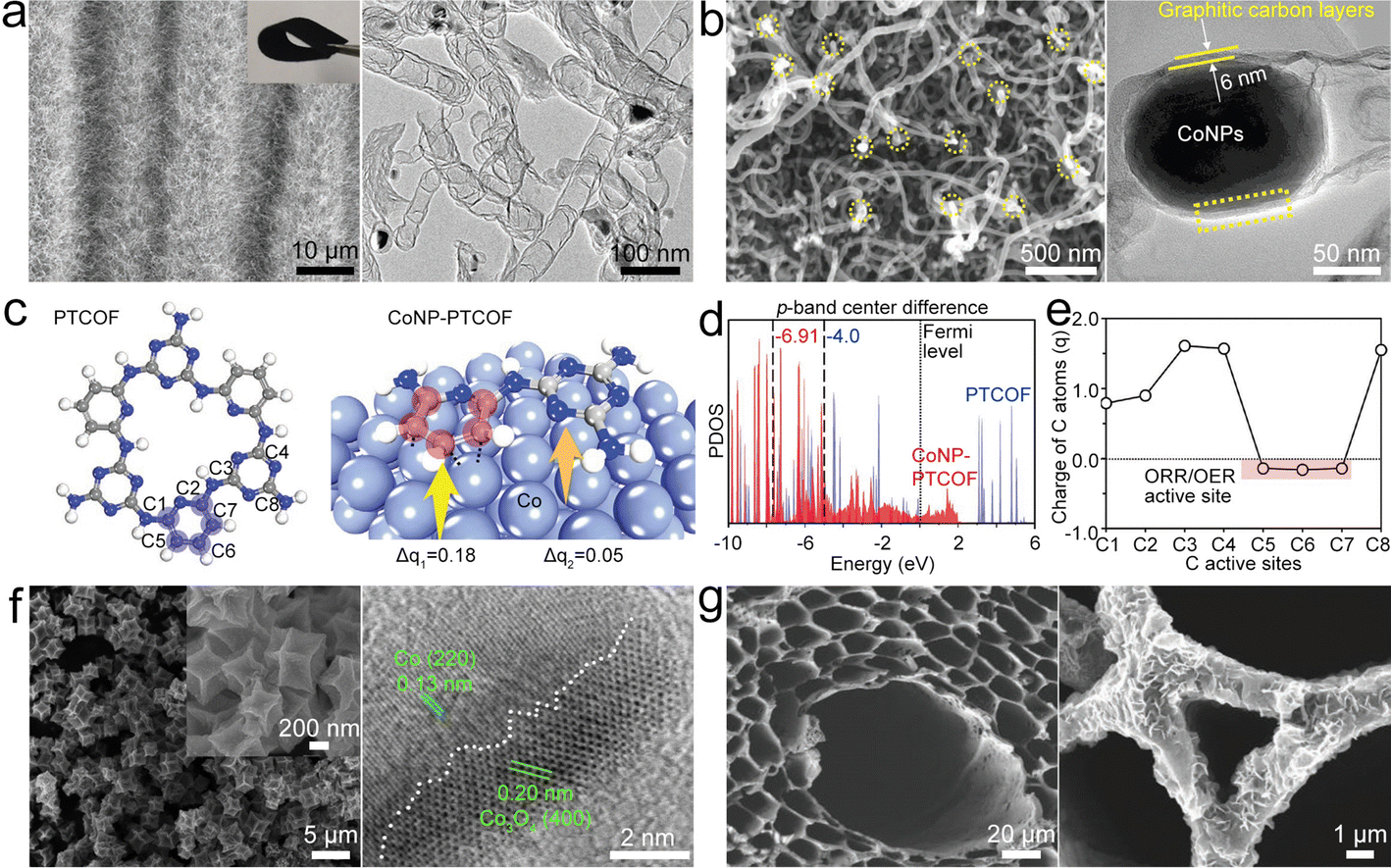 | ||
| Fig. 5 (a) SEM and TEM images of Co@NCNTA. Reproduced with permission from ref. 61. Copyright 2019, Wiley-VCH. (b) SEM and HRTEM images of CoNP@NCNT. Reproduced with permission from ref. 62. Copyright 2020, Wiley-VCH. (c) Structures of the periodic units of PTCOF and CoNP-PTCOF with electron charge quantity (q) transferred from the Co surface to the carbon repeating unit. (d) p-Band structures of PTCOF and CoNP-PTCOF. (e) Electron charge distribution on the C sites of the CoNP-PTCOF structure. Reproduced with permission from ref. 73. Copyright 2021, Wiley-VCH. (f) SEM and HRTEM images of Co/Co3O4@NC. Reproduced with permission from ref. 66. Copyright 2020, Elsevier. (g) SEM images of NWC and Co/CoO@NWC. Reproduced with permission from ref. 67. Copyright 2021, Wiley-VCH. | ||
Co NPs can be embedded into a pyridine-linked triazine covalent organic framework (PTCOF) as a bifunctional catalyst (CoNP@PTCOF) (Fig. 5c).73 Incorporating Co NPs will lead to the p-band center of C active sites shifting to a lower position (Fig. 5d) by accepting electrons from the Co surface, indicating that the C active sites have moderate *OH binding strength. In addition, the C atoms of the pyridine moiety have nearly neutral electronic states for ORR/OER processes (Fig. 5e), and thus the electrocatalytic activities of CoNP@PTCOF can be improved. To enhance the catalysis of Co NPs, NH3 atmosphere treatment was used to prepare Co4N NPs embedded in an N-doped carbon box (Co4N@NC).65 Co4N has increased electronic conductivity and reduced adsorption free energy at the RDS in the OER/ORR process, endowing the ZAB based on the Co4N@NC catalyst with high stability and a low ΔV of 0.85 V. It is further shown that Mn doping could boost the intrinsic ORR/OER activity of CoN via modulating the adsorption energies of intermediates.74 These studies illustrate the critical role of Co-based NPs in the field of bifunctional oxygen catalysts.
The Co NP and Co-based oxide composite can form a highly active hetero-interface that boosts the ORR/OER activities.59 For example, the Co/Co3O4 heterojunction in N-doped carbon (Co/Co3O4@NC) (Fig. 5f) can be fabricated as a bifunctional oxygen electrocatalyst, which has a three-phase combination of Co, Co3O4, and porous carbon with an optimal charge/mass transfer. In this structure, the Co/Co3O4 hetero-interfaces are the particular active sites boosting the ORR/OER kinetics,66 hence displaying high catalytic activity that is comparable to those of noble metal electrocatalysts. A similar design was also reported by Cui et al.,67 where they constructed Co/CoO NPs incorporated in N-doped wood-derived carbon (Co/CoO@NWC) (Fig. 5g). The different hydrophilicities of NWC and Co/CoO endow the catalyst with abundant triple-phase (solid/liquid/gas) boundaries for the battery reaction, which provide dominating active sites for oxygen reactions. Therefore, the Co/CoO@NWC catalyst displayed high catalytic activity and stability, resulting in the ZAB with a high PPD of 152.8 mW cm−2.
Single metal components of cobalt oxide could be used as catalysts for ZABs. Considering that incorporating O vacancies on the CoO surface could reduce the energy barrier at the RDS for the ORR/OER, O-defective amorphous-crystalline CoO (ODAC–CoO) was designed by vacuum-calcination of the Co(OH)2 precursor (Fig. 6a) as a bifunctional electrocatalyst.75 Due to the optimized crystallinity and moderate O vacancy level, the ODAC–CoO catalyst (Fig. 6b) exhibited increased bifunctional activity and stability and enabled the ZAB to deliver highly efficient and stable performance. Compared with CoOx with a larger size (Co26O5), downsizing the CoOx particle will induce charge accumulation, resulting in the electron orbital overlap with carbon.68 Moreover, CoOx coupling with Co–N would facilitate the electron cloud migration from CoOx to Co–N (Fig. 6c), shifting the d-band center of Co farther away from the Fermi level (Ef) (Fig. 6d) and moving the p-orbitals of O and N atoms near the Ef at the same time (Fig. 6e), which would optimize the desorption of oxygen intermediates and accelerate the ORR/OER catalytic process. Sub-nanometer CoOx confined into N-doped carbon (CoOx@NC) was prepared to combine the merits of reduced size and the Co–N moiety. CoOx@NC displayed reduced barriers at the ORR/OER, which can balance the adsorption/desorption of O2 and OH−, optimize the reaction path and accelerate ORR/OER reaction kinetics. Consequently, the CoOx@NC catalyst demonstrated a narrow ΔV of 0.67 V and impressive ZAB performances. To increase the ORR/OER activity of Co3O4, the Co3O4−x with N-doped graphene (Co3O4−x@NG) electrocatalyst having Co–N–C and adjustable O vacancy content was prepared by Qin et al.69 The synergistic effects of Co–N–C and its adjacent O vacancy can adjust the charge density of the O-vacant Co site, thereby regulating the adsorption energies of ORR/OER intermediates, resulting in a low ΔE of 0.66 V and enabling the ZAB with an energy density of 853.3 W h kg−1 as well as good stability. Rao et al. prepared vanadium (V4+ and V5+)-doped mesoporous Co3O4 nanorods (V–Co3O4) as bifunctional oxygen catalysts for ZABs.76 By incorporation of V element, the eg occupancy of Co3O4 can be optimized to balance the binding strength for oxygen intermediates in the RDS toward the ORR/OER, thus achieving a high catalytic activity. These studies indicate that Co-based oxides have important developmental potential in the field of bidirectional oxygen catalysts.
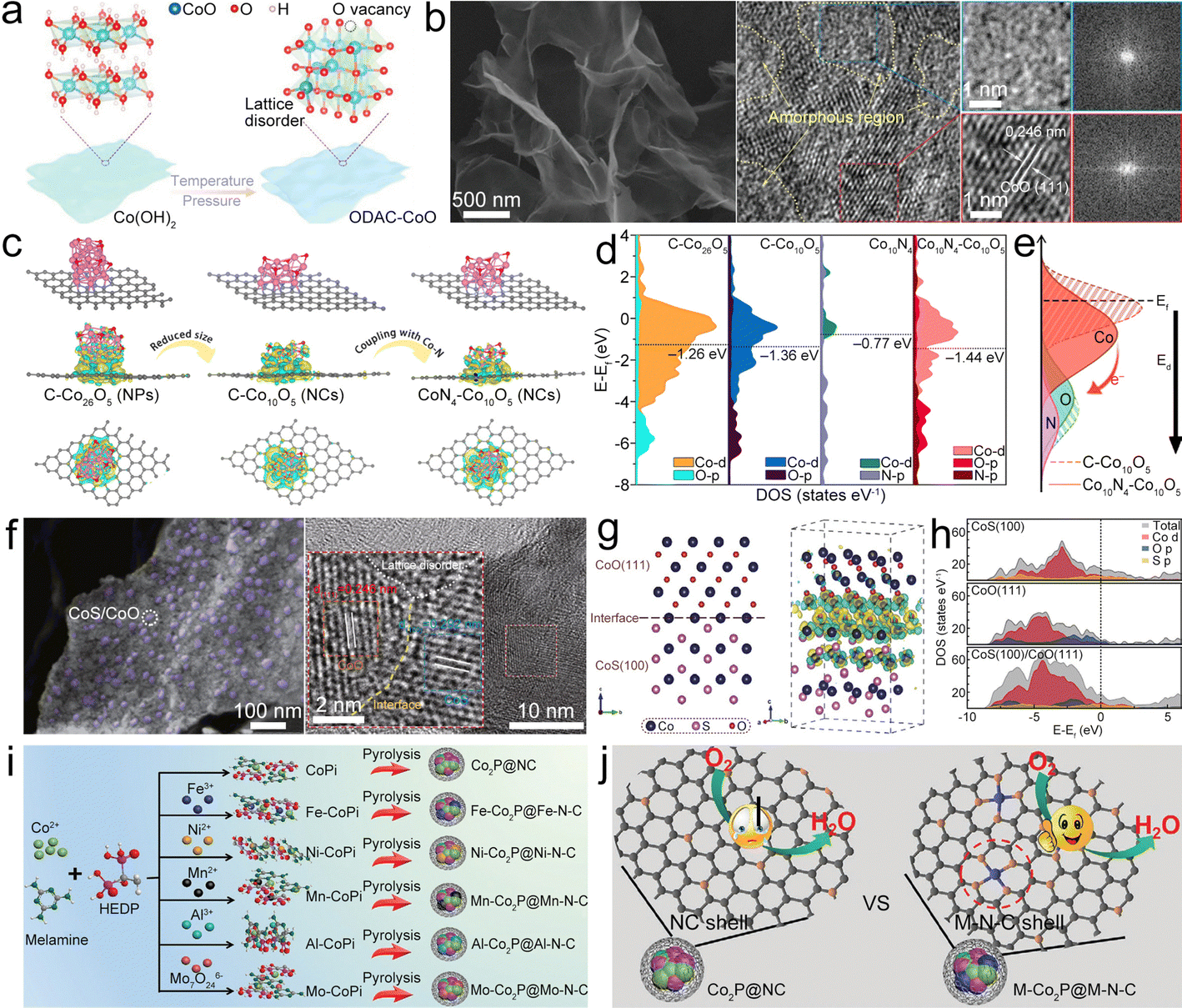 | ||
| Fig. 6 (a) Diagram of the synthesis of ODAC-CoO. (b) SEM and HRTEM images of ODAC-CoO. Reproduced with permission from ref. 75. Copyright 2021, Wiley-VCH. (c) Model structures and the charge density redistributions of CoN4–Co26O5, CoN4–Co10O5, and C–Co10O5. (d) DOS of CoN4–Co26O5, CoN4–Co10O5, C–Co10O5 model, and d-band centers. (e) Diagram of influence of coupling Co–N on the Co10O5 surface electronic structure. Reproduced with permission from ref. 68. Copyright 2021, Elsevier. (f) SEM and HRTEM images of CoS/CoO@NGN. (g) Schematic and contour plots of differential charge density of the CoS(100)/CoO(111) heterostructure model. The yellow and cyan regions represent the charge accumulation and charge depletion, respectively. (h) DOS plots of CoS(100), CoO(111) and CoS(100)/CoO(111). Reproduced with permission from ref. 70. Copyright 2020, Springer. (i) Diagram of the synthesis of M–Co2P@M–N–C catalysts. (j) Diagram of the ORR process catalyzed by the NC shell (Co2P@NC) and the M–N–C shell (M–Co2P@M–N–C). Reproduced with permission from ref. 84. Copyright 2021, Wiley-VCH. | ||
Cobalt sulfide could be used to enhance the ORR/OER activities of cobalt oxide. Tian et al. designed a heterostructure of CoS/CoO NPs on N-doped graphene (CoS/CoO@NG) (Fig. 6f) as the catalyst.70 At the interface of CoO and CoS, the charge redistribution would occur with the electron accumulated at the CoO side (Fig. 6g). CoS/CoO has increased density of states (DOS) near the Ef compared with CoS and CoO (Fig. 6h), suggesting that the CoS/CoO heterostructure possesses increased conductivity to enhance the electrocatalytic activity by promoting electron transfer between the absorbed intermediates and catalyst surface.77 After being composited with NG, the accumulation of electrons at the metal–support interface can decrease the contact resistance and realize the efficient electron transfer of CoS/CoO@NG, thus expediting the catalytic kinetics.78,79 Lu et al. fabricated the CoS/CoS2 NPs in NCNTs (CoS/CoS2@NCNT) as the bifunctional catalyst.80 The synergistic effects of multivalent cobalt sulfides and NCNTs could enhance the electron conduction and facilitate O2 activation, therefore improving the ORR activity. Moreover, the strong Co–N bond between CoSx NPs and NCNTs could build up unique hetero-interfaces, which can facilitate the interfacial electron transfer during the ORR/OER processes. Logeshwaran et al. anchored Pt NPs on CoS2 supported by N-doped reduced graphene oxide (rGO) to form the Pt/CoS2@NrGO nanohybrid.81 CoS2 on NrGO offers enhanced electron transfer and synergistic effects to enhance catalytic activity for the OER/ORR. Consequently, the Pt@CoS2–NrGO based ZAB delivered high PPD and high round-trip efficiency. Actually, there are many studies about the application of cobalt sulfides as ORR/OER catalysts for ZABs, such as Co9S8, CoS2 and their composites,71,80–82 P-doped Co9S8 embedded in carbon spheres (P-Co9S8@CS),71 N-doped CoS2 yolk–shell spheres (N–CoS2@YSS),82 and so on.
Cobalt phosphide can serve as an effective catalyst for the ORR and OER, as demonstrated in heterostructures like CoO/CoxP NPs, which can enhance oxygen-related electrocatalysis through synergistic effects between CoO and CoxP.83 The unique morphology also provides the CoO/CoxP catalyst with abundant catalyst/electrolyte interfaces for electrocatalytic active sites. Therefore, the CoO/CoxP catalyst displays small ΔV, demonstrating competitive bifunctionality towards the ORR/OER. Lv et al. proposed a strategy of “killing two birds with one stone” to simultaneously promote the core and shell activities of core–shell Co2P@NC catalysts for the ORR/OER via doping with different metals (for example, Fe, Ni, Mo, Al, and Mn) (Fig. 6i).84 In these composites, the transition metal doped organic–inorganic cobalt phosphonates were used as the pyrolysis precursors in a H2 atmosphere, which would introduce the metal into the Co2P core and meanwhile build the metal–nitrogen–carbon (M–N–C) shell along with M–N4 active sites to form the M–Co2P@M–N–C composite. It is uncovered that introduction of Fe can facilitate the activity of the Co2P core for the OER by adjusting the electronic configuration, where the Fe–N4 sites of the Fe–N–C shell in Fe–Co2P@Fe–N–C are the main active sites (Fig. 6j) that enable effective OER/ORR electrocatalysis. Diphasic metal/metal phosphide NPs can be encapsulated in NCNTs (M/M2P@NCNT).85 Among them, the unique heterojunction structure of Co/Co2P was reported to induce the construction of ordered NCNTs (Co/Co2P@NCNT) with rich N active sites, thus exhibiting high ORR/OER activity.
Similar to Fe–N4–C, Co–N4–C plays a vital role in Co-based electrocatalysts. Atomic-level dispersion of Co could provide plentiful catalytic sites with high catalytic activity, and the Co–N4 configuration shows improved electrocatalytic activity and stability as compared to the Co NP-based composites. Han et al. constructed NCNFs with interconnected CNTs as supports for Co single atom (CoSA) sites (CoSA@NCNF), which combine the advantages of the atomically dispersed Co, controllable N doping, and hierarchical porous structure.86 Electrochemical tests showed that CoSA@NCNFs delivered a higher E1/2, larger electron transfer number in the ORR process (Fig. 7a), and much lower overpotential in the OER process (Fig. 7b) than Co NP-based NCNFs (CoNP@NCNFs), thus displaying a better ZAB performance. Similar designs of CoSA were widely reported in various carbonaceous materials, for example, freestanding N-doped carbon films (NCFs),87 zeolitic imidazolate framework-67 (ZIF-67) derived ordered microporous carbon (ZOMC),88 Co–N4 in the porous carbon nanofiber membranes (CNFM),89 Co grown on the NC with a 3D honeycomb structure (3D Co/N–C),90 single-atom Co active sites supported on CNTs,91 and 3D hierarchical Co–N–C nanobrushes.92
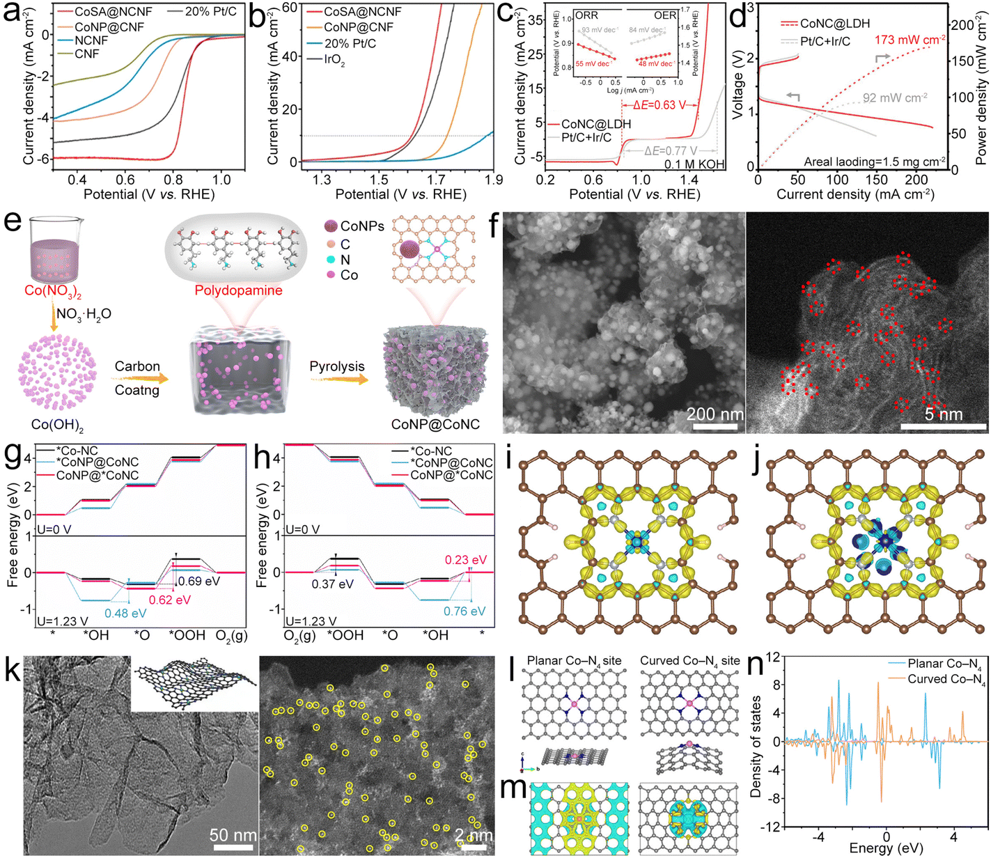 | ||
| Fig. 7 (a) and (b) ORR and OER LSV polarization curves of the as-prepared catalysts. Reproduced with permission from ref. 86. Copyright 2022, American Chemical Society. (c) LSV profiles of the CoNC@LDH and Pt/C + Ir/C electrocatalysts. The inset shows the corresponding Tafel plots for the ORR and OER. (d) Charge and discharge polarization curves and calculated discharge power densities of ZABs with the as-prepared catalysts. Reproduced with permission from ref. 93. Copyright 2021, Wiley-VCH. (e) Diagram of the synthesis of the CoNP@CoNC catalyst. (f) SEM and aberration-corrected (AC) HAADF-STEM (AC-HAADF-STEM) images of the CoNP@CoNC catalyst. (g) and (h) OER and ORR processes of *Co–NC, *CoNP@CoNC and CoNP@*CoNC. (i) and (j) Deformation charge densities of Co–NC and CoNP@CoNC, where the yellow areas and blue areas represent electron accumulation and electron loss, respectively. Reproduced with permission from ref. 94. Copyright 2022, Elsevier. (k) TEM and AC-HAADF-STEM images of CoSA@NG. (l)–(n) Models, calculated differential charge density and DOS of the planar Co–N4 site and the curved Co–N4 site. Yellow and cyan areas represent charge density aggregation and depletion, respectively. Reproduced with permission from ref. 95. Copyright 2022, Springer. | ||
To further enhance the oxygen electrocatalyst performance, atomic-level dispersed Co–N–C and NiFe layered double hydroxide (LDH) composites (CoNC@LDH) were designed.93 Co–N–C and LDH were chosen as ORR and OER active sites. The resultant CoNC@LDH exhibited high bifunctional electrocatalytic activity with a small ΔE of 0.63 V (Fig. 7c) and endowed the ZAB with high PPD (Fig. 7d). Co–N4 and Co NPs can be designed in N-doped carbon (CoNP@CoNC) as a bifunctional oxygen electrocatalyst by polymerization of dopamine hydrochloride and Co(OH)2 followed by a pyrolysis process (Fig. 7e).94 For the OER, Co is the dominating active site in CoNP@CoNC (Fig. 7f) because of the lower overpotential than that of Co–N4 sites (Fig. 7g). While for the ORR, the small overpotential enables the Co–N4 sites to dominate the ORR activity and meanwhile the Co could be beneficial for improving the ORR activity of the Co–N4 site (Fig. 7h). Besides, the Co NPs can optimize the energy barrier of RDS for Co–N4, and the decreased charge accumulation of Co in the Co–N4 site for CoNP@CoNC exhibits efficient electronic regulation of Co toward Co–N4 sites, which could enhance the oxygen catalytic properties (Fig. 7i and j). Due to the existence of Co NPs, more occupied electrons appear near the Ef for the Co d-orbital of Co–N4 sites, which could be removed easily during the electrocatalysis and help to reduce the overpotential of ORR processes. The metallic Co also leads to less occupied d-orbitals for Co of Co–N4 sites in CoNP@CoNC, which contributes to decreased overpotential of OER processes. Owing to the advantages of the coordinated Co–N4 sites and regulated electronic structure of Co–N4 sites by metallic Co, the prepared CoNP@CoNC exhibited a high E1/2 of 0.84 V and a low η10 of 0.29 V, leading to the assembled ZAB with good performance. Indeed, the curvature of the atomic Co–N4–C system would affect its catalytic performance. Wang et al. found that curved Co–N4 exhibits more localized charge densities along with a larger charge gradient than planar Co–N4, which could help to activate O2 (Fig. 7k and l).95,96 The d-band center downshifted for the curved Co–N4 (Fig. 7m), indicating more effective adsorption of oxygenated intermediates than that observed for planar Co–N4, thus optimizing the ORR/OER activity.
 | ||
| Fig. 8 (a) SEM and HAADF-STEM images of NiSA@NC. (b) ORR E1/2 and jk of different catalysts. (c) Mass activity of different catalysts. Reproduced with permission from ref. 97. Copyright 2022, Elsevier. (d) and (e) Optimized structures of TM–N4–G and metal-modified TM–N4–G. (f) and (g) Adsorption energies (Eads) of ORR intermediates and key bond parameters of Fe–N4–G, Co–N4–G, and Ni–N4–G (DO–O: distance between the absorbed oxygen atom and oxygen atom; DM–O: distance between the metal and the nearest oxygen atom; asterisk denotes a catalytic site). Reproduced with permission from ref. 77. Copyright 2020, Elsevier. (h) and (i) DOS and partial charge density of NiO with and without O-deficiencies. (j) Calculated charge density difference of the interface between Ni(111) and Ni-terminated NiO(111), where yellow and blue represent electron accumulation. Reproduced with permission from ref. 100. Copyright 2020, Springer. (k) SEM image of N–NiS1.03HS. (l) and (m) PDOS of NiS1.03 and N-doped NiS1.03. (n) DOS plots of NiS1.03 and N-doped NiS1.03. Reproduced with permission from ref. 102. Copyright 2020, Elsevier. | ||
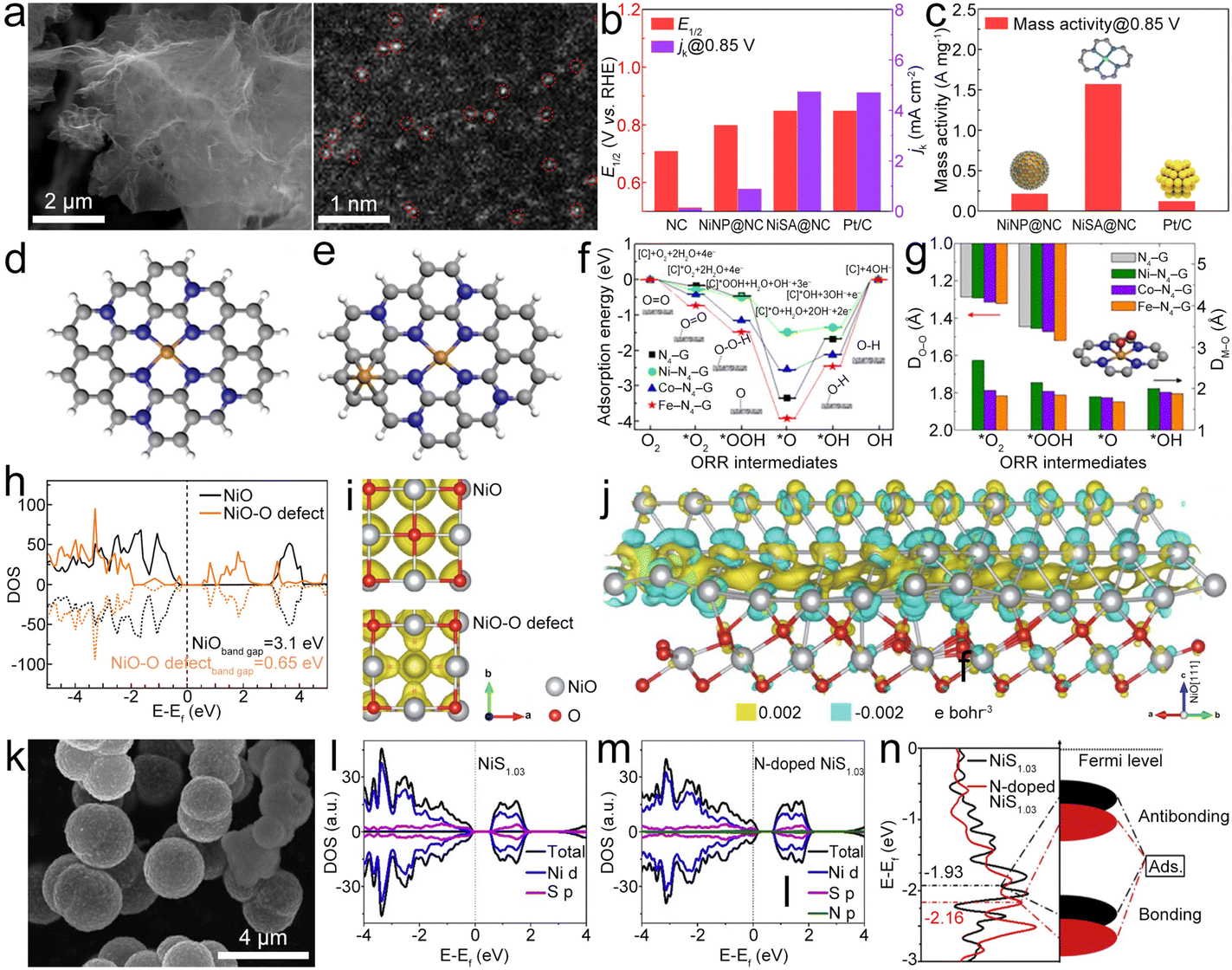
Porous Ni/NiO nanosheets can be synthesized as bifunctional electrocatalysts for ZABs.100 The introduction of oxygen deficiencies leads to a narrowing of the band gap in NiO to 0.65 eV (Fig. 8h), which is instrumental in enhancing the conductivity (Fig. 8i) of the Ni/NiO system, thereby facilitating expedited charge transfer during the catalytic process. The charge density difference of the interface between Ni(111) and NiO(111) with terminal Ni (Fig. 8j) shows that the electrons would accumulate at the interface and then transfer from NiO to Ni, thus improving the electronic conductivity of Ni/NiO and exhibiting outstanding bifunctional electrocatalytic activities. Yan et al. developed a 3D CNT/rGO heterostructure film (CGHF) with a large surface area, controllable dopants, hierarchical pores, and a highly conductive CNT@rGO heterostructure.101 The encapsulation of the Ni NP core in the N-doped carbon shell (NiNP@NC) leads to synergistic effects with adjusted electronic structure and optimized free energy for electrochemical reactions, which results in low free energy for H adsorption and low energy barrier for OER and ORR pathways. Zhang et al. engineered N-doped NiS1.03 hollow spheres (N–NiS1.03HS) (Fig. 8k) as a bifunctional catalyst.102 After N doping, NiS1.03 displays metallic nature (Fig. 8l and m), enabling efficient charge transfer in the catalytic process. The calculated energy for the d-band center of NiS1.03 downshifts after N-doping (Fig. 8n). This leads to more electrons occupying the anti-bonding orbital and facilitating the adsorption/desorption of oxygen-containing intermediates in N–NiS1.03, which can decrease the overpotential of the RDS, thus enhancing OER/ORR reaction kinetics.103–105 Finally, the N–NiS1.03HS-based ZAB showed a high OCV of 1.41 V and a capacity of 821 mA h g−1. This study would guide the N doping for designing advanced bifunctional catalysts based on metal sulfides. Similar N–CoSe2 active sites can be identified in the CoSe2 NPs and porous N-doped carbon catalyst (CoSe2@NC).106
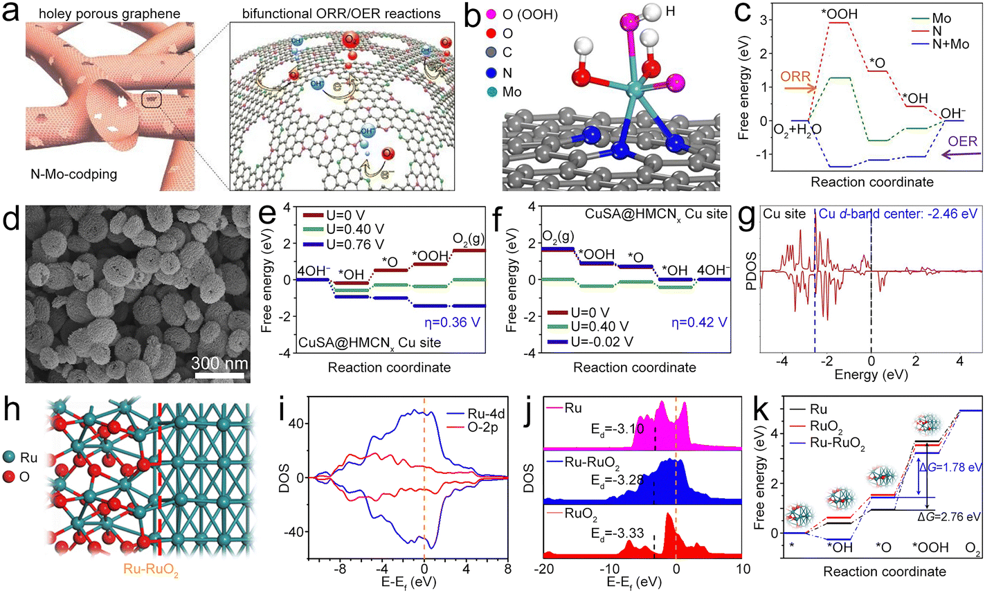 | ||
| Fig. 9 (a) Diagram of Mo@NG. (b) Atomic configuration of the *OOH intermediate on Mo@NG. (c) Free energy diagrams of the ORR and OER processes. Reproduced with permission from ref. 1. Copyright 2020, Elsevier. (d) SEM image of CuSA@HNCNx. (e) and (f) Free energy diagrams of the OER and ORR for the CuSA@HNCNx catalyst. (g) PDOS of Cu in CuSA@HNCNx. The blue and black dashed lines represent the d-band center of Cu and the Ef. Reproduced with permission from ref. 108. Copyright 2020, Elsevier. (h) Diagram of the atomic structure of the Ru–RuO2 hetero-interface. (i) DOS of the Ru–RuO2 heterojunction. (j) DOS and d-band of RuO2 and Ru–RuO2. (k) Free energy diagrams of Ru, RuO2 and Ru–RuO2 for the OER. Reproduced with permission from ref. 109. Copyright 2022, Elsevier. | ||
Overall, a series of single metal component bifunctional catalysts are used to construct high performance ZABs. It should be noted that most of the reported catalysts are based on Fe, Co and Ni. These catalysts are constructed primarily as single atom M–N (M = Fe, Co, Ni) active sites supported on a carbonaceous framework. Due to the high activity and large specific surface area of single atoms, M–N catalysts tend to exhibit good bifunctional catalytic activity to promote the ORR/OER. During the ORR, these single atom catalysts exhibit a similar redox couple between M(II) and M(III) states. The formed surface oxides and hydroxides for Fe–N/Ni–N catalysts and surface Co-oxo species for the Co–N catalyst during the ORR contribute to the catalytic activity by adsorbing oxygen and facilitating the ORR. During the OER, Fe–N catalysts can form active Fe(IV) oxide species and Co–N catalysts typically transition between Co(III) and Co(IV) oxidation states to form Co(IV) oxo species, which play a crucial role in the oxidation of water to produce oxygen. While Ni is less commonly used for the OER due to the tendency to form less active Ni(III) species, certain Ni-based catalysts may involve the oxidation state of Ni(III) in the OER mechanism. Surface modifications are often employed to enhance OER activity. According to the literature, the intrinsic ORR activity follows the order of Fe > Co > Ni, while the OER activity follows the trend Ni > Co > Fe. These differences are strongly dependent on their d-orbital configurations, coordination environments, and redox properties.44,111,112
3.2. Multiple metal components
The FeCo alloy (FeCoAL) (Fig. 10a) can be prepared as a bifunctional catalyst for the ZAB.113 Co(111) catalyzes the ORR by a dissociative mechanism, but it is prevented by *OH desorption owing to the positive Gibbs free energy (ΔG) (Fig. 10b). In contrast, Fe(111) prefers to induce the ORR by the *OOH mechanism, and the *OH can be desorbed on Fe(111) easily. When Fe and Co are alloyed, the synergetic merits as the ORR catalyst can be realized simultaneously in the CoFe alloy, and it tends to catalyze the ORR via a dissociative mechanism, which has enhanced kinetics compared to the *OOH mechanism. The increased ORR activity of the FeCo alloy catalyst is mainly attributed to the Fe atom inducing electron redistribution, thus leading to a lower overpotential than that of the single component Co(111) or Fe(111) catalyst. Considering the advantages of the alloy, plentiful studies have been performed based on the FeCo alloy and different carbon materials, which show good ORR and OER properties. These studies provide important references for the application of FeCo alloy based bifunctional catalysts in ZABs. Pei et al. created a bamboo-structured electrocatalyst of the FeCo alloy embedded in the carbon nanofiber (FeCoAL@CNF) (Fig. 10c).114 When combined with a highly conductive hydrogel electrolyte, the assembled ZAB could demonstrate high capacity and energy density retention at low working temperature. The FeCo alloy was incorporated into the NCNTs (FeCoAL@NCNT) as the catalyst.115 The optimized FeCoAL@NCNT (Fig. 10d) catalyst shows high bifunctional electrocatalytic activities with an E1/2 of 0.87 V and an η10 of 0.276 V. Tang et al. designed FeCo2 alloy NPs with the size of 15 ± 5 nm embedded in N-doped carbon (FeCo2AL@NC) (Fig. 10e and f), which has high-density active sites, as an electrocatalyst for the ZAB.116 The graphitic carbon shells could protect metallic cores from being corroded and oxidized, and the overall carbon network anchors this FeCo2@NC composite unit with well-controlled uniform dispersion.
 | ||
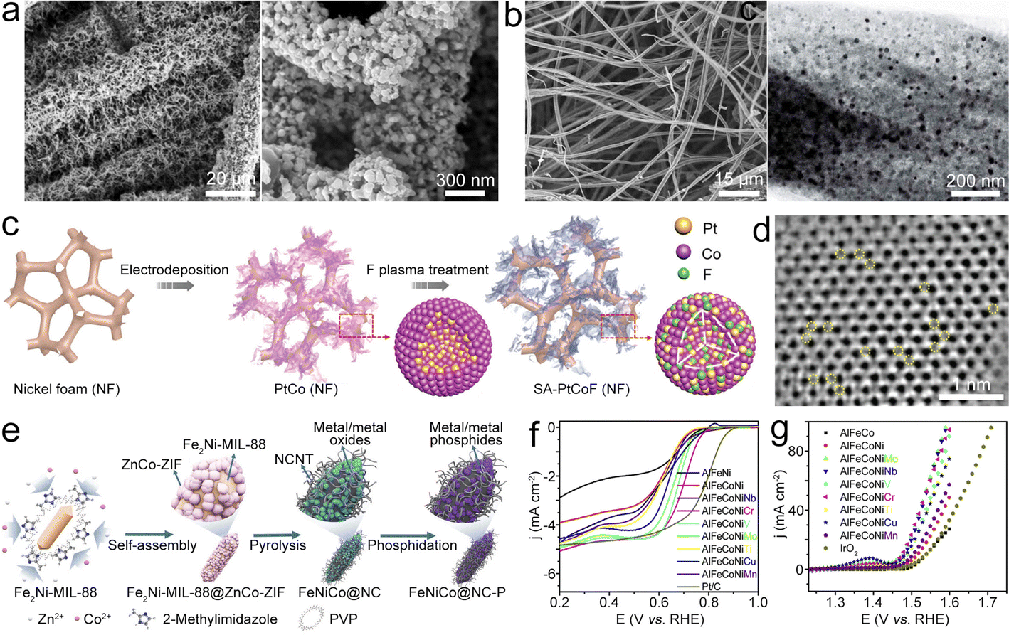
| Fig. 10 (a) STEM and HRTEM images of the FeCoAL catalyst. (b) Electron localization function patterns of Co(111), Fe(111), and FeCoAL(111), and the corresponding ΔG of adsorption for O2/OH− on them. Reproduced with permission from ref. 113. Copyright 2022, American Chemical Society. (c) Digital photo of bamboo and SEM image of polymer fibers. Reproduced with permission from ref. 114. Copyright 2020, Wiley-VCH. (d) TEM images of CoFe@NCNT/CFC. Reproduced with permission from ref. 115. Copyright 2020, Royal Society of Chemistry. (e) Diagram of the synthesis of FeCo2@NCS. (f) TEM image of FeCo2@NC. Reproduced with permission from ref. 116. Copyright 2020, American Chemical Society. (g) Free energy diagrams of the OER on Co@NC and FeCo@NC. (h) Charge density difference of the FeCo(110) layer and NC(111) layer (the yellow and blue isosurfaces show the electron gain and loss, respectively). Reproduced with permission from ref. 117 (https://mailto:117). Copyright 2021, Springer. (i) SEM image of ZnCoFe-ZIF. (j) DOS of Co5.47N/Fe3Co7@NC. Reproduced with permission from ref. 122. Copyright 2022, Wiley-VCH. | ||
Heterostructured Co/FeCo NPs can be incorporated into N-doped carbon (Co/FeCo@NC) as the catalyst for the ZAB.117 Co@NC and FeCo@NC catalysts both display uphill pathways (Fig. 10g). While the RDS of Co@NC (*OOH formation) has a high overpotential of 2.06 V, FeCo@NC shows a low OER overpotential of 1.77 V, which can be attributed to the fact the introduction of the Fe atom could modulate the binding strength of OER intermediates.118,119 Furthermore, in this design, electrons are transferred from FeCo to the NC layer, resulting in the creation of an electron-rich state on the NC layer (Fig. 10h). This induces additional surface catalysis on the carbon matrix, consequently enhancing the high oxygen electrocatalytic activity of Co/FeCo@NC. FeCo alloy NPs were also designed in N, S co-doped carbon (FeCoAL@NSC) as a catalyst for the ORR/OER.120 FeCo can be fixed to NSC through metal–heteroatom–carbon bonds, which results in good bifunctional catalytic performances, leading to a high-performance ZAB with a high PPD and specific capacity. Shi et al. anchored the FeCo alloy and Co2P NPs on N, P co-doped (FeCo/Co2P@NPCNF) as a ZAB catalyst.121 The synergistic effects of Co2P and FeCo alloys endow the FeCo/Co2P@NPCNF catalyst with high ORR and OER activities. Electrochemical test results show that the bifunctional activity parameter of ΔE is down to 0.77 V. The improved ORR activity, namely a more positive onset and a low E1/2 and Tafel slope, is mainly enabled by the FeCo NPs. For the OER, the synergistic effects of Co2P and FeCo play a major role in significantly enhancing activity with low overpotential.
By using a tri-metal ZIF (Fig. 10i) as a precursor, Fe3Co7 and Co5.47N (CoFeN) can be embedded in the NCNT-modified 3D cruciform carbon matrix (FeCoN@NCNT) as an electrocatalyst for the ZAB.122 In this design, Co5.47N/Fe3Co7@NC has a middle d-band center with the value between Fe/Fe3C@NC and Co@NC (Fig. 10j), which shows an appropriate adsorption strength conducive to the ORR/OER. The robust interfacial conjugation of Co5.47N/Fe3Co7 along with the hierarchical structure can generate more active sites and create a large surface area, leading to FeCoN@NCNT exhibiting high bifunctional catalytic activities and stability. Moreover, Se-doped CNTs were also reported as the supports for the FeCo alloy (FeCoAL@SeCNT), promising enhanced conductivity and increased active sites. This configuration exhibits commendable ORR and OER performance, along with superior durability.123
FeNi alloy NPs can be incorporated in NCNTs (FeNiAL@NCNT), and the embedded FeNi can enhance the adsorption capabilities of OH− and oxygen, which is beneficial for the OER/ORR.124 In this composite, the bond formed between the FeNi alloy and NCNTs can promote the ORR/OER process. As an electrocatalyst, FeNiAL@NCNT exhibited an E1/2 of 0.75 V and a low η10 of 0.29 V. Lai et al. embedded the FeNi alloy in NCNFs and carbon cloth (FeNiAL@NCNF/CC) (Fig. 11a).119 The elongated and interlaced NCNF constructs a 3D conductive network, enabling 3D spatial distribution of FeNi NPs, which could increase the electrochemical active area and promise sufficient active sites, resulting in superior bifunctional catalytic performance. The FeNi alloy can be loaded on bamboo stick-derived carbon fibers with N doping (FeNiAL@NCF) as a bifunctional oxygen electrocatalyst for the ZAB (Fig. 11b).125 The NCF possesses high surface area with abundant active sites, which can promote mass transport during the electrochemical reactions. Besides, doping N could alter the charge distribution of neighboring C atoms and proliferating Lewis base sites to enhance oxygen redox catalysis. The synergistic effects between FeNi NPs and NC also help to promote catalytic performance. Similar works were also reported by encapsulating the FeNi3 alloy in NC (FeNi3AL@NC)126 and dispersing the FeNi alloy in N-doped layered carbon nanosheets (FeNiAL@NLCN) as ORR/OER catalysts for ZABs.127
 | ||
| Fig. 11 (a) SEM images of FeNiAL@NCNF/CC. Reproduced with permission from ref. 119. Copyright 2021, Elsevier. (b) SEM and TEM images of FeNiAL@NCF. Reproduced with permission from ref. 125. Copyright 2020, Royal Society of Chemistry. (c) Diagram of the synthesis for SA-PtCoF. (d) STEM image of SA-PtCoF. Reproduced with permission from ref. 130. Copyright 2020, Royal Society of Chemistry. (e) Diagram of the synthesis of FeNiCoP@NC. Reproduced with permission from ref. 133. (f) and (g) ORR and OER polarization curves of different catalysts. Reproduced with permission from ref. 134. Copyright 2020, Elsevier. | ||
In addition to FeNi alloys, CoNi alloys can also be introduced in NCNT arrays (CoNiAL@NCNT) as catalysts for ZABs, which have the optimized adsorption energy and abundant Co–Nx, Ni–Nx active sites.128 The interconnected 3D network could inhibit the aggregation and delamination of internal CoNi NPs, accelerate electron transfer, and enable efficient reactant transport and electrolyte penetration, leading to enhanced bifunctional catalytic activity. Based on the CoNiAL@NCNT catalyst, the ZAB in both the liquid-state and all-solid-state exhibited low charge/discharge ΔV and good cycling stability. Sheng et al. synthesized the CoNi alloy on N-doped hollow carbon spheres (NCS)/tubular carbon (TC) composites (CoNiAL@NCS/TC) as the catalyst for the ZAB.129 The prepared catalyst exhibit good bifunctional catalytic activity, which is mainly owing to the synergistic effects of plentiful Co–Ni/N coordinations, large surface area with abundant exposed active sites, and efficient gas diffusion and mass transport induced by the porous nanostructures. These studies manifest that FeNi alloys have excellent catalytic properties for the ORR and OER.
Combining electrodeposition and F-plasma etching treatment, the PtCo alloy can be synthesized (Fig. 11c and d).130 In this design, F atoms could induce lattice distortion in PtCoF, thereby enhancing the utilization efficiency of Pt. Additionally, the PtCoF catalyst optimizes the charge and spin densities of atoms, resulting in improved electron transfer and significantly enhanced catalytic activity.131,132 Due to the synergistic effects, the bifunctional PtCoF catalyst exhibits a better activity and durability, resulting in the ZAB with high electrochemical performances. This research offers a good reference for applying alloy-stabilized atomic catalysts as electrocatalysts for the ZAB. Ren et al. designed a dual-MOF pyrolysis strategy (Fig. 11e) utilizing the Fe2Ni-MIL-88@ZnCo-ZIF precursor to fabricate Fe–Ni–Co metal/metal phosphide NPs embedded in the CNT-grafted and N-doped carbon matrix (FeNiCoP@NC).133 The hybrid material features the embedded FeNiCoP NPs, N-doping, and porous structure along with high surface area, thus showing an E1/2 of 0.84 V for the ORR and an η10 of 0.31 V for the OER. To achieve the possible bifunctional catalytic activities without noble metal elements, Fang et al. prepared the AlFeCoNiCr combined catalyst for the ZAB.134 Incorporation of Cr could modify the electronic structure of the surface oxides, which is conducive to the increased ORR/OER activities (Fig. 11f and g). Consequently, the AlFeCoNiCr catalyst based all-solid-state ZAB achieved a small ΔV of 0.76 V and superior cycling durability. This study offers a good reference for developing multifunctional catalysts via increasing the complexity of alloys/oxides.
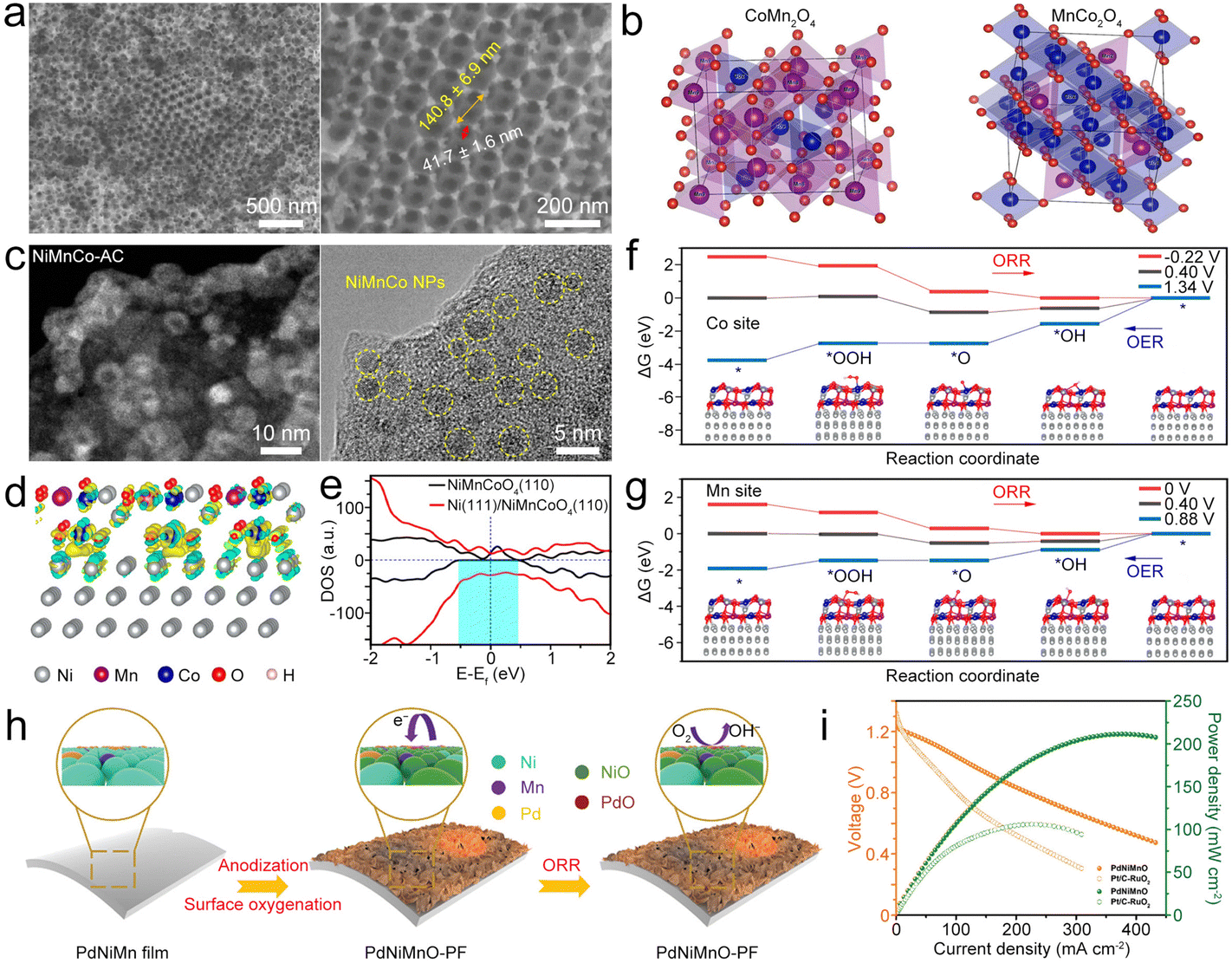 | ||
| Fig. 12 (a) SEM images of CoMn2O4/3DOM. (b) Primitive cells for Co0.75Mn2.25O4 and Mn0.75Co2.25O4/3DOM spinels. Reproduced with permission from ref. 148. Copyright 2020, American Chemical Society. (c) STEM and HRTEM images of the NiMnCo-AC catalyst. (d) Interfacial electron transfer in Ni(111)@NiMnCoO4(110). Yellow and cyan iso-surfaces represents electron accumulation and electron depletion. (e) DOS on NiMnCoO4(110) and Ni(111)@NiMnCoO4(110). (f) and (g) ΔG diagrams of the ORR/OER on the Co sites and Mn sites of Ni(111)@NiMnCoO4(110). Reproduced with permission from ref. 150. Copyright 2022, National Academy of Science. (h) Diagram of surface oxygenation and the working principle of the PdNiMnO-PF catalyst during the ORR. (i) Comparison of polarization and power density curves of PdNiMnO and Pt/C–RuO2. Reproduced with permission from ref. 151. Copyright 2022, Royal Society of Chemistry. | ||
Jiao et al. synthesized NiMnCo-activated carbon (NiMnCo@AC) catalysts (Fig. 12c) from used NiMnCo cathodes.150 The NiMnCo NPs show core–shell structures with the Ni core and the NiMnCoO4 shell. After coupling NiMnCoO4(110) with Ni(111) (Fig. 12d), apparent electron transfer from Ni to NiMnCoO4 occurred, generating an electron-rich region in the NiMnCoO4 layer. The Ni core could induce the redistribution of electronic structure in NiMnCoO4, leading to enhanced electron mobility (Fig. 12e), thus improving the electrocatalytic performance. Importantly, O2 prefers to bind with Mn and Co atoms on the surface of Ni@NiMnCoO4, and the ΔG values of both O2 and OH− become lower, enabling the bifunctional catalysis of Ni@NiMnCoO4. In this catalyst, the Mn site is the leading active site for Ni@NiMnCoO4, because it has reduced overpotentials for the ORR and OER compared to those of Co sites (Fig. 12f and g). As a result, the designed ZAB with the NiMnCo@AC cathode exhibited a high discharge capacity, low ΔV, superior cycling stability, and good flexibility to power the LED at a bending state. Zhang et al. electrodeposited PdNiMn as a precursor to form an oxygenated PdNiMnO porous film (PdNiMnO-PF).151 Similar to NiMnCo, the enhanced interaction between Pd and NiMnO-PF could boost ORR activity because of the promoted charge transfer at the Pd/NiMnO interfaces. Besides, the formed oxygenated phase around Pd active sites could act as a secondary adsorption site for reducing the reaction energy barrier (Fig. 12h).152,153 In addition, NiMnO has high OER activity, enabling PdNiMnO-PF to be used as a bifunctional ORR/OER electrocatalyst for the ZAB154 and resulting in the high-performance ZAB with the PdNiMnO-PF catalyst showing a PPD of 211.6 mW cm−2 (Fig. 12i) and long cycling stability for 2000 h.
A bifunctional Mn-doped RuO2 (Mn–RuO2) (Fig. 13a) catalyst was constructed by Zhang's group, which demonstrates the atomic dispersion of Mn in the RuO2 lattice.155 In this catalyst, Ru sites on Mn–RuO2 enable high OER activity similar to RuO2, and Mn sites show high ORR activity better than the MnO2 catalyst (Fig. 13b and c). Interestingly, Mn and Ru sites on the surface of Mn–RuO2 are simultaneously in lower oxidation states as compared to MnO2 and RuO2 (Fig. 13d), and Mn–O bonds in Mn–RuO2 can be elongated. The local tensile strain on the Mn sites results in decreased electronic hybridization between Mn 3d and O 2p, leading to a sharper Mn 3d peak shifting toward Ef (Fig. 13e),156 corresponding to an optimized binding energy of *OH,157 thus showing enhanced ORR activity. In addition, the local chemical environment of Mn–RuO2 can tune the electronic configuration of Mn sites and regulate the binding energy, resulting in optimum ORR activity. The resultant Mn–RuO2 catalyst exhibited enhanced bifunctional activities (Fig. 13f and g), enabling the ZAB to deliver high PPD, low ΔV, and superior durability. This work offers profound insights into adjustment of atomic and electronic configurations to enhance the oxygen activity of Ru-based bifunctional catalysts. RuCoOx bimetallic oxides constructed by this group also show good trifunctional ORR/OER catalytic activities with a narrow ΔE of 0.65 V bestowing the ZAB with a large PPD of 160 mW cm−2.158 S-doping can narrow the band gap of bimetallic LaCoO3 (Fig. 13h and i), and introducing oxygen defects in S-doped LaCoO3 (S-LCO) (Fig. 13j) would lead to more electron-occupied states at the Ef, thus speeding up charge transfer, which is beneficial for electrocatalysis.159 The S-LCO with oxygen defects has low energy barrier for the RDS (*OOH formation) (Fig. 13k), and S-doping could be the main reason for enhancing the catalysis of adjacent Co sites. Therefore, the designed LCO with 5.84% S-doped showed enhanced bifunctional electrocatalytic activities, leading to high PPD and long-term cycle life when used as the ZAB catalyst.
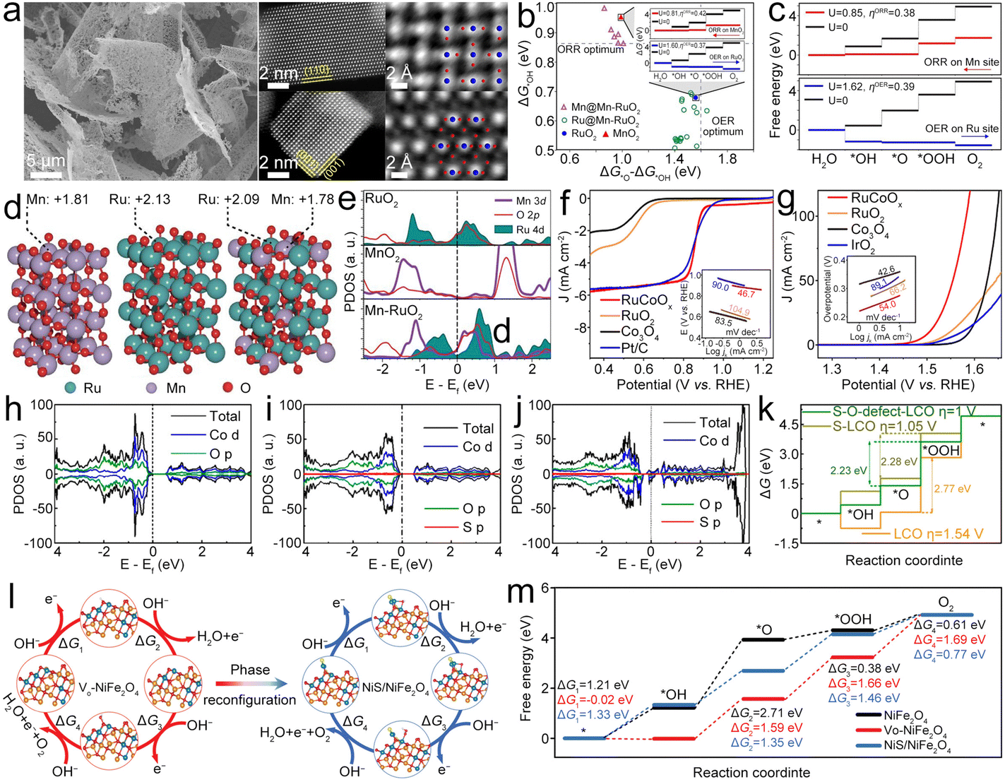 | ||
| Fig. 13 (a) SEM and STEM images of Mn–RuO2. (b) OER and ORR activities with ΔG*OH and ΔG*O − ΔG*OH as the descriptors. (c) ΔG diagrams of the most active sites for the ORR and OER. (d) Oxidation states of surface Mn and Ru for MnO2, RuO2, and Mn–RuO2 based on Bader charge analysis. (e) PDOS of different catalysts. Reproduced with permission from ref. 155. Copyright 2022, American Chemical Society. (f) and (g) ORR and OER LSV curves and corresponding Tafel plots for different catalysts. Reproduced with permission from ref. 158. Copyright 2021, American Chemical Society. (h)–(j) DOS of S-LCO with an O defect and their control samples. (k) ΔG changes of S-LCO with an O defect and their control samples during the OER. Reproduced with permission from ref. 159. Copyright 2020, American Chemical Society. (l) OER reactions on Vo-NiFe2O4 and NiS/NiFe2O4 configurations. (m) ΔG diagrams of the OER on different catalysts. Reproduced with permission from ref. 161. Copyright 2022, Wiley-VCH. | ||
Zhao et al. synthesized a composite electrocatalyst consisting of Co coordinated framework porphyrin-coated CNTs and NiFe LDH (LDH-POF), which affords efficient ORR/OER active sites at the microscale and mesoscale to promote ion transport.160 The LDH-POF catalyst showed a lower ΔE of 0.68 V and lower ORR Tafel slope than the Pt/C + Ir/C catalyst, as well as similar OER Tafel slopes to Pt/C + Ir/C, resulting in the constructed ZAB with a high PPD of 185.0 mW cm−2 and long cycling life of 2400 cycles at 5.0 mA cm−2. Shao et al. fabricated spinel oxide of the NiS/NiFe2O4 composite by using energetic Ar plasma-induced phase reconfiguration inside the defective S-doped NiFe2O4.161 In this design, the plasma destroys the long-range order of NiFe2O4 leading to the formation of the short-range NiS domain along with intrinsic defects. On the basis of four proton-coupled reaction steps (Fig. 13l), the RDS for NiS/NiFe2O4 (*OOH formation) requires a low ΔG, and therefore, the phase reconfiguration arising from the Ni–S coordination can facilitate the OER (Fig. 13m), leading to the NiS/NiFe2O4 catalyst exhibiting a low OER overpotential and high ORR E1/2. As a bifunctional catalyst for the ZAB, the NiS/NiFe2O4 catalyst can realize a PPD of 148.5 mW cm−2. This research offers an effective strategy to synthesize a superior catalyst by in situ phase reconfiguration.
Fe and Co dual species can be atomically dispersed with Fe–N3 and Co–N3 coordination (FeCoN6) in CNFs (Fe–Co@CNF) as the catalyst for ZABs (Fig. 14a and b).162 In this configuration, an increased charge transfer from CNFs to FeCoN6 species augments their ORR/OER activity (Fig. 14c). Within this framework, the Fe site predominantly contributes to the ORR, whereas the Co site demonstrates optimal OER activity, as evidenced by the ΔG curves (Fig. 14d). Therefore, Fe–Co@CNF with highly active FeN3–CoN3 sites showed an E1/2 of 0.87 V for the ORR to OH− and an η10 of 0.5 V for the OER, leading to the ZAB delivering a PPD of 201.7 mW cm−2 and good cycling stability. Chen et al. synthesized Fe and Co bimetallic sites atomically dispersed into N-doped carbon aerogels (Fe–Co@NCAG).163 In this catalyst, the FeN3 and CoN3 coordinations are on mutually orthogonal planes (Fig. 14e) with Fe–Co bonding linkage and a tilted N–Co bond. The synergistic effects of bimetal sites could decrease the free energy of RDS in the ORR/OER, resulting in promoted catalytic activity with a narrow ΔE of 0.64 V (Fig. 14f).164–166 When applied as the oxygen catalyst for the air cathode, the Fe–Co@NCAG based ZAB performed well with both liquid and solid electrolytes. Likewise, Fe and Co atoms were incorporated into N, S co-doped hollow carbon spheres (Fe–Co@NSCS) to pursue boosted catalytic activity.167
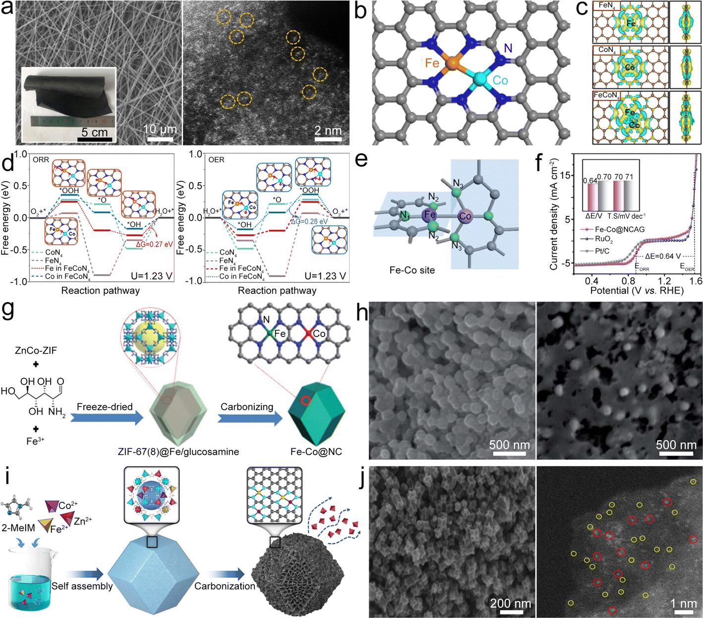 | ||
| Fig. 14 (a) SEM and STEM images of Fe–Co@CNF. (b) Proposed structure of the Fe–Co–N6 site in Fe–Co@CNF. (c) Charge density difference between dopants and the graphitic carbon layer. (d) ΔG diagrams of the ORR and OER on Fe–N4, Co–N4, and Fe–Co–N6 sites. Reproduced with permission from ref. 162. Copyright 2020, Elsevier. (e) Diagram of the structure of the Fe–Co dual metal sites in Fe–Co@NCAG. (f) Combined polarization curves of oxygen electrocatalysis of Fe–Co@NCAG and Pt/C–RuO2. Reproduced with permission from ref. 163. Copyright 2020, Royal Society of Chemistry. (g) SEM image of ZnCo-ZIF@Fe/glucosamine and Fe–Co@NC. (h) Diagram of the synthesis of Fe–Co@NC. Reproduced with permission from ref. 169. Copyright 2020, Royal Society of Chemistry. (i) Diagram of the synthesis of the Fe–Co@NC catalyst. (j) SEM and STEM images of Fe–Co@NC (red circles indicate diatoms and yellow circles indicate single atoms). Reproduced with permission.172 Copyright 2022, American Chemical Society. | ||
ZIFs are often used as precursors to prepare bimetallic atom site catalysts for building high-performance ZABs. For example, atomically dispersed Fe and Co sites in N-doped carbon nanospheres (Fe–Co@NCS) can be designed through annealing treatments and acid washing of ZIF-8 on carboxylic polystyrene nanospheres.168 Due to abundant atomic-level active sites and the synergetic effect of bimetallic sites, Fe–Co@NCS can show good oxygen electrocatalysis with a high ORR onset potential and E1/2. For the OER, Fe–Co@NCS attained an η10 of 0.36 V. Benefiting from the bifunctional activity, the ZAB with the Fe–Co@NCS based air cathode exhibited a stable OCV of 1.43 V along with good cycling stability. By carbonizing ZIF-8/67 encapsulated with Fe3+ and glucosamine, Fe–Co@NC bifunctional electrocatalysts can be synthesized (Fig. 14g and h).169 A small ΔE of 0.71 V can be achieved for this Fe–Co@NC catalyst, suggesting its good bifunctional catalytic activities,170,171 which are mainly arising from the synergetic effects of Fe and Co sites decreasing the ΔG of adsorbed intermediates. Applied as an air electrode, the Fe–Co@NC driven all-solid-state ZAB could exhibit superior PPD and cycling stability. Similarly, a catalyst based on Fe and Co coordinated with N and incorporated into a carbon matrix (Fe–Co@NC) derived from ZIF-8 (Fig. 14i and j) was reported by He et al.172 By optimizing the Fe/Co ratio and pyrolysis temperature, the Fe–Co@NC bifunctional electrocatalyst with FeCo–N6 sites shows better catalytic activity than single-metal site based Fe@NC and Co@NC catalysts, resulting in the ZAB with a high PPD of 372 mW cm−2 and good cycling stability. This work has laid a good foundation for the design of multiple M–N–C catalysts.
Apart from Fe, Co bimetallic atom sites, Fe, Mn-based bimetallic atom sites were widely reported to construct high-activity electrocatalysts. Cui et al. designed an Fe and Mn bimetallic atom site catalyst loaded on N-doped carbon nanosheets (Fe–Mn@NC) by a pyrolysis strategy (Fig. 15a and b).173 In this catalyst, the Fe and Mn coexist in the form of FeMnN6 structure, and the adjacent connection of these two atomic sites enables a unique adsorption configuration for *OOH, leading to a lower *OOH dissociation energy barrier (0.1 eV). Therefore, Fe–Mn@NC could accelerate the ORR process and display a narrow ΔE of 0.71 V. In addition, Fe and Ni bimetallic atom sites on defect-rich porous carbon with N, S co-doped (Fe–Ni@DNSC) can be synthesized as a bifunctional electrocatalyst.174 The S dopant and C vacancies could optimize the d-band center of Fe and Ni and weaken the binding strength between OH− and the Fe site, promoting the desorption of *OH and thereby enhancing the ORR/OER performance. Due to the synergetic effects of Fe and Ni bimetallic atom sites, the ZAB with the Fe–Ni@DNSC catalyst delivered a PPD of 160 mW cm−2 and high discharge capacity. A similar work on Fe, Ni bimetallic atom sites on the carbon with N doping (Fe–Ni@NC) was also reported by Luo et al.,175 where the Fe,Ni bimetallic atom sites show a low ΔG (Fig. 15c and d), therefore promising a good oxygen electrocatalysis.
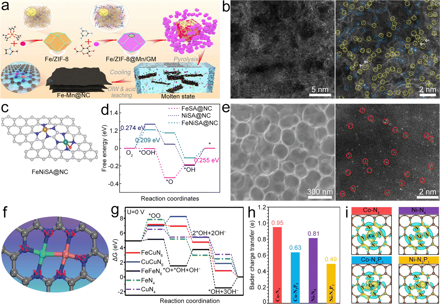 | ||
| Fig. 15 (a) Diagram of the synthesis of Fe–Mn@NC. (b) STEM images of Fe–Mn@NC. Reproduced with permission from ref. 173. Copyright 2022, Wiley-VCH. (c) Structures of different catalysts. (d) ΔG diagrams of the ORR on different catalysts. Reproduced with permission from ref. 175. Copyright 2021, Elsevier. (e) SEM and STEM images of the Fe–Cu@NHC catalyst. (f) Proposed architecture of Fe–Cu dual sites. The gray, blue, green, and orange spheres represent the C, N, Fe, and Cu atoms, respectively. (g) ΔG diagram for the ORR on different models. Reproduced with permission from ref. 176. Copyright 2021, Wiley-VCH. (h) and (i) The top views of charge density differences and Bader charge transfers of middle metallic element on the surfaces of different catalysts. Reproduced with permission from ref. 177. Copyright 2021, Springer. | ||
To achieve the high activity for the ORR, Sun et al. demonstrated bimetallic atom sites of Fe–N6 and Cu–N6 (FeCuN6) composite catalysts (Fe–Cu@NHC) to boost oxygen dissociation for the ZAB (Fig. 15e and f).176 The optimal formation energy of *OO adsorbed on the FeCuN6 structure (Ef = −1.552 eV) is neither too weak for oxygen absorption nor too strong for ORR product desorption. Once the O2 is absorbed on the FeCu site, the O–O bond will be elongated, which is beneficial for its following dissociation. Density functional theory (DFT) results show a low reaction energy (2.205 eV) of FeCuN6 at the RDS (O2 adsorption) (Fig. 15g), illustrating its good catalytic activity. As expected, the Fe–Cu@NHC catalyst delivered a higher E1/2 of 0.92 V than the catalysts with the sole-metal site. The Co, Ni bimetallic atom site catalyst can be synthesized by using a P–doped metal organic framework (MOF) as a support.177 The obtained Co–Ni@PNC catalyst with Co–PNC and Ni–PNC has a more robust electronic localization than Co–NC and Ni–NC, resulting in a bigger charge accumulation (Fig. 15h). At the same time, the charge numbers of Co and Ni reduce after P doping according to the Bader charge density differences (Fig. 15i). In addition, the antibonding states of the M–N3P1 configuration and adsorbed species are less occupied, thereby optimizing the binding strength of oxygen-containing intermediates so as to guarantee superior OER/ORR activities. Therefore, the Co–Ni@PNC based ZAB exhibited a PPD of 252 mW cm−2 and a high OCV of 1.59 V.
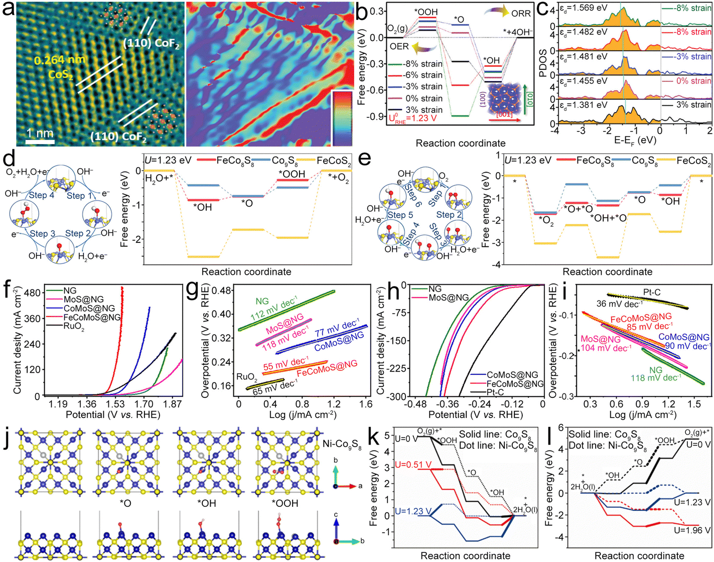 | ||
| Fig. 16 (a) HAADF-STEM image and the corresponding geometric phase analysis for the lattice strain distribution at the CoF2–CoS2 interface. (b) ORR/OER ΔG diagrams under different strains. (c) PDOS of the d-band of Co atoms in the CoS2(100) facet under different strains. Reproduced with permission from ref. 178. Copyright 2021, Royal Society of Chemistry. (d) and (e) OER and ORR pathways on the surface of FeCo8S8, and the corresponding calculated free energy profiles on the active centers of different catalysts. Reproduced with permission from ref. 180. Copyright 2020, American Chemical Society. (f)–(i) LSV curves and Tafel plots of different materials for the OER and HER. Reproduced with permission from ref. 181. Copyright 2020, Elsevier. (j) The models of pristine and stable adsorption configurations of OER/ORR intermediates of Ni–Co9S8. (k) and (l) ΔG diagram of Co9S8 and Ni–Co9S8 at different operation potentials for the ORR and OER. Reproduced with permission from ref. 185. Copyright 2021, Elsevier. | ||
Lu et al. developed FeCo dual-metallic sulfides on rGO (FeCo8S8@rGO).180 For the OER, FeCo8S8@rGO presents an appropriate adsorption energy for reactants leading to the RDS (*OOH formation) on FeCo8S8 and shows a lower ΔG than Co9S8 and FeCoS2 (O2 generation) and improved OER activity (Fig. 16d). For the ORR (Fig. 16e), FeCo8S8 shows a lower energy barrier to dissociate the O–O bond than Co9S8 and FeCoS2. Thus, enhanced OER/ORR catalytic activities can be realized by optimizing Fe/Co composition, leading to a low ΔE of 0.77 V and low ΔV. This work indicates that the appropriate Fe contents could reduce the activation energy for OH− oxidation to O2 and retain the activation energy of O2 reduction to OH−. Ramakrishnan et al. reported an N-doped graphene (NG) encapsulated FeCoMoS (FeCoMoS@NG) core–shell composite,181 which features a large surface area, abundant porous networks, and synergistic interaction between the FeCoMoS core and NG shell.182–184 Thus superior OER and ORR activities (Fig. 16f–i) can be achieved. Ni-doped Co9S8 can be composited with reduced-graphene-nanoribbons (Ni–Co9S8@rGN) to improve the ORR/OER activities.185 Ni doping in Co9S8 could regulate the adsorption for oxygen species and enhance the activities by decreasing ΔG at the RDS (Fig. 16j–l), thus improving the ORR/OER activities of Ni–Co9S8/rGN. As a bifunctional catalyst for the ZAB, higher PPD, superior rate and cycling performances can be realized. This work provides novel insights for development of low-cost and high-efficiency bifunctional oxygen catalysts. Moreover, MoC and Mo2C are also composited with Co NPs as highly efficient bifunctional catalysts.186,187
Hou et al. found that Ru competitive coordination can induce local lattice strain of ZnIn2S4 (Ru0.1ZIS) and therefore Ru0.1ZIS can be used as a catalyst for ZABs.188 Introducing Ru could cause local lattice strain for developing highly efficient catalysts (Fig. 17a). In addition, 3D flower-like R0.1ZIS could facilitate charge transfer via regulating the d-band center of active sites away from the Ef. The anti-bonding orbital filled with electrons could modulate the electronic configuration of R0.1ZIS and therefore reduce the barrier for *OH conversion into *OOH (Fig. 17b). Consequently, R0.1ZIS shows optimal adsorption/desorption interaction for oxygen-containing intermediates, which could reduce the ΔG of RDS and thus enhance the ORR/OER kinetics. Vijayakumar E. et al. proposed MOF-derived CoP–NC homogenously anchored on FeNiP nanoflakes (CoP–NC@FeNiP) as a catalyst.189 The synergistic effects of Fe–Ni–P arising from the Fe–Ni–P interaction within FeNiP, the N–C–Co–P interaction within CoP–NC, and the CoP–NC–FeNiP interaction collectively confer high electrocatalytic activity upon the CoP–NC@FNP catalyst. This, in turn, results in the ZAB utilizing the CoP–NC@FeNiP catalyst displaying exceptional peak power density (PPD) and long-term stability. Similarly, Ren et al. fabricated porous carbon with N, P co-doping and coupled it with FeNiP NPs (FeNiP@NPC). Due to the optimal ratio of Fe/Ni in FeNiP and the NPC substrate, the FeNiP@NPC catalyst exhibited enhanced activity for the OER and ORR.190
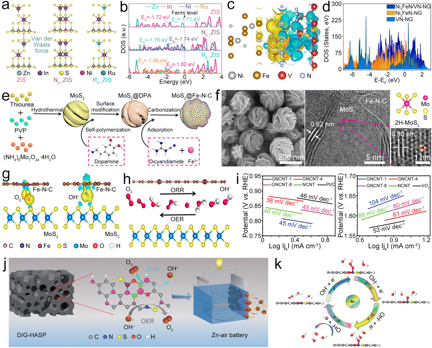 | ||
| Fig. 17 (a) Models of ZIS, N0.1ZIS, and R0.1ZIS. (b) PDOS of different sample models and the corresponding d-band centers. Reproduced with permission from ref. 188. Copyright 2022, Wiley-VCH. (c) Differential charge density diagram of Ni3FeN/VN; (d) total electronic DOS of Ni3FeN/VN, Ni3FeN and VN. Reproduced with permission from ref. 191. Copyright 2022, Elsevier. (e) Diagram of the synthesis of MoS2@Fe–N–C. (f) SEM and HRTEM images of MoS2@Fe–N–C, and the structural model of 2H-MoS2. (g) Electron density difference plots of MoS2@Fe–N–C with adsorbed O2 and OH−, respectively. (h) Schematic of O2 intercalation at the MoS2/Fe–N–C interface, and the production of OH− during the ORR and OER processes. Reproduced with permission from ref. 192. Copyright 2021, National Academy of Science. (i) Tafel plots of GNCNTs, Pt/C and IrO2 for the ORR and OER. Reproduced with permission from ref. 195. Copyright 2020, Wiley-VCH. (j) Diagram of the D/G-HASP catalyst. (k) Diagram of the 4e− process of the ORR on D/G-HASP. Reproduced with permission from ref. 199. Copyright 2021, Royal Society of Chemistry. | ||
The Ni3FeN/VN heterostructure can be encapsulated in NG (Ni3FeN/VN@NG) as a bifunctional electrocatalyst.191 In the Ni3FeN/VN heterostructure, the V site donates electrons to the Fe and Ni sites, enabling the total electron transfer from VN to Ni3FeN and therefore enhancing the electron conduction between VN and Ni3FeN (Fig. 17c) and ameliorating the adsorption/desorption strength for the intermediates. In addition, the benefits of electronic coupling of Ni3FeN and VN enable the higher electron density at the Ef (Fig. 17d). The improved conductivity between Ni3FeN and VN can thus be achieved, which can not only promote electron transfer and enable more electrons to involve in oxygen catalytic reaction, but also generate more active sites at the heterointerface. Benefiting from these merits, Ni3FeN/VN@NG exhibited a low ΔE of 0.69 V, and the ZAB based on the Ni3FeNVN@NG catalyst shows good cycle stability and a high PPD of up to 168 mW cm−2. Lin et al. reported a strategy (Fig. 17e) for fabricating crumpled nanospheres (Fig. 17f) composed of the MoS2 core blanketed by Fe–N–C coordination (MoS2@Fe–N–C) as the bifunctional electrocatalyst for ZABs.192 In this composite, the MoS2 layer loses electrons (cyan in Fig. 17g), while *O2 and *OH intermediates gain electrons (yellow in Fig. 17g), which help the electron transfer to adsorbed O2 and OH− on Fe–N–C, thus facilitating the *OOH formation (Fig. 17h). Moreover, the synergy between the MoS2 and Fe–N–C boundary constructed by the interfacial charge transfer from Fe–N–C to MoS2 and single Fe sites could reduce the reaction energy barriers, which could lead to high catalytic activity of MoS2@Fe–N–C. Consequently, the MoS2@Fe–N–C based ZAB exhibited superior cycling stability at high current density.
3.3. Metal-free carbonaceous materials
By virtue of their low-cost, superior electrocatalytic activity, good stability and environmental friendliness, metal-free carbonaceous catalysts are considered as promising alternatives to replace noble metal-based air electrodes for ZABs.145 Compared to noble metal-based catalysts, such as Pt and Pd commonly employed in air electrodes, metal-free carbonaceous catalysts offer significantly more cost-effective alternatives. At the same time, carbonaceous materials possess high catalytic activity for the ORR/OER, which is essential for high-performance ZABs. What's more, carbon-based catalysts have also demonstrated robust stability under extreme operating conditions, including high temperatures and acidic environments. More importantly, using metal-free carbonaceous catalysts could reduce the environmental impact of ZABs by eliminating the use of toxic and scarce noble metals. Up to now, researchers have explored different kinds of carbonaceous materials, including carbon nanotubes, graphene, activated carbon, and so on, as potential bifunctional catalysts for the air cathodes of ZABs.193,194 Additionally, various strategies for improving the electrocatalytic activity and stability of carbonaceous catalysts have been investigated, such as doping with heteroatoms, surface functionalization, and hybridization with other materials.2D graphene and N-doped carbon nanotubes (GNCNTs) can be fabricated via in situ growing ZIF-67 on GO followed by annealing treatment.195 The obtained GNCNTs with hierarchical nanostructure could exhibit a low Tafel slope for the ORR and OER (Fig. 17i), retaining 97% of the initial current and almost no loss in E1/2 after the 60![[thin space (1/6-em)]](https://www.rsc.org/images/entities/char_2009.gif) 000 s test, which is mainly attributed to the high surface area and abundant active M–N–C species with fast electron transfer, high kinetic activity, and outstanding stability, and could be used as a bifunctional electrocatalyst for oxygen reactions. As a result, the assembled ZAB based on the GNCNT air cathode exhibited a high PPD of 253 mW cm−2 along with good stability of 3000 h and 9000 cycles. Similarly, ZIF-67 can also in situ grow on the glucose-derived continuous porous carbon to synthesize the 3D interconnected architecture of the NCNT matrix (NCNTM).196 Abundant active M–N–C sites and hierarchical nanocarbon architecture endow the NCNTM with good activity and stability for oxygen reactions, resulting in a PPD of 220 mW cm−2 along with a cycling stability of over 1600 h in the liquid-electrolyte ZAB, as well as a PPD of 176 mW cm−2 in a solid-state ZAB. These works present a low-cost, straightforward, and feasible approach to synthesize high-performance oxygen electrocatalysts for ZABs. Additionally, carbon nanospheres with N-enriched edge (N-CNSP) and porous architecture can be fabricated by an activated carbon matrix-assisted strategy.197 High surface area and rich pores with defects exposed at the edge sites result in plentiful edge N active sites, which could increase the ORR/OER catalytic activities, leading to the assembled ZAB with the N-CNSP electrocatalyst delivering an OCV of 1.48 V, a large PPD of 160 mW cm−3, and a long cycling stability of over 1000 cycles.
000 s test, which is mainly attributed to the high surface area and abundant active M–N–C species with fast electron transfer, high kinetic activity, and outstanding stability, and could be used as a bifunctional electrocatalyst for oxygen reactions. As a result, the assembled ZAB based on the GNCNT air cathode exhibited a high PPD of 253 mW cm−2 along with good stability of 3000 h and 9000 cycles. Similarly, ZIF-67 can also in situ grow on the glucose-derived continuous porous carbon to synthesize the 3D interconnected architecture of the NCNT matrix (NCNTM).196 Abundant active M–N–C sites and hierarchical nanocarbon architecture endow the NCNTM with good activity and stability for oxygen reactions, resulting in a PPD of 220 mW cm−2 along with a cycling stability of over 1600 h in the liquid-electrolyte ZAB, as well as a PPD of 176 mW cm−2 in a solid-state ZAB. These works present a low-cost, straightforward, and feasible approach to synthesize high-performance oxygen electrocatalysts for ZABs. Additionally, carbon nanospheres with N-enriched edge (N-CNSP) and porous architecture can be fabricated by an activated carbon matrix-assisted strategy.197 High surface area and rich pores with defects exposed at the edge sites result in plentiful edge N active sites, which could increase the ORR/OER catalytic activities, leading to the assembled ZAB with the N-CNSP electrocatalyst delivering an OCV of 1.48 V, a large PPD of 160 mW cm−3, and a long cycling stability of over 1000 cycles.
In addition to single heteroatom doping, multi-atom co-doped carbon materials also exhibit excellent ORR and OER properties, which have also been extensively studied for preparing air electrode catalysts for ZABs. Compared with single-atom doped carbon, multi-atom co-doped carbonaceous materials have the following advantages: (1) multi-atom co-doping can lead to synergistic effects, resulting in better catalytic activity compared to single-atom doped carbon materials. The co-doping of multiple atoms can create more active sites on the catalyst surface, which can enhance the electrocatalytic performance; (2) multi-atom co-doping can promote the stability of the catalyst by increasing the resistance to oxidation, corrosion, and agglomeration, leading to a longer lifespan and better performance of the catalyst; (3) multi-atom co-doping can also lead to improved selectivity, reducing side reactions and improving the efficiency of the catalyst; and (4) the electronic properties of multi-atom co-doped carbon materials can be tuned by adjusting the type and concentration of the dopant atoms, which can improve the charge transfer efficiency and promote the ORR in ZABs. Therefore, multi-atom co-doped carbon materials have superior catalytic performance, stability, selectivity, and tunable electronic properties compared to single-atom doped carbon materials, making them promising candidates for developing high-performance catalysts for ZABs.
Based on these merits, metal-free 3D porous N and S co-doped carbon (NSC) was prepared as an ORR/OER catalyst for ZABs.198 Co-doping with N and S could lower ORR/OER overpotentials of carbon, enabling the graphitic N, S co-doped graphene and pyridinic N, S co-doped graphene to show lower energy barriers and overpotentials in the RDS of ORR/OER processes than the sole N or S doped graphene. Consequently, the synergistic interplay of N and S endows the NSC catalyst with superior bifunctional catalytic activity, which leads to the assembled ZAB demonstrating high PPD along with robust cycling stability. Yasin et al. reported a porous asphaltene nanomaterial with N, O, and S co-doping (NOS-ASP), which possesses the synergy of defective/graphitic edges via a fast fractionation approach (Fig. 17j).199 The calculation of reaction through 4e− pathways (Fig. 17k) shows that the ΔG is downhill for N and S-site asphaltene and defective graphene, and the overpotentials required for the ORR and OER at N, O, and S sites in NOS-ASP are lower than those for asphaltene with the sole N, S, or O doping and also lower than those of defective or pristine graphene, indicating that the defective/graphitic synergy and heteroatom doping are beneficial for promoting the reaction kinetics of NOS-ASP. Thus, the NOS-ASP bifunctional electrocatalyst based ZAB revealed a PPD of 235 mW cm−2 and good cycling durability.
However, it should be noted that the reported bifunctional catalysts of metal-free carbonaceous materials may be a subject of debate and even this topic is highlighted in this review, because the catalytic activity observed in these materials may originate from trace metal impurities, for example M–N–C sites mentioned in the above catalyst. Research has shown that impurities are always present in 1D and 2D materials (including carbon nanotubes, graphene, and their composites), and these impurities have a variety of effects on electrocatalysis. In many cases, these impurities catalyze electrochemical reactions, while in other cases, they may inhibit reactions. It is worth noting that the type of electrocatalytically active impurity varies among materials. In the case of metal-free carbonaceous materials, metal impurities may be the main cause. Therefore, we should take a fresh look at metal-free carbonaceous catalysts, where trace impurities at single atomic sites may play a crucial catalytic role, which need to be further identified through high-end analytical techniques.200
4. Conclusions and perspectives
ZABs have been under development for more than 100 years, but there are still many problems in their large-scale applications. Therefore, a large number of bifunctional electrocatalysts for both the ORR and OER are widely studied to seek to accelerate the practical applications of ZABs. In this review, we analyzed the advantages and problems of ZABs, systematically summarized the research status of bifunctional catalysts in recent 5 years, and explained the mechanism of various types of bifunctional catalysts in detail. The future development of bifunctional catalysts for ZABs is a critical area of research and innovation. Improving the efficiency, stability, and cost-effectiveness of these catalysts is essential to unlock the full potential of ZABs for various applications, such as EVs, grid storage, and portable electronics. For the future development of bifunctional catalysts for advanced ZABs, the following views are put forward here.(1) Tailoring catalyst composition and structure
Researchers concentrate their efforts on tailoring the composition and structure of bifunctional catalysts to optimize their activity and stability. These efforts include engineering catalysts with specific crystal structures, surface functionalities, and active sites to promote the desired electrochemical reactions in a more efficient way. The use of computational modeling and machine learning techniques would aid in predicting and designing new catalyst materials with target properties.(2) Non-precious metal catalysts
Efforts to design non-precious metal catalysts for oxygen reactions continue to gain momentum. M–N–C composites and other carbon-based materials, doped with transition metals, have been explored for their excellent catalytic activity and cost-effectiveness recently. Developing more efficient and abundant non-precious metal catalysts can significantly reduce the overall cost of ZABs and promote their commercial viability.(3) Composite catalysts
The use of composite catalysts, combining both precious and non-precious metal components, aims to capitalize on the synergistic effects of different materials. These composite catalysts seek to enhance catalytic activity, improve stability, and address scalability concerns. The development of composite catalysts allows for a balance between performance and cost, offering an attractive alternative for ZABs.(4) Stability and durability
One of the significant challenges of ZABs is maintaining the long-term stability and durability of the catalysts. Catalyst degradation during cycling is a critical factor that significantly impacts the overall performance of ZABs, leading to diminished efficiency and a reduction in battery lifespan. Future research should focus on developing catalysts with enhanced stability, resistance to poisoning, and the ability to prevent surface reconstruction to ensure long-lasting and reliable performance.(5) Scalability and manufacturing
As the demand for energy storage solutions continues to grow, the scalability and cost-effectiveness of catalyst manufacturing have become crucial factors. Future developments will focus on optimizing catalyst synthesis processes, such as scalable and cost-efficient methods for catalyst production, to enable large-scale commercialization of ZABs.(6) Integration with other technologies
Anticipated advancements in the development of bifunctional catalysts are expected to involve their integration with other burgeoning technologies. Notably, progress in the realms of advanced materials science, electrolyte chemistry, and innovative battery design will be crucial in augmenting the overall performance of ZABs and in tackling specific challenges inherent to these systems.(7) Cross-disciplinary collaborations
Developing efficient and stable bifunctional electrocatalysts will require cross-disciplinary collaborations between material scientists, electrochemists, chemical engineers, and computational researchers. By leveraging diverse expertise, innovative solutions can be discovered more efficiently and effectively.In all, the future development of bifunctional catalysts for ZABs is a dynamic and exciting field. Continued research and technological advancements in catalyst materials and design hold the promise for significantly improving the performance, cost, and scalability of ZABs, making them a competitive and environmentally friendly energy storage solution for various applications.
Conflicts of interest
There are no conflicts to declare.Acknowledgements
This work was financially supported by the National Key R & D Program of China (2021YFB2400400), the National Natural Science Foundation of China (no. 22279016, 22005092, 52073143, and 52131306), the Natural Science Foundation of Hunan Province (no. 2021JJ40046), the Project on Carbon Emission Peak and Neutrality of Jiangsu Province (BE2022031-4), the Fundamental Research Funds for the Central Universities (2242023R10001), and the Start-up Research Fund of Southeast University (RF1028623005).References
- J.-N. Liu, C.-X. Zhao, J. Wang, D. Ren, B.-Q. Li and Q. Zhang, Energy Environ. Sci., 2022, 15, 4542–4553 RSC
.
- W. Sun, F. Wang, B. Zhang, M. Zhang, V. Küpers, X. Ji, C. Theile, P. Bieker, K. Xu and C. Wang, Science, 2021, 371, 46–51 CrossRef CAS PubMed
- D. Aurbach, Electrochim. Acta, 2002, 21, 3561 CrossRef
-
J. Kim and G. Kim, Zinc-Air Batteries: Introduction, Design Principles and Emerging Technologies, 2022, pp. 261–280 Search PubMed
-
G. G. Yadav, X. Wei and M. Meeus, Electrochemical Power Sources: Fundamentals, Systems, and Applications, Elsevier, 2021, pp. 23–45 Search PubMed
- Y. Li and H. Dai, Chem. Soc. Rev., 2014, 43, 5257–5275 RSC
- V. Neburchilov, H. Wang, J. J. Martin and W. Qu, J. Power Sources, 2010, 195, 1271–1291 CrossRef CAS
- H. Oman, IEEE Aero. El. Sys. Mag., 1999, 14, 19–21 Search PubMed
- J. Yi, P. Liang, X. Liu, K. Wu, Y. Liu, Y. Wang, Y. Xia and J. Zhang, Energy Environ. Sci., 2018, 11, 3075–3095 RSC
- Z. Zhao, X. Fan, J. Ding, W. Hu, C. Zhong and J. Lu, ACS Energy Lett., 2019, 4, 2259–2270 CrossRef CAS
- H. F. Wang, C. Tang and Q. Zhang, Adv. Funct. Mater., 2018, 28, 1803329 CrossRef
- S. Ren, X. Duan, S. Liang, M. Zhang and H. Zheng, J. Mater. Chem. A, 2020, 8, 6144–6182 RSC
- D. Xiao, X. Lv, J. Fan, Q. Li and Z. Chen, Energy Mater., 2023, 3, 300007 CAS
- D. Stock, S. Dongmo, J. R. Janek and D. Schröder, ACS Energy Lett., 2019, 4, 1287–1300 CrossRef CAS
- D. Yang, H. Tan, X. Rui and Y. Yu, Electrochem. Energy Rev., 2019, 2, 395–427 CrossRef CAS
- J. Fu, Z. P. Cano, M. G. Park, A. Yu, M. Fowler and Z. Chen, Adv. Mater., 2017, 29, 1604685 CrossRef PubMed
- N. Shang, K. Wang, M. Wei, Y. Zuo, P. Zhang, H. Wang, Z. Chen and P. Pei, J. Mater. Chem. A, 2022, 10, 16369–16389 RSC
- G. Li, K. Sheng, Y. Lei, F. Zhang, J. Yang, B. Chang, L. Zheng and X. Wang, Energy Mater., 2023, 3, 300021 CAS
- Z. Yin, R. He, H. Xue, J. Chen, Y. Wang, X. Ye, N. Xu, J. Qiao and H. Huang, Energy Mater., 2022, 2, 200021 CrossRef CAS
- M. Luo, W. Sun, B. B. Xu, H. Pan and Y. Jiang, Adv. Energy Mater., 2021, 11, 2002762 CrossRef CAS
- X. Zhu, C. Hu, R. Amal, L. Dai and X. Lu, Energy Environ. Sci., 2020, 13, 4536–4563 RSC
- P. Tan, B. Chen, H. Xu, H. Zhang, W. Cai, M. Ni, M. Liu and Z. Shao, Energy Environ. Sci., 2017, 10, 2056–2080 RSC
- L. Peng, L. Shang, T. Zhang and G. I. Waterhouse, Adv. Energy Mater., 2020, 10, 2003018 CrossRef CAS
- W.-F. Wu, X. Yan and Y. Zhan, Chem. Eng. J., 2023, 451, 138608 CrossRef CAS
- D. Yang, L. Zhang, X. Yan and X. Yao, Small Methods, 2017, 1, 1700209 CrossRef
- J. Fu, R. Liang, G. Liu, A. Yu, Z. Bai, L. Yang and Z. Chen, Adv. Mater., 2019, 31, 1805230 CrossRef PubMed
- T. Zhou, N. Zhang, C. Wu and Y. Xie, Energy Environ. Sci., 2020, 13, 1132–1153 RSC
- P. Wang, T. Jia and B. Wang, J. Electrochem. Soc., 2020, 167, 110564 CrossRef CAS
- X. Liu, G. Zhang, L. Wang and H. Fu, Small, 2021, 17, 2006766 CrossRef CAS PubMed
- T. Zhang, N. Wu, Y. Zhao, X. Zhang, J. Wu, J. Weng, S. Li, F. Huo and W. Huang, Adv. Sci., 2022, 9, 2103954 CrossRef CAS PubMed
- H. Liu, F. Yu, K. Wu, G. Xu, C. Wu, H. K. Liu and S. X. Dou, Small, 2022, 18, 2106635 CrossRef CAS PubMed
- J. Zhang, Q. Zhou, Y. Tang, L. Zhang and Y. Li, Chem. Sci., 2019, 10, 8924–8929 RSC
- Y. Arafat, M. R. Azhar, Y. Zhong, X. Xu, M. O. Tadé and Z. Shao, Nano-Micro Lett., 2020, 12, 130 CrossRef CAS PubMed
- X. Yu, T. Zhou, J. Ge and C. Wu, ACS Mater. Lett., 2020, 2, 1423–1434 CrossRef CAS
- G. Fu, Y. Tang and J. M. Lee, ChemElectroChem, 2018, 5, 1424–1434 CrossRef CAS
- F. Yang, X. Gao, J. Xie, X. Liu, J. Jiang and X. Lu, Small Struct., 2021, 2, 2100144 CrossRef CAS
- M. Wu, G. Zhang, M. Wu, J. Prakash and S. Sun, Energy Storage Mater., 2019, 21, 253–286 CrossRef
- P. Gu, M. Zheng, Q. Zhao, X. Xiao, H. Xue and H. Pang, J. Materials Chem. A, 2017, 5, 7651–7666 RSC
- L. Zhong, C. Jiang, M. Zheng, X. Peng, T. Liu, S. Xi, X. Chi, Q. Zhang, L. Gu and S. Zhang, ACS Energy Lett., 2021, 6, 3624–3633 CrossRef CAS
- Y. Li, K. Xu, Q. Zhang, Z. Zheng, S. Li, Q. Zhao, C. Li, C. Dong, Z. Mei, F. Pan and S. Dou, J. Energy Chem., 2022, 66, 100–106 CrossRef CAS
- M. Xiao, Z. Xing, Z. Jin, C. Liu, J. Ge, J. Zhu, Y. Wang, X. Zhao and Z. Chen, Adv. Mater., 2020, 32, 2004900 CrossRef CAS PubMed
- M. Jiao, W. Song, K. Li, Y. Wang and Z. Wu, J. Phys. Chem. C, 2016, 120, 8804–8812 CrossRef CAS
- Y. Meng, J.-C. Li, S.-Y. Zhao, C. Shi, X.-Q. Li, L. Zhang, P.-X. Hou, C. Liu and H.-M. Cheng, Appl. Catal., B, 2021, 294, 120239 CrossRef CAS
- F. Dong, M. Wu, Z. Chen, X. Liu, G. Zhang, J. Qiao and S. Sun, Nano-Micro Lett., 2022, 14, 36 CrossRef CAS PubMed
- Q. Zhang and J. Guan, Energy Environ. Mater., 2021, 4, 307–335 CrossRef CAS
- H. Zhang, H. Guang, R. Li, X. Lu, H. Xu, D. Wang, L. Xiao, J. Zhang, M. An and P. Yang, J. Mater. Chem. A, 2022, 10, 21797–21815 RSC
- X. Zhao, X. Li, Z. Bi, Y. Wang, H. Zhang, X. Zhou, Q. Wang, Y. Zhou, H. Wang and G. Hu, J. Energy Chem., 2022, 66, 514–524 CrossRef CAS
- L. Yang, X. Zhang, L. Yu, J. Hou, Z. Zhou and R. Lv, Adv. Mater., 2022, 34, 2105410 CrossRef CAS PubMed
- W. Cheng, P. Yuan, Z. Lv, Y. Guo, Y. Qiao, X. Xue, X. Liu, W. Bai, K. Wang and Q. Xu, Appl. Catal., B, 2020, 260, 118198 CrossRef CAS
- P. Li, H. Wang, W. Fan, M. Huang, J. Shi, Z. Shi and S. Liu, Chem. Eng. J., 2021, 421, 129704 CrossRef CAS
- L. Zong, X. Chen, S. Liu, K. Fan, S. Dou, J. Xu, X. Zhao, W. Zhang, Y. Zhang and W. Wu, J. Energy Chem., 2021, 56, 72–79 CrossRef CAS
- Y.-W. Li, W.-J. Zhang, J. Li, H.-Y. Ma, H.-M. Du, D.-C. Li, S.-N. Wang, J.-S. Zhao, J.-M. Dou and L. Xu, ACS Appl. Mater. Interfaces, 2020, 12, 44710–44719 CrossRef CAS PubMed
- X. Yang, X. Zheng, H. Li, B. Luo, Y. He, Y. Yao, H. Zhou, Z. Yan, Y. Kuang and Z. Huang, Adv. Funct. Mater., 2022, 32, 2200397 CrossRef CAS
- K. Wu, L. Zhang, Y. Yuan, L. Zhong, Z. Chen, X. Chi, H. Lu, Z. Chen, R. Zou and T. Li, Adv. Mater., 2020, 32, 2002292 CrossRef CAS PubMed
- H. Jiang, Q. He, Y. Zhang and L. Song, Acc. Chem. Res., 2018, 51, 2968–2977 CrossRef CAS PubMed
- J. Chen, H. Chen, T. Yu, R. Li, Y. Wang, Z. Shao and S. Song, Electrochem. Energy Rev., 2021, 4, 566–600 CrossRef CAS
- L. Gao, X. Cui, C. D. Sewell, J. Li and Z. Lin, Chem. Soc. Rev., 2021, 50, 8428–8469 RSC
- K. Kawashima, R. A. Márquez, L. A. Smith, R. R. Vaidyula, O. A. Carrasco-Jaim, Z. Wang, Y. J. Son, C. L. Cao and C. B. Mullins, Chem. Rev., 2023, 123, 12795–13208 CrossRef CAS PubMed
- S. Wang, S. Chen, L. Ma and J. A. Zapien, Mater. Today Energy, 2021, 20, 100659 CrossRef CAS
- N. Yu, H. Chen, J. Kuang, K. Bao, W. Yan, J. Ye, Z. Yang, Q. Huang, Y. Wu and S. Sun, Nano Res., 2022, 15, 7209–7219 CrossRef CAS
- L. Liu, Y. Wang, F. Yan, C. Zhu, B. Geng, Y. Chen and S. L. Chou, Small Methods, 2020, 4, 1900571 CrossRef CAS
- T. Liu, J. Mou, Z. Wu, C. Lv, J. Huang and M. Liu, Adv. Funct. Mater., 2020, 30, 2003407 CrossRef CAS
- Q. Zhou, Z. Zhang, J. Cai, B. Liu, Y. Zhang, X. Gong, X. Sui, A. Yu, L. Zhao and Z. Wang, Nano Energy, 2020, 71, 104592 CrossRef CAS
- Q. Lu, H. Wu, X. Zheng, Y. Chen, A. L. Rogach, X. Han, Y. Deng and W. Hu, Adv. Sci., 2021, 8, 2101438 CrossRef CAS PubMed
- H. Ge, G. Li, J. Shen, W. Ma, X. Meng and L. Xu, Appl. Catal., B, 2020, 275, 119104 CrossRef CAS
- N.-F. Yu, C. Wu, W. Huang, Y.-H. Chen, D.-Q. Ruan, K.-L. Bao, H. Chen, Y. Zhang, Y. Zhu and Q.-H. Huang, Nano Energy, 2020, 77, 105200 CrossRef CAS
- X. Cui, Y. Liu, G. Han, M. Cao, L. Han, B. Zhou, S. Mehdi, X. Wu, B. Li and J. Jiang, Small, 2021, 17, 2101607 CrossRef CAS PubMed
- Y. Tan, W. Zhu, Z. Zhang, W. Wu, R. Chen, S. Mu, H. Lv and N. Cheng, Nano Energy, 2021, 83, 105813 CrossRef CAS
- J. Qin, Z. Liu, D. Wu and J. Yang, Appl. Catal., B, 2020, 278, 119300 CrossRef CAS
- Y. Tian, L. Xu, M. Li, D. Yuan, X. Liu, J. Qian, Y. Dou, J. Qiu and S. Zhang, Nano-Micro Lett., 2021, 13, 3 CrossRef PubMed
- W. Li, Y. Li, H. Fu, G. Yang, Q. Zhang, S. Chen and F. Peng, Chem. Eng. J., 2020, 381, 122683 CrossRef CAS
- C. Xia, L. Huang, D. Yan, A. I. Douka, W. Guo, K. Qi and B. Y. Xia, Adv. Funct. Mater., 2021, 31, 2105021 CrossRef CAS
- J. H. Park, C. H. Lee, J. M. Ju, J. H. Lee, J. Seol, S. U. Lee and J. H. Kim, Adv. Funct. Mater., 2021, 31, 2101727 CrossRef CAS
- Y. Zhang, B. Ouyang, G. Long, H. Tan, Z. Wang, Z. Zhang, W. Gao, R. S. Rawat and H. J. Fan, Sci. China: Chem., 2020, 63, 890–896 CrossRef CAS
- Y. Tian, X. Liu, L. Xu, D. Yuan, Y. Dou, J. Qiu, H. Li, J. Ma, Y. Wang and D. Su, Adv. Funct. Mater., 2021, 31, 2101239 CrossRef CAS
- Y. Rao, S. Chen, Q. Yue and Y. Kang, ACS Catal., 2021, 11, 8097–8103 CrossRef CAS
- L. Lv, D. Zha, Y. Ruan, Z. Li, X. Ao, J. Zheng, J. Jiang, H. M. Chen, W.-H. Chiang and J. Chen, ACS Nano, 2018, 12, 3042–3051 CrossRef CAS PubMed
- H. Han, K. M. Kim, H. Choi, G. Ali, K. Y. Chung, Y.-R. Hong, J. Choi, J. Kwon, S. W. Lee and J. W. Lee, ACS Catal., 2018, 8, 4091–4102 CrossRef CAS
- J. Azadmanjiri, V. K. Srivastava, P. Kumar, J. Wang and A. Yu, J. Mater. Chem. A, 2018, 6, 13509–13537 RSC
- L.-N. Lu, Y.-L. Luo, H.-J. Liu, Y.-X. Chen, K. Xiao and Z.-Q. Liu, Chem. Eng. J., 2022, 427, 132041 CrossRef CAS
- N. Logeshwaran, S. Ramakrishnan, S. S. Chandrasekaran, M. Vinothkannan, A. R. Kim, S. Sengodan, D. B. Velusamy, P. Varadhan, J.-H. He and D. J. Yoo, Appl. Catal., B, 2021, 297, 120405 CrossRef CAS
- X. F. Lu, S. L. Zhang, E. Shangguan, P. Zhang, S. Gao and X. W. Lou, Adv. Sci., 2020, 7, 2001178 CrossRef CAS PubMed
- Y. Niu, M. Xiao, J. Zhu, T. Zeng, J. Li, W. Zhang, D. Su, A. Yu and Z. Chen, J. Mater. Chem. A, 2020, 8, 9177–9184 RSC
- X. W. Lv, W. S. Xu, W. W. Tian, H. Y. Wang and Z. Y. Yuan, Small, 2021, 17, 2101856 CrossRef CAS PubMed
- M. Wu, G. Zhang, N. Chen, Y. Hu, T. Regier, D. Rawach and S. Sun, ACS Energy Lett., 2021, 6, 1153–1161 CrossRef CAS
- Y. Han, H. Duan, C. Zhou, H. Meng, Q. Jiang, B. Wang, W. Yan and R. Zhang, Nano Lett., 2022, 22, 2497–2505 CrossRef CAS PubMed
- D. Yan, C. Xia, C. He, Q. Liu, G. Chen, W. Guo and B. Y. Xia, Small, 2022, 18, 2106606 CrossRef CAS PubMed
- A. I. Douka, Y. Xu, H. Yang, S. Zaman, Y. Yan, H. Liu, M. A. Salam and B. Y. Xia, Adv. Mater., 2020, 32, 2002170 CrossRef CAS PubMed
- Z. Xu, J. Zhu, J. Shao, Y. Xia, J. Tseng, C. Jiao, G. Ren, P. Liu, G. Li and R. Chen, Energy Storage Mater., 2022, 47, 365–375 CrossRef
- R. Wang, H. Yang, N. Lu, S. Lei, D. Jia, Z. Wang, Z. Liu, X. Wu, H. Zheng and S. Ali, Chem. Eng. J., 2022, 433, 134500 CrossRef CAS
- J. C. Li, Y. Meng, L. Zhang, G. Li, Z. Shi, P. X. Hou, C. Liu, H. M. Cheng and M. Shao, Adv. Funct. Mater., 2021, 31, 2103360 CrossRef CAS
- H. Luo, W. J. Jiang, S. Niu, X. Zhang, Y. Zhang, L. P. Yuan, C. He and J. S. Hu, Small, 2020, 16, 2001171 CrossRef CAS PubMed
- C. X. Zhao, J. N. Liu, J. Wang, D. Ren, J. Yu, X. Chen, B. Q. Li and Q. Zhang, Adv. Mater., 2021, 33, 2008606 CrossRef CAS PubMed
- H. Yang, S. Gao, D. Rao and X. Yan, Energy Storage Mater., 2022, 46, 553–562 CrossRef
- Q. Wang, Q. Feng, Y. Lei, S. Tang, L. Xu, Y. Xiong, G. Fang, Y. Wang, P. Yang and J. Liu, Nat. Commun., 2022, 13, 3689 CrossRef CAS PubMed
- Q. Wang, K. Ye, L. Xu, W. Hu, Y. Lei, Y. Zhang, Y. Chen, K. Zhou, J. Jiang and J. M. Basset, Chem. Commun., 2019, 55, 14801–14804 RSC
- H. Jiang, J. Xia, L. Jiao, X. Meng, P. Wang, C.-S. Lee and W. Zhang, Appl. Catal., B, 2022, 310, 121352 CrossRef CAS
- X. Zheng, X. Cao, Z. Sun, K. Zeng, J. Yan, P. Strasser, X. Chen, S. Sun and R. Yang, Appl. Catal., B, 2020, 272, 118967 CrossRef CAS
- X. Chen, J. Chang and Q. Ke, Carbon, 2018, 126, 53–57 CrossRef CAS
- P. Liu, J. Ran, B. Xia, S. Xi, D. Gao and J. Wang, Nano-Micro Lett., 2020, 12, 68 CrossRef CAS PubMed
- L. Yan, Y. Xu, P. Chen, S. Zhang, H. Jiang, L. Yang, Y. Wang, L. Zhang, J. Shen and X. Zhao, Adv. Mater., 2020, 32, 2003313 CrossRef CAS PubMed
- J. Zhang, T. Wang, D. Xue, C. Guan, P. Xi, D. Gao and W. Huang, Energy Storage Mater., 2020, 25, 202–209 CrossRef
- J. Greeley, J. K. Nørskov and M. Mavrikakis, Annu. Rev. Phys. Chem., 2002, 53, 319–348 CrossRef CAS PubMed
- Y. Zheng, Y. Jiao, M. Jaroniec and S. Z. Qiao, Angew. Chem., Int. Ed., 2015, 54, 52–65 CrossRef CAS PubMed
- Z. Chen, Y. Song, J. Cai, X. Zheng, D. Han, Y. Wu, Y. Zang, S. Niu, Y. Liu and J. Zhu, Angew. Chem., Int. Ed., 2018, 57, 5076–5080 CrossRef CAS PubMed
- K. Ding, J. Hu, J. Luo, W. Jin, L. Zhao, L. Zheng, W. Yan, B. Weng, H. Hou and X. Ji, Nano Energy, 2022, 91, 106675 CrossRef CAS
- P. Du, K. Hu, J. Lyu, H. Li, X. Lin, G. Xie, X. Liu, Y. Ito and H.-J. Qiu, Appl. Catal., B, 2020, 276, 119172 CrossRef CAS
- N. K. Wagh, S. S. Shinde, C. H. Lee, J.-Y. Jung, D.-H. Kim, S.-H. Kim, C. Lin, S. U. Lee and J.-H. Lee, Appl. Catal., B, 2020, 268, 118746 CrossRef CAS
- N. Wang, S. Ning, X. Yu, D. Chen, Z. Li, J. Xu, H. Meng, D. Zhao, L. Li and Q. Liu, Appl. Catal., B, 2022, 302, 120838 CrossRef CAS
- S. Sun, X. Zhou, B. Cong, W. Hong and G. Chen, ACS Catal., 2020, 10, 9086–9097 CrossRef CAS
- Y. Zheng, D.-S. Yang, J. M. Kweun, C. Li, K. Tan, F. Kong, C. Liang, Y. J. Chabal, Y. Y. Kim and M. Cho, Nano Energy, 2016, 30, 443–449 CrossRef CAS
- X. Shen, T. Nagai, F. Yang, L. Q. Zhou, Y. Pan, L. Yao, D. Wu, Y.-S. Liu, J. Feng and J. Guo, J. Am. Chem. Soc., 2019, 141, 9463–9467 CrossRef CAS PubMed
- M. Jiao, Q. Zhang, C. Ye, R. Gao, L. Dai, G. Zhou and H.-M. Cheng, ACS Nano, 2022, 16, 13223–13231 CrossRef CAS PubMed
- Z. Pei, Z. Yuan, C. Wang, S. Zhao, J. Fei, L. Wei, J. Chen, C. Wang, R. Qi and Z. Liu, Angew. Chem., Int. Ed., 2020, 59, 4793–4799 CrossRef CAS PubMed
- L. Liu, X. Zhang, F. Yan, B. Geng, C. Zhu and Y. Chen, J. Mater. Chem. A, 2020, 8, 18162–18172 RSC
- T. Tang, W.-J. Jiang, X.-Z. Liu, J. Deng, S. Niu, B. Wang, S.-F. Jin, Q. Zhang, L. Gu and J.-S. Hu, J. Am. Chem. Soc., 2020, 142, 7116–7127 CrossRef CAS PubMed
- Y. Niu, X. Teng, S. Gong, M. Xu, S.-G. Sun and Z. Chen, Nano-Micro Lett., 2021, 13, 126 CrossRef CAS PubMed
- B. Zhang, X. Zheng, O. Voznyy, R. Comin, M. Bajdich, M. García-Melchor, L. Han, J. Xu, M. Liu and L. Zheng, Science, 2016, 352, 333–337 CrossRef CAS PubMed
- C. Lai, J. Fang, X. Liu, M. Gong, T. Zhao, T. Shen, K. Wang, K. Jiang and D. Wang, Appl. Catal., B, 2021, 285, 119856 CrossRef CAS
- S. Chang, H. Zhang and Z. Zhang, J. Energy Chem., 2021, 56, 64–71 CrossRef CAS
- Q. Shi, Q. Liu, Y. Ma, Z. Fang, Z. Liang, G. Shao, B. Tang, W. Yang, L. Qin and X. Fang, Adv. Energy Mater., 2020, 10, 1903854 CrossRef CAS
- G. Zhou, G. Liu, X. Liu, Q. Yu, H. Mao, Z. Xiao and L. Wang, Adv. Funct. Mater., 2022, 32, 2107608 CrossRef CAS
- H. Zhang, M. Zhao, H. Liu, S. Shi, Z. Wang, B. Zhang, L. Song, J. Shang, Y. Yang and C. Ma, Nano Lett., 2021, 21, 2255–2264 CrossRef CAS PubMed
- H. Lei, Z. Wang, F. Yang, X. Huang, J. Liu, Y. Liang, J. Xie, M. S. Javed, X. Lu and S. Tan, Nano Energy, 2020, 68, 104293 CrossRef CAS
- Y. Niu, X. Teng, S. Gong and Z. Chen, J. Mater. Chem. A, 2020, 8, 13725–13734 RSC
- D. Chen, J. Zhu, X. Mu, R. Cheng, W. Li, S. Liu, Z. Pu, C. Lin and S. Mu, Appl. Catal., B, 2020, 268, 118729 CrossRef CAS
- X. Li, Y. Liu, H. Chen, M. Yang, D. Yang, H. Li and Z. Lin, Nano Lett., 2021, 21, 3098–3105 CrossRef CAS PubMed
- W.-W. Tian, J.-T. Ren and Z.-Y. Yuan, Appl. Catal., B, 2022, 317, 121764 CrossRef CAS
- K. Sheng, Q. Yi, A.-L. Chen, Y. Wang, Y. Yan, H. Nie and X. Zhou, ACS Appl. Mater. Interfaces, 2021, 13, 45394–45405 CrossRef CAS PubMed
- Z. Li, W. Niu, Z. Yang, N. Zaman, W. Samarakoon, M. Wang, A. Kara, M. Lucero, M. V. Vyas and H. Cao, Energy Environ. Sci., 2020, 13, 884–895 RSC
- J. Dong, H. Zhang, G. Xu, Z. Li, G. Li, W. Hu, D. Wu, G. Chen, X. Dai and J. Luo, Europhys. Lett., 2008, 83, 27006 CrossRef
- Z. Zhao, M. Li, L. Zhang, L. Dai and Z. Xia, Adv. Mater., 2015, 27, 6834–6840 CrossRef CAS PubMed
- D. Ren, J. Ying, M. Xiao, Y. P. Deng, J. Ou, J. Zhu, G. Liu, Y. Pei, S. Li and A. M. Jauhar, Adv. Funct. Mater., 2020, 30, 1908167 CrossRef CAS
- G. Fang, J. Gao, J. Lv, H. Jia, H. Li, W. Liu, G. Xie, Z. Chen, Y. Huang and Q. Yuan, Appl. Catal., B, 2020, 268, 118431 CrossRef CAS
- F. Cheng, J. Shen, B. Peng, Y. Pan, Z. Tao and J. Chen, Nat. Chem., 2011, 3, 79–84 CrossRef CAS PubMed
- B. Zhao, L. Zhang, D. Zhen, S. Yoo, Y. Ding, D. Chen, Y. Chen, Q. Zhang, B. Doyle and X. Xiong, Nat. Commun., 2017, 8, 14586 CrossRef CAS PubMed
- T. Ling, D.-Y. Yan, Y. Jiao, H. Wang, Y. Zheng, X. Zheng, J. Mao, X.-W. Du, Z. Hu and M. Jaroniec, Nat. Commun., 2016, 7, 12876 CrossRef CAS PubMed
- N.-F. Yu, W. Huang, K.-L. Bao, H. Chen, K. Hu, Y. Zhang, Q.-H. Huang, Y. Zhu and Y.-P. Wu, Dalton Trans., 2021, 50, 2093–2101 RSC
- J. Kuang, N. Yu, Z. Yang, Y. Zhang, L. Ji, J. Ye, W. Huang, Q. Huang, N. Tian and Y. Wu, Dalton Trans., 2023, 52, 4371–4381 RSC
- K.-L. Bao, J.-Y. Xu, N.-F. Yu, J.-B. Kuang, Z.-T. Yang, H. Chen, J.-L. Ye and Y.-P. Wu, Energy Fuel., 2022, 36, 6542–6551 CrossRef CAS
- A. Sumboja, M. Lübke, Y. Wang, T. An, Y. Zong and Z. Liu, Adv. Energy Mater., 2017, 7, 1700927 CrossRef
- Y. Meng, W. Song, H. Huang, Z. Ren, S.-Y. Chen and S. L. Suib, J. Am. Chem. Soc., 2014, 136, 11452–11464 CrossRef CAS PubMed
- D. M. Robinson, Y. B. Go, M. Mui, G. Gardner, Z. Zhang, D. Mastrogiovanni, E. Garfunkel, J. Li, M. Greenblatt and G. C. Dismukes, J. Am. Chem. Soc., 2013, 135, 3494–3501 CrossRef CAS PubMed
- I. Roche, E. Chaînet, M. Chatenet and J. Vondrák, J. Phys. Chem. C, 2007, 111, 1434–1443 CrossRef CAS
- Q. Tang, L. Jiang, J. Liu, S. Wang and G. Sun, ACS Catal., 2014, 4, 457–463 CrossRef CAS
- Y.-T. Weng and N.-L. Wu, Chem. Commun., 2013, 49, 10784–10786 RSC
- S. Song, W. Li, Y.-P. Deng, Y. Ruan, Y. Zhang, X. Qin and Z. Chen, Nano Energy, 2020, 67, 104208 CrossRef CAS
- J. Béjar, F. Espinosa-Magaña, M. Guerra-Balcázar, J. Ledesma-García, L. Álvarez-Contreras, N. Arjona and L. G. Arriaga, ACS Appl. Mater. Interfaces, 2020, 12, 53760–53773 CrossRef PubMed
- L. Yan, Z. Xu, W. Hu, J. Ning, Y. Zhong and Y. Hu, Nano Energy, 2021, 82, 105710 CrossRef CAS
- M. Jiao, Q. Zhang, C. Ye, Z. Liu, X. Zhong, J. Wang, C. Li, L. Dai, G. Zhou and H.-M. Cheng, Proc. Natl. Acad. Sci. U. S. A., 2022, 119, e2202202119 CrossRef CAS PubMed
- W. Zhang, J. Chang, G. Wang, Z. Li, M. Wang, Y. Zhu, B. Li, H. Zhou, G. Wang and M. Gu, Energy Environ. Sci., 2022, 15, 1573–1584 RSC
- M. Bajdich, M. García-Mota, A. Vojvodic, J. K. Nørskov and A. T. Bell, J. Am. Chem. Soc., 2013, 135, 13521–13530 CrossRef CAS PubMed
- Z.-F. Huang, J. Song, S. Dou, X. Li, J. Wang and X. Wang, Matter, 2019, 1, 1494–1518 CrossRef
- Q. Wang, X. Huang, Z. L. Zhao, M. Wang, B. Xiang, J. Li, Z. Feng, H. Xu and M. Gu, J. Am. Chem. Soc., 2020, 142, 7425–7433 CrossRef CAS PubMed
- C. Zhou, X. Chen, S. Liu, Y. Han, H. Meng, Q. Jiang, S. Zhao, F. Wei, J. Sun and T. Tan, J. Am. Chem. Soc., 2022, 144, 2694–2704 CrossRef CAS PubMed
- J. Kitchin, J. K. Nørskov, M. Barteau and J. Chen, J. Chem. Phys., 2004, 120, 10240–10246 CrossRef CAS PubMed
- H. B. Tao, L. Fang, J. Chen, H. B. Yang, J. Gao, J. Miao, S. Chen and B. Liu, J. Am. Chem. Soc., 2016, 138, 9978–9985 CrossRef CAS PubMed
- C. Zhou, S. Zhao, H. Meng, Y. Han, Q. Jiang, B. Wang, X. Shi, W. Zhang, L. Zhang and R. Zhang, Nano Lett., 2021, 21, 9633–9641 CrossRef CAS PubMed
- J. Ran, T. Wang, J. Zhang, Y. Liu, C. Xu, S. Xi and D. Gao, Chem. Mater., 2020, 32, 3439–3446 CrossRef CAS
- C. X. Zhao, J. N. Liu, B. Q. Li, D. Ren, X. Chen, J. Yu and Q. Zhang, Adv. Funct. Mater., 2020, 30, 2003619 CrossRef CAS
- Z. Shao, Q. Zhu, Y. Sun, Y. Zhang, Y. Jiang, S. Deng, W. Zhang, K. Huang and S. Feng, Adv. Mater., 2022, 34, 2110172 CrossRef CAS PubMed
- Y. Wang, Z. Li, P. Zhang, Y. Pan, Y. Zhang, Q. Cai, S. R. P. Silva, J. Liu, G. Zhang and X. Sun, Nano Energy, 2021, 87, 106147 CrossRef CAS
- Y. Chen, S. Hu, F. Nichols, F. Bridges, S. Kan, T. He, Y. Zhang and S. Chen, J. Mater. Chem. A, 2020, 8, 11649–11655 RSC
- H. Fei, J. Dong, Y. Feng, C. S. Allen, C. Wan, B. Volosskiy, M. Li, Z. Zhao, Y. Wang and H. Sun, Nat. Catal., 2018, 1, 63–72 CrossRef CAS
- X. Han, X. Ling, D. Yu, D. Xie, L. Li, S. Peng, C. Zhong, N. Zhao, Y. Deng and W. Hu, Adv. Mater., 2019, 31, 1905622 CrossRef CAS PubMed
- J. Wang, Z. Huang, W. Liu, C. Chang, H. Tang, Z. Li, W. Chen, C. Jia, T. Yao and S. Wei, J. Am. Chem. Soc., 2017, 139, 17281–17284 CrossRef CAS PubMed
- C.-C. Weng, J.-T. Ren, H.-Y. Wang, X.-W. Lv, Y.-J. Song, Y.-S. Wang, L. Chen, W.-W. Tian and Z.-Y. Yuan, Appl. Catal., B, 2022, 307, 121190 CrossRef CAS
- V. Jose, H. Hu, E. Edison, W. Manalastas Jr, H. Ren, P. Kidkhunthod, S. Sreejith, A. Jayakumar, J. M. V. Nsanzimana and M. Srinivasan, Small Methods, 2021, 5, 2000751 CrossRef CAS PubMed
- X. Duan, S. Ren, N. Pan, M. Zhang and H. Zheng, J. Mater. Chem. A, 2020, 8, 9355–9363 RSC
- Y. Jiao, Y. Zheng, M. Jaroniec and S. Z. Qiao, Chem. Soc. Rev., 2015, 44, 2060–2086 RSC
- J. Masa, W. Xia, I. Sinev, A. Zhao, Z. Sun, S. Grützke, P. Weide, M. Muhler and W. Schuhmann, Angew. Chem., Int. Ed., 2014, 53, 8508–8512 CrossRef CAS PubMed
- Y. He, X. Yang, Y. Li, L. Liu, S. Guo, C. Shu, F. Liu, Y. Liu, Q. Tan and G. Wu, ACS Catal., 2022, 12, 1216–1227 CrossRef CAS
- T. Cui, Y. P. Wang, T. Ye, J. Wu, Z. Chen, J. Li, Y. Lei, D. Wang and Y. Li, Angew. Chem., Int. Ed., 2022, 61, e202115219 CrossRef CAS
- X. Zhang, Y. Li, M. Jiang, J. Wei, X. Ding, C. Zhu, H. He, H. Lai and J. Shi, Chem. Eng. J., 2021, 426, 130758 CrossRef CAS
- F. Luo, J. Zhu, S. Ma, M. Li, R. Xu, Q. Zhang, Z. Yang, K. Qu, W. Cai and Z. Chen, Energy Storage Mater., 2021, 35, 723–730 CrossRef
- H. Sun, M. Wang, S. Zhang, S. Liu, X. Shen, T. Qian, X. Niu, J. Xiong and C. Yan, Adv. Funct. Mater., 2021, 31, 2006533 CrossRef CAS
- B. Hu, A. Huang, X. Zhang, Z. Chen, R. Tu, W. Zhu, Z. Zhuang, C. Chen, Q. Peng and Y. Li, Nano Res., 2021, 14, 3482–3488 CrossRef CAS
- Z. Li, Q. Wang, X. Bai, M. Wang, Z. Yang, Y. Du, G. E. Sterbinsky, D. Wu, Z. Yang and H. Tian, Energy Environ. Sci., 2021, 14, 5035–5043 RSC
- H. Sun, Q. Li, Y. Lian, C. Zhang, P. Qi, Q. Mu, H. Jin, B. Zhang, M. Chen and Z. Deng, Appl. Catal., B, 2020, 263, 118139 CrossRef CAS
- S. Lu, J. Jiang, H. Yang, Y.-J. Zhang, D.-N. Pei, J.-J. Chen and Y. Yu, ACS Nano, 2020, 14, 10438–10451 CrossRef CAS PubMed
- S. Ramakrishnan, J. Balamurugan, M. Vinothkannan, A. R. Kim, S. Sengodan and D. J. Yoo, Appl. Catal., B, 2020, 279, 119381 CrossRef CAS
- J. Balamurugan, S. G. Peera, M. Guo, T. T. Nguyen, N. H. Kim and J. H. Lee, J. Mater. Chem. A, 2017, 5, 17896–17908 RSC
- E. Bi, H. Chen, X. Yang, W. Peng, M. Grätzel and L. Han, Energy Environ. Sci., 2014, 7, 2637–2641 RSC
- Y. Al Haj, J. Balamurugan, N. H. Kim and J. H. Lee, J. Mater. Chem. A, 2019, 7, 3941–3952 RSC
- J. Wang, J. Xu, X. Guo, T. Shen, C. Xuan, B. Tian, Z. Wen, Y. Zhu and D. Wang, Appl. Catal., B, 2021, 298, 120539 CrossRef CAS
- Y. Jiang, Y.-P. Deng, R. Liang, J. Fu, R. Gao, D. Luo, Z. Bai, Y. Hu, A. Yu and Z. Chen, Nat. Commun., 2020, 11, 5858 CrossRef CAS PubMed
- H. Feng, C. Zhang, M. Luo, Y. Hu, Z. Dong, S. Xue and P. K. Chu, ACS Appl. Mater. Interfaces, 2023, 15, 6788–6796 CrossRef CAS PubMed
- Z. Hou, Z. Sun, C. Cui, D. Zhu, Y. Yang and T. Zhang, Adv. Funct. Mater., 2022, 32, 2110572 CrossRef CAS
- E. Vijayakumar, S. Ramakrishnan, C. Sathiskumar, D. J. Yoo, J. Balamurugan, H. S. Noh, D. Kwon, Y. H. Kim and H. Lee, Chem. Eng. J., 2022, 428, 131115 CrossRef CAS
- J.-T. Ren, Y.-S. Wang, L. Chen, L.-J. Gao, W.-W. Tian and Z.-Y. Yuan, Chem. Eng. J., 2020, 389, 124408 CrossRef CAS
- L. Xu, S. Wu, X. He, H. Wang, D. Deng, J. Wu and H. Li, Chem. Eng. J., 2022, 437, 135291 CrossRef CAS
- Y. Yan, S. Liang, X. Wang, M. Zhang, S.-M. Hao, X. Cui, Z. Li and Z. Lin, Proc. Natl. Acad. Sci. U. S. A., 2021, 118, e2110036118 CrossRef CAS PubMed
- D. Liu, Y. Tong, X. Yan, J. Liang and S. X. Dou, Batteries Supercaps, 2019, 2, 743–765 CrossRef
- J. Wu, B. Liu, X. Fan, J. Ding, X. Han, Y. Deng, W. Hu and C. Zhong, Carbon Energy, 2020, 2, 370–386 CrossRef CAS
- Y. Xu, P. Deng, G. Chen, J. Chen, Y. Yan, K. Qi, H. Liu and B. Y. Xia, Adv. Funct. Mater., 2020, 30, 1906081 CrossRef CAS
- G. Chen, Y. Xu, L. Huang, A. I. Douka and B. Y. Xia, J. Energy Chem., 2021, 55, 183–189 CrossRef CAS
- L. Zong, W. Wu, S. Liu, H. Yin, Y. Chen, C. Liu, K. Fan, X. Zhao, X. Chen and F. Wang, Energy Storage Mater., 2020, 27, 514–521 CrossRef
- Y. Guo, S. Yao, L. Gao, A. Chen, M. Jiao, H. Cui and Z. Zhou, J. Mater. Chem. A, 2020, 8, 4386–4395 RSC
- G. Yasin, S. Ibrahim, S. Ibraheem, S. Ali, R. Iqbal, A. Kumar, M. Tabish, Y. Slimani, T. A. Nguyen and H. Xu, J. Mater. Chem. A, 2021, 9, 18222–18230 RSC
- M. Pumera, ACS Catal., 2020, 10, 7087–7092 CrossRef CAS
| This journal is © The Royal Society of Chemistry 2024 |