
 Open Access Article
 This Open Access Article is licensed under a Creative Commons Attribution-Non Commercial 3.0 Unported Licence
Surpassing water-splitting potential in aqueous redox flow batteries: insights from kinetics and thermodynamics
Vithiya
Muralidharan†
,
S.
Jayasubramaniyan†
and
Hyun-Wook
Lee
 *
*
School of Energy and Chemical Engineering, Ulsan National Institute of Science and Technology (UNIST), Ulsan 44919, Republic of Korea. E-mail: hyunwooklee@unist.ac.kr
First published on 4th January 2024
Abstract
Aqueous redox flow batteries (AQRFBs) employing non-flammable electrolytes are recognized for their inherent safety and eco-friendliness, making them promising candidates for large-scale energy storage systems. Furthermore, the unique architecture of this battery technology enables autonomous decoupling of power and energy, resulting in higher capacity and enhanced cost-effectiveness compared to other battery technologies. Nonetheless, the limited electrochemical stability of water leads to water electrolysis during the electrochemical process, triggering undesired parasitic reactions, namely, the hydrogen evolution reaction, and ion-cross-over. These reactions significantly affect the electrochemical performance of the system, giving rise to several challenges, including low Coulombic efficiency and a short cycle life, hindering the advancement of AQRFBs. To overcome these obstacles and achieve high-potential AQRFBs, it becomes essential to incorporate a reaction-inhibitor to encounter water electrolysis during battery operation. This perspective review focuses on addressing and mitigating the thermodynamic limitations through improved strategies, proposing effective approaches to suppress aforementioned side reactions.
 Hyun-Wook Lee | Prof. Hyun-Wook Lee is an Associate Professor in the School of Energy and Chemical Engineering at UNIST, South Korea. He completed his PhD in materials science and engineering from KAIST in 2012, followed by a postdoctoral fellowship at Stanford University from 2012 to 2015. His research, at UNIST, focuses on lithium/sodium-ion batteries, operando imaging observation, cryogenic transmission electron microscopy, Prussian blue-type redox systems, and electrochemical thermal energy harvesting. Recognized for his contributions, he has been named a Highly Cited Researcher by Clarivate Analytics annually from 2019 to 2023. |
Broader contextAqueous redox flow batteries, known for their safety, affordability, and eco-friendliness, often seek higher voltage systems to achieve improved energy density. One of the primary challenges they face is the water-splitting potential at 1.23 V, which can lead to unwanted side reactions such as hydrogen and oxygen evolution, affecting their performance. In this perspective, we focus on the significance of catalysts and inhibitors in addressing this challenge. This perspective paper aims to provide a comprehensive exploration of aqueous redox flow batteries, shedding light on the primary challenges they encounter, including the hydrogen and oxygen evolution reactions. We begin by elucidating the foundational principles, diving deep into their mechanisms and inherent advantages. By explaining these core aspects, we set the stage for understanding the aforementioned challenges. The paper then offers insights into contemporary research and proposes potential avenues for future exploration in the realm of aqueous redox flow batteries. Notably, our strategies can be bifurcated into two main categories: kinetic and thermodynamic approaches. These methods address various aspects of the reaction and can be tailored to effectively control or reduce water electrolysis. |
Introduction
The increasing global pursuit of sustainable and efficient energy storage solutions has sparked considerable interest among numerous groups in exploring alternatives to current lithium-ion batteries (LIBs).1,2 Despite having high volumetric energy densities, LIBs suffer from significant safety concerns that hinder their position as the dominant energy storage technology in the current market.3–6 In particular, when considering large-scale energy storage systems (ESSs), it is crucial for batteries to meet the requirements of long-term operation durability and cost-effectiveness in terms of maintenance.7,8 However, it is important to note that the existing LIB technology may not be the ideal solution for substituting active materials during the operation in both positive and negative electrodes of grid energy storage.3,9,10 The maintenance of LIBs, particularly in the context of long-term operations or the replacement of components, typically involves substantial expenses and complex processes.11,12 Given this context, aqueous redox flow batteries (AQRFBs) have emerged as a popular alternative for cost-effective ESSs.13–15 One salient advantage of aqueous systems lies in their exceedingly high dielectric constant, which facilitates the dissolution of significant quantities of soluble redox couples in an aqueous solution by means of dissociation.16 The increased solubility of the electrolyte not only enhances the available energy densities but also allows control over the output current depending on the dimensions of the electrode stacks in RFBs. The customization of energy and power levels to meet the specific need for end-users can be achieved by adjusting the volume of the electrolyte and the surface area of the electrodes.17 RFBs have experienced a significant increase in popularity for use in stationary energy storage applications, primarily attributed to their innovative design advantages. The aforementioned characteristics encompass modularity, scalability, high cyclability, and extended cycle life.RFBs possess a range of intriguing characteristics that include (i) the occurrence of electrochemical redox reactions in the electrolyte during the cycling process, ensuring the long-term operation of inert electrode materials without degradation, (ii) the reversible redox reactions of electroactive species that are dissolved in the liquid electrolyte, cycled through the electrochemical cell during charging and discharging, and (iii) the power density determined by the stack size, which can be enhanced by increasing the number of stacks. The storage capacity is influenced by the size of the tank that stores the electrolyte and the concentration of redox species.18 Notably, the energy density is linked to the quantity of redox species; hence, achieving an increased energy output necessitates a large amount of these redox species. Consequently, the cost of redox species should be reasonably affordable. The interplay between the quantity of redox species and their concentration largely contributes to the energy density, which primarily depends on thermodynamic parameters and tends to be influenced by static conditions. An expanding range of electroactive species and electrolyte chemistries has prompted the development of various types of RFBs as the field continues to advance swiftly. RFBs are typically classified into two categories based on (a) the solvent used (aqueous and non-aqueous),19,20 and (b) the redox couples employed (organic and inorganic).21,22 Each of these categories possesses unique qualities and traits that are deliberately crafted to fulfil the specific energy storage needs, applications, and cost considerations.23
When considering practical implementations, aqueous redox flow batteries (AQRFBs) have garnered significant attention among various RFBs due to their notable safety, cost-effectiveness, and environmentally friendliness. A key focus of current research is optimizing the performance of these batteries, with “high potential aqueous redox flow batteries” emerging as an area of interest in the quest for improved energy storage capabilities.19 These high-potential AQRFBs represent a transformative advancement in the field aiming for substantial improvements in energy density, output voltage, and overall efficiency. By expanding the electrochemical stability window (ESW) of electroactive species and exploring novel electrolyte chemistries, high-potential AQRFBs aim to unlock the full potential of aqueous systems. In the realm of RFBs, the challenge of side reactions looms large, posing potential threats to their efficiency and longevity. These side reactions include ion cross-over, a phenomenon involving unintended ion transfer through the membrane that disrupts the delicate electrochemical equilibrium between the half-cells; the transfer of water, driven by electroosmotic drag or diffusion, causing a ‘stochiometric imbalance’ of the electrolyte;24 the evolution of gases, such as the hydrogen evolution reaction (HER) and oxygen evolution reaction (OER), which reduces the overall electrochemical performance; and the self-decomposition (organic active materials)25 or precipitation (inorganic active materials), triggered by hydrolysis or disproportionation reactions, posing challenges to electrolyte stability and causing the ‘Faradaic imbalance’ of the electrolyte.26 Inevitably, the narrow ESW of water, approximately 1.23 V, is recognised as a significant limitation, leading to parasitic side reactions, such as the HER and OER, resulting in performance degradation in AQRFBs.27 To address these challenges, developing feasible strategies is essential to suppress parasitic side reactions, such as water electrolysis, and to enhance overall performance. These strategies include designing redox mediators, utilizing reaction-inhibitors with volcano plots, modulating solvation structures, and employing surface ligands to boost the selectivity of redox-active species.
This perspective paper aims to provide a novel comprehensive exploration of AQRFBs from both kinetic and thermodynamic perspectives, shedding light on the primary challenges they encounter, including the HER and OER, thereby unlocking the full potential of AQRFBs. The discussion begins by examining the fundamental principles of AQRFBs, exploring their mechanisms and key advantages. By elucidating these fundamental aspects, we establish a solid groundwork for comprehending the aforementioned challenges. The paper aims to deliver a perspective on current endeavours and potential future directions in state-of-the-art AQRFB research. Through this in-depth analysis, our objective is to foster interdisciplinary collaboration, encourage technological advancements, and expedite the recognition and adoption of AQRFBs as a pivotal enabler for a sustainable and resilient energy future.
Aqueous redox flow batteries
AQRFBs have established as a potential and adaptable technology for grid-scale applications. As renewable energy sources gain prominence and the demand for sustainable energy solutions intensifies, AQRFBs stand out as an innovative and cost-effective approach for both storing and distributing electricity.28–34 AQRFBs operate using aqueous electrolyte solutions that contain dissolved with charge carriers or redox-active species, facilitating reversible oxidation and reduction reactions for efficient energy storage and distribution. Aqueous electrolytes offer several advantages over organic electrolytes, rendering them a viable option for various electrochemical devices. One of the significant benefits of using aqueous electrolytes is their eco-friendliness compared to organic equivalents. Nonetheless, aqueous electrolytes consist of common salts dissolved in water, making them cost-effective and affordable for large-scale applications.35 Moreover, they are less toxic than organic electrolytes, posing a lower risk in terms of toxicity and being more environmentally friendly. Furthermore, the relatively high dielectric constant of water positions it as an ideal solvent for aqueous electrolytes, enhancing its solubility. This allows for a greater concentration of active species, resulting in higher energy density in AQRFBs and enabling the storage of more charge per unit volume of the electrolyte. Notably, aqueous electrolytes exhibit lower viscosities compared to organic electrolytes, leading to higher ionic conductivity. The reduced viscosity accelerates ion transit at the electrode–electrolyte interface, facilitating the easier flow of ions throughout the solution. This enhanced ionic conductivity translates into superior electrochemical performance, reduced internal resistance, and higher efficiency. Another advantage of AQRFBs is their scalability, allowing for easy adjustment of the capacity by modifying the dimensions of the tanks containing the electrolyte.36,37 With the pressing demand for extensive ESS, AQRFBs emerge as a frontrunner, especially to ensure grid stability against the fluctuation of renewable energy outputs. AQRFBs encompass various types based on specific redox couples and electrolyte chemistries employed. Among these, the extensively studied AQRFB for ESSs are vanadium-based AQRFBs (VRFBs),38 iron/chromium-based AQRFBs (Fe–Cr RFBs),39 zinc/bromine-based AQRFBs (Zn–Br RFB),40 organic AQRFBs (AORFBs),41 and hybrid AQRFBs (AHRFBs).42 Each type possesses its advantages and disadvantages, and continuous research is underway to further enhance the functionality, robustness, and economic viability of AQRFB systems.Within the spectrum of aforementioned AQRFBs, VRFBs have garnered considerable focus for commercial application as they utilize similar redox-active species in both the electrolytes, resulting in reduced ion cross-over with improved energy efficiency and overall performance.43 However, the commercialization of VRFBs faces challenges due to the inflated cost and limited supply of vanadium resources.44 Consequently, research efforts have focused on designing cost-effective RFB systems that leverage low-cost redox-active species while maintaining the electrochemical performance. Instead of VRFBs, Fe–Cr RFBS offer a significantly more cost-effective solution by utilizing redox-active species of iron at the catholyte and chromium at the anolyte sides, which are more readily available that the vanadium counterparts in VRFBs.45,46 Therefore, extensive research is being conducted for the commercialization of Fe–Cr RFB in ESS. However, the slow kinetics of Cr2+/Cr3+ redox couples pose a challenge to the long-term cyclability and energy efficiency of Fe–Cr RFBs.47
Working principle
Fig. 1 depicts the typical setup of an AQRFB. One key distinction between RFBs and other electrochemical systems is the storage of electrolyte. In RFBs, the electrolyte is stored in external tanks, addressing various safety concerns. A typical AQRFB consists of electrodes, current collectors, bipolar plates, electrolyte (catholyte and anolyte) tanks, pumps, and pipelines. The primary objective of this storage device is the reduction and oxidation of chemical species for energy storage and release. In contrast to conventional batteries, AQRFBs employ aqueous electrolytes where the active redox species are dissolved in water and the reactions takes place between the electrolyte and electrode. AQRFBs generally employ two tanks to store the aqueous electrolyte with two different redox couples. These electrolytes containing the active redox species and supporting electrolyte, known as catholyte (posolyte) and anolyte (negolyte), are separately fed into each tank and are circulated back to the storage tanks at every cycle. Typically, RFBs consist of two distinct electrodes–an anode and a cathode. Porous carbon-based materials, such as graphite felt, carbon felt, or carbon paper, are widely employed as primary choices for both anode and cathode materials due to their exceptional conductivity, chemical stability (acid resistance and oxidation), and cost-effectiveness. However, it is noteworthy that the poor hydrophilic nature of the carbon felt surface can diminish the efficiency of RFBs. Therefore, a critical pre-experimental step involves modifying the carbon-based electrodes through physical or chemical methods. These methods include acid48 or thermal49 or plasma50 treatment, doping, incorporation of catalysts (metals and metal oxides)51 and electrochemical oxidation. Such modifications improve the hydrophilicity, providing more active sites for redox reactions, thereby elevating both conductivity and reaction rates. The requirements for electrodes utilized in RFBs can be confined to high porosity, better electrochemical performance, high wettability, and permeability. This meticulous electrode modification is imperative, optimizing the performance of RFBs and ensuring the viability and efficiency in energy storage application. An electrode and bipolar plate with a corresponding electrolyte compartment form a half-cell, which is separated by a membrane that selectively transports ions for exchange and prevents electrolytes from cross-contamination. This forms a single cell and subsequent cells are stacked by sharing a bipolar plate, forming a cell stack. Electrical connections between several stacks can be established to form an ensemble utilized for extensive applications.52–55 The configuration is typically arranged in a parallel sequence, and the redox species at each stack inlet is fed with constant concentration. This ensures the uniform flow rate and reduces the total pressure drop.56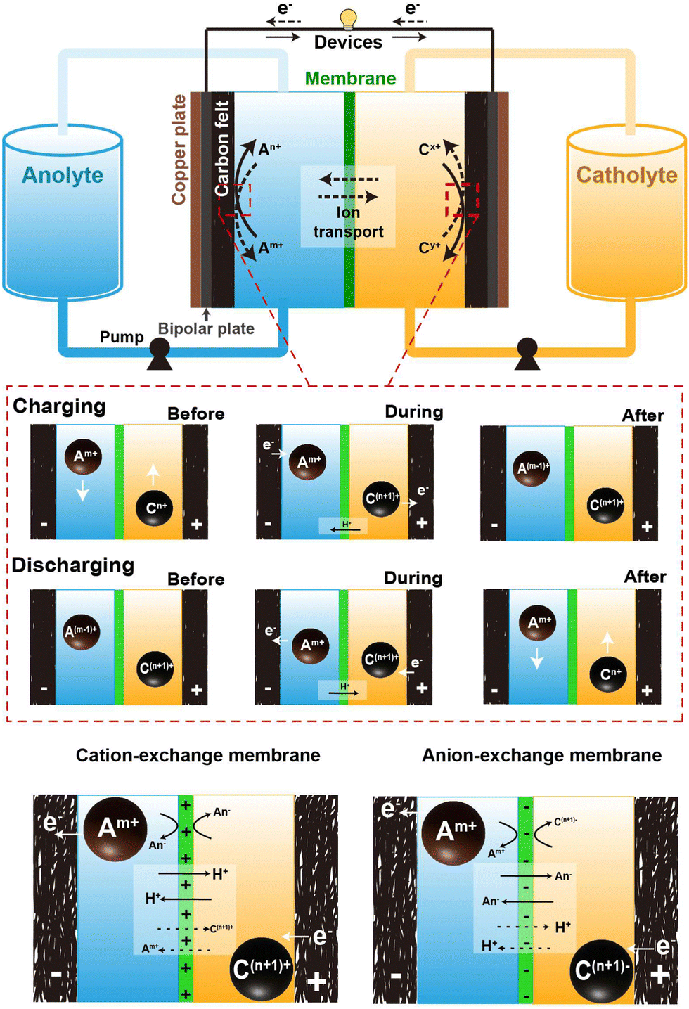 | ||
| Fig. 1 Schematic representation of the components comprising an aqueous redox flow battery, and the operational mechanism throughout the charging and discharging phases. | ||
In the depicted AQRFB, the redox couples are represented by Am+/A(m−1)+ and Cn+/C(n+1)+, where Am+/A(m−1)+ denotes the anolyte and Cn+/C(n+1)+ represents the catholyte. Throughout the charging process, the negative electrolyte undergoes reduction to A(m−1)+, while the positive electrolyte gets oxidized to C(n+1)+. Electrons are transported from the positive side to the negative side through an external circuit, causing the charge carrier ions to diffuse across the membrane in the opposite direction. On the flip side, during the discharge phase, a similar reversible process takes place. In this scenario, the anolyte moves through a permeable electrode, producing electrons as it traverses the external circuit. Fig. 1 provides an understanding of the mechanisms at play prior to, during, subsequent to the charging and discharging processes. The equations for the cationic redox reactions (eqn (1)–(4)) and anionic redox reactions (eqn (6)–(8)) are represented as follows:
| Charging (anode): Am+ + e− → A(m−1)+ | (1) |
| Charging (cathode): Cn+ → C(n+1)+ + e− | (2) |
| Discharging (anode): A(m−1)+ → Am+ + e− | (3) |
| Discharging (cathode): C(n+1)+ + e− → Cn+ | (4) |
| Charging (anode): Am+ + e− → A(m−1)+ | (5) |
| Charging (cathode): Cn− → C(n+1)− + e− | (6) |
| Discharging (anode): A(m−1)+ → Am+ + e− | (7) |
| Discharging (cathode): C(n+1)− + e− → Cn− | (8) |
Fig. 2b provides the redox potential profiles of different redox couples employed in AQRFBs. Each curve in the diagram corresponds to a particular redox couple, comprising two entities in distinct oxidation states. The path followed by each curve depicts the respective reactivity and potential for transitioning between their oxidized and reduced states, accompanied by information regarding the number of electron transfers involved. Despite the undeniable advantages of AQRFBs, their practical application is riddled with challenges that demand careful examination.57
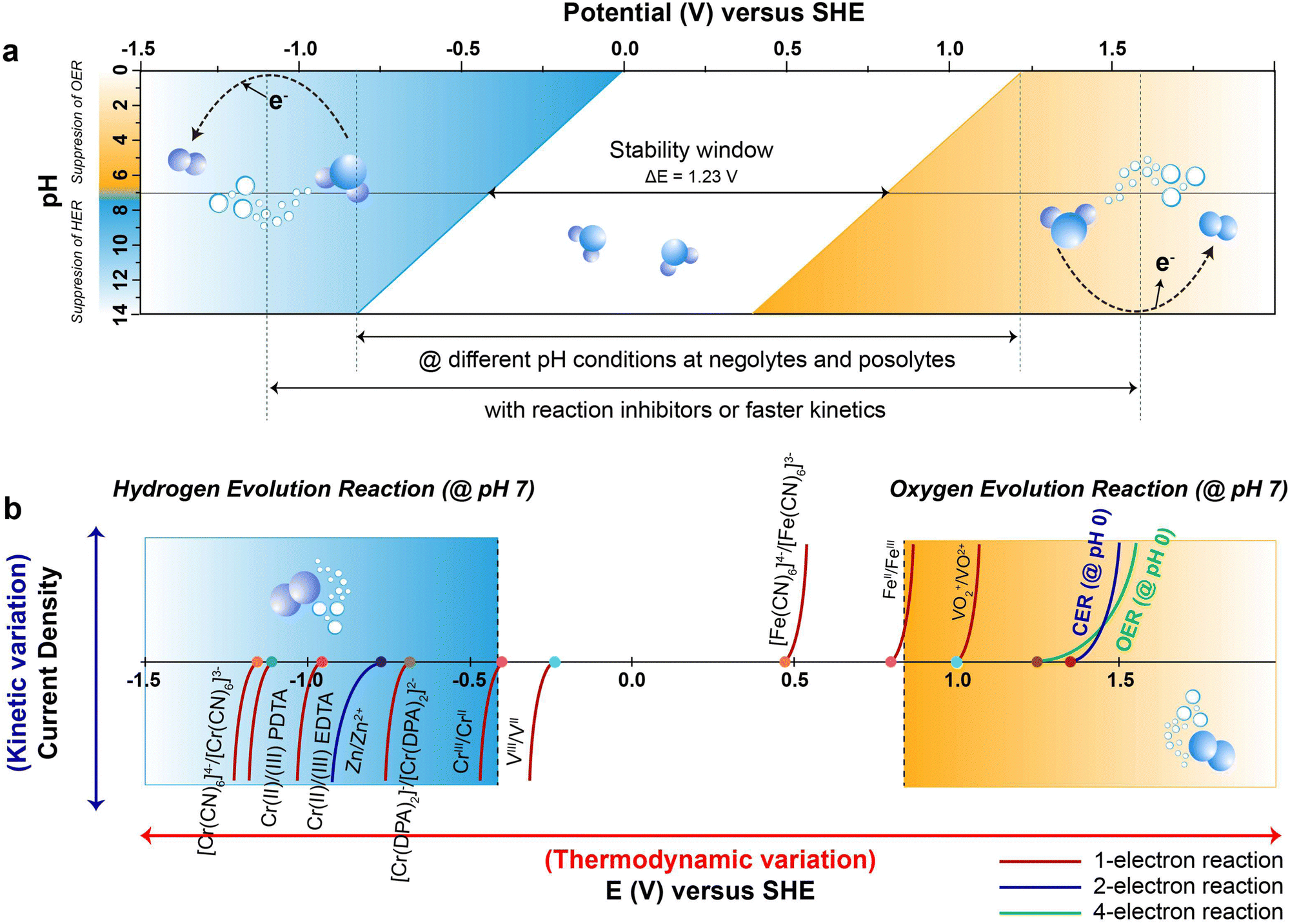 | ||
| Fig. 2 (a) Pourbaix diagram of water depicting potential as a function of pH. The blue and yellow lines represent the lower and higher potential limits of the hydrogen evolution reaction (HER) and oxygen evolution reaction (OER), respectively. Denser blue and yellow gradients indicate the corresponding overpotential regions for the HER and OER. At pH 7, the potential of 1.23 VSHE marks the ESW, where the HER overpotential is notably elevated in an alkaline solution. The expansion of ESW is depicted for the reaction-inhibitor, reaching a maximum of −1.3 VSHE at pH 14 for the HER and 1.7 VSHE at pH 0 for the OER under their respective potential conditions. (b) The figure illustrates the potential for water decomposition, HER/OER overpotential and the redox potential of various reversible redox couples in AQRFBs, illustrating 1 e−, 2 e−, and 4 e− reactions. The curve at 1.36 VSHE represents the chlorine evolution reaction (CER). The x-axis represents electrode potential (E) in volts (V), capturing thermodynamic variations, while the y-axis denotes current density (j) in mA cm−2, reflecting kinetic variations. | ||
One prominent concern is the occurrence of side reactions during charging and discharging cycles. These inevitable electrochemical side reactions significantly hamper the effectiveness, stability and general performance of AQRFBs. Another intriguing factor taken into consideration is cross-contamination. RFBs utilize ion exchange membranes (IEMs) possessing the functional groups of positive or negative ions in the passage channel, allowing the selective transport of non-redox active species such as cations and anions to achieve balanced electrical neutrality. The migration of ions within both a cation-exchange membrane (CEM) and an anion-exchange membrane (AEM) adheres to the principles of the size effect and the Donnan exclusion principle. The size effect dictates that smaller ions tend to move more readily than larger ones.58 On the other hand, the Donnan effect refers to the interaction between the membrane and the electrolyte where charged ions in one electrolyte attract the oppositely charged ions, creating an uneven distribution of ions near the membrane. This principle is crucial for preventing cross-mixing and maintain ion-separation.59 The choice between CEM and AEM significantly influences battery performance. CEMs are most commonly utilized when the redox couple involved are cations (eqn (1)–(4)), which is the case for most AQRFBs (e.g., all-vanadium RFB). AEMs are utilized when the redox couple are anions (eqn (5)–(8)) (e.g., hydrogen–bromine RFB). When a CEM is employed, it selectively allows the movement of positively charged ions (cations) while restricting the passage of negatively charged ions (anions). Conversely, an AEM facilitates the transport of anions, with the exception of the active species involved in the redox reactions.60 There are also chances of allowing cations due to the size effect, which gradually leads to capacity fade. This flexibility allows for the utilization of a broader range of redox couples and enhances the versatility of RFBs. Although CEMs are designed to selectively allow the passage of cations and restrict their counterparts, there are instances of ion transport that deviate from the desired selectivity. This is relevant when dealing with certain ions that might have similar sizes or charge densities.61 These unintended interactions can lead to a degree of cross-contamination between the compartments. However, the performance of AEMs, particularly under high current densities, can encounter limitations due to the kinetics of anion exchange.62 Taking this into consideration, Chen et al.63 suggested that a membrane possessing low permeability towards the active species and high ionic conductivity can withstand high current densities. While AEMs excel in permitting the passage of both ions, the kinetics of anion exchange can be comparatively slower than other ion-exchange processes. Consequently, at elevated current densities, AEMs might struggle to ensure the rapid movement of anions, potentially leading to concentration polarization; this occurs when ions accumulated near the electrode–membrane interfaces, impeding overall electrochemical reactions, and reducing efficiency.64 Therefore, a novel approach has been reported by Wang et al.65 to overcome this issue, which is the development of an amphiphilic membrane where the membrane possesses a combination of both hydrophilic and hydrophobic regions exhibiting controlled permeability. Another approach to minimize the cross-contamination is the utilization of a bipolar membrane where both the CEM and AEM are utilized.66
As the pursuit of sustainable grid-scale energy storage solution intensifies, it becomes crucial to comprehend and address these side reactions in order to unlock the full potential of AQRFBs. In this section, we delve into two primary side reactions responsible for the degradation of the electrochemical performance of AQRFBs.67 The first one is the hydrogen evolution reaction (HER), which takes place at the cathode. The other is the oxygen evolution reaction (OER), occurring at the anode, collectively known as water electrolysis or water splitting or water decomposition, where hydrogen and oxygen gases are produced. Furthermore, the other side reactions such as cross-over of electroactive species between the catholyte and anolyte, lead to capacity losses and reduced Coulombic efficiency.
Potential/voltage limitation due to water
Typically, there are two-half reactions involved in water electrolysis: HER and OER, as depicted in the overall reaction (eqn (9)),68 | (9) |
The minimum thermodynamic potential for water decomposition is 1.23 V, governed by the standard Gibb's free energy (eqn (10)):
| ΔG = −nFE | (10) |
![[thin space (1/6-em)]](https://www.rsc.org/images/entities/char_2009.gif) 485 C mol−1), and E is the electrochemical potential.69 Under standard conditions, the Pourbaix diagram portrays the pH-dependent thermodynamically stable potentials for both the HER and OER. Within the diagram, the blue line and the denser blue gradient in Fig. 2a represents the lower thermodynamic potential and overpotential of the HER, respectively.70 Within the lower range of the voltage window, water is subjected to reduction at the anode, initiating the HER process through a transfer of two electrons occurring between the electrode surface and the adsorbed intermediates of HER. Similarly, the yellow line and the denser yellow gradient in Fig. 2a correspond to the higher thermodynamic potential and overpotential of OER, respectively. At the higher potential of the voltage window, water gets oxidized at the cathode, causing the OER through the transfer of four-electrons, converting hydroxyl ions at the surface of the electrode into oxygen gas.71 This continual gas evolution during the charging can have serious effects, including safety concerns due to the flammability, an increase in internal impedance leading to the mechanical degradation and undesirable Coulombic efficiency (CE) resulting in significant polarization.72
485 C mol−1), and E is the electrochemical potential.69 Under standard conditions, the Pourbaix diagram portrays the pH-dependent thermodynamically stable potentials for both the HER and OER. Within the diagram, the blue line and the denser blue gradient in Fig. 2a represents the lower thermodynamic potential and overpotential of the HER, respectively.70 Within the lower range of the voltage window, water is subjected to reduction at the anode, initiating the HER process through a transfer of two electrons occurring between the electrode surface and the adsorbed intermediates of HER. Similarly, the yellow line and the denser yellow gradient in Fig. 2a correspond to the higher thermodynamic potential and overpotential of OER, respectively. At the higher potential of the voltage window, water gets oxidized at the cathode, causing the OER through the transfer of four-electrons, converting hydroxyl ions at the surface of the electrode into oxygen gas.71 This continual gas evolution during the charging can have serious effects, including safety concerns due to the flammability, an increase in internal impedance leading to the mechanical degradation and undesirable Coulombic efficiency (CE) resulting in significant polarization.72
The ESW of an aqueous electrolyte refers to the difference between the thermodynamic potential of the HER and OER, which remains constant at ∼1.23 VSHE regardless of the electrolyte pH. However, achieving water decomposition requires an additional potential beyond this thermodynamically required value to drive the electrochemical reaction at a desired rate. In simpler terms, a potential >1.23 VSHE is necessary (as shown in Fig. 2a) due to potential losses and slow reaction kinetics associated with water decomposition.73 This additional potential is known as overpotential (η), which is added to the thermodynamically required potential for water decomposition.74 Typically, this overpotential consists of three contributing sources: the electrochemical overpotential (ηA), arising from sluggish kinetics that need to surpass the activation energy barrier for the electrochemical reaction to proceed; the concentration overpotential (ηC) caused by limitations in the transport of reactants and products to and from the electrode surface, resulting in the deposition of reactants; and the ohmic overpotential (ηR), attributed to internal impedance.75 Each of these overpotentials arises form kinetic limitations at different steps of water decomposition.76 The total overpotential can be expressed as the sum of these three sources of overpotential (eqn (11)):77
| ηtotal = ηA + ηC + ηR | (11) |
In the HER and OER process, the electrochemical overpotential corresponds to the energies of the intermediate formed at each step of the reactions. For the HER, Fig. 3a illustrates the electrochemical overpotential of the HER from a thermodynamic standpoint, with the reaction coordinate (x-axis) and Gibb's free adsorption energies of the intermediates (ΔGi) (y-axis). When the overpotential is positive (η < 0), the applied potential (E1) is above the thermodynamically required potential (E0), represented by the blue solid line at the bottom in Fig. 3a, the reaction is uphill and thermodynamically undesirable (ΔG < 0); therefore, the HER does not occur. Similarly, for OER, Fig. 3a illustrates the electrochemical overpotential of the OER. At negative overpotential (η > 0), the applied potential (E1) is below the thermodynamically required potential (E0), represented by the yellow solid line at the top in Fig. 3a; therefore the OER does not occur.78 In contrast, the concentration and ohmic overpotential rely on the morphological properties of the electrodes and electrolytes, such as electrical and ionic conductivity, concentration of salts and pH.75,79
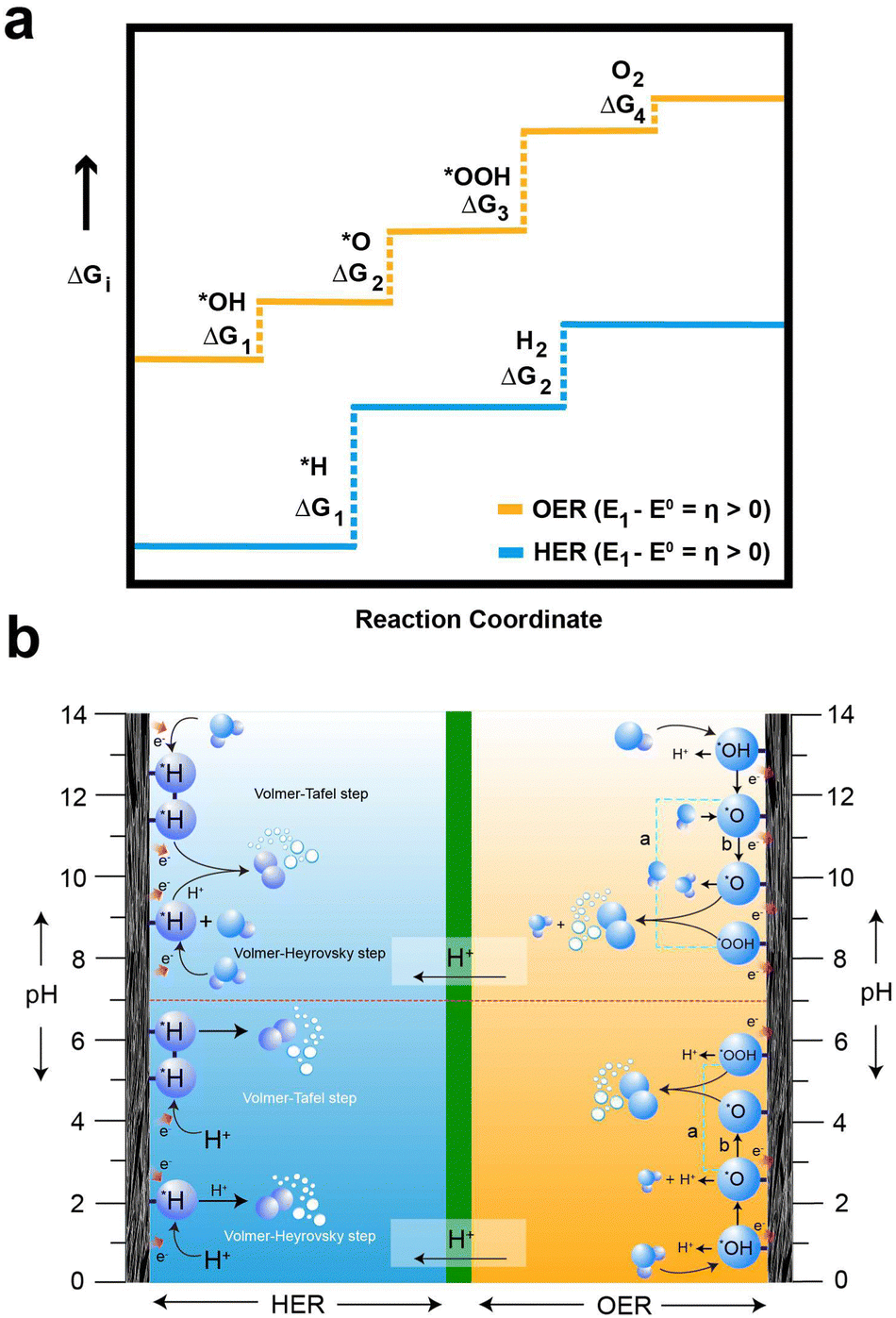 | ||
| Fig. 3 (a) Gibbs free energy variations from water to distinct intermediates during the HER and OER. The blue line corresponds to the HER process, and the yellow line corresponds to the oxygen OER process at potential E1. Reactions at this potential are energetically uphill and thermodynamically unfavorable, leading to the suppression of both HER and OER. (b) Schematic depiction of the HER process at the anolyte, presenting the Volmer–Tafel and Volmer–Heyrovsky steps, alongside the OER process at the catholyte under both acidic and alkaline conditions, according to the pH effects. The species with asterisks (*) denote adsorbed species at the active site on the electrode surfaces. In diagram (a) and (b) on the cathode side, *O combines with *OOH and *O directly combines, respectively. | ||
For the OER in acidic and neutral electrolytes, the OER involves the consumption of water to generate oxygen and protons as products.83 However, in alkaline electrolytes, the reaction consumes OH− to produce oxygen and water. The OER exhibits a higher potential than the HER, due to the four-electron transfer reactions, which inherently result in slow kinetics, as they involve the breaking of O–H bonds and the establishment of bonds between oxygen atoms. Fig. 3b elucidates the intricate series of steps in the OER process, accentuating the complexities inherent in these electrochemical reactions. Furthermore, the OER relationship between the overpotential of OER and the electrolyte pH exhibits limited correlation. The OER mechanism encompasses a more extensive array of intermediates (*OH, *O, and *OOH) compared to the HER process. The series of stepwise reactions for the OER in acidic and alkaline electrolytes is depicted in Fig. 3b. According to the thermodynamic outlook, each step has a theoretical Gibb's free energy of 1.23 eV. The Gibbs free energies of O2, *O, and *OOH are obtained as 4.92 eV, 2.46 eV, and 3.96 eV, respectively. However, the actual values of Gibbs free energy of each step differ from the value due to the influence of binding energy.78 Regardless of the different intermediates formed, the binding energy of the oxygen atom to electrode surface plays a crucial role in the OER process.84 As a result, high electrode energies hinder the formation of *OOH, while low electrode binding energies make it difficult to form *OH, preventing the initiation of the OER process.76
With the growing demand for resilient, robust, and environmentally friendly energy storage technology, researchers and engineers have been exploring a wide range of designs and chemical compositions for electrolyte to enhance AQRFBs for diverse applications. As a result, various types of AQRFBs that have emerged over the years have been discussed below.
Overview of the emergence of AQRFBs
As mentioned earlier, there are various types of AQRFBs and the one extensively studied will be briefly discussed below. The design of the RFB system was initiated around 1970 with the emergence of the Fe–Cr RFB system at NASA.85,86 This system uses an aqueous electrolyte consisting of the Fe2+/Fe3+ redox couple in the catholyte and the Cr2+/Cr3+ redox couple in the anolyte, with hydrochloric acid serving as the supporting electrolyte. The reactions corresponding to the charge transfer in the Fe–Cr system are depicted in Fig. 4a This one-electron transfer reaction simplifies the charge transfer and allows for permissible overpotentials, irrespective of the electrocatalysts. Nevertheless, Fe–Cr RFB suffers from a low open circuit voltage, typically ranging between 0.90–1.20 VSHE, and slow kinetics of the Cr2+/Cr3+ redox couple. In contrast, the Fe2+/Fe3+ redox couple demonstrates remarkable reversibility and efficiency.47 The next system that has emerged is the bromine/polysulfide RFB system, utilizing an electrolyte composed of an aqueous solution containing sodium bromide as the catholyte and sodium polysulfide as the anolyte. This system benefits from having abundant, cost-effective, and highly soluble redox-active species, reducing the amount of electrolyte required to accommodate a certain amount of charge. Because the redox-active species are anions, this system employs a cation-exchange membrane (CEM). Fig. 4b visually depicts the movement of charges at the electrode, as well as the transfer of Na+ (charge carrier) across the membrane. However, this system is prone to electrolyte cross-over and mixing, leading to the formation of hydrogen sulfide and bromine gas.87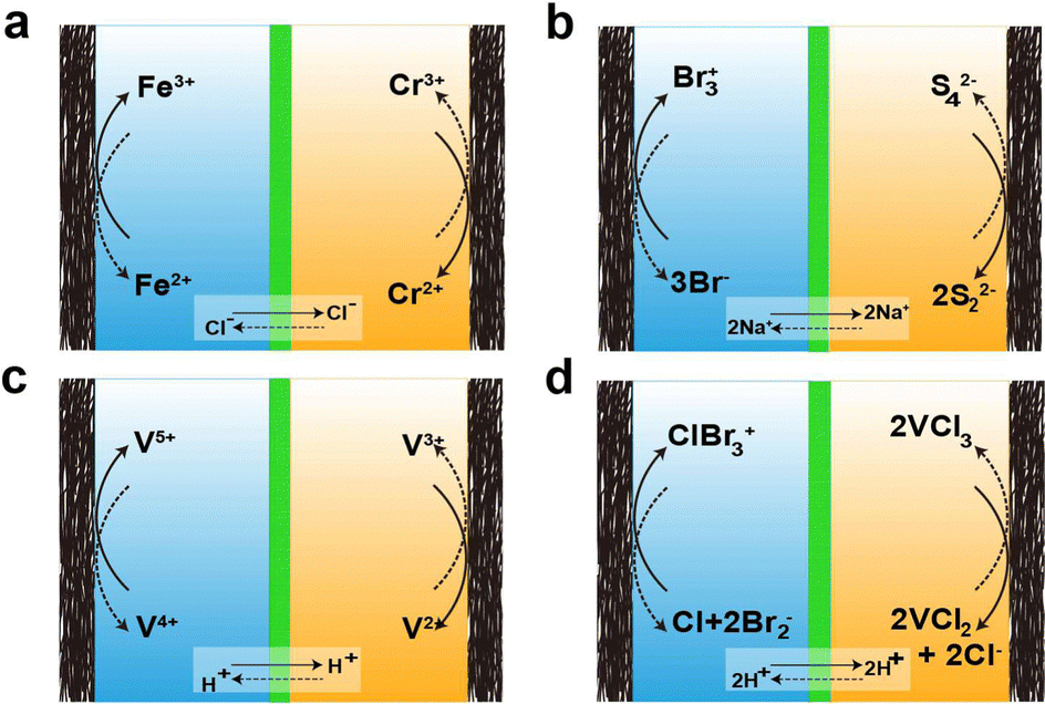 | ||
| Fig. 4 Schematic depiction of charge transfer mechanism in different aqueous redox flow batteries: (a) iron–chromium RFB [1.23 V], (b) bromine–polysulfide RFB [1.5 V], (c) all-vanadium RFB [1.23 V], and (d) vanadium–bromine RFB [1.1 V] (the values in paratheses indicate the redox couple potential). | ||
The main issue with the previously mentioned systems is the lach of compatibility between the two electrolytes and their vulnerability to contamination by each other. This cross-contamination leads to efficiency loss during respective electrochemical performance cycles and deterioration in the capacity of the overall performance, necessitating extravagant electrolyte separation and active species recovery. To address this, the design of all-vanadium RFBs was introduced, employing a minimum of four oxidation states of vanadium, which allows cross-over to only cause efficiency loss while enabling the retrieval of the other electrolyte. In this system, anolyte utilizes the V2+/V3+ redox couple, and catholyte utilizes the V4+/V5+ redox couple.88–96 The reactions for the transfer of charges at the electrode and the ion cross-over are depicted in Fig. 4c. Unfortunately, the energy density of the VRFB system (approximately 35 W h L−1) is affected by solubility.97 However, the inclusion of halide ions increases the solubility, resulting in higher energy density (around 70 W h L−1), leading to the emergence of the vanadium/bromine system. Fig. 4d represents the reaction of charge transfer during the charge and discharge cycles. Nonetheless, this system resulted in bromine vapor exhausts during operation. To overcome this issue, bromine-complexing agents are employed. Another classification of RFBs is the hybrid redox flow batteries (HRFBs), featuring the deposition of metal during battery operation, such as zinc/bromine98 and zinc/chlorine systems.99
Aqueous redox mediators
In light of the preceding discussion, it is evident that solubility and concentration pose utmost significance in determining the energy density and cell voltage of the RFB system.100 To overcome the solubility barrier, using an electrolyte slurry with a range of 10–40 M has been considered as a viable option.101 Nevertheless, this approach necessitates a substantial quantity of conductive additives, which subsequently results in increased viscosity. An alternative approach that has garnered considerable attention in resolving this issue is the incorporation of redox mediators in the electrolyte, acting as electron carriers. These redox mediators (RMs) are solid redox-active materials that serve as an “electronic shuttle” between the electrode and the active materials, enabling solid reactants to participate in the reaction without coming in direct contact with the electrode.102 Introducing redox mediators in AQRFBs adds a new dimension to their electrochemical behaviour, offering several potential advantages. The use of RMs can significantly enhance the kinetics of electrode reactions, reducing the overpotential losses, and ultimately improving the overall efficiency. By mediating the electron transfer, these compounds effectively mitigate the charge transfer resistance, facilitating swift and more efficient electrochemical reactions. Furthermore, RMs extend the range of available redox couples, increasing the energy density and capacity of the AQRFB. This expanded redox capability not only enhances the energy storage potential but also enables tailoring the performance of the battery to specific applications and operational requirements. The presence of RMs helps to mitigate the impact of side reactions and undesirable cross-over of electroactive species between the anode and cathode compartments. By controlling electron mediation through these compounds, a higher level of selectivity is achieved, suppressing undesired chemical reactions and contributing to improved stability and cycle life.103 RMs undergo reversible reduction and oxidation processes during electrochemical cycles, making them capable of reviving a depleted metallic anode. Criteria for a better performing RMs include a suitable redox potential, spontaneity for electron transfer, fast kinetics, high solubility, and greater stability. In aqueous batteries, RMs can be categorized into (a) inorganic RMs (e.g., Fe3+/Fe2+, Cu2+/Cu+, Br2−/Br−, I2−/I−, etc.,), (b) organic RMs (e.g., quinone derivatives, viologen derivatives, etc.,), and (c) organometallic compounds (e.g., metallocene derivatives).100,104,105For instance, Lei et al.106 demonstrated satisfactory performance for a Zn–Mn aqueous battery designed for high-areal-capacity applications. They employed iodide (I−) as a RM, which reduces the solid MnO2 deposited on the carbon felt into soluble Mn+ ions by self-oxidizing into I3−, thereby reducing the formation of inactive MnO2 during the battery cycling. Accordingly, the Coulombic efficiency and cell capacity were appreciably increased. The rejuvenation of an inactive metal is because the accumulated oxidized redox mediator gradually moves back to the anode. As a result of this migration, the inactive metal undergoes spontaneous breakdown, facilitating the charge/discharge of the metallic source back into the cathode.107–111 Zhang et al.112 demonstrated a redox targeting process in VRFBs by using the surface-immobilized Prussian blue (PB) and Prussian blue analogues (PBA) at the cathode and anode, respectively. The application of PB and PBA to the electrode surface effectively mitigated the evolution of oxygen and hydrogen, respectively, while simultaneously enhancing the redox kinetics and reversibility of the redox couple. Similarly, Cheng et al.113 enhanced the kinetics of VO2+/VO2+ by using PBA granules as a redox mediator in the VRFB catholyte. During charging and discharging, charges were stored in PBA in a reversible manner via a redox targeting process between (VO)6[Fe(CN)6]3 and the redox couple VO2+/VO2+ (with the same Nernstian potential). By utilizing PBA as a capacity booster, the redox-targeted VRFB attained a capacity density of 44.6 A h L−1 at the catholyte. In a recent study, Huang et al.114 explored the utilization of a phenazine derivative known as (7,8-didrocyphenazine-2-sulfonic acid, (DHPS)) as a redox mediator in the anolyte of alkaline zinc-based redox flow batteries. The researchers found that the redox targeting reaction between DHPS and the inactive zinc led to a substantial enhancement in the cycling stability of the DHPS-mediated zinc electrode, enabling the achievement of a large-areal capacity.
Potential unleashed: conquering side reactions
Approach based on volcano plots
The efficacy of the reaction-inhibitor involved in water electrolysis is governed by the adsorption energy of the catalyst towards various HER/OER intermediates.115,116 In accordance with the Sabatier principle,117 volcano plots demonstrating the activity and selectivity of various catalysts are showcased in Fig. 5a and b. The have typically been utilized as a potent tool for developing the catalyst in an extensive spectrum of electrocatalytic processes. During water electrolysis, catalysts closer to the apex of the volcano plots display optimal adsorption energy for the HER/OER intermediates, consistently show enhanced activity. Conversely, catalysts positioned on the left and right sides of the volcano plot with high and low adsorption energies for the HER/OER intermediates, respectively, display impeded activity.118,119 Consequently, selecting a catalyst from the bottom of the volcano plot that possesses extremely high and extremely low binding energy with the HER/OER intermediates is one of the effective strategies. If the binding energy is excessively high, the product dissociation does not occur, whereas if it is excessively low, the catalyst does not bind, therefore preventing any reaction from taking place.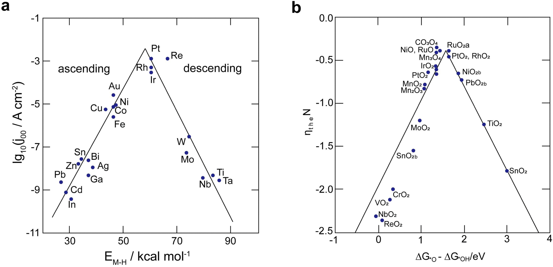 | ||
| Fig. 5 (a) Catalyst activity for the HER in an acidic solution presented as a volcano plot, depicting the connection between hydride formation energy (EM–H) and current density (j00). (b) Volcano plot showcasing the activity of catalysts for OER, displaying overpotential in relation to the standard free energies of various metal oxides. | ||
Over the years, Bi has been extensively employed as an electrocatalyst material for HER suppression and to augment the redox kinetics and reversibility of the anolyte. Liu et al.120 revealed that the suppression of HER is attributed to the sequential rise in the HER overpotential. Li et al.121 studied the performance of graphite felt (GF) decorated with Bi ions (Fig. 6a), which enhanced the redox kinetics of V2+/V3+ in VRFBs. Cyclic voltammetry (CV) results validated the redox kinetics behaviour of the Bi-deposited anode. Fig. 6b depicts the redox reaction both before and after the introduction of Bi ions. It demonstrates the differentiation in peaks of the V3+/V2+ redox couple, emphasizing the deterioration of electrochemical performance within the anolyte of the VRFB, whereas the electrodeposition of Bi ions on the negative electrode prior to the reduction of V3+/V2+ enhances the redox kinetics of the reaction at the anode, as indicated by the decrease in the value of peak separation of the V3+/V2+ redox couple (Fig. 6b). Subsequently, Yang et al.122 investigated the catalytic effect of Bi on V4+/V5+ and V3+/V2+ redox couples in VRFBs. The results quantified that the V4+/V5+ redox couple has negligible exposure to the catalytic effect exhibited by Bi ions. This is because Bi oxidized irreversibly to Bi3+ (Fig. 6c inset) during the initial cycle of the charging process at the cathode. The Bi3+/Bi redox couple has a lower standard redox potential (0.308 VSHE) than the V4+/V5+ redox couple, which explains the lack of a catalytic effect of Bi3+ on the catholyte redox couple. On the other hand, the CV curves of the 2 wt% Bi-loaded carbon felt (CF) exhibited the highest oxidative peak current compared to the CF without Bi, confirming that Bi enhances the redox kinetics of the active species at the anolyte. The energy efficiency (EE) of this system was measured to be 79% at a current density of 160 mA cm−2, which was higher than that of the system without Bi incorporation (Fig. 6d). Furthermore, Suarez et al.123 proposed that the formation of an intermediate, BiHx, acts as a hinderance to the unintended irreversible evolution of hydrogen, as more hydrogen atoms bind with Bi, leaving fewer H+ ions available for the formation of hydrogen gas.
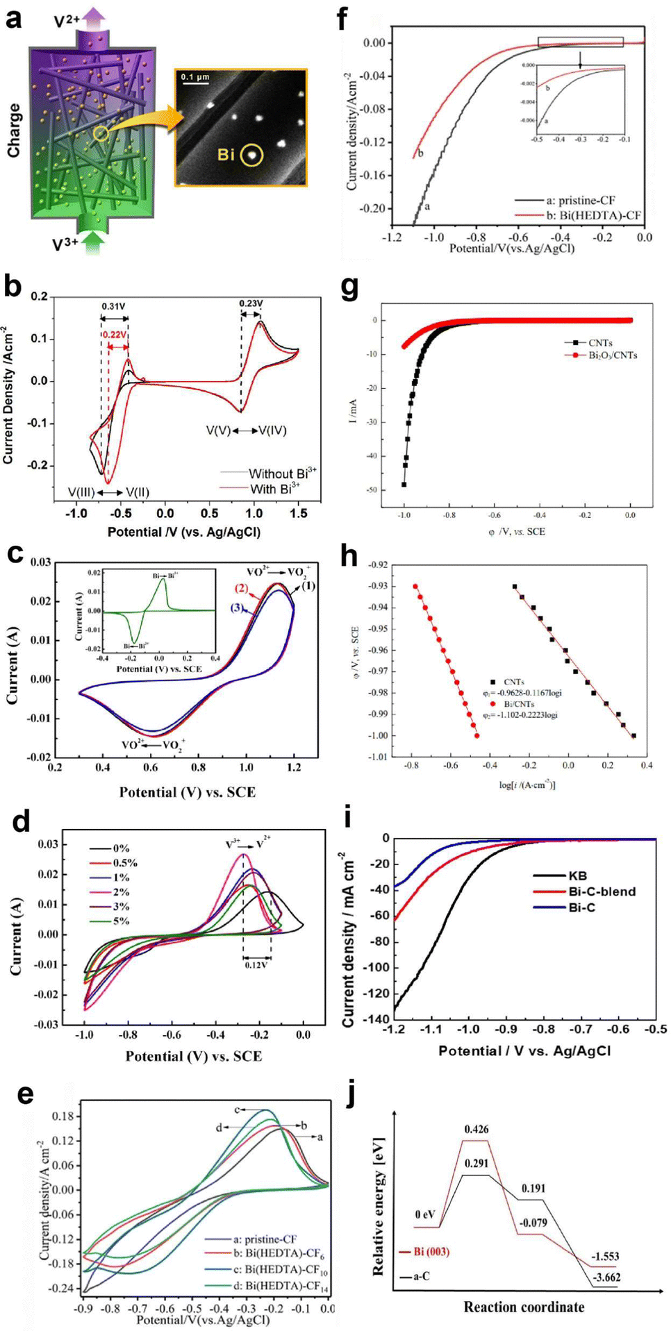 | ||
| Fig. 6 (a) Depiction of Bi-loaded graphite felt utilization in VRFBs. (b) Cyclic voltammetry (CV) profiles on a glassy carbon electrode within 2 M VOSO4 + 5 M HCl electrolytes, with and without 0.01 M BiCl3. Reproduced with permission from ref. 98. Copyright 2013 American Chemical Society. (c) CV curves: curves 1 and 2 corresponds to 0% and 2% Bi-loaded CF in 0.05 M VO2+ + 0.05 M VO2+ + 3 M H2SO4 solution, respectively; and curve 3 corresponds to the 0% Bi-CF in the same solution. (d) CV curves of x-Bi-CF (x = 0%, 0.5%, 1%, 3%, 5%) in 0.05 M V3+ + 0.05 M V2+ + 3 M H2SO4 solution are presented. Reproduced with permission from ref. 99. Copyright 2017 Elsevier. (e) CV profiles of pristine-CF and Bi(HEDTA)-CFs acquired in a 3 mol L−1 V3+ + 3 mol L−1 H2SO4 solution. (f) LSV curves of pristine and Bi(HEDTA)-CF10 tested in a 1 mol L−1 H2SO4 solution at a scan rate of 2 mV s−1. Reproduced with permission from ref. 101. Copyright 2019 Springer. (g) and (h) LSV curves and Tafel plots for bare carbon nanotubes (CNTs) and Bi2O3 electrodes assessed in a 3 mol L−1 H2SO4 solution with a scan rate of 1 mV s−1. Reproduced with permission from ref. 102. Copyright 2020 ESG. (i) LSV curves of Ketjenblack (KB), Bi–C blend, and aC surfaces. (j) Density functional theory (DFT) generated free energy diagrams depicting associative HER pathways on Bi(003) and aC surfaces. Reproduced with permission from ref. 40. Copyright 2023 Elsevier. | ||
Following this, Liu et al.124 reported that the use of Bi–EDTA complex modified CF, known as Bi(HEDTA)-CF10, as an anode for suppressing the HER and enhancing the redox activity of the redox species at the anolyte in VRFBs. The CV curves (Fig. 6e) show that Bi(HEDTA)-CF10 has the lowest peak potential, indicating that Bi enhances the redox activity of V3+/V2+. In addition, the linear sweep voltammetry (LSV) curve (Fig. 6f) depicts that the evolution of hydrogen is less prominent at Bi(HEDTA)-CF10 compared to pristine CF, implying that the presence of Bi effectively limits the HER occurrence. Similarly, Chu et al.125 reported the use of Bi2O3 carbon nanotube (CNT)-modified GF as an anode in VRFBs and studied the behaviour of HER inhibition from the LSV curves depicted in Fig. 6g. The HER potential of Bi2O3/CNT modified GF is −1.102 V, indicating a significant reduction in the HER compared to unmodified GF. Fig. 6h shows the Tafel plot showing a linear relationship between the potential and logarithm of current density. Recently, Wen et al.126 investigated the influence of Bi concentration on hydrogen evolution and vanadium redox kinetics using in situ mass spectroscopy, revealing that the absence of Bi ions leads to greater hydrogen evolution during cycling and that Bi insertion shifts the HER to a more negative range, compared to electrolytes without Bi ions, enhancing the vanadium redox kinetics and suppressing the HER during cell operation.
In addition to these findings, Bi has also been employed as a bifunctional catalyst in Fe–Cr RFBs to suppress the HER and to enhance the redox reaction of the Cr2+/Cr3+ redox couple at the anode. Ahn et al.46 synthesized and employed Bi nanoparticles embedded in Ketjenblack (KB) carbon (Bi-KB) as an HER reaction-inhibitor and enhancer of the redox kinetics of the Cr2+/Cr3+ redox couple. The LSV curves show that bare KB has an onset potential of −0.943 V, while the Bi-KB exhibits −1.042 V, indicating the HER inhibition behaviour of the Bi-KB reaction inhibitor (Fig. 6i). Density functional theory (DFT) calculations revealed that the adsorption energy of Bi on hydrogen (−2.98 eV) is higher than that of amorphous carbon (aC), suggesting that the Bi surface exhibits a higher binding energy towards the HER intermediates and a higher energy barrier for the evolution of hydrogen gas compared to aC, making Bi as an inhibitor for the HER process (Fig. 6j).
Recently, Xie et al.127 demonstrated the HER suppression behaviour in Fe–Cr RFB using a bimetallic reaction-inhibitor, Pb/Bi. Chronoamperometric analysis showed a drastic reduction in the current for hydrogen evolution for the bimetallic reaction-inhibitor with the highest Pb ratio (−0.2 A) compared to pristine CF (−0.45 A) at −0.2 V, confirming the ability of Pb to suppress the HER (Fig. 7a). Furthermore, the CV results (Fig. 7b) demonstrated a significant enhancement in the reversibility of the Cr2+/Cr3+ redox couple for the reaction-inhibitor with higher Bi content compared to pristine CF, validating the redox kinetics enhancing behaviour of Bi. The optimized bimetallic reaction-inhibitor containing 25% Pb–75% Bi@CF showed considerably better electrochemical performance with higher CE and EE compared to pristine CF (Fig. 7c). DFT calculations further supported the experimental results since the adsorption energy of chromium on Bi (−6.99 eV) was higher than the adsorption energy of carbon (−2.19 eV) (Fig. 7c). The intensified hybridization of Cr-3d and Bi-3p orbitals demonstrated by the partial density of state (PDOS) indicates the effective redox active kinetics of Cr2+/Cr3+ on the Bi surface (Fig. 7c).
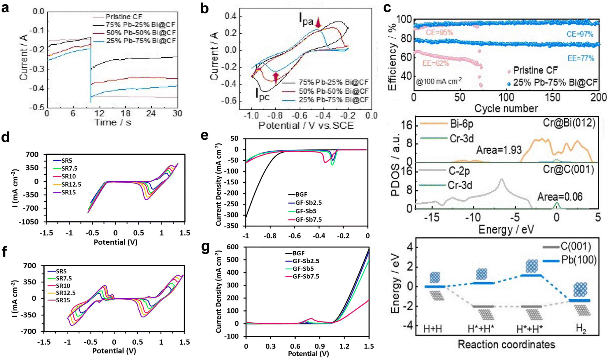 | ||
| Fig. 7 (a) Chronoamperometric analysis conducted on various CF samples. (b) CV curves depicting different compositions of Pb and Bi on CF samples. (c) The first plot represents a comparison of cycle life at 100 mA cm−2, the second plot illustrates the partial density of states of Cr on Bi(012) and Cr(001), and the third plot displays the associative energy barrier for the HER on Pb(100) and Cr(001). Reproduced with permission from ref. 104. Copyright 2023 Elsevier. (d) CV curves recorded at different scan rates for bare graphite felt (GF). (f) GF with 2.5 wt% Sb. LSV curves obtained for bare GF and various Sb concentration in a 1.5 M H2SO4 + 3 M HCl solution (e) at the negative side and (g) at the positive side. Reproduced with permission from ref. 105. Copyright 2022 Elsevier. | ||
Antimony (Sb) is another widely used metal as a reaction-inhibitor for HER suppression and to enhance the redox kinetics at the anode in AQRFBs. Loghavi et al.128 investigated the electrocatalytic behaviour of Sb-incorporated GF in the VRFB system. The bare GF (BGF) showed no anodic redox due to the severe evolution of hydrogen (Fig. 7d). Rather, Sb-GF showed well-defined redox peaks of vanadium redox couples at different scan rates (Fig. 7f). Furthermore, the LSV curve on the positive and negative side revealed that the presence of a reaction-inhibitor increases the overpotential of the HER and OER occurring on the anodic (Fig. 7e) and cathodic sides (Fig. 7g) of the VRFB, respectively. Apart from these discussed metals, there are several other metals recognized for the suppression of HER such as Ti, W, Nd, and Nb.129–136
Furthermore, Sun et al.137 conducted quantitative studies to assess the rate of HER on various carbon paper materials employed as the anode in VRFBs. The results demonstrated that the evolution of hydrogen on the carbon surface is inevitable, and the rate of HER is determined by the electrochemical surface area (ESCA) value, which is also responsible for capacity fading in VRFBs. GF embedded with TiN (titanium nitride) and nanostructured Ti3C2TxMXene (C – carbides, T – oxygen, fluorine, and hydroxyl groups) showed an enhanced ECSA.138,139 Schweiss et al.140 also investigated the parasitic HER on different carbon electrodes with varying graphite content, and the results revealed that carbon fibres with high graphite content exhibited lower HER during the charging process, while the one with a high amorphous content exhibited higher HER.
The OER process takes place on the cathode side of AQRFBs during the cycling of battery, leading to the deterioration of electrochemical performance. Therefore, to suppress the OER, typically the reaction-inhibitor should exhibit excessively high or low binding energy towards OER intermediates such as *OH, *O, and *OOH. Based on the volcano plot (Fig. 5b), especially metal oxides such as PbO2, MnO2, NbO2, CoO, MoO2, and TaO2 provide high overpotential for the OER; thus, they act as reaction-inhibitors for the OER.133,135,141–145 As a majority of these electrodes are made using thermal techniques, it has been demonstrated that one effective method to lessen OER is to increase the preparation temperature of the metal oxide electrode. To date, there are only fewer reports available for the investigation of OER in AQRFBs.
Approach based on solvation shells
Solvation shells refer to the arrangement of solvent molecules around a solute particle, such as an ion or a molecule, in a solution. This arrangement of solvent molecules forms a solvation shell or hydration shell, depending on whether the solvent is water or another solvent, respectively. The solvation shell is dynamic and can influence various physicochemical properties of the solution, such as solubility, conductivity, and viscosity. Suppressing water electrolysis refers to minimizing or preventing the decomposition of water into hydrogen and oxygen gases through an approach based on trapping free water molecules in the solvation shell by applying certain strategies such as increasing the concentration of salts, and inclusion of electrolyte additives.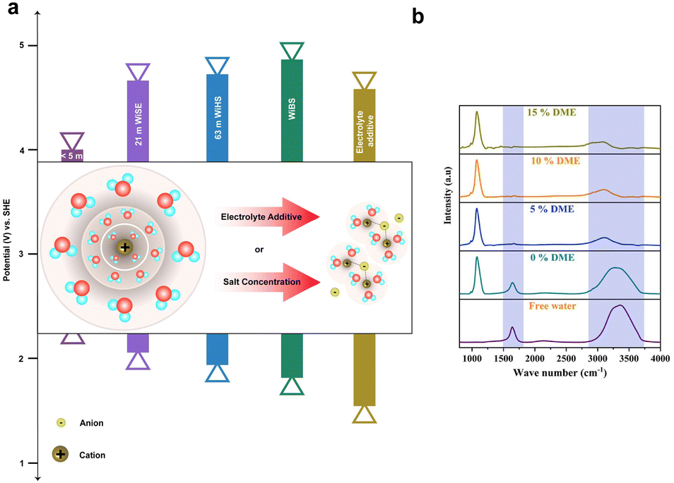 | ||
| Fig. 8 (a) Depiction of the extension in the ESW attributed to varying salt concentrations, such as <5 M (salt-in-water), 21 M WiSE (LiTFSI), 63 M WiBE (21 M LiTFSI + 7 M LiOTf), Wish (42 M LiTFSI + 21 M Me3EtN·TFSI), and the incorporation of an electrolyte additive (2 M LiTFSI-94% PEGDME450-6% H2O). The inset of the figure illustrates the solvation shell (for low salt concentration) with primary and secondary hydration shells, demonstrating the entrapment of water in the primary hydration shell through increased salt concentration or inclusion of an electrolyte additive (bonding between the anion and central cation corresponds to the interaction with the anion, while the absence of bonding indicates the free anion). (b) FTIR spectra for WiBE featuring different additive compositions (DME), showcasing peak shifts. | ||
The strategy of WiSE has been extended by dissolving a secondary salt in a parent hydrate salt to obtain a “water-in-bisalt” electrolyte (WiBE). For instance, 21 M LiTFSI/7 M LiOTf is prepared by dissolving lithium trifluoromethane sulfonate (LiOTf) in LiTFSI(H2O)2.6. The prepared molten electrolyte has a water/cation ratio of 2:1, consisting of 28 M Li+. The remarkable high ionic density of the electrolyte suppresses the HER. This electrolyte design eventually widens the ESW (from 1.83 to 4.9 VLi+/Li) and reduces the free water activity.158 Another significant way to reduce free water activity was proposed by Yamada et al.159 By combining the hydrate melts of Li salts, Li(TFSI)0.7(BETI)0.3·2H2O at room-temperature with the eutectic composition, which has a cation/water ratio of 2:1, the hydrogen bonding between two water molecules is effectively reduced, resulting in their separation. As a result, the bulk water molecules present in the primary solvation shell of Li+ correspond to the widened ESW between 1.23 and 5.05 VLi+/Li. Similarly, the monohydrate of Li salts with the eutectic composition melts at room-temperature, Li(PTFSI)0.6(TFSI)0.4·1H2O, resulting in widening the ESW (∼5 V) due to the presence of the asymmetric anion PTFSI,enabling the liquidus range of hydrates. This Li-salt monohydrate also leads to the suppression of hydrogen evolution.160
The thermodynamic stability of water can be increased by adding organic solvents with a high Gutmann donor number (DN), i.e., high electron-donating capacity, as a co-solvent in the aqueous electrolyte. Recently, Wang et al.163 reported that the use of DMSO as a co-solvent in aqueous Al-ion batteries enhances the thermodynamic stability of water by forming strong intermolecular hydrogen bonds with water. This improves bond strength of O–H in water molecules, resulting in a high overpotential for the HER and a minimal evolution of hydrogen, about 0.02 ml min−1 cm−2.
As discussed earlier, the water-in-bisalt electrolyte suppresses free water activity and widens the ESW. Furthermore, the addition of additives rich in hydrogen bonds enhances the electrochemical performance of aqueous batteries and results in the suppression of hydrogen. Hwang et al.164 have investigated this by using 4 M ZnSO4 + 2 M Li2SO4 as the WiBE and 1,2-dimethoxyethane (DME) as the additive rich in hydrogen bonds. Fig. 8b represents the FTIR spectra for WiBEs with different composition of additives, where the increase in DME composition shifts the O–H peaks from a larger to a smaller wavenumber. This shift occurs because the free water is restrained by the weak hydrogen bonding. Typically, the addition of 10% (DME) increases the interaction between zinc ions (Zn2+) and sulfate, forming a hydrogen bond between the free water and DME solvent. Therefore, the water-in-bisalt enriches the Zn2+ ions, while DME screens the formation of free water, steering the ions to the anode. This corresponds to the reduction of free water activity and helps suppress the hydrogen evolution reaction.
Approach based on chelating or strong-field ligands
Chelation of redox species alters their redox potential, resulting in the suppression of HER and widening of the ESW of water in AQRFBs.165,166 In recent research, attempts have been made to employ tris-bipyridine chromium complexes ([CR(bpy)2(H2O2)]3−),167 acetylacetonate chromium and vanadium complexes ([Cr(acac)3], [V(acac)3]).168 However, these complexes often dissolve or decompose on reduction in aqueous electrolyte. Some of the complexes, namely, the iminodiacetate chromium complex ([Cr(IDA)2]−)169 and picolinic acid chromium complex ([Cr(PIC)2]−),170 have very low reduction potential and lack adequate affinity to bind with Cr2+ (Fig. 9a). Ruan et al.171 designed a chromium complex with different chelating ligands for the Fe–Cr RFB and revealed that the molecular design of a complex structure provides a viable solution for combating the HER. They developed a chromium complex with rapid kinetics, the dipicolinic acid complex, [Cr(DPA)2]−. Although it exhibits better kinetics and has a substantial size that prevents the cross-over, it suffers from limited solubility. Therefore, to increase the solubility, a derivative with a dipotassium salt and an ammonium functional group has been crafted, namely, the [Cr(f-DPA)2]+Br− (3-((2,6-bis(ethoxycarbonyl)pyridine-4-yl)oxy)-N,N,N-trimethyl propan-1-aminium bromide) chromium complex. The solubility was increased from 0.4 M to 0.71 M. This enhancement in solubility is due to the repulsion and hindrance effect of the hanging ammonium functional groups, limiting the contact between molecules and preventing the onset of solid formation. This complex has been paired with Fe(CN)64− to form a neutral Fe–Cr RFB. The potentials were shifted to the negative side but not beyond the SHE, thus triggering the onset of hydrogen evolution.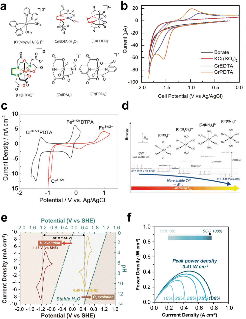 | ||
| Fig. 9 (a) Molecular structures of various chromium complexes engineered for the mitigation of HER, encompassing [Cr(bipy)2(H2O)2]3−, Cr(EDTA)(H2O), [Cr(PDTA)]−, [Fe(DTPA)]2−, [Cr(IDA)2]−, and [Cr(DPA)2]−. (b) CV curves of 0.125 M KBi (black), non-complex 5 mM Cr(III)sulfate (red), 5 mM Cr-EDTA (blue), and 5 mM Cr-PDTA (yellow) within a 0.125 M KBi electrolyte. Reproduced with permission from ref. 145. Copyright 2019 Elsevier Inc. (c) CV curves of 50 mM Cr-PDTA/Fe-DTPA (black) in a 0.25 M KBi solution and 50 mM CrCl3/FeCl2 in 3 M HCl conducted on a glassy carbon electrode. Reproduced with permission from ref. 39. Copyright 2019 American Chemical Society. (d) Jahn–Teller effects illustrated with d-orbital splitting of the Cr(II) octahedral complex and their corresponding reduction potential. (e) CV curves of [Cr(CN)6]2−/3− redox species and the corresponding [Fe(CN)6]4−/3−, where the blue dashed line indicates the thermodynamic reduction potential of the HER and OER. (f) Power density plotted against current density at different states of charge (SOC) (0%, 25%, 50%, 75%, and 100%). Reproduced with permission from ref. 167. Copyright 2023 John Wiley. | ||
As a result, the aminopolycarboxylate (APC) chelates were taken into consideration for complexation. Some APC chelated complexes such as the 1,2-diaminocyclohexane iron complex (Fe-CyDTA), ethylenediamine tetra-acetic acid iron complex, and N-hydroxy ethylethylenediamine triacetic acid (Fe-HEDTA), coordinate with water and undergo dimerization. For instance, the chelation of chromium with ethylenediamine tetra-acetic acid (Cr-EDTA) shifted the redox potential of Cr3+/Cr2+ from −0.41 VSHE to −0.99 VSHE, but the coordination with water triggered a significant hydrogen evolution. Therefore, the former ligand was replaced with a larger ligand, refraining the coordination of water. As a result, the chelation of chromium with 1,2-propylenediamine tetra-acetic acid (Cr-PDTA) shifted the redox potential to −1.10 VSHE, which is beyond the reduction potential of Cr-EDTA (Fig. 9b). This complex aided in the inhibition of hydrogen evolution and showed performances of 515 mW cm−1 without the need for any catalyst. This has been validated by the fact that PDTA, when chelated with chromium ions, forms an octahedral structure in the electrolyte and expels the H2O from the foremost coordination sphere. It is noteworthy that the use of Cr-PDTA as a chelated complex has allowed the achievement of a high-voltage chromium-bromine AQRFB (>2 V).172 This approach has also been extended to vanadium RFBs, where diethylene triamine penta-acetate (with a 7-coordinate geometry) was used as the chelating agent. The chelated redox couple V[(DPTA)]2−/3− showed a low redox potential of −1.0 VAg/AgCl (pH 9) and suppressed the evolution of hydrogen.173 Similarly, a Fe–Cr RFB was exemplified using the iron complex (Fe-DTPA) and chromium complex (Cr-PDTA) (Fig. 9c), demonstrating greater electrochemical reversibility than the non-chelated complexes. This greater reversibility of redox kinetics suggests that no significant side reactions take place.45
More recently, Jang et al.174 reported a novel Fe–Cr RFB framework by employing the strong field cyanide ligand (CN−) to diminish the impact of Jahn–Teller175 distortion and enhance the operating voltage with trivial hydrogen evolution. The reported novel electrolyte, K3[Cr(CN)6], exhibited a lower redox potential of −1.15 VSHE, retaining the stability against the HER and suppressing cross-over effects owing to the bulk size of [Cr(CN)6]4−, which coupled with a strong field π-acceptor ligand (CN−) possesses vacant orbitals that interact with the d orbitals of the metal, leading to the stabilization of t2g orbitals. The DFT calculation confirmed that the shift in the redox potential to more negative values was indeed influenced by the presence of the strong field cyanide ligand, which effectively enhances rapid redox kinetics. DFT calculations demonstrated that the strong field cyanide ligand boosts the swift kinetics, as evidenced by the ease of the redox reaction, aided by weak Jahn–Teller effects (Fig. 9d). The half-cell CV data (Fig. 9e) depict the possibility of achieving a high potential of 1.64 VSHE. The full cell had been configured, and the capacity degradation was determined to be >0.02% per cycle, indicating the absence of adverse side reactions (HER). The material also exhibited a maximum peak power density of 0.41 W cm−2, signifying its suitability as a promising candidate for large-scale ESS applications (Fig. 9f).
Approach based on the Pourbaix diagram and near-neutral pH
According to the Pourbaix diagram (Fig. 2a), the overpotential for the HER is significantly higher in an alkaline solution compared to an acidic solution. On the other hand, the overpotential for the OER is higher in an acidic solution than in an alkaline solution. Thus, employing an alkaline medium as the electrolyte in the anolyte and an acidic medium as the catholyte can widen the ESW of H2O beyond the typical value of 1.23 VSHE.176,177 In the design of RFBs, incorporating an alkaline electrolyte in the anolyte and an acidic electrolyte in the catholyte, can effectively suppresses the HER and OER, respectively, as mentioned earlier. Yu et al.178 demonstrated a Zn–Br RFB that remarkably exhibited an expanded ESW of 3.0 V with an enhanced operating voltage of 2.1 V. In this case, the alkaline electrolyte significantly reduced the HER potential to −1.3 VSHE at pH 14, while enhancing the OER potential to 1.7 VSHE at pH 0. However, to maintain the electrolyte pH on both sides, it is necessary to mitigate the neutralization between the acidic catholyte and alkaline anolyte. Therefore, a design involves three electrolytes and two membranes (AEM‖CEM), where the middle electrolyte (i.e., neutral electrolyte) can be adopted to decouple the electrolyte pH and suppress the acid–base neutralization. Gong et al.179 reported a high voltage Zn–Fe RFB with a standard operating voltage of 1.99 V. The anolyte contained Zn(OH)42−/Zn as the redox couple with NaOH serving as the supporting electrolyte, while the catholyte contained Fe3+/Fe2+ as the redox couple, with HCl serving as the supporting electrolyte. This RFB system utilizes both AEM and CEM, with a middle electrolyte of NaCl separating the two membranes. This setup allowed ion movement between the AEM and CEM while preventing direct contact between the membranes, thereby potentially suppressing chemical cross-over by isolating the acidic and alkaline electrolytes. The alkaline electrolyte reduced the HER potential to −0.83 VSHE at pH 14, while the acidic electrolyte maintained the OER potential at 1.23 VSHE at pH 0. This RFB system achieved ESW of 2.06 V. The widening of the ESW in accordance with different pH conditions of the negolyte and posolyte, attributed to the side reaction-inhibitor, is depicted in Fig. 2a.The change in the electrolyte pH can broaden the ESW, but it can also affect other critical factors such as the solubility of active species, kinetics of electrode processes (both favourable and unfavourable), cell stability and durability.180 AQRFBs are currently being developed using various redox chemistries, including organic and coordination complexes. Additionally, near-neutral pH electrolytes are deployed to improve the stability of the active species and enable the use of a wider range of materials to suppress the HER/OER.181,182 Schroder et al.183 reported a near-neutral pH all-iron RFB that utilizes an iron-based coordinated redox couple, Na[FeIII-racEDDHA]/Na4[Fe(CN)6]. The stability of the complex in an aqueous solution remains intact within a pH range of 5 to 1, allowing for the use of low-cost cell elements. The designed RFB exhibited a cell voltage of 843 mV at a SOC of 50% in a pH range of 8.6. Similarly, Ruan et al.171 demonstrated a Fe–Cr RFB in a neural pH range using complexation chemistry of chromium ([Cr(DPA)2]−). The flow cell results revealed the efficacy of complexation in reducing the hydrolysing tendency of the metal-ion at neutral pH. Therefore, we emphasize that AQRFBs operating at a near-neutral pH efficiently suppress the HER/OER. This characteristic permits the utilization of less corrosion-resistant materials and cost-effective membranes in cell design, leading to reduction in the installation costs. However, the development of suitable redox couples that can effectively operate in a neutral-pH electrolyte is still an active area of research.
Kinetic vs. thermodynamic stability
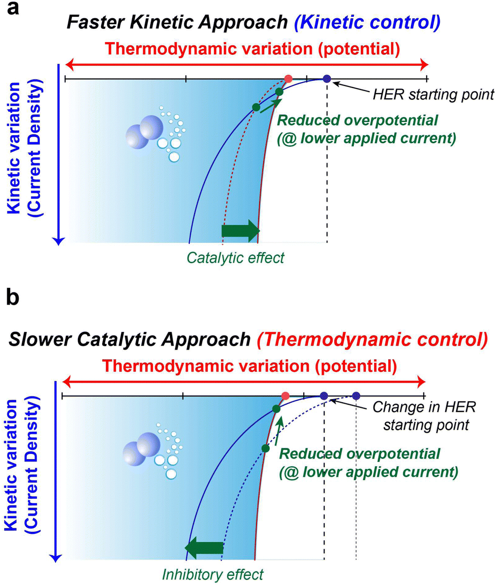
The preceding discussions encompass the strategies available to suppress parasitic side reactions such as the HER, and OER, which incessantly lead to the degradation of electrochemical performance in AQRFBs. The emphasis on HER suppression outweighs that of the OER, as the HER necessitates only half the number of electrons for its occurrence. Additionally, the HER demonstrates a more distinct potential difference when compared to most suitable anode materials, whereas the OER showcases a potential proximity to various cathode possibilities. Nevertheless, it is important to note that the HER also triggers anode corrosion and reduces the shelf-life of the RFB system.The strategies at hand can be categorized into two distinct aspects, i.e., kinetics and thermodynamic strategies. These concepts address different facets of the reaction and can be leveraged to manage or minimize water electrolysis in different ways. Fig. 10a visually presents the concept of kinetic control that offers a swift kinetic approach. In this approach, the introduction of a reaction-inhibitor instead of the conventional metal catalyst for the HER results in distinctive interaction with the associated intermediates. These interactions could manifest as a rapid chemical reaction or the formation of stable complexes. This swift interaction either consumes the intermediates before they engage in the HER or generates stable species that do not evolve into hydrogen gas. These species might be trapped or immobilized within the reaction medium. Because of this rapid interaction between the reaction-inhibitor and the intermediate (e.g., BiHx), fewer intermediates are available to participate in the HER.123 This leads to the implementation of kinetic control, where the introduction of the reaction-inhibitor paves a faster kinetic pathway, as depicted in Fig. 10a. This pathway diverts the intermediates away from the HER, thus maintaining an overall reaction control at the kinetic level. Consequently, the primary objective of kinetic suppression is to decrease the rate of undesired electrochemical reactions (e.g., HER and OER). Therefore, the judicious selection of a suitable reaction-inhibitor based on the volcano plot, with lower binding energy towards the HER and OER, effectively suppresses the reaction. Moreover, these reaction-inhibitors exhibit a synergistic effect, enhancing the kinetics of redox couples by providing active sites for the reactions. Similarly, modifying the catalyst or electrode surface to obstruct the active sites for the intermediates can also modify the catalytic activity concerning the HER and OER.184
 | ||
| Fig. 10 (a) Schematic representation of kinetic control on the HER with a faster kinetic approach posing the catalytic effect. (b) Schematic representation of thermodynamic control on the HER with a slower catalytic approach posing the inhibitor effect. | ||
Conversely, Fig. 10b illustrates the concept of thermodynamic control which involves a more gradual catalytic approach that focuses on suppression by regulating the driving forces of the electrolysis reaction at a thermodynamic level. Alterations in the solvation structure and the incorporation of the electrolyte additive to strengthen O–H bonds are approaches that impede the reaction kinetics, causing the reaction to progress at a slower rate compared to the highly active catalysts. These approaches introduce an additional challenge in the form of increased HER overpotential (more negative), resulting in an inhibitory effect. This shift in the HER onset potential towards a more negative value deviates from the original HER onset potential. By shifting the potential to a more negative value during reduced current density, an elevated overpotential becomes necessary to facilitate the reaction at a slower pace. The combination of the slower catalytic approach with the inhibitor effects renders the overall reaction to be less thermodynamically favourable. Analysing the interactions between the chemical environment and the strength of O–H bonds within water molecules is crucial for achieving thermodynamic control. Water, with its covalent bonds, can have its O–H bond strength to render water molecules inert, preventing their interaction with electrons and hindering the formation of intermediates for HER and OER. Another intriguing avenue for thermodynamic suppression involves widening the ESW. This can be achieved by adjusting the salt concentration through electrode potential modification, introducing redox mediators to control the redox environment, and altering the solvation structure. Examining the Pourbaix diagram of water provides insights into modifying system operating conditions. Raising the overpotential of water electrolysis (at high or low pH) suppresses the thermodynamic driving force. The utilization of both alkaline and acidic electrolytes with IEMs for ion transport, as facilitated by the Pourbaix diagram, expands the ESW. Gaining insights into the solvation structure that alters or encases free water molecules is another crucial aspect, achievable by introducing additives into the electrolyte. Taking into account all these tactics, the overarching thermodynamic strategy aims to enhance the O–H bond strength in H2O molecules, while the kinetic strategy entails raising the overpotential for HER and OER reactions.
Future perspectives
The future of AQRFBs relies on the successful mitigation of side reactions. To tackle these obstacles, we have deliberated various perspective strategies from distinct angles to boost the effectiveness of reaction-inhibitors and diminish the side reactions. These methods are based on the kinetic and thermodynamic perspectives. Within our proposed framework, we cover the creation of redox mediators, reaction-inhibitors, functional electrolyte additives, and design of ligands. By prioritizing the inhibition of theses unfavourable chemical reactions, our objective is to elevate battery stability, enhance energy efficiency, and prolong the longevity of AQRFBs.Design of redox mediators
In light of the concerns discussed in the context of RMs, we emphasize the importance of designing and selecting a redox mediator with a redox potential closely aligned with the redox couple of the anolyte and catholyte. This technique shows promise in boosting the redox kinetics of the redox couples. Additionally, we highlight the intriguing potential of adapting an appropriate redox mediator with a redox potential very close to the potential range of water decomposition (HER/OER potential) to limit the HER/OER in AQRFBs. On the catholyte side of AQRFBs, using an RM that exhibits a redox reaction near or slightly more positive than the OER potential can effectively mitigate the oxygen evolution process; as illustrated in Fig. 11a, the redox reaction of the RM competes with the OER process. Similarly, on the anolyte side, employing a a redox mediator with a potential near or slightly more negative than the HER potential holds substantial promise for suppressing the HER. Fig. 11a illustrates this concept, where the redox reaction of the chosen RM interacts favourably with the HER potential, effectively suppressing the evolution of hydrogen.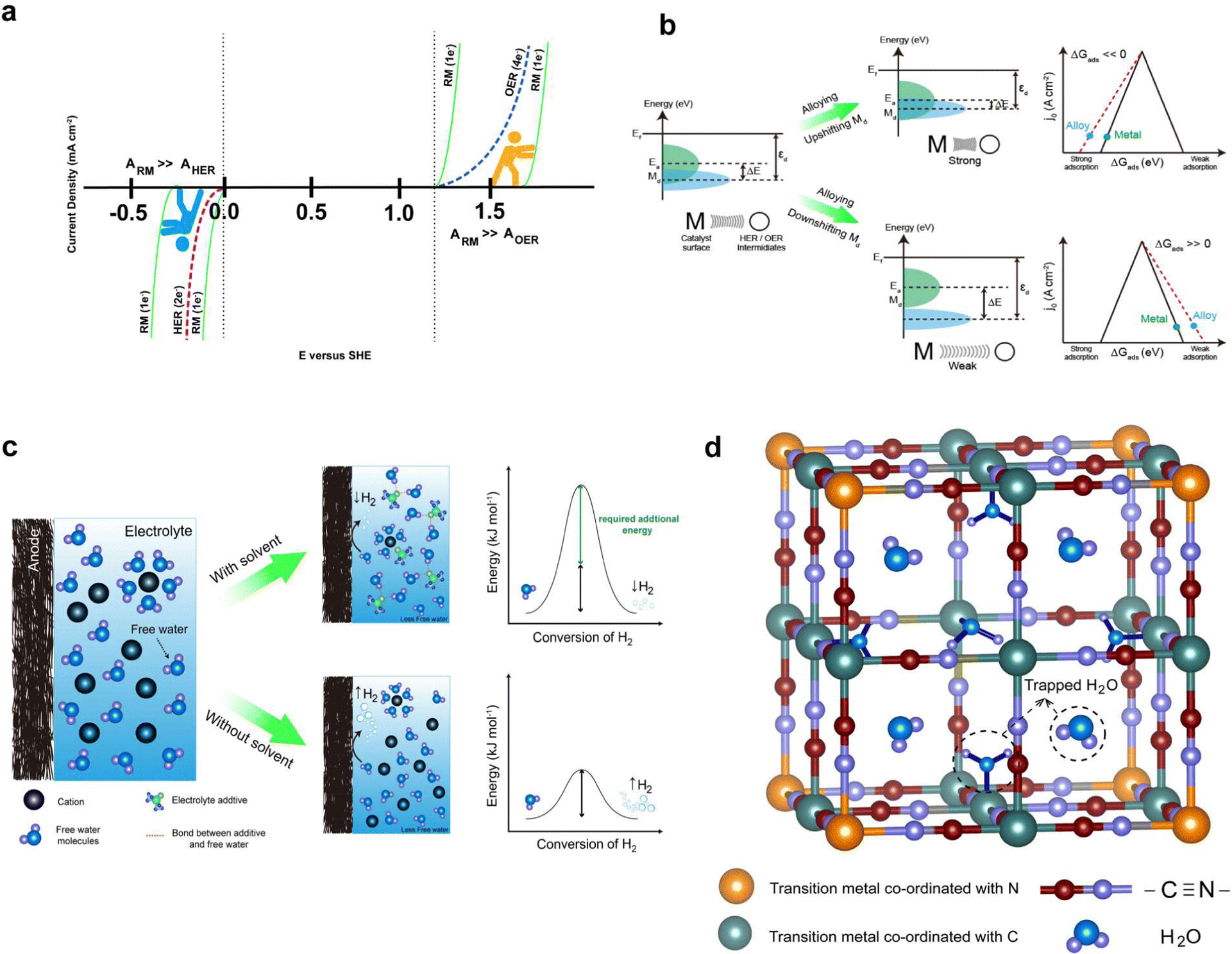 | ||
| Fig. 11 (a) Schematic illustration displaying the competitive activity of RM (one-electron transfer (ARM) in comparison with AHER and AOER). RM exhibits a rapid one-electron transfer reaction, outpacing both HER and OER activities, regardless of their slightly more negative and more positive potentials, respectively. (b) Schematic representation showcasing the tuning of catalyst adsorption energies, transforming them into “reaction-inhibitors” through the upshifting (top) and downshifting (bottom) of d-orbitals. (c) Schematic depiction of solvation structure modification, which diminishes the presence of free water through the integration of an electrolyte additive (top), requiring higher additional energy for hydrogen gas release. (d) Illustration portraying PBA as a trapping agent for free water molecules, denotes as AxP[R(CN)6]·nH2O (where P represents the transition metal coordinating with C, R signifies the transition metal coordinating with N, and A represents the mobile cation, which is represented by larger spaces with H2O in the figure). | ||
Moreover, maximizing the cell voltage is an efficient technique for enhancing the power and energy density of AQRFBs. To achieve this, it is important to select an anolyte and catholyte with the greatest difference in redox potential while still staying within the ESW of water.100 However, the narrow ESW of H2O severely limits the deployment of high-potential redox couples, as they often exhibit a redox reaction at or over the OER limit, resulting in limited electrochemical reactions due to high charging potential. To address this constraint, we propose the use of RM chemistry that remains stable within the ESW of H2O. This approach allows for initiation of the redox reaction of the RM and facilitates the charging process. By implementing this novel design of RM chemistry, the redox kinetics of high potential redox couples can be carried out within the ESW of H2O, effectively suppressing the evolution of gases throughout the charging process.
Design of reaction-inhibitor beyond the volcano plot
The analysis of the outcomes discussed under the approach based on volcano plot reveals that the d-band centre of the catalysts plays a vital role in the interaction between the surface of the catalyst and the adsorbed species such as *H and *OH. By adjusting the d-band centre of the catalyst, it is possible to fine-tune the binding strength of the adsorbed species at active sites, thereby influencing the overall catalytic property of the material. An ideal catalyst demonstrates a d-band centre (Md) that is in close proximity to the Fermi energy level (Ef) and exhibits a minimized energy gap between Md and the energy level of the adsorbate (Ea). Significantly, when a catalyst is alloyed with a metal possessing either lower or higher electronegativity compared to the parent catalyst, it leads to the creation of an electron-deficient or electron-abundant region near to the alloyed metal, respectively. The electron-donating or accepting nature of the alloying metal induces the changes to the density of state (DOS) near the Fermi energy level of the catalyst, shifting the d-band centre of the catalyst closer to or farther away from the Fermi energy level. Consequently, the shift influences the binding energy between the surface of the catalyst and HER/OER intermediates.185,186A significant upshift of Md (Fig. 11b) results in stronger adsorption (ΔGads ≪ 0) between the catalyst and adsorbed intermediates, thereby limiting the desorption step and reducing the activity of HER/OER intermediates. Similarly, a substantial downshift of Md leads to weaker adsorption (ΔGads ≫ 0) between the catalyst and adsorbed intermediates, subsequently decreasing the catalytic activity of the catalyst. Hence, it is conceivable to achieve a better reaction-inhibitor design for water electrolysis by adjusting the adsorption energies of the catalyst with he HER/OER intermediates through alloying with different metals. As depicted in Fig. 10b, this approach can further strengthen or weaken the binding energies of the HER/OER intermediates, effectively controlling the process of water electrolysis.
The critical factor for achieving optimal performance in AQRFBs is the effective loading of reaction-inhibitors for the HER and OER, coupled with the establishment of strong binding forces with the electrode surface. Insufficient contact may result in cross-contamination within the flow cell area, compromising the intended inhibitory effects or acting as inactive species. Furthermore, the amount of loaded reaction-inhibitor also influences the reaction rate, where higher loading can mask the reaction sites for the redox reaction. These refinements are imperative to maintain and maximize the efficacy of the HER/OER inhibition strategy.
Design of multifunctional electrolyte additives
The water electrolysis in AQRFBs can be reduced by designing multifunctional electrolyte additives that suppress free water activity and improve the redox kinetics of the redox couples. The most efficient technique to suppress the water electrolysis in AQRFBs is to limit the hydrogen bonding network of H2O molecules, which, in turn reduces the proton activity via Grotthuss diffusion or the proton hopping mechanism.187 The solvent molecules with strong electron-donating ability, such as DMSO, DME, and DMAC can be utilized as co-solvents with water to suppress the free water activity in AQRFBs. By utilizing solvent additives that function as hydrogen-bond acceptors, the hydroxyl group of H2O form strong hydrogen bonding interactions with the electron-donor group of additives, effectively tethering the water molecules and eliminating the presence of free water molecules. Significantly, the hydrogen bonding interaction between the additive and H2O is stronger than that among the water molecules, thereby raising the energy barrier of H2O decomposition (Fig. 11c) and impeding the water electrolysis. Despite the proven effectiveness of solvation structure design in other types of batteries, its application in the context of AQRFBs remains unexplored. As a result, we emphasize that employing an aqueous-organic hybrid solvent in AQRFBs can inhibit water electrolysis.In addition to the proposed strategy, we assert that Prussian blue analogues (PBA) can be employed to reduce the activity of free water molecules by trapping them in their crystal structure. The standard formula for PBA (metal–organic framework) is AxMy[B(CN)6]z·mH2O, where A represents the alkaline metal, B represents the transition metal, and x, y, z, m represents the stochiometric values. PBA features an internal three-dimensional network with broad ionic channels (3.2 Å diameter) and interstices (4.6 Å diameter).188,189 The large interstitial positions in the open structure of PBAs are suitable for accommodating various cations (e.g., Na+, K+, Rb+, Cs+, etc.,) as well as water molecules.190–193Fig. 11d depicts the visualization of PBA as a host structure supporting the concept. Hence, incorporating PBA as an electrolyte additive in AQRFBs can effectively diminish the reactivity of free water molecules, HER/OER intermediates, and mitigate water electrolysis by trapping free H2O within the open framework structure of the host.
Addressing and controlling the viscosity of the electrolyte solution poses a significant challenge, particularly when incorporating electrolyte additives and highly concentrated electrolytes. The increased viscosity of the solution poses obstacles in achieving optimal voltage efficiency, leading to a reduction in the flow rate and consequently diminishing the Coulombic efficiency. Moreover, the highly acidic and basic nature of the electrolyte additive introduces an additional layer of complexity, as it triggers corrosion reaction that may potentially causing damage to internal cell components. Fine-tuning is essential to enhance overall performance, long-term durability and reliability.194,195
Design of ligand reaction-inhibitors
The modification of electrodes through the integration of specifically tailored ligands marks a novel stride towards curbing the HER and elevating battery performance. As the performance of RFBs relies on efficient electrode kinetics and selective reaction-inhibitor, the integration of tailored ligands onto the electrode surface, which serve as the surface ligands, presents a strategic design approach. This modification can be initiated by depositing transition metal phosphides80,196–201 (often referred to as HER catalysts) on the electrode, followed by the removal of the parent surface ligand. Subsequently, re-ligating with X-type carboxylates (anionic ligand) with a long carbon chain offers a greater HER overpotential. The anionic nature of the carboxylates establishes a strong binding energy with the transition metal phosphide, resulting in a higher ligand density.202,203 Additionally, the increase in length provides the necessary steric hindrance to inhibit the intermediate binding. This impedes the availability of active species for the formation of the necessary intermediate in the Volmer step of the HER process. This modification provides the electrode with an environment that reduces the HER by limiting the surface exposure of active sites on the electrode surface instead of poisoning the active sites.By implementing the ligand-driven modifications, these electrodes can be fine-tuned to steer the electrochemical processes away from the HER, leading to heightened redox reaction efficiencies and overall battery performance. As we venture into the uncharted territory of ligand-mediated electrode modification for RFBs, we not only unveil a potent strategy for optimizing energy storage but also underscore the pivotal role of molecular design in shaping the future of sustainable energy technologies.
Outlook
In conclusion, AQRFBs stand at the forefront of promising energy storage technologies, offering unparalleled benefits in scalability, cost-effectiveness, and long cycle towards sustainable and renewable energy solutions. However, the journey towards realizing their full potential is not without challenges, and the impact of side reactions emerges as a critical consideration. Our perspective review has emphasized the importance of comprehensively addressing the gas-evolving side reaction to overcome kinetic and thermodynamic limitations and fully unleash the potential of AQRFBs. However, the success of AQRFBs hinges on our ability to mitigate the impact of side reactions that can compromise their efficiency and performance over time. Addressing this reaction requires a nuanced understanding of the underlying mechanism and a proactive approach to develop strategies that enhance the stability and longevity of AQRFBs systems. As discussed earlier, electrolyte modification is not only confined to altering the solvation structure, but it is broadened to the introduction of a novel aqueous based ionic liquid electrolyte, representing another facet of the solution. It possesses tunable physicochemical properties, allowing for the customization of electrolytes to meet the specific requirements such as a widened ESW.We also emphasize that a multidisciplinary approach, including the integration of computational modelling, emerges as an invaluable companion. It serves as a predictive framework, enabling researchers to assess the thermodynamic limitations stemming from the side reactions. Beyond the context of electrodes and electrolyte modification, the flow rate at which concentrated redox electrolyte flows also significantly influences gas evolution. Higher flow rates can enhance the mass transport, ensuring a continuous supply of reactants to the electrode surface. Conversely, lower flow rates may lead to the localized depletion of reactants, impacting the kinetics and occupancy of the active site of the electrode during cycling conditions. In such cases, machine learning algorithms and real-time monitoring of electrolyte flow rates, emerge as formidable tools to suppress or mitigate gas evolution.
Continuously refining and implementing these strategies, as researchers push the boundaries of innovation, this integrative framework not only holds the key to suppressing the HER and OER but also opens new vistas for sustainable and efficient energy storage solutions. It heralds a future where RFBs seamlessly integrate with renewable energy sources, contributing significantly to the global pursuit of a clean energy revolution.
Author contributions
V. M., S. J., and H.-W. L. designed this idea and wrote the entire manuscript.Conflicts of interest
There are no conflicts to declare.Acknowledgements
This work was financially supported by the 2023 Research Fund (1.230040.01) of UNIST and the National Research Foundation of Korea (grant no. RS-2023-00208929).References
- Time for lithium-ion alternatives, Nat. Energy, 2022, 7, 461 DOI:10.1038/s41560-022-01073-y.
- C. P. Grey and D. S. Hall, Nat. Commun., 2020, 11, 3577 CrossRef PubMed
.
- J. T. Frith, M. J. Lacey and U. Ulissi, Nat. Commun., 1655, 2023, 14 Search PubMed
- A. Manthiram, X. W. Yu and S. F. Wang, Nat. Rev. Mater., 2017, 2, 161203 CrossRef
- F. Duffner, N. Kronemeyer, J. Tubke, J. Leker, M. Winter and R. Schmuch, Nat. Energy, 2021, 6, 123–134 CrossRef CAS
- K. Liu, Y. Y. Liu, D. C. Lin, A. Pei and Y. Cui, Sci. Adv., 2018, 4, 9280 Search PubMed
- D. M. Davies, M. G. Verde, O. Mnyshenko, Y. R. Chen, R. Rajeev, Y. S. Meng and G. Elliott, Nat. Energy, 2018, 4, 42–50 CrossRef
- B. Dunn, H. Kamath and J. M. Tarascon, Science, 2011, 334, 928–935 CrossRef CAS PubMed
- J. W. Choi and D. Aurbach, Nat. Rev. Mater., 2016, 1, 16013 CrossRef CAS
- M. R. Lukatskaya, B. Dunn and Y. Gogotsi, Nat. Commun., 2016, 7, 12647 CrossRef PubMed
- Lithium-ion batteries need to be greener and more ethical, Nature, 2021, 595, 7 DOI:10.1038/d41586-021-01735-z.
- A. Weidenkaff, R. Wagner-Wenz and A. Veziridis, Nat. Rev. Mater., 2021, 6, 462–463 CrossRef
- R. F. Service, Science, 2014, 344, 352–354 CrossRef CAS PubMed
- M. L. Perry, Science, 2015, 349, 1452 CrossRef CAS PubMed
- B. Hu and T. L. Liu, Science, 2021, 372, 788–789 CrossRef CAS PubMed
- D. L. Chao, W. H. Zhou, F. X. Xie, C. Ye, H. Li, M. Jaroniec and S. Z. Qiao, Sci. Adv., 2020, 6, 4098 CrossRef PubMed
- L. Y. Zhang, R. Z. Feng, W. Wang and G. H. Yip, Nat. Rev. Chem., 2022, 6, 524–543 CrossRef PubMed
- Y. X. Yao, J. F. Lei, Y. Shi, F. Ai and Y. C. Lu, Nat. Energy, 2021, 6, 582–588 CrossRef
- F. Ai, Z. Y. Wang, N. C. Lai, Q. L. Zou, Z. J. Liang and Y. C. Lu, Nat. Energy, 2022, 7, 417–426 CrossRef CAS
- S. O. Tung, S. L. Fisher, N. A. Kotov and L. T. Thompson, Nat. Commun., 2018, 9, 4193 CrossRef PubMed
- S. Q. Huang, H. Zhang, M. Salla, J. H. Zhuang, Y. F. Zhi, X. Wang and Q. Wang, Nat. Commun., 2022, 13, 4746 CrossRef CAS PubMed
- B. Huskinson, M. P. Marshak, C. Suh, S. Er, M. R. Gerhardt, C. J. Galvin, X. D. Chen, A. Aspuru-Guzik, R. G. Gordon and M. J. Aziz, Nature, 2014, 505, 195–198 CrossRef CAS PubMed
- M. Park, J. Ryu, W. Wang and J. Cho, Nat. Rev. Mater., 2017, 2, 16080 CrossRef CAS
- T. Puleston, M. Serra and R. Costa-Castelló, App. Energy, 2023, 355, 122271 CrossRef
- R. Z. Feng, X. Zhang, V. Murugesan, A. Holias, Y. Chen, Y. Y. Shao, E. Walter, N. P. N. Wellala, L. T. Yan, K. M. Rosso and W. Wang, Science, 2021, 372, 836–841 CrossRef CAS PubMed
- M. Nourani, C. R. Dennison, X. F. Jin, F. Q. Liu and E. Agar, J. Electrochem. Soc., 2019, 166, A3844–A3851 CrossRef CAS
- C. C. Ye, A. Q. Wang, C. Breakwell, R. Tan, C. G. Bezzu, E. Hunter-Sellars, D. R. Williams, N. P. Brandon, P. A. A. Klusener, A. R. Kucernak, K. E. Jelfs, N. B. McKeown and Q. L. Song, Nat. Commun., 2022, 13, 3184 CrossRef CAS PubMed
- Z. G. Yang, J. L. Zhang, M. C. W. Kintner-Meyer, X. C. Lu, D. W. Choi, J. P. Lemmon and J. Liu, Chem. Rev., 2011, 111, 3577–3613 CrossRef CAS PubMed
- W. Wang, Q. T. Luo, B. Li, X. L. Wei, L. Y. Li and Z. G. Yang, Adv. Funct. Mater., 2013, 23, 970–986 CrossRef CAS
- M. Skyllas-Kazacos, M. H. Chakrabarti, S. A. Hajimolana, F. S. Mjalli and M. Saleem, J. Electrochem. Soc., 2011, 158, R55–R79 CrossRef CAS
- C. P. de Leon, A. Frias-Ferrer, J. Gonzalez-Garcia, D. A. Szanto and F. C. Walsh, J. Power Sources, 2006, 160, 716–732 CrossRef
- X. F. Li, H. M. Zhang, Z. S. Mai, H. Z. Zhang and I. Vankelecom, Energy Environ. Sci., 2011, 4, 1147–1160 RSC
- A. Choi, Y. Y. Song, J. Kim, D. Kim, M. H. Kim, S. W. Lee, D. H. Seo and H. W. Lee, Adv. Mater., 2023, 2303199 CrossRef CAS PubMed
- S. Jayasubramaniyan, C. Lee and H. W. Lee, J. Mater. Res., 2022, 37, 4017–4034 CrossRef CAS
- J.-E. Jang, S. Jayasubramaniyan, S. W. Lee and H.-W. Lee, ACS Energy Lett., 2023, 8, 3702–3709 CrossRef CAS
- H. T. Zhou, H. M. Zhang, P. Zhao and B. L. Yi, Electrochim. Acta, 2006, 51, 6304–6312 CrossRef CAS
- M. Skyllas-Kazacos and F. Grossmith, J. Electrochem. Soc., 1987, 134, 2950–2953 CrossRef CAS
- J. Shin, C. Kim, B. Jeong, N. Vaz and H. Ju, J. Power Sources, 2022, 526, 231144 CrossRef CAS
- Y. K. Zeng, X. L. Zhou, L. An, L. Wei and T. S. Zhao, J. Power Sources, 2016, 324, 738–744 CrossRef CAS
- J. H. Yang, H. S. Yang, H. W. Ra, J. Shim and J. D. Jeon, J. Power Sources, 2015, 275, 294–297 CrossRef CAS
- V. Singh, S. Kim, J. Kang and H. R. Byon, Nano Res., 2019, 12, 1988–2001 CrossRef CAS
- M. Kim, S. Lee, J. Choi, J. Park, J. W. Park and M. Park, Energy Storage Mater., 2023, 55, 698–707 CrossRef
- Y. K. Zeng, T. S. Zhao, L. An, X. L. Zhou and L. Wei, J. Power Sources, 2015, 300, 438–443 CrossRef CAS
- J. Lee, J. T. Muya, H. Chung and J. Chan, ACS Appl. Mater. Interfaces, 2019, 11, 42066–42077 CrossRef CAS PubMed
- S. E. Waters, B. H. Robb and M. P. Marshak, ACS Energy Lett., 2020, 5, 1758–1762 CrossRef CAS
- Y. Ahn, J. Moon, S. E. Park, J. Shin, J. W. Choi and K. J. Kim, Chem. Eng. J., 2021, 421, 127855 CrossRef CAS
- C. Y. Sun and H. Zhang, ChemSusChem, 2022, 15, e202101798 CrossRef CAS PubMed
- X. Wu, Z. Xie, H. Zhou, Z. Xiong, X. Yin, H. Tang, Q. Ma and J. Liao, Electrochim. Acta, 2023, 440, 141728 CrossRef CAS
- K. Koble, M. Jaugstetter, M. Schilling, M. Braig, T. Diemant, K. Tschulik and R. Zeis, J. Power Sources, 2023, 569, 233010 CrossRef
- S. Bellani, L. Najafi, M. Prato, R. Oropesa-Nunez, B. Martin-Garcia, L. Gagliani, E. Mantero, L. Marasco, G. Bianca, M. I. Zappia, C. Demirci, S. Olivotto, G. Mariucci, V. Pellegrini, M. Schiavetti and F. Bonaccorso, Chem. Mater., 2021, 33, 4106–4121 CrossRef CAS PubMed
- K. Amini, J. Gostick and M. D. Pritzker, Adv. Funct. Mater., 2020, 30, 1910564 CrossRef CAS
- R. K. Emmett and M. E. Roberts, J. Power Sources, 2021, 506, 230087 CrossRef CAS
- C. Lee, T.-U. Wi, W. Go, M. F. Rahman, M. T. McDowell, Y. Kim and H.-W. Lee, J. Mater. Chem. A, 2020, 8, 21804–21811 RSC
- T.-U. Wi, C. Lee, M. F. Rahman, W. Go, S. H. Kim, D. Y. Hwang, S. K. Kwak, Y. Kim and H.-W. Lee, Chem. Mater., 2021, 33, 126–135 CrossRef CAS
- S. Jayasubramaniyan and H.-W. Lee, Korean J. Chem. Eng., 2023, 40, 488–496 CrossRef CAS
- D. Jeon, J. Park, C. Shin, H. Kim, J.-W. Jang, D. W. Lee and J. Ryu, Sci. Adv., 2020, 6, eaaz3944 CrossRef CAS PubMed
- T. Liu, X. Wei, Z. Nie, V. Sprenkle and W. Wang, Adv. Energy Mater., 2016, 6, 15101449 Search PubMed
- J. Yuan, Z. Pan, Y. Jin, Q. Qiu, C. Zhang, Y. Zhao and Y. Li, J. Power Sources, 2021, 500, 229983 CrossRef CAS
- S. Sarkar, A. K. Sengupta and P. Prakash, Environ. Sci. Technol., 2010, 44, 1161–1166 CrossRef CAS PubMed
- D. Y. Chen, M. A. Hickner, E. Agar and E. C. Kumbur, Electrochem. Commun., 2013, 26, 37–40 CrossRef CAS
- R. Darling, A. Weber, M. Tucker and M. Perry, J. Electrochem. Soc., 2016, 163, A5014–A5022 CrossRef CAS
- D. Hua, J. Huang, E. Fabbri, M. Rafique and B. Song, ChemElectroChem, 2023, 10, e202200999 CrossRef CAS
- D. Chen, M. Hickner, E. Agar and E. Kumbur, ACS Appl. Mater. Interfaces, 2013, 5, 7559–7566 CrossRef CAS PubMed
- F. Razmjooei, A. Farooqui, R. Reissner, A. S. Gago, S. A. Ansar and K. A. Friedrich, ChemElectroChem, 2020, 7, 3951–3960 CrossRef CAS
- F. Wang, J. M. Sylvia, M. M. Jacob and D. Peramunage, J. Power Sources, 2013, 242, 575–580 CrossRef CAS
- R. Y. Chen, Curr. Opin. Electrochem., 2023, 37, 101188 CrossRef CAS
- Y. Yokoyama, T. Fukutsuka, K. Miyazaki and T. Abe, J. Electrochem. Soc., 2018, 165, A3299–A3303 CrossRef CAS
- H. W. Shi, H. Guo, S. W. Wang, G. P. Zhang, Y. B. Hu, W. Jiang and G. G. Liu, Energy Fuels, 2022, 36, 11404–11427 CrossRef CAS
- X. X. Zou and Y. Zhang, Chem. Soc. Rev., 2015, 44, 5148–5180 RSC
- A. Eftekhari, Adv. Energy Mater., 2018, 8, 1801156 CrossRef
- B. You, M. T. Tang, C. Tsai, F. Abild-Pedersen, X. L. Zheng and H. Li, Adv. Mater., 2019, 31, 1807001 CrossRef PubMed
- Q. Abbas, P. Ratajczak, P. Babuchowska, A. Le Comte, D. Belanger, T. Brousse and F. Beguin, J. Electrochem. Soc., 2015, 162, A5148–A5157 CrossRef CAS
- M. Q. Zhou, Z. Bo and K. Ostrikov, Phys. Chem. Chem. Phys., 2022, 24, 20674–20688 RSC
- X. N. Zang, C. W. Shen, M. Sanghadasa and L. W. Lin, ChemElectroChem, 2019, 6, 976–988 CrossRef CAS
- G. Q. Zhao, K. Rui, S. X. Dou and W. P. Sun, Adv. Funct. Mater., 2018, 28 Search PubMed
- N. T. Suen, S. F. Hung, Q. Quan, N. Zhang, Y. J. Xu and H. M. Chen, Chem. Soc. Rev., 2017, 46, 337–365 RSC
- F. Lu, M. Zhou, Y. X. Zhou and X. H. Zeng, Small, 2017, 13 Search PubMed
- H. Dau, C. Limberg, T. Reier, M. Risch, S. Roggan and P. Strasser, ChemCatChem, 2010, 2, 724–761 CrossRef CAS
- W. D. Callister Jr, Materials science and engineering an introduction, 2007 Search PubMed.
- Y. Zheng, Y. Jiao, Y. H. Zhu, L. H. Li, Y. Han, Y. Chen, A. J. Du, M. Jaroniec and S. Z. Qiao, Nat. Commun., 2014, 5, 3783 CrossRef PubMed
- C. G. Morales-Guio, L. A. Stern and X. L. Hu, Chem. Soc. Rev., 2014, 43, 6555–6569 RSC
- B. L. Trout and M. Parrinello, J. Phys. Chem. B, 1999, 103, 7340–7345 CrossRef CAS
- E. Fabbri, ACS Catal., 2018, 10, 9765–9774 CrossRef
- A. Valdes, J. Brillet, M. Gratzel, H. Gudmundsdottir, H. A. Hansen, H. Jonsson, P. Klupfel, G. J. Kroes, F. Le Formal, I. C. Man, R. S. Martins, J. K. Norskov, J. Rossmeisl, K. Sivula, A. Vojvodic and M. Zach, Phys. Chem. Chem. Phys., 2012, 14, 49–70 RSC
- L. H. Thaller, US Pat., US3996064A, 1976.
- H. Nh and L. H. Thaller, Redox flow cell for energy storage systems, D. o. E. E. s. D. Division Report NASA TM-79143, National Aeronautics and Space Administration, Terrestrial Energy systems Conference, Orlando, Florida, 1979.
- P. M. Lessner, F. R. Mclarnon, J. Winnick and E. J. Cairns, J. Appl. Electrochem., 1992, 22, 927–934 CrossRef CAS
- E. Sum and M. Skyllas-Kazacos, J. Power Sources, 1985, 15, 179–190 CrossRef CAS
- E. Sum, M. Rychcik and M. Skyllas-Kazacos, J. Power Sources, 1985, 16, 85–95 CrossRef CAS
- M. Kazacos, M. Cheng and M. Skyllas-Kazacos, J. Appl. Electrochem., 1990, 20, 463–467 CrossRef CAS
- F. Rahman and M. Skyllas-Kazacos, J. Power Sources, 2009, 189, 1212–1219 CrossRef CAS
- N. Kausar, R. Howe and M. Skyllas-Kazacos, J. Appl. Electrochem., 2001, 31, 1327–1332 CrossRef CAS
- T. Sukkar and M. Skyllas-Kazacos, J. Membr. Sci., 2003, 222, 235–247 CrossRef CAS
- F. Rahman and M. Skyllas-Kazacos, J. Power Sources, 1998, 72, 105–110 CrossRef CAS
- A. W. Bayeh, D. M. Kabtamu, Y. C. Chang, T. H. Wondimu, H. C. Huang and C. H. Wang, Sustainable Energy Fuels, 2021, 5, 1668–1707 RSC
- M. Skyllas-Kazacos, D. Kasherman, D. R. Hong and M. Kazacos, J. Power Sources, 1991, 35, 399–404 CrossRef CAS
- H. Vafiadis and M. Skyllas-Kazacos, J. Membr. Sci., 2006, 279, 394–402 CrossRef CAS
- T. I. Evans and R. E. White, J. Electrochem. Soc., 1987, 134, 2725–2733 CrossRef CAS
- J. Jorn, J. T. Kim and D. Kralik, J. Appl. Electrochem., 1979, 9, 573–579 CrossRef
- A. G. Tamirat, X. Z. Guan, J. Y. Liu, J. Y. Luo and Y. Y. Xia, Chem. Soc. Rev., 2020, 49, 7454–7478 RSC
- M. Duduta, B. Ho, V. C. Wood, P. Limthongkul, V. E. Brunini, W. C. Carter and Y. M. Chiang, Adv. Energy Mater., 2011, 1, 511–516 CrossRef CAS
- Q. Z. Huang, H. Li, M. Gratzel and Q. Wang, Phys. Chem. Chem. Phys., 2013, 15, 1793–1797 RSC
- Z. Ma, X. Lu, S. Park, T. Shinagawa, M. Okubo, K. Takanabe and A. Yamada, Adv. Funct. Mater., 2023, 33, 2214466 CrossRef CAS
- R. Y. Chen, Chem. – Asian J., 2022, 18, e202201124 Search PubMed
- X. Gao, X. Zheng, Y. Tsao, P. Zhang, X. Xiao, Y. Ye, J. Li, Y. Yang, R. Xu, Z. Bao and Y. Cui, J. Am. Chem. Soc., 2021, 143, 18188–18195 CrossRef CAS PubMed
- J. F. Lei, Y. X. Yao, Z. Y. Wang and Y. C. Lu, Energy Environ. Sci., 2021, 14, 4418–4426 RSC
- K. M. Abraham, D. M. Pasquariello and E. B. Willstaedt, J. Electrochem. Soc., 1990, 137, 1856–1857 CrossRef CAS
- C. B. Jin, T. F. Liu, O. W. Sheng, M. Li, T. C. Liu, Y. F. Yuan, J. W. Nai, Z. J. Ju, W. K. Zhang, Y. J. Liu, Y. Wang, Z. Lin, J. Lu and X. Y. Tao, Nat. Energy, 2021, 6, 378–387 CrossRef CAS
- S. J. Yeom, T. U. Wi, S. Ko, C. Park, K. Bayramova, S. Jin, S. W. Lee and H. W. Lee, ACS Appl. Mater. Interfaces, 2022, 14, 5237–5246 CrossRef CAS PubMed
- M. H. Kim, T. U. Wi, J. Seo, A. Choi, S. H. Ko, J. Kim, U. K. Y. Jung, M. S. Kim, C. Park, S. H. Jin and H. W. Lee, Nano Lett., 2023, 23, 3582–3591 CrossRef CAS PubMed
- T. U. Wi, S. O. Park, S. J. Yeom, M. H. Kim, I. Kristanto, H. T. Wang, S. K. Kwak and H. W. Lee, ACS Energy Lett., 2023, 8, 2193–2200 CrossRef CAS
- F. F. Zhang, S. P. Huang, X. Wang, C. K. Jia, Y. H. Du and Q. Wang, Nano Energy, 2018, 52, 292–299 CrossRef CAS
- Y. H. Cheng, X. Wang, S. P. Huang, W. Samarakoon, S. B. Xi, Y. Ji, H. Zhang, F. F. Zhang, Y. H. Du, Z. X. Feng, S. Adams and Q. Wang, ACS Energy Lett., 2019, 4, 3028–3035 CrossRef CAS
- S. Q. Huang, Z. Z. Yuan, M. Salla, X. Wang, H. Zhang, S. P. Huang, D. G. Lek, X. F. Li and Q. Wang, Energy Environ. Sci., 2023, 16, 438–445 RSC
- Y. Lee, J. H. Ahn, H. Y. Park, J. Jung, Y. Jeon, D. G. Lee, M. H. Kim, E. Lee, C. Kim, Y. Kwon, H. W. Lee, J. H. Jang, J. H. Lee and H. K. Song, Nano Energy, 2021, 79 Search PubMed
- M. T. Jin, X. Zhang, S. Z. Niu, Q. Wang, R. Q. Huang, R. H. Ling, J. Q. Huang, R. Shi, A. Amini and C. Cheng, ACS Nano, 2022, 16, 11577–11597 CrossRef CAS PubMed
- A. J. Medford, A. Vojvodic, J. S. Hummelshoj, J. Voss, F. Abild-Pedersen, F. Studt, T. Bligaard, A. Nilsson and J. K. Norskov, J. Catal., 2015, 328, 36–42 CrossRef CAS
- S. Shin, T. U. Wi, T. H. Kong, C. Park, H. J. Lee, J. Jeong, E. Lee, S. Yoon, T. H. Kim, H. W. Lee, Y. Kwon and H. K. Song, Small, 2023, 19 Search PubMed
- S. Bae, J. E. Jang, H.-W. Lee and J. Ryu, Eur. J. Inorg. Chem., 2019, 2040–2057 CrossRef CAS
- Y. C. Liu, F. Liang, Y. Zhao, L. H. Yu, L. Liu and J. Y. Xi, J. Energy Chem., 2018, 27, 1333–1340 CrossRef
- B. Li, M. Gu, Z. M. Nie, Y. Y. Shao, Q. T. Luo, X. L. Wei, X. L. Li, J. Xiao, C. M. Wang, V. Sprenlde and W. Wang, Nano Lett., 2013, 13, 1330–1335 CrossRef CAS PubMed
- X. Yang, T. Liu, C. Xu, H. Zhang, X. Li and H. Zhang, J. Energy Chem., 2017, 26, 1–7 CrossRef
- D. J. Suarez, Z. Gonzalez, C. Blanco, M. Granda, R. Menendez and R. Santamaria, ChemSusChem, 2014, 7, 914–918 CrossRef CAS PubMed
- B. J. Liu, S. Q. Liu, Z. He, K. M. Zhao, J. C. Li, X. L. Wei, R. J. Huang and Y. L. Yang, Ionics, 2019, 25, 4231–4241 CrossRef CAS
- Y. Q. Chu, H. X. Zhou and H. M. Zhao, Int. J. Electrochem. Sci., 2020, 15, 7733–7743 CrossRef
- Y. Wen, T. P. Neville, A. J. Sobrido, P. R. Shearing, D. J. L. Brett and R. Jervis, J. Power Sources, 2023, 566, 232860 CrossRef
- C. Y. Xie, H. Yan, Y. F. Song, Y. X. Song, C. W. Yan and A. Tang, J. Power Sources, 2023, 564, 232860 CrossRef CAS
- M. M. Loghavi, M. Zarei-Jelyani, Z. Niknam, M. Babaiee and R. Eqra, J. Electroanal. Chem., 2022, 908, 116090 CrossRef CAS
- T. M. Tseng, R. H. Huang, C. Y. Huang, C. C. Liu, K. L. Hsueh and F. S. Shieu, J. Electrochem. Soc., 2014, 161, A1132–A1138 CrossRef CAS
- P. C. Ghimire, R. Schweiss, G. G. Scherer, N. Wai, T. M. Lim, A. Bhattarai, T. D. Nguyen and Q. Y. Yan, J. Mater. Chem. A, 2018, 6, 6625–6632 RSC
- C. M. Yang, H. N. Wang, S. F. Lu, C. X. Wu, Y. Y. Liu, Q. L. Tan, D. W. Liang and Y. Xiang, Electrochim. Acta, 2015, 182, 834–840 CrossRef CAS
- L. Wei, T. S. Zhao, L. Zeng, X. L. Zhou and Y. K. Zeng, Energy Technol., 2016, 4, 990–996 CrossRef CAS
- D. M. Kabtamu, A. W. Bayeh, T. C. Chiang, Y. C. Chang, G. Y. Lin, T. H. Wondimu, S. K. Su and C. H. Wang, Appl. Surf. Sci., 2018, 462, 73–80 CrossRef CAS
- D. Cheng, G. Cheng, Z. He, L. Dai and L. Wang, Int. J. Energy Res., 2019, 43, 4473–4482 CrossRef CAS
- A. Fetyan, G. A. El-Nagar, I. Derr, P. Kubella, H. Dau and C. Roth, Electrochim. Acta, 2018, 268, 59–65 CrossRef CAS
- M.-H. Kim, J. Kim, S.-H. Choi, T.-U. Wi, A. Choi, J. Seo, C. H. Lim, C. Park and H.-W. Lee, ACS Energy Lett., 2023, 8, 3962–3970 CrossRef CAS
- C. N. Sun, F. M. Delnick, L. Baggetto, G. M. Veith and T. A. Zawodzinski, J. Power Sources, 2014, 248, 560–564 CrossRef CAS
- L. Wei, C. Xiong, H. R. Jiang, X. Z. Fan and T. S. Zhao, Energy Storage Mater., 2020, 25, 885–892 CrossRef
- L. Wei, T. S. Zhao, L. Zeng, Y. K. Zeng and H. R. Jiang, J. Power Sources, 2017, 341, 318–326 CrossRef CAS
- R. Schweiss, A. Pritzl and C. Meiser, J. Electrochem. Soc., 2016, 163, A2089–A2094 CrossRef CAS
- X. X. Wu, H. F. Xu, L. Lu, H. Zhao, J. Fu, Y. Shen, P. C. Xu and Y. M. Dong, J. Power Sources, 2014, 250, 274–278 CrossRef CAS
- Y. Xiang and W. A. Daoud, J. Power Sources, 2019, 416, 175–183 CrossRef CAS
- A. W. Bayeh, D. M. Kabtamu, Y. C. Chang, G. C. Chen, H. Y. Chen, G. Y. Lin, T. R. Liu, T. H. Wondimu, K. C. Wang and C. H. Wang, ACS Sustainable Chem. Eng., 2018, 6, 3019–3028 CrossRef CAS
- B. Li, M. Gu, Z. M. Nie, X. L. Wei, C. M. Wang, V. Sprenkle and W. Wang, Nano Lett., 2014, 14, 158–165 CrossRef CAS PubMed
- H. T. T. Pham, C. Jo, J. Lee and Y. Kwon, RSC Adv., 2016, 6, 17574–17582 RSC
- S. Sun, X. Zhou, B. Cong, W. Hong and G. Chen, ACS Catal., 2020, 10, 9086–9097 CrossRef CAS
- Z. Y. Chen, Y. Song, J. Y. Cai, X. S. Zheng, D. D. Han, Y. S. Wu, Y. P. Zang, S. W. Niu, Y. Liu, J. F. Zhu, X. J. Liu and G. M. Wang, Angew. Chem., Int. Ed., 2018, 57, 5076–5080 CrossRef CAS PubMed
- Y. X. Miao, Y. X. Zhao, S. Zhang, R. Shi and T. R. Zhang, Adv. Mater., 2022, 34, 2200868 CrossRef CAS PubMed
- Y. Chang, Y. Cheng, Y. L. Feng, K. Li, H. Jian and H. Y. Zhang, ACS Appl. Mater. Interfaces, 2019, 11, 12224–12231 CrossRef CAS PubMed
- L. Y. Wang, W. W. Huang, W. B. Guo, Z. H. Guo, C. Y. Chang, L. Gao and X. Pu, Adv. Funct. Mater., 2022, 32, 2108533 CrossRef CAS
- M. Valenti, N. P. Prasad, R. Kas, D. Bohra, M. Ma, V. Balasubramanian, L. Chu, S. Gimenez, J. Bisquert, B. Dam and W. A. Smith, ACS Catal., 2019, 9, 3527–3536 CrossRef CAS
- W. Dong, V. Ledentu, P. Sautet, A. Eichler and J. Hafner, Surf. Sci., 1998, 411, 123–136 CrossRef CAS
- Q. W. Zhang, Y. L. Shen, Y. F. Hou, L. T. Yang, B. L. Chen, Z. Lei and W. Q. Zhang, Electrochim. Acta, 2019, 321, 134691 CrossRef CAS
- S. F. Lux, L. Terborg, O. Hachmoller, T. Placke, H. W. Meyer, S. Passerini, M. Winter and S. Nowak, J. Electrochem. Soc., 2013, 160, A1694–A1700 CrossRef CAS
- L. Suo, O. Borodin, T. Gao, M. Olguin, J. Ho, X. Fan, C. Luo, C. Wang and K. Xu, Science, 2015, 350, 938–943 CrossRef CAS PubMed
- D. W. McOwen, D. M. Seo, O. Borodin, J. Vatamanu, P. D. Boyle and W. A. Henderson, Energy Environ. Sci., 2014, 7, 416–426 RSC
- L. Chen, J. X. Zhang, Q. Li, J. Vatamanu, X. Ji, T. P. Pollard, C. Y. Cui, S. Hou, J. Chen, C. Y. Yang, L. Ma, M. S. Ding, M. Garaga, S. Greenbaum, H. S. Lee, O. Borodin, K. Xu and C. S. Wang, ACS Energy Lett., 2020, 5, 968–974 CrossRef CAS
- L. M. Suo, O. Borodin, W. Sun, X. L. Fan, C. Y. Yang, F. Wang, T. Gao, Z. H. Ma, M. Schroeder, A. von Cresce, S. M. Russell, M. Armand, A. Angell, K. Xu and C. S. Wang, Angew. Chem., Int. Ed., 2016, 55, 7136–7141 CrossRef CAS PubMed
- Y. Yamada, K. Usui, K. Sodeyama, S. Ko, Y. Tateyama and A. Yamada, Nat. Energy, 2016, 1, 16129 CrossRef CAS
- S. Ko, Y. Yamada, K. Miyazaki, T. Shimada, E. Watanabe, Y. Tateyama, T. Kamiya, T. Honda, J. Akikusa and A. Yamada, Electrochem. Commun., 2019, 104, 106764 CrossRef
- Y. F. Geng, L. Pan, Z. Y. Peng, Z. F. Sun, H. C. Lin, C. W. Mao, L. Wang, L. Dai, H. D. Liu, K. M. Pan, X. W. Wu, Q. B. Zhang and Z. X. He, Energy Storage Mater., 2022, 51, 733–755 CrossRef
- D. Dong, J. Xie, Z. Liang and Y.-C. Lu, ACS Energy Lett., 2022, 7, 123–130 CrossRef CAS
- T. Wang, Z. L. Tian, Z. H. You, Z. Li, H. Cheng, W. Z. Li, Y. H. Yang, Y. G. Zhou, Q. F. Zhong and Y. Q. Lai, Energy Storage Mater., 2022, 45, 24–32 CrossRef
- T. A. Nigatu, H. K. Bezabh, B. W. Taklu, B. W. Olbasa, Y. T. Weng, S. H. Wu, W. N. Su, C. C. Yang and B. J. Hwang, J. Power Sources, 2021, 511, 230413 CrossRef CAS
- V. Verma, R. M. Chan, L. Yang, S. Kumar, S. Sattayaporn, R. Chua, Y. Cai, P. Kidkhunthod, W. Manalastas and M. Srinivasan, Chem. Mater., 2021, 33, 1330–1340 CrossRef CAS
- R. Meng, H. Li, Z. Lu, C. Zhang, Z. Wang, Y. Liu, W. Wang, G. W. Ling, F. Kang and Q. Yang, Adv. Mater., 2022, 34, 2200677 CrossRef CAS PubMed
- P. J. Cabrera, X. Y. Yang, J. A. Suttil, R. E. M. Brooner, L. T. Thompson and M. S. Sanford, Inorg. Chem., 2015, 54, 10214–10223 CrossRef CAS PubMed
- J. D. Saraidaridis, B. M. Bartlett and C. W. Monroe, J. Electrochem. Soc., 2016, 163, A1239–A1246 CrossRef CAS
- M. Hecht, F. A. Schultz and B. Speiser, Inorg. Chem., 1996, 35, 5555–5563 CrossRef CAS PubMed
- B. S. Parajon-Costa, C. C. Wagner and E. J. Baran, Z. Anorg. Allg. Chem., 2003, 629, 1085–1090 CrossRef CAS
- W. Ruan, J. Mao, S. Yang, C. Shi, G. J. Bc and Q. Chen, Chem. Commun., 2020, 56, 3171–3174 RSC
- B. H. Robb, J. M. Farrell and M. P. Marshak, Joule, 2019, 3, 2503–2512 CrossRef CAS
- S. E. Waters, C. M. Davis, J. R. Thurston and M. P. Marshak, J. Am. Chem. Soc., 2022, 144, 17753–17757 CrossRef CAS PubMed
- J.-E. Jang, R.-A. Kim, S. Jayasubramaniyan, C. Lee, J. Choi, Y. Lee, S. Kang, J. Ryu, S. W. Lee, J. Cho, D. W. Lee, H.-K. Song, W. Choe, D.-H. Seo and H.-W. Lee, Adv. Energy Mater., 2023, 13, 2300707 CrossRef CAS
- A. Choi, T. Kim, M. H. Kim, S. W. Lee, Y. H. Jung and H. W. Lee, Adv. Funct. Mater., 2022, 32, 2111901 CrossRef CAS
- M. Park, E. S. Beh, E. M. Fell, Y. Jing, E. F. Kerr, D. De Porcellinis, M. A. Goulet, J. Ryu, A. A. Wong, R. G. Gordon, J. Cho and M. J. Aziz, Adv. Energy Mater., 2019, 9, 1900694 CrossRef
- S. Hou, L. Chen, X. L. Fan, X. T. Fan, X. Ji, B. Y. Wang, C. Y. Cui, J. Chen, C. Y. Yang, W. Wang, C. Z. Li and C. S. Wang, Nat. Commun., 2022, 13, 1281 CrossRef CAS PubMed
- F. Yu, L. Pang, X. X. Wang, E. R. Waclawik, F. X. Wang, K. Ostrikov and H. X. Wang, Energy Storage Mater., 2023, 57, 228 CrossRef
- K. Gong, X. Y. Ma, K. M. Conforti, K. J. Kuttler, J. B. Grunewald, K. L. Yeager, M. Z. Bazant, S. Gu and Y. S. Yan, Energy Environ. Sci., 2015, 8, 2941–2945 RSC
- D. Reber, J. R. Thurston, M. Becker and M. P. Marshak, Cell Rep. Phys. Sci., 2023, 4, 101215 CrossRef CAS
- E. F. Kerr, Z. J. Tang, T. Y. George, S. J. Jin, E. M. Fell, K. Amini, Y. Jing, M. Wu, R. G. Gordon and M. J. Aziz, ACS Energy Lett., 2023, 4, 101215 Search PubMed
- S. Jin, E. M. Fell, L. Vina-Lopez, Y. Jing, P. W. Michalak, R. G. Gordon and M. J. Aziz, Adv. Energy Mater., 2020, 10, 2000100 CrossRef CAS
- P. Schröder, N. Aguiló-Aguayo, D. Obendorf and T. Bechtold, Electrochim. Acta, 2022, 430, 141042 CrossRef
- H. B. Yang, J. Miao, S.-F. Hung, J. Chen, H. B. Tao, X. Wang, L. Zhang, R. Chen, J. Gao, H. M. Chen, L. Dai and B. Liu, Sci. Adv., 2016, 2, e1501122 CrossRef PubMed
- L. A. Kibler, A. M. El-Aziz, R. Hoyer and D. M. Kolb, Angew. Chem., Int. Ed., 2005, 44, 2080–2084 CrossRef CAS PubMed
- Y. Jiao, Y. Zheng, M. T. Jaroniec and S. Z. Qiao, Chem. Soc. Rev., 2015, 44, 2060–2086 RSC
- D. W. Lim, M. Sadakiyo and H. Kitagawa, Chem. Sci., 2019, 10, 16–33 RSC
- C. Park, M. H. Kim, S. Ko, C. Lee, A. Choi, T. Kim, J. Park, D. W. Lee, S. W. Lee and H. W. Lee, Nano Lett., 2022, 22, 1804–1811 CrossRef CAS PubMed
- T. Kim, S. H. Ahn, Y.-Y. Song, B. J. Park, C. Lee, A. Choi, M.-H. Kim, D.-H. Seo, S.-K. Jung and H.-W. Lee, Angew. Chem., Int. Ed., 2023, e202309852 CAS
- I. D. Jung, M. Kim, C. T. Gao, Y. Z. Liu, C. Park, H.-W. Lee and S. W. Lee, Nano Lett., 2020, 20, 1800–1807 CrossRef CAS PubMed
- C. T. Gao, Y. Z. Liu, B. B. Chen, J. H. Yun, E. X. Feng, Y. G. Kim, M. Kim, A. Choi, H.-W. Lee and S. W. Lee, Adv. Mater., 2021, 33, 2004717 CrossRef CAS PubMed
- M. Pasta, R. Y. Wang, R. Ruffo, R. M. Qiao, H. W. Lee, B. Shyam, M. H. Guo, Y. Y. Wang, L. A. Wray, W. L. Yang, M. F. Toney and Y. Cui, J. Mater. Chem. A, 2016, 4, 4211–4223 RSC
- D. Kim, A. Choi, C. Park, M. H. Kim and H.-W. Lee, J. Mater. Chem. A, 2023, 11, 13535–13542 RSC
- J. L. Barton, J. D. Milshtein, J. J. Hinricher and F. R. Brushett, J. Power Sources, 2018, 399, 133–143 CrossRef CAS
- Y. X. Song, X. R. Li, C. W. Yan and A. Tang, J. Power Sources, 2020, 456 Search PubMed
- Y. Pan, Y. Lin, Y. J. Chen, Y. Q. Liu and C. G. Liu, J. Mater. Chem. A, 2016, 4, 4745–4754 RSC
- M. M. Alsabban, X. L. Yang, W. Wahyudi, J. H. Fu, M. N. Hedhili, J. Ming, C. W. Yang, M. A. Nadeem, H. Idriss, Z. P. Lai, L. J. Li, V. Tung and K. W. Huang, ACS Appl. Mater. Interfaces, 2019, 11, 20752–20761 CrossRef CAS PubMed
- L. G. Y. Zhang, E. J. M. Hensen and J. P. Hofmann, ACS Energy Lett., 2018, 3, 1360–1365 CrossRef PubMed
- I. K. Mishra, H. Q. Zhou, J. Y. Sun, F. Qin, K. Dahal, J. M. Bao, S. Chen and Z. F. Ren, Energy Environ. Sci., 2018, 11, 2246–2252 RSC
- X. Li, P. F. Liu, L. Zhang, M. Y. Zu, Y. X. Yang and H. G. Yang, Chem. Commun., 2016, 52, 10566–10569 RSC
- X. L. Yang, A. Y. Lu, Y. Zhu, S. X. Min, M. N. Hedhili, Y. Han, K. W. Huang and L. J. Li, Nanoscale, 2015, 7, 10974–10981 RSC
- G. Laufersky, S. Bradley, E. Frecaut, M. Lein and T. Nann, Nanoscale, 2018, 10, 8752–8762 RSC
- J. Y. Kim, A. H. Steeves and H. J. Kulik, Chem. Mater., 2017, 29, 3632–3643 CrossRef CAS
Footnote |
| † These authors contributed equally to this work. |
| This journal is © The Royal Society of Chemistry 2024 |