Ultrathin dense LiF coverage coupled with a near-surface gradient fluorination lattice enables fast-charging long-life 4.6 V LiCoO2†
Received
14th October 2023
, Accepted 26th January 2024
First published on 13th February 2024
Abstract
LiCoO2 (LCO) is a leading cathode material of lithium-ion batteries in consumer electronics. However, practical applications of high-voltage fast charging are hampered by unstable interfacial structures and unfavorable phase transitions arising from the superimposed high-flux Li+ diffusion of LCO during deep de-lithiation. Here, we report a universal cathode interface engineering strategy of stabilizing 4.45 V commercial LCO by surface fluorination (F-LCO) towards fast-charging long-life cyclability at a high voltage of 4.6 V. It is experimentally observed that the resulting near-surface structure with a ∼1 nm ultrathin dense LiF covering layer and a 10–20 nm gradient fluorination lattice, together with a trace amount of phosphates, provides extraordinary stabilization to the surface lattice oxygen. F-LCO achieves a record capacity retention of 92% after 1000 cycles at 3C, far outperforming the commercial LCO (31%) and reported 4.6 V LCOs. Further, it is theoretically revealed that the antibonding orbital electron transfer in Co–F bonding greatly inhibits cobalt migration as the de-lithiation approaches 4.6 V. We unravel that the reconstructed high-energy barrier F-rich interface with enhanced charge transfer capability ultimately prevents high-valent oxygen species (On−, 0 < n < 2) from migrating along vacancies and evolving into oxygen to generate interfacial side reactions. Our pouch-type full cells of graphite||F-LCO offer superior high voltage (4.5 V) cyclability without capacity fading over 1100 cycles at a fast-charging rate of 5C. Therefore, this strategy of cathode interface fluorination provides new insights into the commercial realization of high-voltage fast-charging LCOs.
Broader context
High-voltage LiCoO2 (LCO) with high volumetric energy density is the preferred cathode material for rechargeable lithium-ion batteries towards smart mobile consumer electronics. The increasing demand for energy density prompts us to increase the cut-off voltage of LCO. However, the practical applications of high-voltage (≥4.6 V) LCO cathodes under fast charging conditions are greatly hampered by severe high-valent oxygen evolution and cobalt dissolution arising from the superimposed high-flux Li+ rapid diffusion of LCO during deep de-lithiation. In the current work, we demonstrate that the general and efficient cathode interfacial reconstruction highly stabilizes upgradation of the interface/near-surface structure of a commercial 4.45 V LCO to a high-voltage 4.6 V LCO. The multifunctional effects of artificially derived interface/near-surface structures by LiPF6 pyrolyzed trace fluorination, including inhibiting the irreversible evolution of high-valent oxygen, cobalt dissolution, and electrolyte catalytic decomposition, were investigated to address the interfacial structural instability challenge of highly delithiated LCO. As a result, the as-prepared F-LCO achieves a record capacity retention of 92% even after 1000 cycles of 3 C fast-charging at 4.6 V to date. Moreover, F-LCO exhibits superior cycling stability at high voltage without capacity fading over 1100 cycles at 5 C in practical graphite||LCO pouch-type full cells. These design concept and theory of interfacial bonding reconstruction provide new impetus to stabilizing layered oxide cathodes under high voltage and fast charging conditions.
|
Introduction
With the accelerated trend towards intelligent, miniaturized and lightweight 3C consumer electronics, it has become more urgent than ever to develop high-capacity, high-voltage and fast-charging cathode materials for rechargeable lithium-ion batteries.1 LiCoO2 (LCO) is the mainstream cathode in the current portable electronics market due to its high volumetric energy density and cycling stability.1 However, a commercial LCO cathode with a typical charge cut-off voltage of 4.4 V (vs. Li+/Li) only delivers 170 mA h g−1, leaving a lot of room for capacity improvement, as the theoretical intrinsic capacity (274 mA h g−1) can be further released by charging it to higher voltages.2 Nevertheless, achieving stable fast-charging long-term cycling at 4.6 V (a theoretical capacity of 220 mA h g−1 at 4.6 V vs. Li+/Li) for LCO remains a huge challenge. Unfavorable phase transitions and interfacial structural instabilities induced by deep de-lithiation in LCO are primary culprits behind accelerated battery degradation, premature failure, and safety issues.2–9 Essentially, these issues initially stem from near-surface lattice oxygen (O2−) instability and derived Co4+ due to de-lithiation to high voltages of especially >4.5 V. More precisely, the near-surface lattice becomes highly lithium-deficient compared to the bulk lattice during deep de-lithiation causing oxygen redox (O2− → On−, n < 2) to participate in charge compensation, which can also contribute to considerable additional capacity.3,10–13 However, this process synchronously becomes highly irreversible as charging approaches 4.6 V. As a result, O2− is highly susceptible to over-oxidation by Co4+ to peroxide ions (O−) with high mobility and activity, which will further evolve into O2, leading to oxygen loss.3,5,10,11,14,15 It is reported that the large number of oxygen vacancies caused by oxygen loss triggers the collapse of the crystal structure from the surface to the bulk.2,10,14,16–23 Thus, it would generate catastrophically severe and persistent side reactions like cobalt dissolution and degradation of the cathode–electrolyte interphase (CEI), ultimately accelerating battery failure. Intuitively, suppressing the oxygen loss and oxygen vacancy propagation should allow LCO to maintain structural stability even under high-voltage cycling. Besides, the design of robust interfacial structure is equally critical for achieving fast-charging LCO given the rapid extraction/insertion of high-flux Li+ at the cathode interface.8,24,25 Recently, significant efforts have been put into exploring the surface chemistry of the LCO cathode to regulate the reversibility of phase transitions by introducing the dopants into the bulk and the surface.10,21,26–32 Typically, both surface element substitution and lattice-coherent interface have great potential for suppressing interfacial structure degradation and reducing side reactions.5,15,26,33–38 Despite the steady development of high voltage LCOs, little work has been dedicated to the fundamental understanding of the interface degradation mechanism and the corresponding achievement of long-term stable cyclability under fast-charging conditions at a high voltage of 4.6 V.
Herein, we report a fluorination interfacial reconstruction strategy of upgrading a commercial 4.45 V LCO by generalizable pyrolysis of trace LiPF6, for achieving extraordinary structural stability, 3C fast-charging capability, and long-term cyclability at a high voltage of 4.6 V (denoted as F-LCO). The newly derived interfacial structure mainly consists of an ultrathin dense LiF covering layer (∼1 nm) on the F-LCO lattice surface and near-surface hybridized lattice (10–20 nm) reconstructed by gradient fluorination and P–O species, both of which synergistically suppress lattice oxygen loss and interfacial side reactions. We theoretically reveal that the substantial enhancement of spin polarization in Co–F, resulting from electron transfer during deep de-lithiation, effectively hinders the migration of cobalt ions. We confirm that the stable near-surface lattice skeleton enables reversible anion/cation redox reactions, thus offering a record capacity retention of 92% after 1000 cycles of 3 C fast charging at 4.6 V, and ultimately achieves prominent practical high-voltage cyclability without capacity fading in pouch-type full cells, demonstrative of huge applicability.
Results and discussion
Cathode interface structure
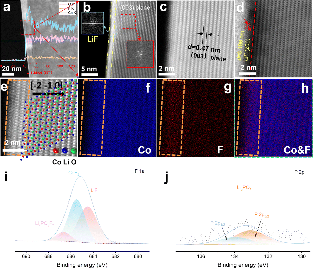
The interfacial fluorination process of 4.6 V F-LCO was achieved by wet uniform coating of a commercial 4.45 V pristine LCO (named P-LCO) with trace LiPF6 (LiPF6/LCO = 1 wt%), followed by thermal pyrolysis at 600 °C (Scheme S1, ESI†). It can be clearly seen that a ∼10 nm deep fluorination region is created near the subsurface of F-LCO (Fig. 1a and Fig. S1a, b, ESI†). Scanning transmission electron microscopy (STEM)–energy dispersive spectroscopy (EDS) line scanning reveals that the fluorination region (10–20 nm) forms isovalent cobalt relative to the bulk phase owing to gradient diffusion of F element as well as some P element from PF6− (Fig. S1c, ESI†). Notably, an atomically thin (∼1 nm) LiF covering layer is tightly formed on the surface of LCO as confirmed by Fourier transformation of the diffraction spots (Fig. 1b and Fig. S1b, ESI†). Further, STEM-high angle annular dark field (HAADF)/annular bright field (ABF) mode (Fig. 1c and d) clearly validates the (200) crystal plane of LiF (marked in Fig. 1d). Fig. 1e shows an atomically resolved STEM-HAADF image of F-LCO and the corresponding atomic structure model. The intuitive EDS elemental mappings of Co and F along with their overlay (Fig. 1f–h) indicate that the ultrathin LiF layer achieves a dense and continuous LCO lattice coverage with simultaneous near-surface lattice gradient fluorination (Co–O/F&P–O). X-ray electron photoelectron spectroscopy (XPS) analysis confirms that LiF, CoF2, and P–O species are widely distributed in the fluorination reconstructed cathode interface (Fig. 1i and j). Moreover, F, being the most electronegative element, in the ultrathin dense LiF layer can effectively cap the edge unsaturated active Co by forming Co–F bonding to inhibit its dissolution (Fig. S1d, ESI†).35,39,40 Such unique effect was not observed in P-LCO (Fig. S2a–h, ESI†). Moreover, the STEM-HAADF images (Fig. S2d, ESI†) of P-LCO display many edge-isolated unsaturated cobalt atoms or some low-valence CoO rock salt phases, which explains its susceptibility to induce side reactions with the electrolyte and be attacked by HF mainly derived from electrolyte decomposition.41
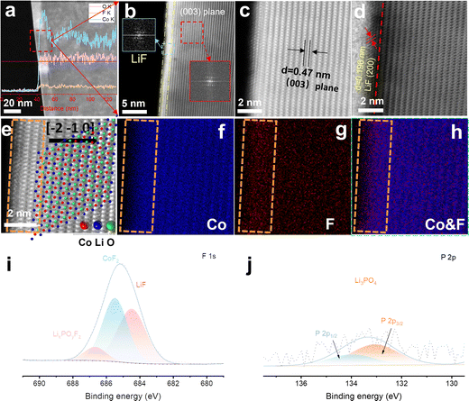 |
| | Fig. 1 Structural characterization and compositional analysis of the fluorination interfaces of F-LCO. (a) STEM-HAADF image of F-LCO (the inset shows the EDS line scan spectra along the red line across from the electrode particle surface to the bulk phase). (b) High resolution STEM-HAADF image of F-LCO (the inset shows the fast Fourier transform (FFT) pattern of LiF and LCO). (c) and (d) Enlarged image from (b) the STEM-HAADF/ABF mode using a spherical aberration corrected transmission electron microscope. (e) Atomic-resolution STEM-HAADF image of the subsurface for F-LCO at a 2 nm scale and the ordered atomic structure model features of the (003) plane corresponding to image (c) (the zone axis is [−2−10]). (f)–(h) EDS elemental mapping of (f) CO and (g) F from image and (h) their overlay. (i) F 1s and (j) P 2p XPS spectra of F-LCO. | |
High voltage and fast-charging of F-LCO
To highlight the key importance of the fluorinated interfacial structure, the electrochemical performance of both F-LCO and P-LCO was examined in the voltage range of 3.0–4.6 V (vs. Li+/Li) at room temperature. Notably, it is observed from the 1000 fast-charging cycles at 3C (1C = 274 mA g−1) (Fig. 2a and Fig. S3, ESI†) that F-LCO achieves a 92% capacity retention (155 mA h g−1), far beyond that of P-LCO (31%, 55 mA h g−1), outperforming most existing works (Table S1, ESI†). Importantly, F-LCO maintains a stable voltage profile (Fig. 2b) and voltage plateau (Fig. S4, ESI†) during the long-term fast-charging cycle compared to P-LCO (Fig. 2c and Fig. S4, ESI†). In sharp contrast, P-LCO displays a rapid capacity/voltage fading after 300 cycles, suggesting that fast charging cycles exacerbate oxygen loss and rapid structural degradation due to the cobalt migration through oxygen vacancies.14,19,20 Also, F-LCO exhibits an extraordinarily enhanced rate capability (Fig. S5 and S6, ESI†), delivering capacities of 209, 202, 194, 182, 174, 162, 141 and 213 mA h g−1 at 0.2, 0.5, 1, 2, 3, 5, 10 and 0.2C, respectively, while P-LCO shows correspondingly lower discharge capacities of 208, 201, 193, 181, 171, 158, 135 and 209 mA h g−1 at the same rate. Although F-LCO and P-LCO exhibit comparable rate performance, achieving excellent cell cycling stability under high current density cycling conditions is particularly challenging. As the performance improvement at full rate would also be closely related to the matched electrolyte, we are also currently working on this topic and further exploring the relationship between the artificial fluorination interphase and the electrolyte reaction kinetics. Further, the first galvanostatic charge/discharge (GCD) profiles of F-LCO (Fig. S7, ESI†) confirm the lower polarization and superior rate capability over P-LCO. During cycling at 1 C, F-LCO delivers an initial discharge capacity of 187 mA h g−1 and a 97% capacity retention over 200 cycles at 28 °C (Fig. S8a, ESI†), whereas P-LCO exhibits a lower capacity retention of 92.8% over the same number of cycles. In addition, at a high temperature of 45 °C, the capacity retention of F-LCO (82%) is higher than that of P-LCO (72%) after 200 cycles at 1 C (Fig. S8b, ESI†). Further, an assembled pouch-type full cell of graphite||F-LCO (Fig. 2d and Fig. S9, ESI†) exhibits incredible cycling stability without capacity attenuation over 1100 cycles at 252 mA (∼5C) within 3.0–4.5 V, demonstrative of the practicality in applications.
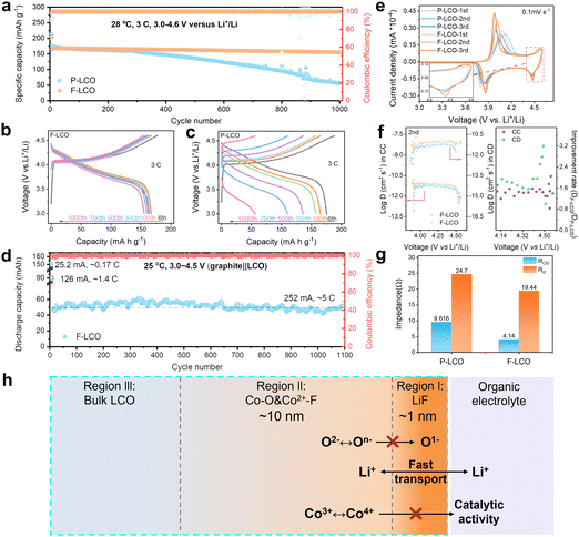 |
| | Fig. 2 Electrochemical performance of F-LCO and P-LCO in Li||LCO half cells and graphite||LCO full cells. (a) Long-term cyclability of Li||LCO half-cells at 3C within 3.0–4.6 V. (b) and (c) GCD profiles of F-LCO and P-LCO cathodes at 3C within 3.0–4.6 V in half-cells. (d) Cycling stability of graphite||F-LCO pouch-type full cells at 1C from 3.0 to 4.55 V. (e) CV curves of the first three cycles for F-LCO and P-LCO at 0.1 mV s−1 the inset shows an enlarged image of the high voltage region near 4.5 V in (e). (f) Li+ diffusion coefficients of F-LCO and P-LCO in the 2nd cycle obtained from GITT results and the corresponding improvement ratio graphs. (g) Impedance of F-LCO and P-LCO after 100 cycles at 3C obtained from Nyquist plots. (h) Schematic showing the interface structure of F-LCO from the surface to the bulk. Region (i): ultrathin lattice-matched epitaxial LiF compact layer; region (ii): Co–O/F&P–O gradient fluorination region; and region (iii): bulk LCO. | |
To testify the electrochemical enhancement mechanism of interfacial fluorination on LCO cathode reaction kinetics, the cyclic voltammetry (CV) curves of both F-LCO and P-LCO at a sweep rate of 0.1 mV s−1 were examined (Fig. 2e). It is observed that both F-LCO and P-LCO show typical redox peaks at approximately 4.4 and 3.8 V corresponding to the M2/H3 and H2/H1 phase transitions, respectively.1,2 F-LCO exhibits narrower and higher reversible redox peaks, and smaller polarization than P-LCO over progressive CV scans, clearly indicating faster charge transfer kinetics and greatly enhanced Co3+/Co4+ redox activity of F-LCO. Besides, the stronger cathodic peak, especially near 4.55 V, confirms the high structural stability and lattice oxygen redox reversibility of F-LCO at high voltages.28 The fast kinetics closely related to the Li+ diffusivity was revealed by galvanostatic intermittent titration technique (GITT) analysis (Fig. 2f and Fig. S10, ESI†). It is verified that the fluorination interface significantly enhances Li+ diffusion in F-LCO, especially during the O3 to H1-3 phase transition, compared to P-LCO (Fig. 2f). Evidently, further comparison of Nyquist plots (open circuit voltage state before the CV scan and 0.1 mV s−1 after three CV cycles) elucidates that the charge transfer resistance (Rct) of F-LCO decreases significantly with cycling, while P-LCO increases significantly compared to the initial Rct state (Fig. S11, ESI†), indicating that interfacial fluorination can induce the formation of a high-quality CEI layer in the early cycling. It is noted that, after 100 cycles at 3C (Fig. 2g and Fig. S12, ESI†), F-LCO also displays a significantly lower CEI impedance (RCEI) and Rct than P-LCO. Thus, it is confirmed that the interfacial fluorination not only facilitates the formation of high-quality interfacial structures, but also ensures the rapid Li+ diffusion and charge transfer, enabling high-voltage fast charging. As schematically illustrated in Fig. 2h, the unique fluorination interface structure synchronizes the nanoscale LiF covering layer (region I) and near-surface gradient fluorination region together with P–O (region II). As such, it is assumed that the epitaxial LiF covering layer acts as a physical barrier to isolate the interfacial side reactions, and the internal Co–O/F&P–O gradient fluorination region stabilizes the near-surface lattice oxygen to suppress the migration of highly reactive O− and the catalytic activity of Co4+. Ultimately, it helps maintain the stability of the electrode interface structure despite the high-voltage and fast-charging condition.
Enhanced electrolyte|cathode interface stability
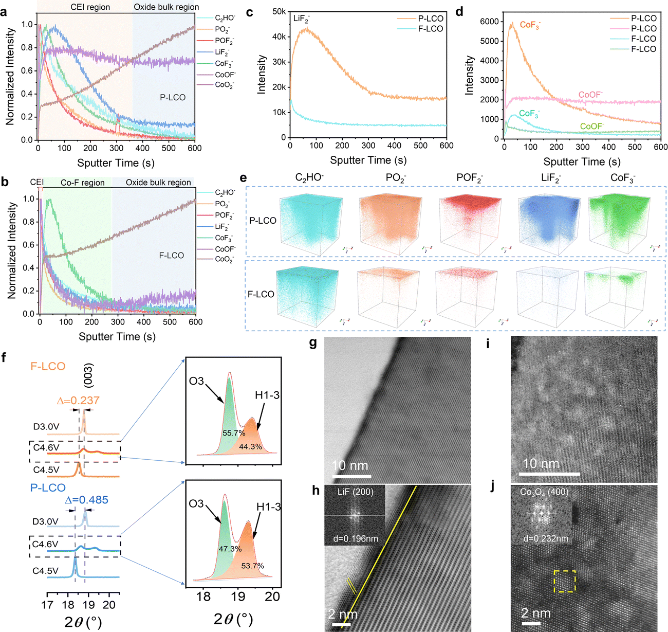
To gain key insight into the evolution and configuration of the CEI layer, we first confirmed the composition of the employed electrolyte (LiPF6 dissolved into FEC and FEMC solvent systems) by Raman spectroscopy (Fig. S13a, ESI†). Next, time of flight secondary-ion mass spectrometry (TOF-SIMS) analysis was conducted to reveal the surface chemical composition of F-LCO at different stages (Fig. S13b, c, ESI,† and Fig. 3a–e). We probed for the signals of C2HO−, PO2−, POF2−, LiF2−, CoF3−, CoOF−, and CoO2− from the composition of the CEI, electrolyte decomposition, and cobalt dissolution.15,31,42 The results suggest that oxygen loss and cobalt dissolution of F-LCO were efficiently suppressed during the first cycle due to the reconstruction of the Co–O/F&P–O@LiF interface (Fig. S13b, ESI†). In contrast, P-LCO displays significant cobalt dissolution and migration owing to the surface instability as evidenced by the distribution of CoF3−/CoOF−, and serious electrolyte side reactions validated by the bimodal distribution of LiF2−/PO2− (Fig. S13c, ESI†).15,31,43 The normalized TOF-SIMS depth profiles for cycled F-LCO and P-LCO reveal that the CEI gradually evolves into different structures after 1000 cycles at 3 C owing to their differing interfacial stabilities (Fig. 3a and b). Evidently, F-LCO with an ultrathin CEI (almost in line with the 1–2 nm-thick LiF layer) preserves its lattice integrity at the interface (CoO2− plateau corresponding to a 0.5 initial normalization ratio) resulting from the lattice stabilization mechanism of Co–O/F&P–O@LiF, while P-LCO exhibits a much thicker CEI layer (∼30 nm) and low lattice preservation (0.3 initial normalization ratio for CoO2−). It is thus validated that both cobalt dissolution and interfacial side reactions in F-LCO are highly suppressed by interfacial fluorination (Fig. 3c, d and Fig. S14, S15, ESI†). It is also suggested that the near-surface lattice achieves a highly reversible oxygen redox reaction through a trace gradient Co–F reconstruction (indicated by CoF3−) to suppress the irreversible evolution and propagation of On− and oxygen vacancies. This is explained by the fact that near-surface gradient fluorination not only forms a stronger Co2+–F (435 kJ mol−1) compared to Co–O (368 kJ mol−1),44 which contributes to the stabilization of the surface oxygen lattice framework, but also the larger ionic radius of Co2+ [r(Co2+) = 0. 65 Å] compared to Co3+ [r(Co3+) = 0.545 Å]/Co4+ [r(Co4+) = 0.535 Å] in the near surface can significantly enlarge the Li+ diffusion channel for fast charge–discharge at a high current rate.1,9,45 Simultaneously, the ultrathin dense LiF (indicated by LiF2−) covering layer together with strong P–O bonding resembles an interfacial shielding shell that efficiently isolates the catalytic decomposition of Co4+ and O− to the electrolyte and avoids the attack of electrolyte-derived HF on the lattice.10,35 Furthermore, the cathode surface chemistry rich in LiF, Co–F and LixPOyFz derived from the pyrolysis of LiPF6 has an inherent affinity with the electrolyte environment and can preferentially induce the derivation of LiF-rich inorganic CEI layers at the cathode–electrolyte interface, which is equivalent to the third protective wall. As shown in Fig. S16 and S2i–p (ESI†), the CoOF− located between LiF2− and CoF3− in F-LCO implies a continuous gradient hybrid interface of Co-O/F&P-O@LiF. It is like a potential well trench in the near-surface lattice, which also contributes to the suppression of cobalt migration/dissolution and lattice oxygen loss. More intuitively, the 3D reconstruction of the CEI layer obtained from TOF-SIMS results (Fig. 3e) discloses that the reconstructed interface confers F-LCO with a continuous, thin, and dense CEI indicated by PO2−, POF2− and LiF2−, thus preserving a highly stable structure and reaction kinetics even after 1000 cycles at 3C.
 |
| | Fig. 3 The stability analysis of the interfacial structure and CEI layer for cycled F-LCO and P-LCO under high voltage and fast-charging conditions. (a) and (b) Normalized TOF-SIMS depth profiles of representative species on cycled (a) P-LCO and (b) F-LCO cathodes after 1000 cycles in half cells. (c) and (d) Unnormalized TOF-SIMS depth profiles of (c) LiF2− and (d) COF3−, COOF−. (e) 3D reconstruction of the C2HO−, PO2−, POF2−, LiF2−, COF3−, COOF−, and COO2− fragments of P-LCO (top) and F-LCO (down) surfaces after 1000 cycles. (f) Ex situ XRD patterns of F-LCO and P-LCO at different states of charge. (g)–(j) Atomic-resolution STEM-HAADF images of (g) and (h) F-LCO and (i) and (j) P-LCO after 1000 cycles. The insets in (h) and (j) show the FFT patterns of LiF and Co3O4, respectively. | |
Next, we compared the effect on the structure of reconstructed F-LCO with P-LCO (Fig. S17, ESI†). The X-ray diffraction (XRD) patterns of both F-LCO and P-LCO present the same characteristic peaks, suggesting a typical layered structure of LCO (space group: R![[3 with combining macron]](https://www.rsc.org/images/entities/char_0033_0304.gif) m, JCPDS No. 50-0653).28 Further, XRD patterns at different high-voltage charge states and fully discharged states display that the (003) peak of F-LCO between 4.5 and 3.0 V shifts by only 0.237°, while in the case of P-LCO, it is as high as 0.485° (Fig. 3f). Clearly, the interfacial fluorination greatly improves the phase transition reversibility of F-LCO at high voltage states. Moreover, we observe the lower relative intensity of the H1-3 peak in F-LCO (44.3%) in comparison with P-LCO (53.7%) at 4.6 V (Fig. 3f), which confirms that interfacial fluorination can effectively reduce the proportion of the H1-3 phase.37 It is interpreted that the subsurface lattice of F-LCO is strengthened in the high voltage state, extraordinarily improving the reversibility of the lattice oxygen redox. This is also visually demonstrated by the STEM images of F-LCO after 1000 cycles, where the interfacial fluorination effectively keeps the electrode structure stable with minimal structural degradation after long-term cycling (Fig. 3g and h). However, the unfluorinated P-LCO (Fig. 3i and j) undergoes severe structural degradation over the same number of cycles, manifesting as numerous voids on the surface of the cathode and accounting for the large proportion of the local spinel phase (Co3O4) derived from Co dissolution and O loss.10,22
m, JCPDS No. 50-0653).28 Further, XRD patterns at different high-voltage charge states and fully discharged states display that the (003) peak of F-LCO between 4.5 and 3.0 V shifts by only 0.237°, while in the case of P-LCO, it is as high as 0.485° (Fig. 3f). Clearly, the interfacial fluorination greatly improves the phase transition reversibility of F-LCO at high voltage states. Moreover, we observe the lower relative intensity of the H1-3 peak in F-LCO (44.3%) in comparison with P-LCO (53.7%) at 4.6 V (Fig. 3f), which confirms that interfacial fluorination can effectively reduce the proportion of the H1-3 phase.37 It is interpreted that the subsurface lattice of F-LCO is strengthened in the high voltage state, extraordinarily improving the reversibility of the lattice oxygen redox. This is also visually demonstrated by the STEM images of F-LCO after 1000 cycles, where the interfacial fluorination effectively keeps the electrode structure stable with minimal structural degradation after long-term cycling (Fig. 3g and h). However, the unfluorinated P-LCO (Fig. 3i and j) undergoes severe structural degradation over the same number of cycles, manifesting as numerous voids on the surface of the cathode and accounting for the large proportion of the local spinel phase (Co3O4) derived from Co dissolution and O loss.10,22
Mechanism of inhibiting the active oxygen species loss
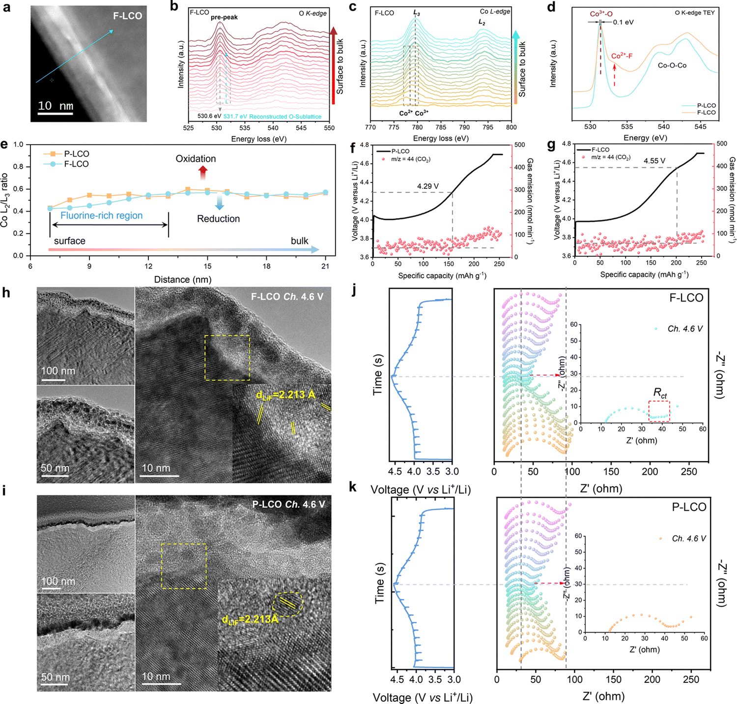
To establish a detailed structure–performance relationship emerging from the fluorination interface, electron energy loss spectroscopy (EELS) measurements were performed to investigate the valence variation of Co and O from the edge to the bulk lattice for F-LCO and P-LCO under the STEM-HAADF mode (Fig. 4a–d and Fig. S18–20, ESI†). It was found that interfacial fluorination triggers a significant transition metal (TM) reduction (Co3+ reduction to Co2+ as indicated by the Co L3 edge in Fig. 4c and the L2/L3 ratio in Fig. 4d) and formation of new defects in the near-surface lattice oxygen (by the pre-edge peak, ∼530.6 eV, of the O K-edge in Fig. 4b) in the fluorinated region of F-LCO compared to P-LCO.22,46–53 The pre-edge peak at 778.5 eV appears in the Co L3-edge (Fig. 4b), which is the characteristic of Co2+ with octahedral local coordination in F-LCO.54,55 This observation suggests that F diffuses into the lattice oxygen framework to optimize the coordination environment and valence state of the original Co and thus satisfy the new charge balance requirements. Simultaneously, the pre-peak of the O K-edge at 531.7 eV also presents an obvious trend of peak splitting corresponding to the appearance of Co2+. Moreover, the main peak position of the O pre-peak for F-LCO changes to 530.6 eV relative to 531 eV for P-LCO (Fig. S19a–c, ESI†), further proving that interfacial fluorination changes the Co–O bonding of the near-surface lattice. Further, the line scan analysis of STEM-HAADF images at high resolution is shown in Fig. S18a and b (ESI†). Upon normalizing the L3-edge of Co (Fig. 4e and Fig. S20a, b, ESI†), it is observed that the Co L2/L3 ratio of F-LCO increased from the surface to the bulk phase and the L2-edge gradually shifts to the higher energy-loss region, generating abundant new defects in the near-surface lattice of F-LCO, compared to P-LCO (Fig. 4e).52,56–59 This can be interpreted as a local coordination transition in Co–O/F&P–O@LiF caused by the fluorination-derived Co2+, which not only facilitates the rapid transport of Li+ but also stabilizes the lattice oxygen framework, consistent with theoretical calculations.22,60 To further confirm the EELS results, soft X-ray absorption spectroscopy (SXAS) was performed in the total electron yield (TEY) mode (Fig. 4d).15,55,61 The O K-edge TEY-SXAS spectra of both F-LCO and P-LCO show strong Co3+–O signal peaks excited from the O 1s orbital to the O 2p–Co 3d hybrid orbital at 531.3 eV and 531.4 eV, respectively. The emerging peak at 532.5 eV in F-LCO is attributed to the Co2+–F, indicating partial reduction of Co3+ to Co2+, which confirms the presence of Co–F bonding again in the reconstructed near-surface O sublattice.15,29,55 It can be intuitively assumed that gradient Co–F bonding reduces the inherent O sublattice defects of P-LCO, which is also confirmed by electron paramagnetic resonance (EPR) results (Fig. S20c, ESI†).62,63 It is noted that F-LCO displays a weaker signal at g = 2.14 than P-LCO, thus greatly improving the reversibility of oxygen redox reactions during high-voltage fast-charging cycles.12,60,64 As a key gas product indicating an irreversible high-valent oxygen evolution reaction, CO2 can clearly reflect the suppression effect on oxygen loss. Based on the trend of CO2 gas product production (Fig. 4f and g), in situ differential electrochemical mass spectrometry (DEMS) tests further confirm that fluorination can effectively inhibit high-valent oxygen evolution by delaying the onset potential of the oxidative decomposition of the electrolyte from 4.29 V (P-LCO) to 4.55 V (F-LCO). Since the labile high-valent oxygen in the surface lattice is highly susceptible to migrate and oxidize the electrolyte components and produce CO2, the significantly reduced CO2 and delayed gas generation onset potential demonstrate that fluorination suppresses the catalytic decomposition effect of the deep delithiated cathode surface lattice on the electrolyte.5,65 To further elucidate the intrinsic mechanism of interfacial fluorination for enhancing oxygen redox reversibility, we performed the oxygen evolution reaction (OER) to check the activity of F-LCO in 1 M KOH aqueous solution (Fig. S20d and e, ESI†). Interestingly, F-LCO shows better kinetics with a smaller overpotential (ηOER = 378 mV) compared to P-LCO (ηOER = 424 mV) at 6 mA cm−2, evidencing its stronger charge transfer capability. Such a property, in turn, is more conducive to preferentially induce the formation of a LiF-rich inorganic CEI (with an affinity to the dense continuous LiF covering layer) to achieve lower interfacial impedance and electrode polarization at high current rates. This is visually confirmed by the distribution of the CEI on the electrode surface when first charged to 4.6 V (Fig. 4h and i). When charged to a highly delithiated state at 4.6 V, the dense LiF covering layer (with a strong electronegativity of F) on the F-LCO surface not only retains close contact with the LCO lattice but also instigates the in situ formation of a dense and thin LiF-rich inorganic hybrid CEI (Fig. 4i). In contrast, P-LCO suffers from severe interfacial side reactions derived from the high electrode surface reactivity in the highly delithiated state, resulting in an inner ∼20 nm organic-rich CEI layer and an outer ∼10 nm LiF-rich inorganic CEI layer (Fig. 4h). This is because the electrode interface chemistry and lattice structure of commercial P-LCO have not been sufficiently stabilized at a high voltage of 4.6 V (Table S2, ESI†). More comprehensively, the in situ EIS tests in Fig. 4j and k during the first charge/discharge process further reveal the key mechanism of fluorination in optimizing the CEI as well as the charge transfer process. When charged close to 4.6 V, the EIS of F-LCO exhibits significant Rct, lower RCEI, and stronger diffusion capability due to the presence of the fluorination interface compared to P-LCO. Moreover, the RCEI of F-LCO at the end of the discharge period shows a significant decreasing trend compared to the beginning of the charge period, while the opposite is observed for P-LCO. Such interfacial convergence properties fully ensure the efficient operation of the Co/O redox within the fluorinated interface lattice, as evidenced by the significant high-valent oxygen signal detected by O K-edge TEY-SXAS spectra (Fig. S20f and g, ESI†) and the significantly reduced side reaction intermediate LixPOyFz signal measured by XPS (Fig. S20h and i, ESI†) in the near-surface lattice of F-LCO when charged to the 4.6 V high-voltage state after 20 cycles, compared to P-LCO. It is indicated that the cathode near-surface lattice can effectively store high-valent oxygen and achieve its reversible transformation under the confinement of the fluorinated interface lattice. Therefore, the reconstructed interfacial lattice by fluorination directly stabilizes the surface Co4+/Co3+ redox and enhances the reversibility of oxygen redox at a deep delithiated state through Co2+–F/LiF. The Co–O/F&P–O@LiF interface structure of F-LCO and its benefits can be further verified by XPS (Fig. S21a–f, ESI†). From the F 1s XPS spectrum (Fig. S21a and b, ESI†), it is observed that the LiPF6 on the surface of LCO gradually evolves into LiF and Co–F&P–O due to the gradient penetration of F ions as the annealing temperature increases. Quantitative XPS analysis shows that F-LCO has a comparable ratio of LiF to Co–F and suggests that the interfacial fluorination may have reached a relatively equilibrium state (Fig. S21b, ESI†). Synchronously, the weak phosphate species signal indicated by the P 2p spectrum in F-LCO may also trap oxygen radical species through P–O bonding to help stabilize the surface/interface lattice of LCO (Fig. S21c and d, ESI†),37 while the weaker P signal above 500 °C indicates that the stabilization of near-surface lattice oxygen is overwhelmingly attributable to interfacial fluorination. Consequently, as F penetrates the material,
there is a notable transformation of the near-surface lattice oxygen, reinforcing the structure. This change is captured in the O 1s spectrum, where F-LCO demonstrates a marked increase in the presence of strong lattice oxygen bonds (Fig. S21e and f, ESI†). Therefore, our cathode interface fluorination engineering not only provides robust LiF-lattice mechanical strain adaptability but also optimizes the interfacial chemical properties, facilitates the formation of high-quality CEI structures, and enhances the reversibility of Co/O redox, which is crucial for stabilizing high-voltage fast-charging F-LCO.
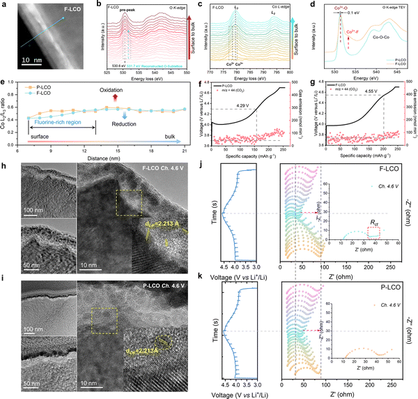 |
| | Fig. 4 Fundamental mechanism for stabilizing the near-surface lattice and inhibiting the reactive oxygen species loss. (a) EELS line scan at the surface of F-LCO single crystal particles under the STEM-HAADF mode. (b) and (c) EELS spectra of (b) O K-edges and (c) Co L-edges collected from F-LCO. (d) O K-edge SXAS spectra of F-LCO and P-LCO under the TEY mode. (e) The Co L3/L2 peak intensity ratio from (c). (f) and (g) In situ DEMS test for (f) P-LCO and (g) F-LCO by performing charging from 3.0 to 4.7 V. (h) and (i) STEM-HAADF images of (h) F-LCO and (i) P-LCO when charged to 4.6 V at the 1st cycle. (j) and (k) In situ EIS test of F-LCO and P-LCO during the first cycle at 0.2C. | |
Theoretical understanding in suppressing Co dissolution and O loss
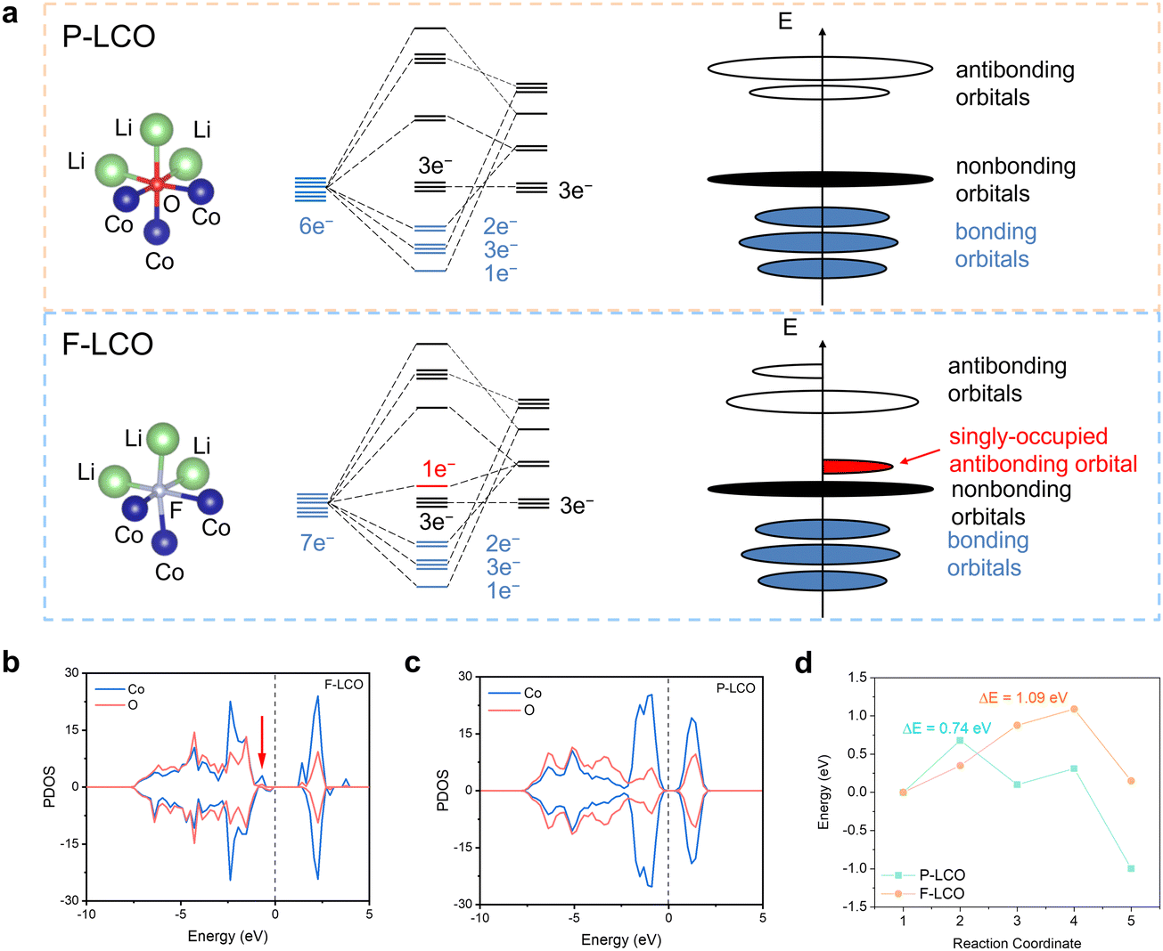
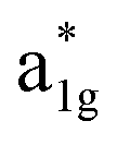
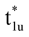
The fundamental mechanism behind the suppression of Co dissolution and O loss of F-LCO by fluorination interfacial reconstruction was explored through DFT calculations. Every O atom in LCO bulk is coordinated by three Co and three Li atoms (Fig. 5a). It is generally considered that the interactions between O and Li atoms are weak because the energy levels of O 2p and Li 2s orbitals are greatly mismatched. In contrast, the energy levels of O 2p and Co 3d are close enough to form stable Co–O bonds.17,66 According to the ligand field theory, the Co–O interaction results in the splitting of energy levels and the formation of a1g, t1u, and eg bonding orbitals that are mainly formed by electronic states from the O 2p orbital,  ,
,  , and
, and  antibonding orbitals by those mainly from the Co 3d orbital, along with a nonbonding orbital t2g composed of Co 3d orbitals.67 LCO exhibits non-magnetism with t2g orbitals fully occupied by 6 electrons from Co3+, consistent with previously reported results (Fig. 5b).67 However, F ([He]2s22p5) has one extra valence electron compared to O ([He]2s22p4), while the number of bonding orbitals formed by F and Co atoms remains the same (Fig. 5a). Consequently, one of the
  antibonding orbitals is singly occupied and moves downwards in energy with F substitution, generating spin-polarization in the projected density of states (PDOS) (Fig. 5c). In LCO, when the cathode charging approaches 4.6 V, the Fermi energy level (EFermi) shifts to a lower energy state. In such a case, the bonding orbital becomes partially occupied and causes the weakening of the Co–O bond. But since there is a singly occupied anti-bonding
  orbital with F substitution, electrons get transferred from the occupied
  orbitals instead of eg orbitals, which results in the enhancement of Co–F bonds and makes Co dissolution more difficult. The spin density in Fig. S22 (ESI†) demonstrates spin polarization in the Co atom after F diffusion, in accordance with PDOS analysis. Furthermore, upon the investigation of the O loss mechanism, the migration of O species in LCO is considered to follow the so-called vacancy mechanism.18 In other words, the O species migrate by changing positions with O vacancies. The kinetics of such migration is investigated by the climbing image nudged elastic band (CI-NEB) method,39 with the diffusion path shown in Fig. S23 (ESI†). It is demonstrated that the introduction of F atoms into LCO can increase the energy barrier of oxygen migration from 0.74 to 1.09 eV (Fig. 5d). Since the dense LiF capping layer on the surface induces the formation of a LiF-rich outer CEI, this further effectively suppresses oxygen loss and cobalt dissolution. It is reasonably elucidated that these processes (Co–F enhanced by electron transfer from the occupied anti-bonding
  orbital and increased migration barrier for O atoms) work simultaneously to promote stable electrochemical properties in F-LCO at a voltage as high as 4.6 V.
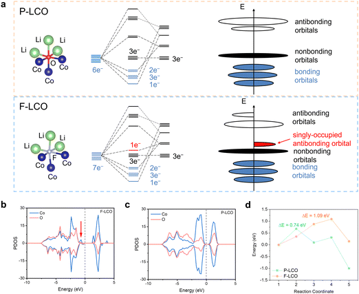 |
| | Fig. 5 DFT simulations to illustrate the mechanism of stabilizing the evolution of high-valent oxygen by fluorination bonding. (a) Molecular orbital energy diagrams in P-LCO (up) and F-LCO (bottom) crystals and the corresponding schemes of energy levels in LCO without F (up) and with F substitution (bottom). (b) and (c) PDOS of (b) P-LCO and (c) F-LCO. The Fermi energy level is set to zero. (d) Diffusion energy barrier of Li+ in F-LCO with F substitution and P-LCO without F substitution. | |
Conclusions
In summary, we demonstrate a reliable cathode interface fluorination engineering strategy to effectively suppress oxygen loss and cobalt dissolution in 4.6 V F-LCO, achieving extraordinarily fast 3 C charging with long-term cyclability. Driven by the fluorination engineering of the surface/near-surface lattice chemistry, F-LCO not only achieves an ultrathin dense LiF conformal covering layer, but also a near-surface lattice with Co–F gradient fluorination. Consequently, F-LCO at 4.6 V achieves an incredible 92% capacity retention after 1000 cycles under 3 C fast charging in a Li||LCO cell. More impressively, F-LCO exhibits unprecedented high voltage cycling stability in a practical pouch-type graphite||LCO full cell. A consistent explanation for the experimentally observed retention of structural integrity and reversible oxygen redox is formulated through theoretical simulations, whereby a novel mechanism of enhanced ion transport at the fluorination bonding interface and inhibition of Co dissolution and O loss by Co–F gradient lattice reconstruction is demonstrated. We believe that the proposed cathode interface fluorination engineering strategy will offer more opportunities to generate a functional artificial CEI layer for high-voltage and fast-charging cathodes to propel advanced energy storage devices to new heights.
Author contributions
Z.-S. W., F. P., and C. C. conceived the experiments and supervised this project. Z. B. synthesized the materials and conducted the electrochemical measurements. Z. Y. and C. C. conducted the DFT simulations. S. L., X. S., and Z. B. assembled and tested the pouch-type full cells. M. L., N. T., W. Z., and L. Z. conducted the STEM–EELS characterization. J. M., L. S., and S. W. conducted the SXAS measurements. Z. P. and Z. Z. conducted the DEMS measurements. Y. W. conducted the LSV measurements. Z. B., Z. Y., L. Z., G. W., A. Z., Q. Z., S. L., S. L., P. D., Y. C., C. C., F. P., and Z.-S. W. wrote the paper.
Conflicts of interest
There are no conflicts to declare.
Acknowledgements
This work was financially supported by the National Key R&D Program of China (Grant 2022YFA1504100), the National Natural Science Foundation of China (Grant No. 22125903 and 22005298), Dalian National Laboratory for Clean Energy (DNL), CAS, DNL Cooperation Fund, CAS (DNL202016 and DNL202019), the Joint Fund of the Yulin University and the Dalian National Laboratory for Clean Energy (YLU-DNL Fund 2021002 and YLU-DNL Fund 2021009), and the Exploratory Research Project of Yanchang Petroleum International Limited and DICP (yc-hw-2022ky-01). We acknowledge the Hefei Synchrotron Radiation Facility for conducting the SXAS experiment (MCD-A and MCD-B Soochow Beamline for Energy Materials at NSRL) and the Vacuum Interconnected Nanotech Workstation (NANO-X) for conducting the FIB and TOF-SIMS experiments. We thank Prof. Yi Cui, Tong Liu and Rong Huang in the Vacuum Interconnected Nanotech Workstation (NANO-X) (Suzhou Institute of Nanotechnology and Nano-bionics, Chinese Academy of Sciences) for kindly conducting FIB and TOF-SIMS characterization.
Notes and references
- L. Wang, B. Chen, J. Ma, G. Cui and L. Chen, Chem. Soc. Rev., 2018, 47, 6505–6602 RSC.
- Y. Lyu, X. Wu, K. Wang, Z. Feng, T. Cheng, Y. Liu, M. Wang, R. Chen, L. Xu, J. Zhou, Y. Lu and B. Guo, Adv. Energy Mater., 2020, 11, 2000982 CrossRef.
- Q. Li, Q. Liang, H. Zhang, S. Jiao, Z. Zhuo, J. Wang, Q. Li, J. N. Zhang and X. Yu, Angew. Chem., Int. Ed., 2023, 62, e202215131 CrossRef CAS.
- K. Wang, J. J. Wan, Y. X. Xiang, J. P. Zhu, Q. Y. Leng, M. Wang, L. M. Xu and Y. Yang, J. Power Sources, 2020, 460, 228062 CrossRef CAS.
- M. Z. Cai, Y. H. Dong, M. Xie, W. J. Dong, C. L. Dong, P. Dai, H. Zhang, X. Wang, X. Z. Sun, S. N. Zhang, M. Yoon, H. W. Xu, Y. S. Ge, J. Li and F. Q. Huang, Nat. Energy, 2023, 8, 159–168 CrossRef CAS.
- S. D. Zhang, M. Y. Qi, S. J. Guo, Y. G. Sun, X. X. Tan, P. Z. Ma, J. Y. Li, R. Z. Yuan, A. M. Cao and L. J. Wan, Small Methods, 2022, 6, e2200148 CrossRef.
- H. Zhang, H. Liu, L. F. J. Piper, M. S. Whittingham and G. Zhou, Chem. Rev., 2022, 122, 5641–5681 CrossRef CAS.
- M. H. Zhang, D. A. Kitchaev, Z. Lebens-Higgins, J. Vinckeviciute, M. Zuba, P. J. Reeves, C. P. Grey, M. S. Whittingham, L. F. J. Piper, A. van der Ven and Y. S. Meng, Nat. Rev. Mater., 2022, 7, 522–540 CrossRef.
- Y. Dong and J. Li, Chem. Rev., 2022, 123, 811–833 CrossRef PubMed.
- W. Kong, J. Zhang, D. Wong, W. Yang, J. Yang, C. Schulz and X. Liu, Angew. Chem., Int. Ed., 2021, 60, 27102–27112 CrossRef CAS PubMed.
- E. Hu, Q. Li, X. Wang, F. Meng, J. Liu, J.-N. Zhang, K. Page, W. Xu, L. Gu, R. Xiao, H. Li, X. Huang, L. Chen, W. Yang, X. Yu and X.-Q. Yang, Joule, 2021, 5, 720–736 CrossRef CAS.
- W. J. Kong, D. Wong, K. An, J. C. Zhang, Z. H. Chen, C. Schulz, Z. J. Xu and X. F. Liu, Adv. Funct. Mater., 2022, 32, 2202679 CrossRef CAS.
- M. Wen, W. Kong, J. Zhang, Q. Zhang, W. Yin, N. Zhang, K. Chai, Y. Yu, H. Chen and X. Liu, ACS Energy Lett., 2022, 7, 4185–4189 CrossRef CAS.
- H. Zhang, B. M. May, F. Omenya, M. S. Whittingham, J. Cabana and G. Zhou, Chem. Mater., 2019, 31, 7790–7798 CrossRef CAS.
- Z. Zhu, H. Wang, Y. Li, R. Gao, X. Xiao, Q. Yu, C. Wang, I. Waluyo, J. Ding, A. Hunt and J. Li, Adv. Mater., 2020, 32, e2005182 CrossRef PubMed.
- B. Xiao and X. Sun, Adv. Energy Mater., 2018, 8, 1802057 CrossRef.
- J. Chen, W. Deng, X. Gao, S. Yin, L. Yang, H. Liu, G. Zou, H. Hou and X. Ji, ACS Nano, 2021, 15, 6061–6104 CrossRef CAS PubMed.
- P. Yan, J. Zheng, Z.-K. Tang, A. Devaraj, G. Chen, K. Amine, J.-G. Zhang, L.-M. Liu and C. Wang, Nat. Nanotechnol., 2019, 14, 602–608 CrossRef CAS PubMed.
- N. Yaqoob, R. Mücke, O. Guillon and P. Kaghazchi, J. Power Sources, 2022, 533, 231316 CrossRef CAS.
- S. Lee, W. Jin, S. H. Kim, S. H. Joo, G. Nam, P. Oh, Y. K. Kim, S. K. Kwak and J. Cho, Angew. Chem., Int. Ed., 2019, 58, 10478–10485 CrossRef CAS.
- Y. Huang, Y. Zhu, H. Fu, M. Ou, C. Hu, S. Yu, Z. Hu, C. T. Chen, G. Jiang, H. Gu, H. Lin, W. Luo and Y. Huang, Angew. Chem., Int. Ed., 2021, 60, 4682–4688 CrossRef CAS PubMed.
- C. Sun, X. Liao, F. Xia, Y. Zhao, L. Zhang, S. Mu, S. Shi, Y. Li, H. Peng, G. Van Tendeloo, K. Zhao and J. Wu, ACS Nano, 2020, 14, 6181–6190 CrossRef CAS PubMed.
- A. Yano, M. Shikano, A. Ueda, H. Sakaebe and Z. Ogumi, J. Electrochem. Soc., 2016, 164, A6116–A6122 CrossRef.
- B. Kim, J. Song, D. Eum, S. Yu, K. Oh, M. Lee, H. Jang and K. Kang, Nat. Sustain., 2022, 5, 708–716 CrossRef.
- G. Assat and J.-M. Tarascon, Nat. Energy, 2018, 3, 373–386 CrossRef CAS.
- A. Fu, Z. Zhang, J. Lin, Y. Zou, C. Qin, C. Xu, P. Yan, K. Zhou, J. Hao, X. Yang, Y. Cheng, D.-Y. Wu, Y. Yang, M.-S. Wang and J. Zheng, Energy Storage Mater., 2022, 46, 406–416 CrossRef.
- L. Wang, J. Ma, C. Wang, X. Yu, R. Liu, F. Jiang, X. Sun, A. Du, X. Zhou and G. Cui, Adv. Sci., 2019, 6, 1900355 CrossRef PubMed.
- J.-N. Zhang, Q. Li, C. Ouyang, X. Yu, M. Ge, X. Huang, E. Hu, C. Ma, S. Li, R. Xiao, W. Yang, Y. Chu, Y. Liu, H. Yu, X.-Q. Yang, X. Huang, L. Chen and H. Li, Nat. Energy, 2019, 4, 594–603 CrossRef CAS.
- N. Qin, Q. Gan, Z. Zhuang, Y. Wang, Y. Li, Z. Li, H. Iftikhar, C. Zeng, G. Liu, Y. Bai, K. Zhang and Z. Lu, Adv. Energy Mater., 2022, 12, 2201549 CrossRef CAS.
- S.-X. Chen, C.-W. Wang, Y. Zhou, J.-K. Liu, C.-G. Shi, G.-Z. Wei, B.-Y. Yin, H.-T. Deng, S.-Y. Pan, M.-J. Guo, W.-C. Zheng, H.-Z. Wang, Y.-H. Jiang, L. Huang, H.-G. Liao, J.-T. Li and S.-G. Sun, J. Mater. Chem. A, 2022, 10, 5295–5304 RSC.
- J. Chen, H. Chen, S. Zhang, A. Dai, T. Li, Y. Mei, L. Ni, X. Gao, W. Deng, L. Yu, G. Zou, H. Hou, M. Dahbi, W. Xu, J. Wen, J. Alami, T. Liu, K. Amine and X. Ji, Adv. Mater., 2022, 34, 2204845 CrossRef CAS PubMed.
- W. Zhang, X. Y. Zhang, F. Y. Cheng, M. Wang, J. Wan, Y. Y. Li, J. Xu, Y. Liu, S. X. Sun, Y. Xu, C. Fang, Q. Li, J. T. Han and Y. H. Huang, J. Energy Chem., 2023, 76, 557–565 CrossRef CAS.
- J. Qian, L. Liu, J. Yang, S. Li, X. Wang, H. L. Zhuang and Y. Lu, Nat. Commun., 2018, 9, 4918 CrossRef PubMed.
- T. J. Fan, W. Kai, V. K. Harika, C. S. Liu, A. Nimkar, N. Leifer, S. Maiti, J. Grinblat, M. N. Tsubery, X. L. Liu, M. Wang, L. M. Xu, Y. H. Lu, Y. G. Min, N. Shpigel and D. Aurbach, Adv. Funct. Mater., 2022, 32, 2204972 CrossRef CAS.
- W. Huang, Q. Zhao, M. Zhang, S. Xu, H. Xue, C. Zhu, J. Fang, W. Zhao, G. Ren, R. Qin, Q. Zhao, H. Chen and F. Pan, Adv. Energy Mater., 2022, 12, 2200813 CrossRef CAS.
- Y. Wang, Q. Zhang, Z. C. Xue, L. Yang, J. Wang, F. Meng, Q. Li, H. Pan, J. N. Zhang, Z. Jiang, W. Yang, X. Yu, L. Gu and H. Li, Adv. Energy Mater., 2020, 10, 2001413 CrossRef CAS.
- X. R. Yang, C. W. Wang, P. F. Yan, T. P. Jiao, J. L. Hao, Y. Y. Jiang, F. C. Ren, W. G. Zhang, J. M. Zheng, Y. Cheng, X. S. Wang, W. Yang, J. P. Zhu, S. Y. Pan, M. Lin, L. Y. Zeng, Z. L. Gong, J. T. Li and Y. Yang, Adv. Energy Mater., 2022, 12, 2200197 CrossRef CAS.
- T. Cheng, Z. T. Ma, R. C. Qian, Y. T. Wang, Q. Cheng, Y. C. Lyu, A. M. Nie and B. K. Guo, Adv. Funct. Mater., 2021, 31, 2001974 CrossRef CAS.
- S. Mao, Z. Shen, W. Zhang, Q. Wu, Z. Wang and Y. Lu, Adv. Sci., 2022, 9, 2104841 CrossRef CAS PubMed.
- H.-H. Ryu, H.-W. Lim, G.-C. Kang, N.-Y. Park and Y.-K. Sun, ACS Energy Lett., 2023, 8, 1354–1361 CrossRef CAS.
- J. L. Tebbe, A. M. Holder and C. B. Musgrave, ACS Appl. Mater. Interfaces, 2015, 7, 24265–24278 CrossRef CAS PubMed.
- C. G. Shi, X. X. Peng, P. Dai, P. H. Xiao, W. C. Zheng, H. Y. Li, H. Li, S. Indris, S. Mangold, Y. H. Hong, C. X. Luo, C. H. Shen, Y. M. Wei, L. Huang and S. G. Sun, Adv. Energy Mater., 2022, 12, 2200569 CrossRef CAS.
- G.-T. Park, H.-H. Ryu, T.-C. Noh, G.-C. Kang and Y.-K. Sun, Mater. Today, 2022, 52, 9–18 CrossRef CAS.
-
J. Dean, Lange's handbook of chemistry, 1999, 15, pp. 4.36–34.37 Search PubMed.
- R. D. Shannon, Acta Crystallogr., Sect. A: Cryst. Phys., Diffr., Theor. Gen. Crystallogr., 1976, 32, 751–767 CrossRef.
- F. Lin, D. Nordlund, I. M. Markus, T.-C. Weng, H. L. Xin and M. M. Doeff, Energy Environ. Sci., 2014, 7, 3077–3085 RSC.
- X. G. Xu, C. Li, J. X. Li, U. Kolb, F. Wu and G. Chen, J. Phys. Chem. B, 2003, 107, 11648–11651 CrossRef CAS.
- F. Lin, I. M. Markus, D. Nordlund, T.-C. Weng, M. D. Asta, H. L. Xin and M. M. Doeff, Nat. Commun., 2014, 5, 3529 CrossRef PubMed.
- D. Qian, B. Xu, M. Chi and Y. S. Meng, Phys. Chem. Chem. Phys., 2014, 16, 14665–14668 RSC.
- Y. Nomura, K. Yamamoto, T. Hirayama, M. Ohkawa, E. Igaki, N. Hojo and K. Saitoh, Nano Lett., 2018, 18, 5892–5898 CrossRef CAS PubMed.
- S. Sharifi-Asl, J. Lu, K. Amine and R. Shahbazian-Yassar, Adv. Energy Mater., 2019, 9, 1900551 CrossRef.
- R. Córdoba, R. Fernández-Pacheco, A. Fernández-Pacheco, A. Gloter, C. Magén, O. Stéphan, M. R. Ibarra and J. M. De Teresa, Nanoscale Res. Lett., 2011, 6, 592 CrossRef PubMed.
- S. Sharifi-Asl, F. A. Soto, A. Nie, Y. Yuan, H. Asayesh-Ardakani, T. Foroozan, V. Yurkiv, B. Song, F. Mashayek, R. F. Klie, K. Amine, J. Lu, P. B. Balbuena and R. Shahbazian-Yassar, Nano Lett., 2017, 17, 2165–2171 CrossRef CAS PubMed.
- W. Kong, D. Zhou, N. De, W. Yang, D. Wong, J. Zhang, Q. Li, J. Yang, C. Schulz and X. Liu, J. Electrochem. Soc., 2021, 168, 030528 CrossRef CAS.
- B. Hu, F. Geng, M. Shen, C. Zhao, Q. Qiu, Y. Lin, C. Chen, W. Wen, S. Zheng, X. Hu, C. Li and B. Hu, J. Power Sources, 2021, 516, 230661 CrossRef CAS.
- Y. Wu, H. Ming, M. Li, J. Zhang, W. Wahyudi, L. Xie, X. He, J. Wang, Y. Wu and J. Ming, ACS Energy Lett., 2019, 4, 656–665 CrossRef CAS.
- J. G. Lapping, S. A. Delp, J. L. Allen, J. L. Allen, J. W. Freeland, M. D. Johannes, L. Hu, D. T. Tran, T. R. Jow and J. Cabana, Chem. Mater., 2018, 30, 1898–1906 CrossRef CAS.
- B. Xu, C. R. Fell, M. Chi and Y. S. Meng, Energy Environ. Sci., 2011, 4, 2223–2233 RSC.
- P. Yan, J. Zheng, J.-G. Zhang and C. Wang, Nano Lett., 2017, 17, 3946–3951 CrossRef CAS PubMed.
- K. Zhou, S. Zheng, F. Ren, J. Wu, H. Liu, M. Luo, X. Liu, Y. Xiang, C. Zhang, W. Yang, L. He and Y. Yang, Energy Storage Mater., 2020, 32, 234–243 CrossRef.
- L. Hong, L. Hu, J. W. Freeland, J. Cabana, S. Öğüt and R. F. Klie, J. Phys. Chem. C, 2019, 123, 8851–8858 CrossRef CAS.
- A. Artemenko, M. Menetrier, M. Pollet and C. Delmas, J. Appl. Phys., 2009, 106 Search PubMed.
- R. Sharpe, R. A. House, M. J. Clarke, D. Förstermann, J.-J. Marie, G. Cibin, K.-J. Zhou, H. Y. Playford, P. G. Bruce and M. S. Islam, J. Am. Chem. Soc., 2020, 142, 21799–21809 CrossRef CAS PubMed.
- S. Xu, X. Tan, W. Ding, W. Ren, Q. Zhao, W. Huang, J. Liu, R. Qi, Y. Zhang, J. Yang, C. Zuo, H. Ji, H. Ren, B. Cao, H. Xue, Z. Gao, H. Yi, W. Zhao, Y. Xiao, Q. Zhao, M. Zhang and F. Pan, Angew. Chem., Int. Ed., 2023, 62, e202218595 CrossRef CAS PubMed.
- Z. Zhu, D. Yu, Z. Shi, R. Gao, X. Xiao, I. Waluyo, M. Ge, Y. Dong, W. Xue, G. Xu, W.-K. Lee, A. Hunt and J. Li, Energy Environ. Sci., 2020, 13, 1865–1878 RSC.
- D.-H. Seo, J. Lee, A. Urban, R. Malik, S. Kang and G. Ceder, Nat. Chem., 2016, 8, 692–697 CrossRef CAS PubMed.
- D. Kramer and G. Ceder, Chem. Mater., 2009, 21, 3799–3809 CrossRef CAS.
|
| This journal is © The Royal Society of Chemistry 2024 |

 Open Access Article
 This Open Access Article is licensed under a Creative Commons Attribution-Non Commercial 3.0 Unported Licence
 j,
Li
Song
j,
Li
Song

 ,
,  , and
, and 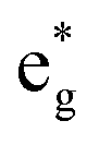 antibonding orbitals by those mainly from the Co 3d orbital, along with a nonbonding orbital t2g composed of Co 3d orbitals.67 LCO exhibits non-magnetism with t2g orbitals fully occupied by 6 electrons from Co3+, consistent with previously reported results (Fig. 5b).67 However, F ([He]2s22p5) has one extra valence electron compared to O ([He]2s22p4), while the number of bonding orbitals formed by F and Co atoms remains the same (Fig. 5a). Consequently, one of the
  antibonding orbitals is singly occupied and moves downwards in energy with F substitution, generating spin-polarization in the projected density of states (PDOS) (Fig. 5c). In LCO, when the cathode charging approaches 4.6 V, the Fermi energy level (EFermi) shifts to a lower energy state. In such a case, the bonding orbital becomes partially occupied and causes the weakening of the Co–O bond. But since there is a singly occupied anti-bonding
  orbital with F substitution, electrons get transferred from the occupied
  orbitals instead of eg orbitals, which results in the enhancement of Co–F bonds and makes Co dissolution more difficult. The spin density in Fig. S22 (ESI†) demonstrates spin polarization in the Co atom after F diffusion, in accordance with PDOS analysis. Furthermore, upon the investigation of the O loss mechanism, the migration of O species in LCO is considered to follow the so-called vacancy mechanism.18 In other words, the O species migrate by changing positions with O vacancies. The kinetics of such migration is investigated by the climbing image nudged elastic band (CI-NEB) method,39 with the diffusion path shown in Fig. S23 (ESI†). It is demonstrated that the introduction of F atoms into LCO can increase the energy barrier of oxygen migration from 0.74 to 1.09 eV (Fig. 5d). Since the dense LiF capping layer on the surface induces the formation of a LiF-rich outer CEI, this further effectively suppresses oxygen loss and cobalt dissolution. It is reasonably elucidated that these processes (Co–F enhanced by electron transfer from the occupied anti-bonding
  orbital and increased migration barrier for O atoms) work simultaneously to promote stable electrochemical properties in F-LCO at a voltage as high as 4.6 V.