
Exploring the degradation mechanism of nickel–copper–molybdenum hydrogen evolution catalysts during intermittent operation†
Shengxiong
Yang
a,
Zhihan
Liu
a,
Pengcheng
Wan
b,
Liangsheng
Liu
a,
Yimin
Sun
b,
Fei
Xiao
*a,
Shuai
Wang
*a and
Junwu
Xiao
 *a
*a
aKey Laboratory of Material Chemistry for Energy Conversion and Storage, Ministry of Education, Hubei Key Laboratory of Material Chemistry and Service Failure, Department of Chemistry and Chemical Engineering, Huazhong University of Science and Technology, Wuhan 430074, China. E-mail: xiaofei@hust.edu.cn; chmsamuel@hust.edu.cn; chjwxiao@hust.edu.cn
bHubei Key Laboratory of Plasma Chemistry and Advanced Materials School of Materials Science and Engineering, Wuhan Institute of Technology, Wuhan, 430205, China
First published on 16th November 2023
Abstract
We investigate the dynamic degradation behaviors of a nickel–copper–molybdenum hydrogen evolution catalyst in a liquid and solid polymer electrolyte to figure out its endurance in a renewable energy-driven electrolyzer. A cathode current protection approach is proposed to achieve a durable electrolyzer during intermittent operation.
Hydroxide exchange membrane electrolyzers (HEMELs) combine the merits of low cost of alkaline electrolyzers (AELs) and zero-gap configuration of proton exchange membrane electrolyzers (PEMELs).1–3 It holds great promise for achieving the Hydrogen Shot ($1 per 1 kilogram hydrogen) launched by the U.S. Department of Energy (DOE).4 However, compared to the oxygen evolution reaction, the more sluggish hydrogen evolution reaction (HER) kinetics in an alkaline environment involving water dissociation notably restrict the HEMEL performance.5 Therefore, extensive efforts have recently been devoted to designing highly active and durable precious-metal-free HER catalysts.
Nickel–molybdenum (Ni–Mo) catalysts are thought of as one of the most promising precious-metal-free HER catalysts in an alkaline environment reported to date.6 Many efforts have recently been devoted to unraveling their structural–activity relationship and attaining exceptional catalytic activity and endurance under steady state conditions through dynamic dissolution and the construction of alloy-oxide interfaces.7–10 However, the catalyst must be tolerant to intermittent fluctuating power, deliberate shutdowns and on–off cycles in a realistic scenario, which is of particular importance for green hydrogen production powered by renewable energy.11,12 In an earlier work, Divisek et al.13 reported a profound deactivation of the Ni–Mo catalyst after a power interruption, accompanied by substantially lowering the Mo amount in the catalyst. Ledendecker et al.14 found that the dissolution rate of Ni, Co, Mo and W in the current interruption period was much higher than that at HER potential. Peng et al.15 revealed that power interruption has a detrimental effect on the stability of the Ni–Mo catalyst in a three-electrode configuration. However, there are fundamental discrepancies in the chemical environment between the three-electrode configuration and HEMELs.16,17 Lee et al.18 recently found that the sudden voltage change could induce the fast deterioration of the HEMEL performance when using the Ni3Mo cathode, but it is not systematically investigated. Therefore, elucidating the effect of intermittent operation on the stability of the Ni–Mo based cathode in HEMELs is crucial for their practical application.
In this communication, we take a trimetallic nickel–copper–molybdenum (Ni–Cu–Mo) catalyst as an example and systematically study its dynamic stability performance through accelerated degradation tests (ADT) in an H-type cell and electrolyzer. In an H-type cell, the catalyst displayed a rapid activity loss during intermittent operation. The physiochemical analysis unravelled the underlying reasons for surface Mo and Ni species evolving into soluble MoO42− and stable β-Ni(OH)2 in an O2-containing environment. The catalyst deterioration is also observed in a HEMEL, but it is largely alleviated due to the difficulty in air diffusion and the use of a solid polymer electrolyte. Moreover, executing a small cathodic current at a power off interval can prevent cathode oxidation and achieve the HEMEL durability during intermittent operation comparable to continuous operation.
The Ni–Cu–Mo catalyst is synthesized through a simple precipitation and thermal reduction process.19 The HER activity is evaluated in 1.0 M KOH solution without iR correction. As shown in Fig. S1 (ESI†), the activity of the Ni–Cu–Mo catalyst reaches the summit at a molar ratio of 0.9![[thin space (1/6-em)]](https://www.rsc.org/images/entities/char_2009.gif) :0.1:1.0 with an overpotential of 36 mV at 10 mA cm−2, which surpasses those of Ni–Mo (90 mV), Cu–Mo (220 mV) and even benchmark Pt/C (20%, 43 mV) catalysts. It also shows superior durability with a negligible decay at 100 mA cm−2 for 100 hours of continuous operation (Fig. S2, ESI†). However, the catalyst degrades rapidly with increasing the idle time in 1.0 KOH solution (Fig. S3, ESI†). The similar degradation phenomenon was also observed in Ni–Mo, Cu–Mo, and self-supported NiMoOx and CoMoOx catalysts under intermittent operation (Fig. S4 and S5, ESI†). This suggests that introducing Cu species into the Ni–Mo catalyst has no influence on the durability performance. To further illustrate the stability under intermittent conditions, the Ni–Cu–Mo catalyst operates under a polarization potential of −0.17 V (vs. RHE) for 300 s followed by power-off mode for another 300 s. As displayed in Fig. 1a, compared to that in H2-saturated electrolyte, there is a notable activity loss when oxygen gas is bubbled into the electrolyte, implying that dissolved oxygen is accountable for the deterioration. It is further illustrated by a small cathodic potential executed at a power off interval inhibiting the deactivation even in oxygenated alkaline solution (Fig. S6, ESI†).
:0.1:1.0 with an overpotential of 36 mV at 10 mA cm−2, which surpasses those of Ni–Mo (90 mV), Cu–Mo (220 mV) and even benchmark Pt/C (20%, 43 mV) catalysts. It also shows superior durability with a negligible decay at 100 mA cm−2 for 100 hours of continuous operation (Fig. S2, ESI†). However, the catalyst degrades rapidly with increasing the idle time in 1.0 KOH solution (Fig. S3, ESI†). The similar degradation phenomenon was also observed in Ni–Mo, Cu–Mo, and self-supported NiMoOx and CoMoOx catalysts under intermittent operation (Fig. S4 and S5, ESI†). This suggests that introducing Cu species into the Ni–Mo catalyst has no influence on the durability performance. To further illustrate the stability under intermittent conditions, the Ni–Cu–Mo catalyst operates under a polarization potential of −0.17 V (vs. RHE) for 300 s followed by power-off mode for another 300 s. As displayed in Fig. 1a, compared to that in H2-saturated electrolyte, there is a notable activity loss when oxygen gas is bubbled into the electrolyte, implying that dissolved oxygen is accountable for the deterioration. It is further illustrated by a small cathodic potential executed at a power off interval inhibiting the deactivation even in oxygenated alkaline solution (Fig. S6, ESI†).
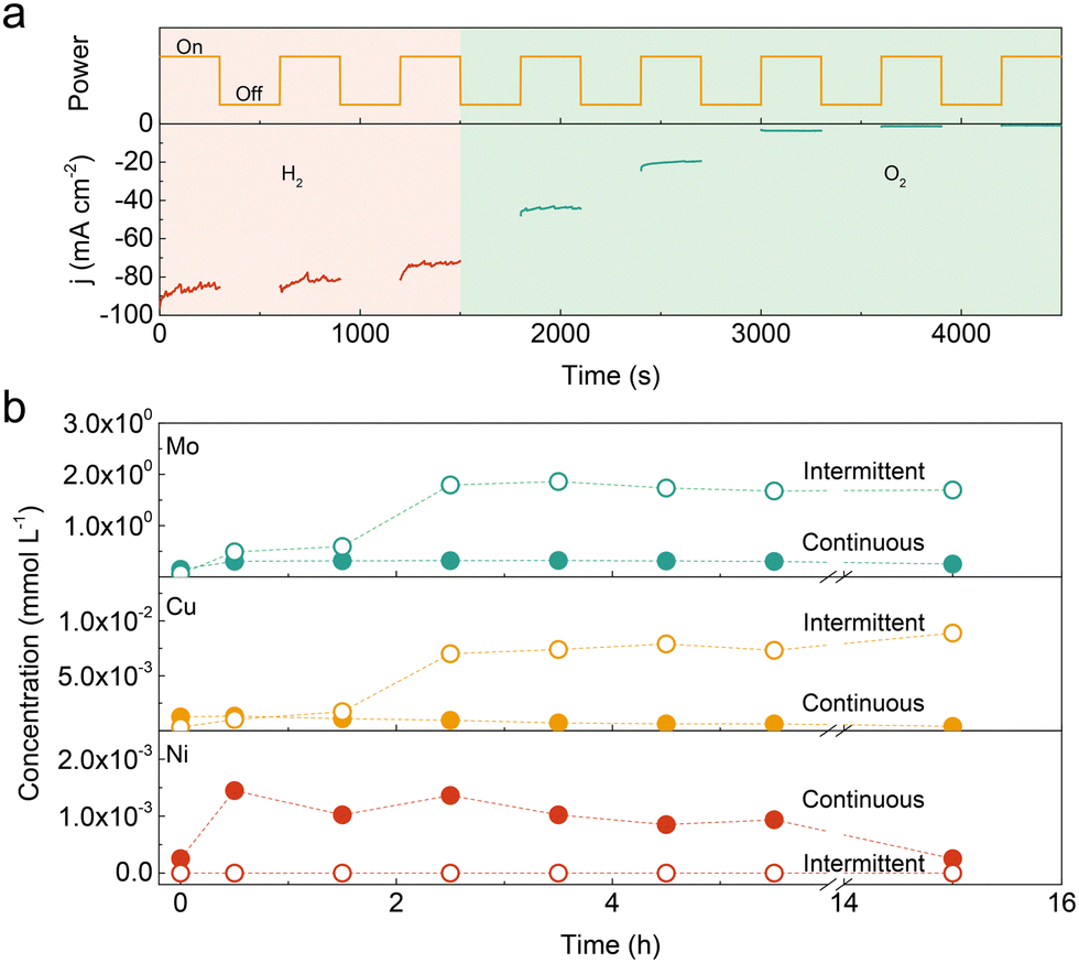 | ||
| Fig. 1 (a) Performance of the Ni–Cu–Mo catalyst in H2 or O2-containing 1.0 M KOH solution during intermittent operation. (b) Time-dependent concentration of the dissolved Ni, Cu and Mo species in the electrolyte during continuous and intermittent operations. | ||
To unravel the discrepancy during continuous and intermittent operations, the Ni, Cu and Mo contents in the electrolyte were analysed by inductively coupled plasma-optical emission spectrometer (ICP-OES). As presented in Fig. 1b, the Mo concentration was 2–3 orders of magnitude higher than Ni and Cu species in the early stage, independent of continuous and intermittent operations, probably due to thermodynamic instability in an alkaline solution.7,20 The amount of dissolved Mo is almost unchanged in continuous operation, while it increases by a factor of ∼40 after 2.5 h intermittent operation. The tendency of dissolved Cu species is similar with Mo species in continuous and intermittent operations. The Cu concentration in the electrolyte reaches the summit after 2.5 h intermittent operation, which is ∼10 times higher than that in continuous operation. Hence, it suggests that the leaching degree in the Ni–Cu–Mo catalyst is substantially higher in intermittent operation, as compared with continuous operation.
Nonetheless, no Ni species are detected in the electrolyte during intermittent operation as compared to continuous operation. It probably results from the unprecedented dissolution of Ni species at a power off interval followed by the formation of Ni(OH)2 at the catalyst surface through a dissolution–precipitation process.20,21
To further understand the degradation process, the Ni–Cu–Mo catalysts before and after the stability test were examined using transmission electron microscopy (TEM) and X-ray photoelectron spectrum (XPS) technologies. The TEM image clearly shows the solid nanocuboid structure of the Ni–Cu–Mo catalyst (Fig. 2a). The high-resolution TEM image in Fig. 2b reveals that the lattice fringes at the distance of 0.210 nm correspond to the (121) facet of MoNi4, larger than that of the Ni–Cu catalyst (Fig. S7, ESI†). This is probably ascribed to the successful doping of a bigger copper atom than nickel into MoNi4, in accordance with the diffraction peaks of MoNi4 shifting to a lower degree in the XRD patterns (Fig. S8, ESI†). Moreover, the lattice distance at 0.240 nm belongs to the (111) facet of NiO. The nanocuboid structure is well retained after continuous operation (Fig. 2d), as consolidated by scanning electron microscopy (SEM) (Fig. S9, ESI†), and the lattice fringes of NiO and MoNi4 are clearly presented in the high-resolution TEM image (Fig. 2e). This implies good durability performance of the Ni–Cu–Mo catalyst during continuous operation, in agreement with robust nickel–molybdenum catalysts reported before.22 However, the solid nanocuboids grow into hollow ones after intermittent operation, accompanying the formation of microscopic nanosheets at the surface (Fig. 2f and Fig. S9, ESI†). Fig. 2g reveals that the lattice fringes of the nanosheets at 0.265 nm belong to (100) crystal faces of β-Ni(OH)2, which agrees well with the appearance of the characteristic peaks of β-Ni(OH)2 at 2θ = 19.6°, 33.4°, and 38.8 in the XRD pattern (Fig. S8, ESI†). It is further demonstrated by the Raman spectra, where the Mo–O peaks at 344 and 935 cm−1 decline after continuous operation and totally vanish after intermittent operation (Fig. S10, ESI†). Meanwhile, the Ni–O peak at 526 cm−1 is strengthened after intermittent operation.23,24 Therefore, it discloses that, in intermittent operation, the Ni–Cu–Mo catalyst is first oxidized and leached in oxygenated alkaline solution, followed by the dissolved Ni species depositing at the surface in the formula of β-Ni(OH)2.
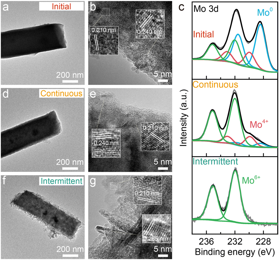 | ||
| Fig. 2 TEM (a), (d) and (f) and high-resolution TEM images (b), (e) and (g) and Mo 3d XPS spectra (c) of the Ni–Cu–Mo catalyst before and after continuous and intermittent operations in O2-containing 1.0 M KOH solution. | ||
As seen from the Ni 2p and Cu 2p XPS spectra (Fig. S11, ESI†), the surface Ni and Cu species in the Ni–Cu–Mo catalyst are readily oxidized, and more Ni2+ and Cu2+ species are formed after intermittent operation relative to continuous operation. The Mo 3d XPS signals reveal the mere existence of Mo6+ species on the surface after intermittent operation, in contrast to Mo0, Mo4+, and Mo6+ species after continuous operation (Fig. 2c). Hence, the above results confirm the oxidization of Mo0 species into Mo6+ by dissolved oxygen at a power off interval during intermittent operation, associated with metallic Ni evolving into stable β-Ni(OH)2 layered nanosheets via a dissolution–precipitation mechanism, resulting in catalyst deactivation.
Besides that in an alkaline solution, the degradation behavior of the catalyst in an alkaline polymer electrolyte was assessed by implementing the Ni–Cu–Mo cathode and our reported nickel iron anode into a HEMEL.25 The temperature of the HEMEL is set as 80 °C and the supporting electrolyte or pure water was only flowed through the anode. Fig. 3 depicts the response of the cell voltage and high frequency resistance (HFR) to current density. Note that the cell voltage progressively climbs to 1.57 V at a degradation rate of as low as 0.3 mV h−1, when the HEMEL was stably run at 500 mA cm−2 for 30 hours with the flow of 1.0 M KOH into the anode. The cell performance still approaches that of steady state operation after 5 cycles of intermittent operation at 500 and 1 mA cm−2 for 1 hour each, in association with the stable HFR. However, the voltage at 500 mA cm−2 quickly climbs to 1.59 V at a rate of 4.0 mV h−1, when it is operated intermittently between 500 and 0 mA cm−2 for another 5 cycles. Moreover, the open circuit voltage (OCV) drops immediately to 1.3 V and then gradually decreases to 0.2 V. It is most likely due to cathode oxidization at the power off interval, in line with PEMEL operated in intermittent mode.26,27 When oxygen gas is pumped into the cathode at a power off interval during intermittent operation, the HEMEL voltage at 500 mA cm−2 rises from 1.59 V to 1.73 V and the OCV drops rapidly to 0.2 V, along with a fast increase of the HFR. This further clarifies that the performance decay is due to the partial deactivation of the Ni–Cu–Mo catalyst caused by irreversible oxidation in an oxygen environment. However, in contrast to the complete deactivation after 4 hours of operating in an H-type cell, the HEMEL voltage at 500 mA cm−2 just increases by 20 mV over 10 hours of intermittent operation. This illustrates the lower deactivation degree of the Ni–Cu–Mo catalyst in a HEMEL compared to an H-type cell, which is probably attributed to solid polymer electrolyte preventing the oxygen diffusion. When being further stably operated at 500 mA cm−2 for another 90 hours, the voltage of the HEMEL slowly recovers to 1.71 V, in association with the HFR decreasing by 100 mΩ cm2, most likely due to the dissolved metal species adsorbed on the catalyst surface being to some degree reduced during operation.
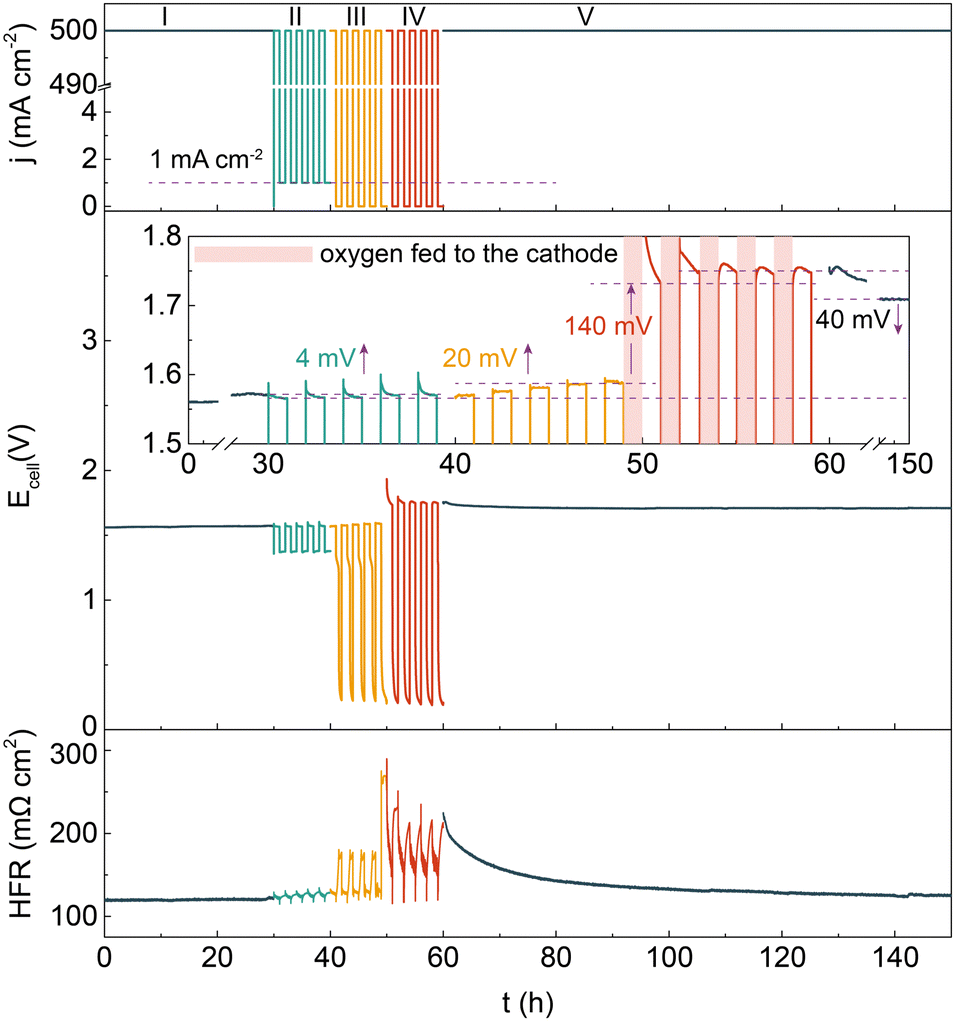 | ||
| Fig. 3 The response of the cell voltage and HFR to current density in a dynamic test at 80 °C. The test protocol with specific dynamic power supply is described as follows: (I) Continuous operation at 500 mA cm−2 for 30 hours. (II) Intermittent operation between 500 and 1 mA cm−2 for 2 hours per cycle. Intermittent operation between 500 and 0 mA cm−2 for 2 hours per cycle, without (III) and with (IV) oxygen gas pumping into the cathode at power off intervals. (V) Continuous operation at 500 mA cm−2 for 90 hours. | ||
Based on the above findings, a minimum current protection strategy is proposed to circumvent the degradation induced by intermittent operation. Fig. 4 illustrates the effect of a minimum holding current during intermittent operation. Note that the degradation rate of the HEMEL operated in intermittent mode decreases significantly by a factor of ∼40, when a low current density of 1 mA cm−2 is executed at power off intervals. The degradation rate can reach 0.1 mV h−1 with the flow of 1.0 M KOH solution into the anode, approaching that in continuous operation mode. When pure water as a replacement of 1.0 M KOH is fed into the anode, the stability performance is also improved and the degradation rate decreases from 9.4 mV h−1 to 1.8 mV h−1. This further highlights the significance of a minimum current protection performed at power off intervals.
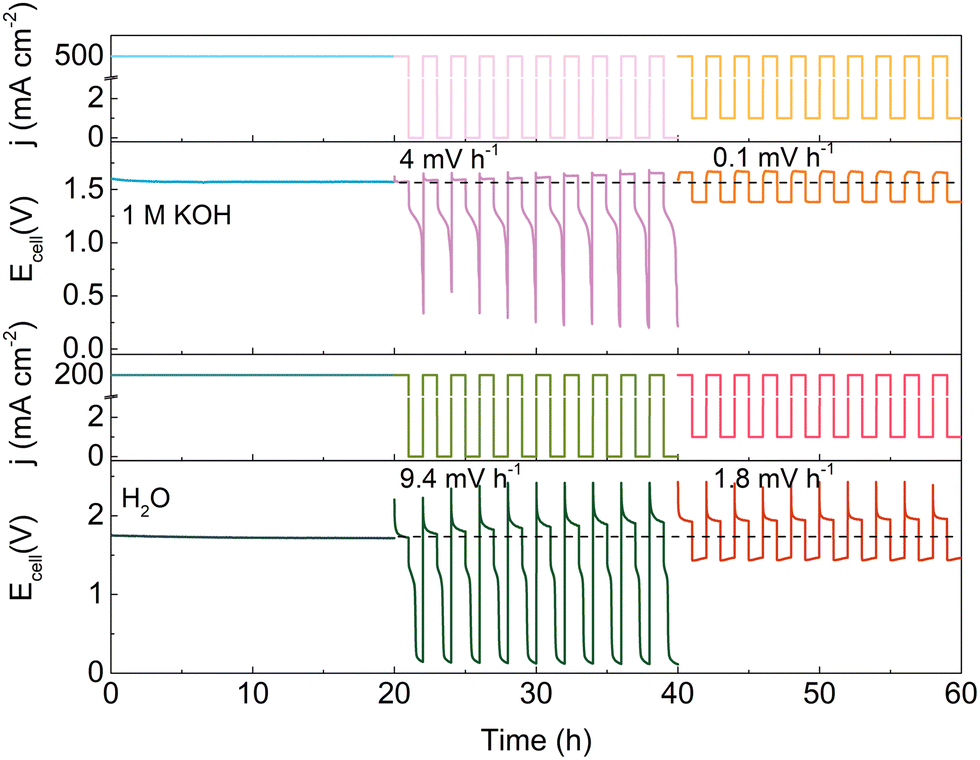 | ||
| Fig. 4 The long-term durability performance of HEMEL during intermittent operations at 80 °C with the flow of 1.0 M KOH solution (top half of panel) and pure-water into the anode (bottom half of panel). No liquid electrolyte was pumped to the cathode. | ||
In this study, we have investigated the degradation behaviours of the Ni–Cu–Mo catalyst during intermittent operation in an H-type cell and HEMEL. The surface Mo species are oxidized into soluble high valence MoO42− in O2-containing alkaline solution, in association with the surface Ni species evolving to stable β-Ni(OH)2via a dissolution–precipitation mechanism, leading to total deactivation in an H-type cell. By comparison, the deterioration in HEMEL is to a great degree relieved, since the utilization of solid polymer electrolyte prevents the oxygen diffusion. Moreover, a tiny cathodic current is conducted at power off intervals to further limit cathode catalyst oxidization, improving the intermittent durability performance close to that of continuous operation. Therefore, this work clearly demonstrates the degradation behaviours of the cathode catalyst in a liquid electrolyte and solid polymer electrolyte, and provides a simple but feasible strategy for strengthening the lifetime of the electrolyzer during intermittent operation.
Conflicts of interest
There are no conflicts to declare.Notes and references
- Y. Leng, G. Chen, A. J. Mendoza, T. B. Tighe, M. A. Hickner and C.-Y. Wang, J. Am. Chem. Soc., 2012, 134, 9054–9057 CrossRef CAS PubMed.
- J. R. Varcoe, P. Atanassov, D. R. Dekel, A. M. Herring, M. A. Hickner, P. A. Kohl, A. R. Kucernak, W. E. Mustain, K. Nijmeijer, K. Scott, T. Xu and L. Zhuang, Energy Environ. Sci., 2014, 7, 3135–3191 RSC.
- C. C. Pavel, F. Cecconi, C. Emiliani, S. Santiccioli, A. Scaffidi, S. Catanorchi and M. Comotti, Angew. Chem., Int. Ed., 2014, 53, 1378–1381 CrossRef CAS PubMed.
- B. S. Pivovar, M. F. Ruth, D. J. Myers and H. N. Dinh, Electrochem. Soc. Interface, 2021, 30, 61 CrossRef.
- J. Durst, A. Siebel, C. Simon, F. Hasché, J. Herranz and H. A. Gasteiger, Energy Environ. Sci., 2014, 7, 2255–2260 RSC.
- C. C. L. McCrory, S. Jung, I. M. Ferrer, S. M. Chatman, J. C. Peters and T. F. Jaramillo, J. Am. Chem. Soc., 2015, 137, 4347–4357 CrossRef CAS.
- W. Du, Y. Shi, W. Zhou, Y. Yu and B. Zhang, Angew. Chem., Int. Ed., 2021, 60, 7051–7055 CrossRef CAS PubMed.
- M. Schalenbach, F. D. Speck, M. Ledendecker, O. Kasian, D. Goehl, A. M. Mingers, B. Breitbach, H. Springer, S. Cherevko and K. J. J. Mayrhofer, Electrochim. Acta, 2018, 259, 1154–1161 CrossRef CAS.
- R. B. Patil, S. D. House, A. Mantri, J. C. Yang and J. R. McKone, ACS Catal., 2020, 10, 10390–10398 CrossRef CAS.
- X. Shi, X. Zheng, H. Wang, H. Zhang, M. Qin, B. Lin, M. Qi, S. Mao, H. Ning, R. Yang, L. Xi and Y. Wang, Adv. Funct. Mater., 2023, 33, 2307109 CrossRef CAS.
- H. Kojima, K. Nagasawa, N. Todoroki, Y. Ito, T. Matsui and R. Nakajima, Int. J. Hydrogen Energy, 2023, 48, 4572–4593 CrossRef CAS.
- S. Siracusano, S. Trocino, N. Briguglio, F. Pantò and A. S. Aricò, J. Power Sources, 2020, 468, 228390 CrossRef CAS.
- J. Divisek, H. Schmitz and J. Balej, J. Appl. Electrochem., 1989, 19, 519–530 CrossRef CAS.
- M. Ledendecker, J. S. Mondschein, O. Kasian, S. Geiger, D. Göhl, M. Schalenbach, A. Zeradjanin, S. Cherevko, R. E. Schaak and K. Mayrhofer, Angew. Chem., Int. Ed., 2017, 56, 9767–9771 CrossRef CAS.
- L. Peng, J. Min, A. Bendavid, D. Chu, X. Lu, R. Amal and Z. Han, ACS Appl. Mater. Interfaces, 2022, 14, 40822–40833 CrossRef CAS PubMed.
- T. Lazaridis, B. M. Stühmeier, H. A. Gasteiger and H. A. El-Sayed, Nat. Catal., 2022, 5, 363–373 CrossRef CAS.
- M. F. Lagadec and A. Grimaud, Nat. Mater., 2020, 19, 1140–1150 CrossRef CAS.
- W. Lee, H. Yun, Y. Kim, S. S. Jeon, H. T. Chung, B. Han and H. Lee, ACS Catal., 2023, 13, 11589–11597 CrossRef CAS.
- J. R. McKone, B. F. Sadtler, C. A. Werlang, N. S. Lewis and H. B. Gray, ACS Catal., 2013, 3, 166–169 CrossRef CAS.
- E. S. Davydova, F. D. Speck, M. T. Y. Paul, D. R. Dekel and S. Cherevko, ACS Catal., 2019, 9, 6837–6845 CrossRef CAS.
- F. D. Speck, A. Zagalskaya, V. Alexandrov and S. Cherevko, Angew. Chem., Int. Ed., 2021, 60, 13343–13349 CrossRef CAS PubMed.
- M. Wang, H. Yang, J. Shi, Y. Chen, Y. Zhou, L. Wang, S. Di, X. Zhao, J. Zhong, T. Cheng, W. Zhou and Y. Li, Angew. Chem., Int. Ed., 2021, 60, 5771–5777 CrossRef CAS PubMed.
- J.-Y. Zhang, J. Liang, B. Mei, K. Lan, L. Zu, T. Zhao, Y. Ma, Y. Chen, Z. Lv, Y. Yang, C. Yu, Z. Xu, B. Y. Xia, W. Li, Q. Yuan and D. Zhao, Adv. Energy Mater., 2022, 12, 2200001 CrossRef CAS.
- Y. Wang, S. Gai, N. Niu, F. He and P. Yang, J. Mater. Chem. A, 2013, 1, 9083–9091 RSC.
- J. Xiao, A. M. Oliveira, L. Wang, Y. Zhao, T. Wang, J. Wang, B. P. Setzler and Y. Yan, ACS Catal., 2021, 11, 264–270 CrossRef CAS.
- E. Brightman, J. Dodwell, N. van Dijk and G. Hinds, Electrochem. Commun., 2015, 52, 1–4 CrossRef CAS.
- A. Weiß, A. Siebel, M. Bernt, T. H. Shen, V. Tileli and H. A. Gasteiger, J. Electrochem. Soc., 2019, 166, F487–F497 CrossRef.
Footnote |
| † Electronic supplementary information (ESI) available: Details of the experimental methods and figures. See DOI: https://doi.org/10.1039/d3cc04867e |
| This journal is © The Royal Society of Chemistry 2024 |