
 Open Access Article
 This Open Access Article is licensed under a Creative Commons Attribution-Non Commercial 3.0 Unported Licence
Compositionally variant bimetallic Cu–Mn oxysulfide electrodes with meritorious supercapacitive performance and high energy density†
Heba M.
El Sharkawy
a,
Abdussalam M.
Elbanna‡
 b,
Ghada E.
Khedr‡
a and
Nageh K.
Allam
*b
b,
Ghada E.
Khedr‡
a and
Nageh K.
Allam
*b
aDepartment of Analysis and Evaluation, Egyptian Petroleum Research Institute, Cairo, 11727, Egypt. E-mail: nageh.allam@aucegypt.edu
bEnergy Materials Laboratory, School of Sciences & Engineering, The American University in Cairo, Cairo, 11835, Egypt
First published on 9th October 2023
Abstract
Rational design and fabrication of low-cost, earth-abundant electrode materials for energy conversion and storage devices is immensely needed. Herein, we demonstrate the successful fabrication of Cu–Mn mixed-metallic oxysulfides (Cu–Mn–OS) and their use as supercapacitor electrodes, benefiting from the integrated advantages of both oxides and sulfides as well as the combined contribution from both Cu and Mn elements. In particular, the C3M1OS electrode performs exceptionally well in a three-electrode system, revealing a very high capacity of 1525.1 C g−1 (3177.2 F g−1) at a current density of 1 A g−1. Moreover, using commercial activated carbon (AC) as the negative pole and a C3M1OS electrode as the positive pole, the fabricated asymmetric supercapacitor device (C3M1OS//AC) exhibits a very high energy density of 76.56 W h kg−1 along with a power density of 985.01 W kg−1 at 1 A g−1 with superior electrochemical stability and efficiency over 10![[thin space (1/6-em)]](https://www.rsc.org/images/entities/char_2009.gif) 000 cycles. The current work not only proposes a straightforward, single-step strategy for the fabrication of mixed-metallic oxysulfide electrodes but also establishes a new avenue for the fabrication of a standout candidate electrode for energy storage devices with a distinctive specific energy.
000 cycles. The current work not only proposes a straightforward, single-step strategy for the fabrication of mixed-metallic oxysulfide electrodes but also establishes a new avenue for the fabrication of a standout candidate electrode for energy storage devices with a distinctive specific energy.
Introduction
Access to renewable energy should have a tremendously positive impact on humanity's future. The world is dedicating a plethora of efforts to the development of sustainable alternative energy sources to tolerate the catastrophic consequences of the depletion of fossil fuels, environmental pollution, and the severe increase in energy demand. In this respect, energy storage devices play an essential complementary role in realizing sustainable energy systems. Supercapacitors (SCs) have distinguished characteristics, such as the ability to charge quickly, high specific power, secure operation, reasonable maintenance, and a well-extended lifetime and operating temperature, which make them a prominent class of energy storage systems. However, they still have lower energy density than rechargeable batteries.1–3The energy density of supercapacitors can be enhanced via two pathways: expanding the cell working voltage by using asymmetric supercapacitor devices and/or the proper choice of electrode materials. In this regard, nanostructured materials containing mixed metals and anions have been shown to outperform the conventional counterpart materials in terms of electrochemical performance and durability. Specifically, transition metal oxysulfides (TMOS) have been suggested as promising electrode materials for energy storage devices owing to their comparatively high specific capacitance and cycling stability.4–15 Note that transition metal oxides (TMO) still suffer from some constraints of limited electrical conductivity and moderate cycling life despite their multivalence states, low cost, and high specific capacitance. At a current density of 1 A g−1, the CuMnO2/GQD nanocomposite and CuMnO2 nanoparticles exhibited capacities of 520.2 and 381.5 C g−1,16 respectively. CuMn2O4–RGO, however, delivered a specific capacitance (Csp) of 342 F g−1.17
On the other hand, it is worth noting that transition metal sulfides (TMS) have been shown to have greater thermal and mechanical stability, electrical conductivity, and electrochemical performance than their metal oxide counterparts.18–23 However, the sluggish reaction kinetics affected their electrochemical performance. At 2 A g−1, neuron-like hierarchical core–shell manganese sulfide@Cu2S (MCS) arrays achieved a Csp of 2270.1 F g−124 and the flower-like Cu–Mn bimetallic sulfide on Ni-foam (CuS/MnS@NF) showed a Csp of 1517.07 F g−1 at 1 A g−1.25
Interestingly, it is envisaged that the exchange of some of the oxygen anions with sulfur anions would efficiently tune the electrical and electrochemical properties, allowing the morphology of the resulting material to be more flexible. As a result, the morphology can accommodate possible changes in volume that may occur during the charging/discharging process due to the fact that sulfur has lower electronegativity than oxygen. However, there are a few reports on TMOS-based electrodes for supercapacitors. For example, the hydrothermally synthesized cobalt–nickel oxysulfide showed a Csp of 592 F g−1 at 0.5 A g−1 with a cycling stability of 95.8% after 2000 cycles.8 In another work, manganese–cobalt oxysulfide nanoflowers grown on the Ni foam exhibited a Csp of 490 C g−1 at 2 A g−1 with a capacitance retention of 86.5% after 3000 cycles.9 Additionally, manganese oxysulfide nanofibers grown on a Ti substrate showed Csp of 214 F g−1 at 1 mA cm−2 and a recyclability of 75.4% over 1000 cycles.10 Moreover, at a current density of 1 A g−1, zinc–cobalt oxysulfide had a Csp of 645.5 C g−1 with a capacity retention of 76% after 1000 cycles.11 Besides, flower-like Cu0.33Co0.67OxSy nanosheets provided a high Csp of 193 mA h cm−2 (443.9 μA h cm−2) at 3 mA cm−2.12 A composite of nickel–molybdenum oxyphosphides and oxysulfides (NMOP/NMOS) delivered a Csp of 338.7 F g−1.13 Electrodeposited iron–vanadium oxysulfide (Fe–VO–S) nanostructures on the SS substrate with an Fe:VO molar ratio of 2:1 showed a Csp of 217 F g−1 at 3 A g−1.14
The above studies revealed the importance of the proper choice not only of the elements but also of their redox chemistry to achieve the desired performance. In this regard, Mn and Cu are two essential transition metal elements with strong electrochemical activity, low cost, availability in nature, and ecological compatibility. Although Mn has multiple oxidation states ranging from +2 to +7, its performance in supercapacitors may not be satisfactory primarily due to structural damage during electrochemical measurements. In contrast, Cu has great electrical conductivity (Eg = 1.2 to 2.0 eV), which should guarantee outstanding capacitance performance.26 Thus, a composite of these two elements (Cu and Mn) should ensure that the properties are ameliorated, leading to an outstanding electrochemical performance as a supercapacitor electrode.
Therefore, herein, we demonstrate the capability to optimize the synthesis of copper–manganese oxysulfide (Cu–Mn–OS) nanostructures on a Ni foam substrate via a simple, low-temperature, and cost-effective wet chemistry method that has rarely been reported. The Cu–Mn–OS nanostructures were prepared with different Cu:Mn molar ratios of 3:1, 1:1, and 1:3, namely (C3M1OS, C1M1OS, C1M3OS), where their oxysulfide form has not been investigated compared to their oxide and sulfide counterparts. Electrochemical techniques such as cyclic voltammetry (CV), galvanostatic charge–discharge (GCD), and electrochemical impedance spectroscopy (EIS) were used to compare the electrochemical performance of as-fabricated composites with varied Cu:Mn molar ratios. Also, density functional theory (DFT) calculations were executed to scrutinize the electronic properties of oxysulfide structures, as DFT was proven to be a robust tool in examining the electronic properties.27–32 To unveil the real functionality of the C3M1OS electrode, an asymmetric device was assembled employing commercial activated carbon (AC) as the negative pole and C3M1OS as the positive pole, with a weight of ∼4 mg, i.e., commercial mass loading. The assembled device provided a very high energy density of 76.56 W h kg−1 along with a power density of 985.01 W kg−1 at 1 A g−1 with superior electrochemical stability and efficiency over 10000 charge/discharge cycles.
Experimental section
Materials synthesis
A simple and low-cost wet chemistry method was employed to synthesize copper–manganese binary oxysulfides (Cu–Mn–OS). Briefly, 2.5 mmol of Cu(NO3)2·3H2O were added to 2.5 mmol of Mncl2·4H2O and dissolved in 25 ml of distilled water with stirring for 30 min to prepare solution A. Subsequently, another 25 ml of distilled water was used to dissolve 1.3 mmol of Na2S·1H2O to form solution B. Then, solution B was added dropwise to solution A. For 30 minutes, the produced mixture was gradually heated at around 80 °C. Then, a clean slice of Ni-foam (NF) as a substrate was inserted in the above mixture and was left for 1 h to allow the growth and deposition of Cu–Mn–OS directly on the Ni-foam substrate. Finally, after removing the electrode from the reaction solution, followed by rising many times with distilled water to remove any loosely bound particles from the electrode surface and drying at 60 °C for 12 h in a vacuum oven, the Cu–Mn–OS @NF electrode was obtained. Additionally, to investigate the effect of varying the copper and manganese concentrations in the resultant composite, different ratios were prepared by varying the precursor concentration solution, copper and manganese (1:3, 1:1 and 3:1) and using the same preparation method, which was labelled (C1M3OS, C1M1OS, and C3M1OS), according to the Cu and Mn ratio, see Scheme 1.
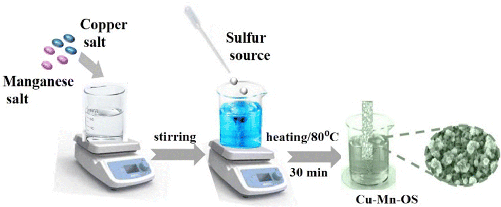 | ||
| Scheme 1 Schematic of the stepwise synthesis of the Cu–Mn–OS@NF electrodes. | ||
Materials characterization
Several techniques were used to characterize the prepared nanostructures, where a PANalytical X’Pert PRO X-ray diffractometer (XRD) with Cu Kα (λ = 15406 Å) radiation was employed to explore their structural properties. Furthermore, the surface morphology and elemental composition of the synthesized material were investigated using a Zeiss Ultra 60 FESEM attached with an energy-dispersive X-ray spectroscope (EDX). As for surface functional groups and bonds, an ATI Unicam FTIR bench-top spectrometer was used. In addition, the chemical composition and valence states of the prepared nanostructures were elucidated using a Thermo-Fisher Scientific X-ray photoelectron spectroscope, associated with monochromatic X-ray Al K-alpha radiation (10–1350 eV spot size 400 μm at a pressure of 10−9 mbar with a full spectrum pass energy of 200 eV and a narrow spectrum pass energy of 50 eV).
Computational details
Density functional theory (DFT) calculations were performed utilizing the CASTEP code implemented in Material Studio 2017. Spin-polarized calculations were done to optimize geometries and to investigate the electronic properties using the hybrid functional (HSE06), which was more adapted for electronic property simulation. The norm-conserving pseudopotential and electronic minimizer of all bands/EDFT were utilized. The cutoff energy for all calculations was 800 eV with k-points of 4 × 4 × 2 and energy convergence of 5 × 10⁻⁶ eV. We began with a LaCuOS unit cell with a tetragonal P4/nmm space group (no. 129) from the materials project website, and then substitute with Cu1Mn3OS (C1M3OS), Cu1Mn1OS (C1M1OS) and Cu3Mn1OS (C3M1OS).Electrochemical evaluation
The electrochemical performance of the fabricated Cu–Mn–OS electrodes on the Ni-foam was assessed via a Biologic SP 300 electrochemical workstation in a three- and two-electrode electrochemical setup. The binder-free Cu–Mn–OS electrodes (C1M3OS, C1M1OS, and C3M1OS) used as working electrodes, Hg/HgO as a reference electrode, and Ti mesh as a counter electrode immersed in 2 M KOH are the components of the three-electrode configuration. Galvanostatic charge/discharge (GCD) and cyclic voltammetry (CV) measurements were carried out at various scan rates and current densities, respectively, in the potential window from 0 to 0.5 V. The electrochemical impedance spectroscopy (EIS) measurements were performed at open circuit potential. The specific capacitance of the electrodes at various scan rates and current densities were calculated using eqn (1) and (2) based on the cyclic voltammograms and the galvanic charge and discharge results, respectively.33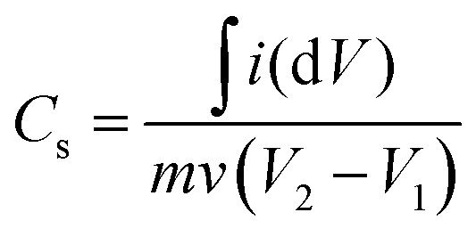 | (1) |
The integral form of  was applied to calculate the specific capacitance owing to the nonlinearity of the discharge curve profile34,35
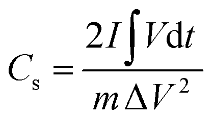 | (2) |
The specific capacity (C, C g−1) can be obtained using eqn (3).36
| C = Cs × ΔV | (3) |
 represents the area under the discharge curve, m (g) refers to the mass of the active material, and ΔV (V) refers to the operating potential window.
Fabrication of C3M1OS//AC asymmetric supercapacitor devices
The best performing electrode (C3M1OS) was used as the positive electrode, commercially activated carbon (AC) as the negative electrode, and filter paper as a spacer between two electrodes in a two-electrode configuration. As for the negative electrode, a mixture of 90% activated carbon, 10% PVDF, and N,N-dimethyl formamide as a solvent was left under stirring for 24 h to form a homogeneous ink. This ink was painted on a clean graphite sheet. The energy density (E, W h kg−1) and power density (P, W kg−1) delivered by the constructed asymmetric supercapacitor device were calculated using eqn (4) and (5) based on the GCD measurements.37,38 | (4) |
 | (5) |
Results and discussion
A wet chemical route was adopted to optimize the synthesis of copper–manganese oxysulfide (Cu–Mn–OS) nanostructures directly on the Ni foam substrate by using Cu(NO3)2·3H2O and Mncl2·4H2O as the salt precursors and Na2S·H2O as the sulfur source. The electrode is free of any binders, which ensures good conductivity and increases its active sites. The XRD spectra of the synthesized samples were recorded to elucidate their crystal structure and phase variation. Fig. 1(a) and Fig. S1 (ESI†) show the XRD spectra of the synthesized electrodes with various Cu and Mn precursor ratios. The sharp diffraction peaks reveal the good crystallinity of the prepared samples.39 All samples showed diffraction peaks of Mn2O3 at 16.2° and 18.6°, indexed well with the (111) and (002) planes, respectively (JCDPDS#01-073-1826), and peaks at 46.1° and 68.3°, which correspond to the (321) and (202) planes of MnO2 (JCDPDS#00-044-0141), respectively.40,41 Also, the Mn3O4 peak was observed only in C3M1OS and C1M3OS at 17.6°, which matches the (101) plane (JCPDS #00-024-0734).42 Furthermore, the characteristic peaks of monoclinic CuO were noticed at 35.6°, 50.3°, and 56.7°, corresponding to the (11−1), (112), and (021) planes, respectively, in the spectra of the three samples (JCPDS #00-048-1548).43 Additionally, diffraction peaks corresponding to spinel Cu1.5Mn1.5O4 (JCPDS #70-0260) and CuMn2O4 (JCPDS #00-010-0365) were cleared at 2θ of 18.6°, 30.5°, and 31.3° compatible with (111), (220), and (002) planes, respectively.41,44 Moreover, the peaks located at 31.7°, 44.3°, 47.7°, and 59.3° are characteristic of the (103), (008), (107), and (116) planes of hexagonal covellite CuS (JCPDS #00-06-0464).45 Besides, MnS peaks were detected at 25.6°, 39.1°, 50.1°, and 53.1°, corresponding to (100), (102), (103), and (200) planes (JCPDS#00-40-1289).46–49 No additional peaks are detected, suggesting that the prepared electrode material is quite pure. Furthermore, the C3M1OS sample shows the highest intensity of CuS and MnS peaks, which may reveal its higher crystallinity than the other counterpart samples.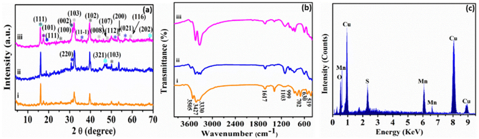 | ||
| Fig. 1 (a) XRD and (b) FTIR patterns of (i) C1M3OS, (ii) C1M1OS, and (iii) C3M1OS, and (c) the EDX spectrum of the C3M1OS nanocomposite. | ||
In order to provide a better understanding of the nature of bonding within the prepared material, FTIR measurements were conducted over the range of 4000–400 cm−1. Fig. 1(b) elucidates the FTIR spectra of our electrode material. The bands at about 519 and 702 cm−1 can be assigned to the vibrations of Mn–O.50,51 Also, the spectra showed the absorption bands at 1617 and 3330–3505 cm−1, which are attributed to –OH bending and stretching vibrations.52 Moreover, the absorption band observed at 630 cm−1 corresponds to Mn–S stretching vibrations.52 Notably, the existence of bands at 999 cm−1 designates the modes of bending vibration of Cu–O.53
Furthermore, the stretching vibration peak of the Cu–S group was detected at 1103 cm−1, which refers to the formation of Cu–S crystals.54 Hence, the FTIR results emphasized the formation of Mn–S, Cu–S, Mn–O, and Cu–O bonds on the surface of the synthesized electrode material. The peaks associated with Cu, Mn, S, and O are visible in the energy-dispersive X-ray spectroscopy (EDX) spectrum, as illustrated in Fig. 1(c). This demonstrates that C3M1OS has been successfully synthesized without any contaminants.
The fabricated C1M1OS, C1M3OS, and C3M1OS composites were analysed using FESEM with high and low magnification top-view images, as shown in Fig. 2. The C1M1OS sample displays an uneven or distorted polyhedral morphology with a homogeneous distribution, Fig. 2(a) and (b). However, in the case of C1M3OS, a nanocube-like structure is observed along with some aggregates that may be due to the increased amount of Mn in the synthesized electrode material, Fig. 2(c) and (d). Interestingly, Fig. 2(e) and (f) illustrates a nanocube-like structure covered with nanoneedles with good uniformity and gaps between the constituent particles for the C3M1OS sample, which is beneficial in facilitating the permeation of the electrolyte and offering more accessible active sites for ion diffusion and charge transfer. The homogenous distribution of Cu, Mn, S, and O elements within the developed nanostructure is also disclosed via EDX mapping, Fig. 2(g).
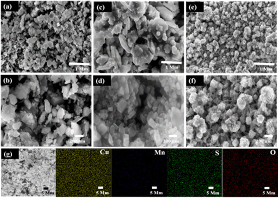 | ||
| Fig. 2 High and low magnification field-emission scanning electron microscopy (FESEM) images of the prepared (a) and (b) C1M1OS, (c) and (d) C1M3OS, and (e) and (f) C3M1OS materials, and the corresponding (g) elemental mapping of C3M1OS. | ||
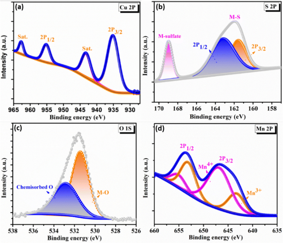
To elucidate the surface electronic states and chemical composition of the synthesized C3M1OS electrode, the X-ray photoelectron spectra (XPS) have been recorded. The binding energy peaks for Cu, Co, O, and S congruent with the EDX results are seen in the XPS survey spectrum, Fig. S2 (ESI†). The high-resolution XPS spectra of Cu 2p, Mn 2p, O 1s, and S 2p are shown in Fig. 3. The Cu 2p spectra (Fig. 3(a)) have two primary distinctive doublet peaks Cu 2p3/2 and Cu 2p1/2 at 935 and 955 eV, respectively.55 with a spin–orbit splitting of about 20 eV. In addition, two further significant satellite peaks at 943.3 and 962.8 eV were also observed.56,57 This indicates that the sample contains an unfilled Cu 3d9 shell and confirms that the Cu 2p peaks were associated with the Cu2+ oxidation state in the crystal structure, in agreement with our XRD results. Furthermore, Fig. 3(d) presents the photoelectron spectra of Mn 2p, where the doublet main peaks Mn 2p3/2 and Mn 2p1/2 were centered at 643.5 and 654.1 eV, respectively. All overlapping Mn 2p3/2 and Mn 2p1/2 signal were deconvoluted into two peaks at 643.1, 646.8, 653.5, and 655.3 eV, which are typical of Mn3+ and Mn4+ species, respectively, with a minor shift.58–60 The shift of the binding energy in the XPS spectra reflects the intense interaction between composite components.25 Additionally, the high-resolution O 1s spectra show a conspicuous peak that can be split into two peaks at binding energies of 531.4 and 533.8 eV (Fig. 3(c)), which are ascribed to the metal–oxygen bond (M–O), and adsorbed oxygen containing species (such as H2O, O2, and CO2), respectively.2,61 However, the two well-resolved spin peaks in the high resolution XPS spectrum of S 2p (Fig. 3(d)) revealed the presence of oxidized sulfur species adsorbed on the surface in the form of sulfates and hydrogen sulfates through the peak located at 168.8 eV. The other peak positioned at 162 eV is deconvoluted into two peaks at 161.5 and 163 eV, corresponding to S 2p3/2 and S 2p1/2, respectively. These peaks guarantee the presence of metal sulfur linkages (Cu–S and Mn–S bonds) and sulfur ions with low coordination numbers.62–65
 | ||
| Fig. 3 X-ray photoelectron spectroscopy spectra of C3M1OS: high resolution-XPS spectra of (a) Cu 2p, (b) S 2p, (c) O 1s, and (d) Mn 2p. | ||
The electrochemical performance of the prepared C1M3OS, C1M1OS, and C3M1OS electrodes with different ratios of manganese and copper (1:3, 1:1, and 3:1) was assessed through cyclic voltammetry (CV), galvanostatic charge/discharge (GCD), and electrochemical impedance spectroscopy (EIS) tests. Consequently, the electrochemical measurements were done in a traditional three-electrode configuration in a 2 M KOH electrolyte using Hg/HgO and Ti mesh as the reference and counter electrodes, respectively. Fig. 4(a) illustrates the cyclic voltammograms (CVs) at a fixed scan rate of 20 mV s−1 within the potential window of 0–0.5 V. The CV curves display well defined redox peaks, signifying the faradaic performance of the prepared electrodes. This is due to the reaction between KOH and the fabricated oxysulfide electrodes, which undergo the following redox transitions: Cu+/Cu2+ and Mn3+/Mn4+ states according to eqn (6)–(8).33,66–68 The redox reaction mechanism of metal sulfides is similar to that of metal oxides in an alkaline electrolyte as the oxygen and sulfur elements are in the same group in the periodic table.69
| Cu2O + 2OH− ↔ 2CuO + H2O + e− | (6) |
| Mn(OH)2 + OH− ↔ MnOOH + H2O + e− | (7) |
| MnOOH + OH− ↔ MnO2 + H2O + e− | (8) |
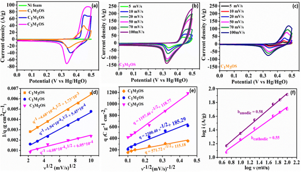 | ||
| Fig. 4 Three-electrode electrochemical measurements: (a) CV profiles at a sweep rate of 20 mV s−1 for C1M3OS, C1M1OS, and C3M1OS electrodes, (b) and (c) CV profiles of C3M1OS and C1M3OS at various scan rates (5–100 mV s−1), (d) 1/q versus v1/2 and (e) q versus v−1/2 plots for C1M3OS, C1M1OS, and C3M1OS electrodes in 2 M KOH, and (f) dependence of the cathodic and anodic currents on the scan rate for C3M1OS. | ||
Interestingly, the CVs exhibit incredible electrochemical performance as supercapacitive electrodes, owing to the inclusion of both O and S atoms in the fabricated electrodes that improve the conductivity, electrochemical active sites, and effective electron transfer capability of the material. Additionally, the capacitance contribution from the nickel foam (substrate) is too small and can be negligible. Notably, the C3M1OS electrode shows the highest current and largest area under the CV graph. The variation of the Cu:Mn atomic ratio has a significant influence on the electrochemical performance of the prepared electrodes. In order to further verify the significant electrochemical performance of the fabricated electrodes, the CV plots as a function of scan rate (5–100 mV s−1) were recorded, as depicted in Fig. 4(b), (c) and Fig. S3a (ESI†). The Cu–Mn–OS electrodes retained the same CV shape with a slight deviation in the position of the cathodic and anodic peaks, especially at high scan rates. At a high sweep rate, electrolyte ions do not have sufficient time to diffuse into the inner surface of the active material, resulting in quasi reversible electrochemical reactions at the electrode surface.
Moreover, the absence of parasitic reactions, such as oxygen evolution, indicates a suitable operating potential window with good reversibility.70–72 Furthermore, the number of electrochemical active sites (n) is calculated at a scan rate of 20 mV s−1 using the relationship n = Q/2F based on voltammetric charge density (Q) and Faraday's constant (F = 96485 C mol−1).37,73,74 The C3M1OS electrode demonstrated 3.5 mmol g−1 of active sites, while C1M1OS and C1M3OS electrodes exhibited 2.4 and 1.5 mmol g−1, respectively. This is in line with the calculated electrochemical active surface area (ECSA), which confirms the superior activity of the fabricated composites and the outstanding electrochemical performance of the C3M1OS electrode, in agreement with the CV and GCD results.
To elucidate the charge storage mechanism in the synthesized materials (Fig. 4(f) and Fig. S3b, c, S4a–f, ESI†), the power law relationship: i = aνb, where ν is the scan rate, i is the current, and a and b are adjustable values, respectively, was tested. Accordingly, the slope of the logi versus logν plot (b) determines the charge storage mechanism. While an a (b) value of 0.5 indicates a diffusion-controlled (pseudo or faradaic behavior) charge storage mechanism, and a (b) value of 1 reveals a surface-controlled process. The estimated b value for the anodic and cathodic peaks is found to be 0.58 and 0.55, respectively, indicating a diffusion-controlled mechanism that reveals the origin of the observed redox peaks.38,75,76 Moreover, the Trasatti method is used to precisely elucidate and quantify the capacitive and diffusion contributions to the charge storage mechanism. Based on the diffusion law: q(ν) = qc + k × ν−1/2, where q(ν) is the overall charge, qc is the surface-confined process charge, and k × ν−1/2 is the diffusion-controlled process charge. At scan rates approaching 0 mV s−1, the total specific capacitance (CT) can be estimated by plotting (1/q) versus (v1/2), where the charges can access the entire electrode surface as well as its interior regions. However, at high scan rates v →∞, where only the outer surface of the electrode is accessible for the charges, the double layer (Cdl) contribution can be estimated. The Cdl can be evaluated from the plot of (q) versus (v−1/2). As a result, the faradaic contribution (Cf) can be estimated from the difference between qT and qdl, as shown in Fig. 4(d) and (e). Accordingly, the faradaic process is the dominant storage mechanism for the prepared Cu–Mn–OS electrodes, where ∼93% of the total capacity originates from diffusion-controlled processes (Cf), and only 7% originates from surface-confined processes (Cdl) for the C3M1OS electrode. On the other side, the C1M1OS and C1M3OS electrodes displayed a (Cf) contribution of (∼90, 80%) and Cdl of (∼10, 20%), respectively, indicating the predominance of the diffusion-controlled process on the electrode surface.77,78 This high contribution from diffusion-controlled reactions can be attributed to the direct deposition of the active material on the substrate, which enables good electrolyte accessibility and thus enhances the electrochemical activity of the material. This is also consistent with the calculated high number of electrochemically active sites for those electrodes. It can be concluded that the coexistence of Cu and Mn in appropriate ratios along with the presence of both O and S in the composite improves the conductivity of the electrode and tunability of the nanostructures formed, and has an effective role in the electrochemical performance of the electrode.79,80
Similarly, the GCD graphs of the C1M3OS, C1M1OS, and C3M1OS electrodes reveal typical faradaic behavior with excellent symmetric charging/discharging characteristics, indicating superior reversibility of the fabricated composites. Among the tested electrodes, C3M1OS displays the longest discharge time with the highest specific capacitance. The specific capacitance of C1M3OS, C1M1OS, and C3M1OS electrodes at a constant potential window (0.48 V) and current density (1 A g−1) are 533.9, 1258.1, and 3177.2 F g−1 (256.3, 603.9, and 1525.1 C g−1), respectively, as depicted in Fig. 5(a) and (b). This superb electrochemical performance could be attributed to the incorporation of sulfur atoms with a lower electronegativity than that of oxygen into the matrix of metal oxide, which significantly enhances the electrical conductivity as well as the fast transportation of charges and the synergistic effect between two binary metals. Furthermore, the suitable and effective atomic ratio of Cu:Mn in the nanocomposite is key in determining the electrochemical capacitive performance of the material. When the amount of manganese increases, the specific capacitance decreases, which may be attributed to the mechanical expansion of MnO2, despite the high theoretical specific capacitance of Mn.9,13,25,67 Galvanostatic charge–discharge profiles (GCDs) were also recorded to assess the electrochemical performance of the C3M1OS, C1M1OS, and C1M3OS electrodes as a function of current density (1–10 A g−1) at a constant potential window of 0.48 V, Fig. 5(c)–(e). The tested electrodes displayed nonlinear charge/discharge curves with symmetry even at high current density, demonstrating the electrode's faradaic behavior with fast electron transportation from the active material to the current collector, excellent reversibility and superior performance of the fabricated composites.81 The C3M1OS electrode showed a remarkable specific capacitance of 3177.2, 2582, 2483.4, 2310.5, 2008.4, and 1682.7 F g−1 (1525, 1239, 1192, 1109, 964, and 808 C g−1) at current densities of 1, 2, 3, 5, 7, and 10 A g−1, respectively, Fig. S3d (ESI†). C3M1OS acquired higher specific capacitance than the corresponding metal sulfide and oxide counterparts, Table 1.25,26,82–90 Additionally, the electrochemical performance of the best electrode is compared with that of the MnOS (C0M4OS) and CuOS (C4M0OS), Fig. S5 and S6(a)–(c) (ESI†). Fig. 5(f) demonstrates the electrochemical impedance spectroscopy (EIS) scans for C1M3OS, C1M1OS, and C3M1OS. While the intercept with the x-axis reveals the equivalent series resistance (ESR), the diameter of the semicircle indicates the charge transfer resistance (RCT).61–63 Moreover, the semi-straight line in the Nyquist plot in the high-frequency range reveals the diffusion-controlled performance of the tested samples.91 Interestingly, the C3M1OS electrode displays the smallest Ohmic resistance of 1.35 Ω with an RCT of 1.04 Ω. The C1M1OS and C1M3OS electrodes exhibit Ohmic resistances of 1.51 and 1.62 Ω with RCT of 1.82 and 2.61 Ω, respectively. This unveils the fastest charge transfer kinetics of the C3M1OS electrode and explains the superior electrochemical activity of the material, in alignment with the obtained GCD results.92
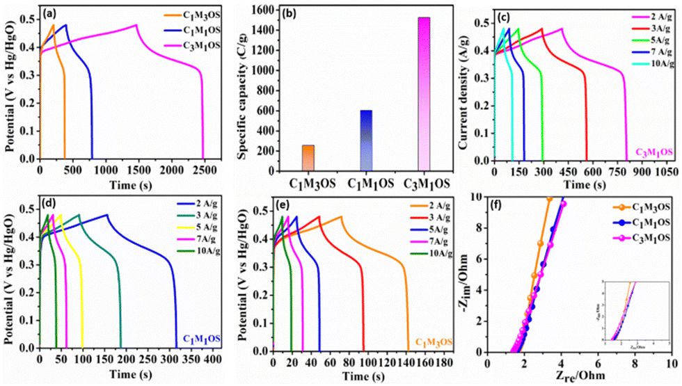 | ||
| Fig. 5 Three-electrode electrochemical measurements: (a) and (b) GCD profiles and the corresponding specific capacity of the C1M3OS, C1M1OS, and C3M1OS electrodes at a current density of 1 A g−1. GCD profiles at various current densities (2–10 A g−1) of (c) C3M1OS, (d) C1M1OS, and (e) C1M3OS. (f) Nyquist plots for the designed C1M3OS, C1M1OS, and C3M1OS electrodes. | ||
| Electrode material | Current density | Electrolyte | C sp (F g−1) | Ref. |
|---|---|---|---|---|
| (CuS/MnS)@NF | 1 | 2 M KOH | 1517.07 | 25 |
| CoMn2O4 | 1 | 3 M KOH | 808 | 83 |
| Cu7S4@LSC | 1 | 1 M KOH | 1431.1 | 84 |
| MnCo2S4 | 1 | 2 M KOH | 1402 | 85 |
| NiCo2S4 | 5 | 2 M KOH | 666.27 | 86 |
| MnO2/Co-NiLDH | 1 | 1 M KOH | 1436 | 87 |
| CuO/Cu2O/Cu | 1.67 | 6 M KOH | 878 | 88 |
| NiAl-LDH/MnO2 | 1 | 6 M KOH | 1092 | 89 |
| Cu7S4/NiS | 1 | 3 M KOH | 1205 | 90 |
| Double-shell CuS | 1 | 2 M KOH | 843 | 26 |
| CoMn2O4@MnS | 1 | 3 M KOH | 213.0 mA h g−1 | 82 |
| C1M3OS | 1 | 2 M KOH | 533.9 | This work |
| C1M1OS | 1 | 2 M KOH | 1258.1 | This work |
| C3M1OS | 1 | 2 M KOH | 3177.2 | This work |
To investigate the feasibility of using the C3M1OS electrode in real-life applications, an asymmetric device was constructed using commercial activated carbon (AC) as the negative pole, C3M1OS (the best performing electrode) as the positive pole, and filter paper as a separator placed between the two poles. The device is fabricated with a weight of approximately 4 mg, i.e. commercial mass loading. Fig. 6(a) demonstrates the recorded CV of the C3M1OS//AC device in 2 M KOH over a wide cell voltage regime (1.9–2 V) to identify the stable potential window. The supercapacitor device can withstand 2 V, as there is no observed leap in current at this voltage, indicating that this potential window is safe for the C3M1OS//AC device to operate without electrolyte decomposition. Fig. 6(b) depicts the CV profiles of the C3M1OS//AC device at several sweep rates starting from 5 to 100 mV s−1 across a wide potential window of up to 2 V. The asymmetric device incorporates the combined features of an EDL capacitor, originating from the AC electrode, and faradaic behavior contribution ascribed to the C3M1OS electrode, in agreement with the results of the Trasatti method, proving the mixed charge storage mechanism of the assembled device.
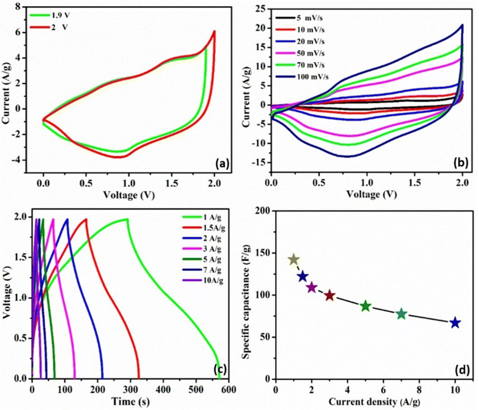 | ||
| Fig. 6 Electrochemical characteristics of the C3M1OS//AC asymmetric device: (a) CV profiles at various potential windows, (b) CVs at different scan rates ranging from 5 to 100 mV s−1, (c) GCDs at several current densities ranging from 1 to 10 A g−1, and (d) specific capacitance recorded at different current densities. | ||
Furthermore, the device retains the same CV shape even at a high scan rate, illustrating the excellent reversibility of the fabricated device over a large and suitable operating cell voltage. In addition, the chronopotentiometric charge/discharge profiles are probed at different current densities from 1 to 10 A g−1 within a potential window of 1.97 V, Fig. 6(c). The device's GCD profiles manifested a triangular shape with non-linearity, consistent with the CV results. Note that symmetrical charging and discharging curves are noticed even at high current density, confirming the superior electrochemical reversibility of the device with superb Coulombic efficiency. The device exhibits an exceptional specific capacitance of 142 F g−1 at 1 A g−1. Upon increasing the current density to 10 A g−1, the device acquires a specific capacitance of 67 F g−1 with an outstanding rate capability of 47%. Accordingly, our asymmetric device (C3M1OS//AC) can operate over a wide working voltage range with superb specific capacitance to meet the demand for high-power supercapacitors to be convenient for practical application.
Long term cycling stability is one of the significant performance parameters of supercapacitor devices, which is tested by performing a series of GCD cycles for the C3M1OS//AC device at 10 A g−1. Over 10000 cycles, the C3M1OS//AC device sustains 91% of its initial specific capacitance with an efficiency of ∼100%, indicating the outstanding cyclic stability of the assembled device, Fig. 7(a). The SEM image of the electrode after cycling (Fig. S7a, ESI†) revealed no morphological change of the nanocube-like structure covered with nanoneedles with the presence of some aggregates. Additionally, the EDX and XPS analyses shown in Fig. S7b and c (ESI†) confirmed the presence of all chemical elements (Cu, Mn, S, and O) after cycling, demonstrating the stability of the C3M1OS electrode. Furthermore, the energy and power densities are the other two critical characteristics of supercapacitors, which can be calculated based on the charge/discharge curves according to eqn (4) and (5). Based on the Ragone plot at different current densities (Fig. 7(b)), the C3M1OS//AC device can acquire a very high energy density of 76.56 W h kg−1 along with a power density of 985.01 W kg−1 at 1 A g−1. In addition, the asymmetric device showed a maximum power density of 9850.09 W kg−1 with an energy density of 36.12 W h kg−1 at 10 A g−1. Note that the fabricated C3M1OS//AC device outperforms those reported in the literature of relevant materials in terms of electrochemical performance (energy and power density), such as RGO–Mn–Ni–Co–OX//RGO (35.6 W kg−1 at 0.69 kW h kg−1),73 Ni–Co–Mn oxide//AC (36.4 W kg−1 at 0.32 kW h kg−1),93 AC//Mn–Co–Fe (11.4 W kg−1 at 1125 W h kg−1),94 NiCoMn–OH//AC (43.2 W kg−1 at 790 W h kg−1),95 NiCoMn–S//AC (50 W kg−1 at 850 W h kg−1),96 Ni(OH)2–MnO2@C//AC (39.1 W kg−1 at 221.4 W h kg−1),97 CuO//AC (19.7 W h kg−1 at 700 W kg−1),98 Cu–Ni3S2//AC (33.7 W h g−1 at 850.1 W kg−1),99 and MNC OS/NF//AC/CC (31.5 W h kg−1 at 2616.3 W kg−1).100 On the other hand, to elucidate the electrochemical properties and evaluate the electrochemical resistance of the assembled device, EIS measurements were conducted. Fig. S8 (ESI†) depicts the Nyquist plot of the C3M1OS//AC device after prolonged cycling (10000 cycles) over the frequency range between 10 MHz and 1000 kHz under open circuit conditions, to estimate the charge transfer and Ohmic resistances.101,102 Accordingly, the asymmetric device exhibited a small ESR and RCT of 2.8 and 1.5 Ω, respectively, indicating good electrochemical conductivity and fast transportation of charges. The excellent electrochemical activity of the C3M1OS//AC device with a large operating potential window can be related to the synergistic effects of constituents (Cu and Mn), the binder-free nature of the electrode, the presence of O with S that enhances the electrode's conductivity, and flexibility in the shape of the formed nanostructures.8,99,103–106
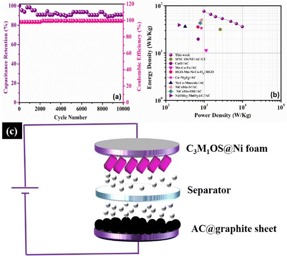 | ||
| Fig. 7 Electrochemical characteristics of the C3M1OS//AC asymmetric device: (a) recyclability test at 10 A g−1 and the corresponding Coulombic efficiency, (b) Ragone plot at several current loads in comparison with previously reported devices in the literature, and (c) schematic diagram of the developed C3M1OS//AC asymmetric device. | ||
To unveil the reason behind the outstanding performance of the C3M1OS material, DFT calculations were performed to elucidate the electronic features of the C1M3OS, C1M1OS and C3M1OS electrodes. The three systems’ geometry was optimized, as shown in Fig. 8. The oxysulfide family (CMOS) adopts the tetragonal layered arrangement with a P4/nmm space group during crystallization. Fig. 8 shows that the crystal structure of C1M1OS consists of alternately stacked manganese oxide layers with ionic bonds and copper sulfide layers having covalent bonds over the z-axis. This was confirmed by Bader charge analysis. From the Bader net charge, it was observed that oxygen withdrew electrons from manganese more than copper, and it showed charge transfer from metals (Mn and Cu) to oxygen and sulphur, as displayed in Table S1 (ESI†).
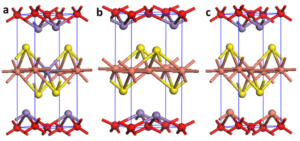 | ||
| Fig. 8 Crystal structure of (a) C1M3OS, (b) C1M1OS, and (c) C3M1OS, where orange, purple, yellow, and red are Cu, Mn, S, and O atoms, respectively. | ||
The band gap (Eg) and the projected density of states (PDOS) were calculated, as shown in Fig. 9, using separated hybrid functional HSE06, as it is known for its accuracy in calculating the electronic properties.107 It was noted that the band gap is decreased by increasing the copper content to 2.01, 1.59, and 1.34 eV for C1M3OS, C1M1OS, and C3M1OS, respectively. This indicates higher conductivity for C3M1OS than the others. The band gap of C1M1OS was determined experimentally in the literature and was found to be 1.5–1.6 eV,103 confirming high accuracy of our results. The decrease in the band gap with increasing Cu arises from the conduction band minima (CBM)-Cu 3d orbitals. Substituting Cu with Mn could change the conduction band position. The metal sulfide layers initially specify the band gap of CMOS compounds and are less contingent on the metal oxide layers.108 From DOS, the metal 4s orbitals fundamentally dominate the CBM. However, admixed metal 3d and p orbitals at most monitor the valence band maximum (VBM). This means that the electronic structure of the CBM is diverse in the three systems, as the CBM fundamentally consists of metal 4s orbitals with little sharing from the metal d orbitals.
 | ||
| Fig. 9 Electronic band structure and projected DOS of C1M3OS, C1M1OS, and C3M1OS. The Fermi level is defined as the top of the valence band represented by the dashed line at 0 eV. | ||
Conclusions
A facile yet optimized wet chemistry strategy was demonstrated for the successful fabrication of Cu–Mn binary oxysulfides with different Cu:Mn ratios directly on a Ni foam substrate. The optimal Cu:Mn ratio along with the presence of both O and S ions enhanced the electrode conductivity, flexibility in the shape of the nanostructures formed, and the electrochemical performance. The most effective electrode (C3M1OS) exhibited the ability to deliver an outstanding specific capacitance of 3177.2 F g−1 (1525 C g−1) at a current density of 1 A g−1. The C3M1OS electrode displayed the smallest Ohmic resistance of 1.35 Ω with an RCT of 1.04 Ω. The faradaic process was the dominant storage mechanism, where ∼93% of the total capacity originated from diffusion-controlled processes (Cf) and only 7% originated from surface-confined processes (Cdl). Impressively, the assembled C3M1OS//AC device withstands a large operating potential window of 1.97 V and manifests a remarkable cyclic stability of 91% over 10000 charge/discharge cycles at 10 A g−1. The C3M1OS//AC device acquired a very high energy density of 76.56 W h kg−1 along with a power density of 985.01 W kg−1 at 1 A g−1. The DFT calculations confirmed the experimental results and revealed a low band gap and high conductivity of C3M1OS. It was noted that the band gap is decreased by increasing the copper content. We hope that this study encourages the development of advanced metal oxysulfides with facile preparation methods and their use in high-performance energy conversion/storage devices.
Conflicts of interest
There are no conflicts to declare.References
- A. M. Mohamed, D. M. Sayed and N. K. Allam, ACS Appl. Mater. Interfaces, 2023, 15, 16755–16767 CrossRef CAS PubMed.
- S. A. Teama, H. M. El Sharkawy and N. K. Allam, Energy Fuels, 2023, 37, 7468–7478 CrossRef CAS.
- S. Liu, D. Ni, H.-F. Li, K. N. Hui, C.-Y. Ouyang and S. C. Jun, J. Mater. Chem. A, 2018, 6, 10674–10685 RSC.
- L. Ghanem, M. Taha, B. Shaheen and N. K. Allam, ACS Appl. Mater. Interfaces, 2023 DOI:10.1021/acsami.3c11494.
- P. Asen and A. Esfandiar, Electrochim. Acta, 2021, 391, 138948 CrossRef CAS.
- S. Liu, L. Kang, J. Zhang, S. C. Jun and Y. Yamauchi, NPG Asia Mater., 2023, 15, 9 CrossRef CAS.
- S. Liu, L. Kang, J. Zhang, E. Jung, S. Lee and S. C. Jun, Energy Storage Mater., 2020, 32, 167–177 CrossRef.
- L. Liu, Nanoscale, 2013, 5, 11615–11619 RSC.
- M. Liu, Y. Fu, H. Ma, T. Wang, C. Guan and K. Hu, Electrochim. Acta, 2016, 191, 916–922 CrossRef CAS.
- B. Wei, L. Meng, H. Li, C. Yao and Q. Han, J. Alloys Compd., 2017, 721, 285–290 CrossRef CAS.
- Y. Kuai, M. Liu, T. Wang, Y. Fu, H. Ma, Q. Jiang, C. Guan and K. Hu, Ionics, 2017, 23, 1391–1398 CrossRef CAS.
- M. R. Pallavolu, H. R. Goli, Y. A. Kumar, M. Naushad, S. Sambasivam and A. Sreedhar, J. Alloys Compd., 2022, 926, 166814 CrossRef CAS.
- D. M. Sayed and N. Bahnasawy, Adv. Mater. Interface, 2023, 2300111 CrossRef.
- P. Asen, S. Shahrokhian and A. I. Zad, J. Electroanal. Chem., 2018, 818, 157–167 CrossRef CAS.
- S. Liu, L. Kang, J. Hu, E. Jung, J. Zhang, S. C. Jun and Y. Yamauchi, ACS Energy Lett., 2021, 6, 3011–3019 CrossRef CAS.
- M. Ashourdan, A. Semnani, F. Hasanpour and S. E. Moosavifard, J. Energy Storage, 2021, 36, 102449 CrossRef.
- C. Zhang, A. Xie, W. Zhang, J. Chang, C. Liu, L. Gu, X. Duo, F. Pan and S. Luo, J. Energy Storage, 2021, 34, 102181 CrossRef.
- S. C. Sekhar, G. Nagaraju, B. Ramulu and J. S. Yu, ACS Appl. Mater. Interfaces, 2018, 10, 36976–36987 CrossRef CAS PubMed.
- G. Harichandran, S. Radha, P. Divya and J. Yesuraj, J. Mater. Sci.: Mater. Electron., 2020, 31, 1646–1653 CrossRef CAS.
- T. Lama Tamang, S. G. Mohamed, G. Dhakal and J. J. Shim, J. Colloid Interface Sci., 2022, 624, 494–504 CrossRef CAS PubMed.
- H. M. El Sharkawy, A. S. Dhmees, A. R. Tamman, S. M. El Sabagh, R. M. Aboushahba and N. K. Allam, J. Energy Storage, 2020, 27, 101078 CrossRef.
- J. Zhao, Z. Ma, C. Qiao, Y. Fan, X. Qin and G. Shao, ACS Appl. Mater. Interfaces, 2022, 14, 34686–34696 CrossRef CAS PubMed.
- W. Lu, B.-B. Xie, C. Yang, C. Tian, L. Yan, J. Ning, S. Li, Y. Zhong and Y. Hu, Small, 2023, 2302629 CrossRef PubMed.
- H. He, X. Yang, L. Wang, X. Zhang, X. Li and W. Lü, CrystEngComm, 2020, 22, 6047–6056 RSC.
- M. Zhai, Y. Cheng, Y. Jin and J. Hu, Int. J. Hydrogen Energy, 2019, 44, 13456–13465 CrossRef CAS.
- J. Guo, X. Zhang, Y. Sun, X. Zhang, L. Tang and X. Zhang, J. Power Sources, 2017, 355, 31–35 CrossRef CAS.
- I. M. Badawy, G. E. Khedr, A. M. Hafez, E. A. Ashour and N. Allam, Chem. Commun., 2023, 59, 7974–7977 RSC.
- A. A. M. Ismail, L. G. Ghanem, A. A. Akar, G. E. Khedr, M. Ramadan, B. S. Shaheen and N. K. Allam, J. Mater. Chem. A, 2023, 11, 16009–16018 RSC.
- S. M. Fawzy, G. E. Khedr and N. K. Allam, Int. J. Hydrogen Energy, 2023, 48, 33111–33118 CrossRef CAS.
- A. M. Mohamed, W. A. Abbas, G. E. Khedr and W. Abass, Sci. Rep., 2022, 12, 15989 CrossRef CAS PubMed.
- A. M. Agour, E. Elkersh, G. E. Khedr, H. G. El-Aqapa and N. K. Allam, ACS Appl. Nano Mater., 2023, 6, 15980–15989 CrossRef CAS.
- H. G. El-Aqapa, I. M. Badawy, G. E. Khedr, A. M. Agour, D. M. Sayed, M. M. Taha and N. K. Allam, Catal. Sci. Technol., 2023, 13, 5175–5179 RSC.
- H. M. El Sharkawy, D. M. Sayed, A. S. Dhmees, R. M. Aboushahba and N. K. Allam, ACS Appl. Energy Mater., 2020, 3, 9305–9314 CrossRef CAS.
- Y. I. Mesbah, N. Ahmed, M. M. Hasan and N. K. Allam, Mater. Today Chem., 2023, 30, 101521 CrossRef CAS.
- A. Ali, M. Ammar, A. Mukhtar, T. Ahmed, M. Ali, M. Waqas, M. N. Amin and A. Rasheed, J. Electroanal. Chem., 2020, 857, 113710 CrossRef CAS.
- H. C. Chen, S. Jiang, B. Xu, C. Huang, Y. Hu, Y. Qin, M. He and H. Cao, J. Mater. Chem. A, 2019, 7, 6241–6249 RSC.
- H. M. El Sharkawy, A. M. Mohamed, M. Ramadan and N. K. Allam, J. Energy Storage, 2022, 54, 105272 CrossRef.
- B. Huang, H. Wang, S. Liang, H. Qin, Y. Li, Z. Luo, C. Zhao, L. Xie and L. Chen, Energy Storage Mater., 2020, 32, 105–114 CrossRef.
- A. M. Elbanna, K. E. Salem, A. M. Mokhtar, M. Ramadan, M. Elgamal, H. A. Motaweh, H. M. Tourk, M. A. Gepreel and N. K. Allam, J. Phys. Chem. C, 2021, 125, 12504–12517 CrossRef CAS.
- L. Feng, Z. Xuan, H. Zhao, Y. Bai, J. Guo, C. Wei Su and X. Chen, Nanoscale Res. Lett., 2014, 9, 1–8 CrossRef CAS PubMed.
- Y. Zhou, X. Liu, K. Wang, J. Li, X. Zhang, X. Jin, X. Tang, X. Zhu, R. Zhang, X. Jiang and B. Liu, Results Phys., 2019, 12, 1893–1900 CrossRef.
- Y. Wang, C. Hou, X. Lin, H. Jiang, C. Zhang and G. Liu, Appl. Phys. A: Mater. Sci. Process., 2021, 127, 1–7 CrossRef.
- D. Zhu, L. Wang, W. Yu and H. Xie, Sci. Rep., 2018, 8, 1–12 CAS.
- M. Samadi Kazemi and A. Sobhani, Arabian J. Chem., 2023, 16, 104754 CrossRef CAS.
- S. S. Kalanur and H. Seo, RSC Adv., 2017, 7, 11118–11122 RSC.
- D. Xu, R. Jiao, Y. Sun, D. Sun, X. Zhang, S. Zeng and Y. Di, Nanoscale Res. Lett., 2016, 11, 1–10 CrossRef CAS PubMed.
- W. Lu, J. Shen, P. Zhang, Y. Zhong, Y. Hu and X. W. (David) Lou, Angew. Chem., Int. Ed., 2019, 58, 15441–15447 CrossRef CAS PubMed.
- W. Lu, Z. Yuan, C. Xu, J. Ning, Y. Zhong, Z. Zhang and Y. Hu, J. Mater. Chem. A, 2019, 7, 5333–5343 RSC.
- Q. Li, W. Lu, Z. Li, J. Ning, Y. Zhong and Y. Hu, Chem. Eng. J., 2020, 380, 122544 CrossRef CAS.
- J. Hyeon Jo, S.-T. Myung, R. Anggraini, S. Saidah Siregar, A. Awaluddin al, G.-Q. Han, Y.-R. Liu, W.-H. Hu, H. Wang, Z. Lu, D. Qian, Y. Li and W. Zhang, Nanotechnology, 2007, 18, 115616 CrossRef.
- M. Zheng, H. Zhang, X. Gong, R. Xu, Y. Xiao, H. Dong, X. Liu and Y. Liu, Nanoscale Res. Lett., 2013, 8, 1–7 CrossRef PubMed.
- M. Kumar Trivedi, Am. J. Phys. Appl., 2015, 3, 215–220 Search PubMed.
- P. K. Raul, S. Senapati, A. K. Sahoo, I. M. Umlong, R. R. Devi, A. J. Thakur and V. Veer, RSC Adv., 2014, 4, 40580–40587 RSC.
- Y. Wang, F. Jiang, J. Chen, X. Sun, T. Xian and H. Yang, Nanomaterials, 2010, 10, 178 CrossRef PubMed.
- J. C. Parlebas, Phys. Status Solidi, 1993, 178, 9–35 CrossRef CAS.
- S. Nandanwar, S. Borkar, J. H. Cho and H. J. Kim, Catalysis, 2020, 11, 36 Search PubMed.
- D. He, G. Wang, G. Liu, J. Bai, H. Suo and C. Zhao, J. Alloys Compd., 2017, 699, 706–712 CrossRef CAS.
- Z. Huang, W. Zhou, C. Ouyang, J. Wu, F. Zhang, J. Huang, Y. Gao and J. Chu, Sci. Rep., 2015, 5, 1–8 Search PubMed.
- M. M. Alam, M. M. Rahman, M. T. Uddin, A. M. Asiri, J. Uddin and M. A. Islam, Curr. Res. Biotechnol., 2020, 2, 176–186 CrossRef.
- M. Wang, K. Chen, J. Liu, Q. He, G. Li and F. Li, Catalysis, 2018, 8, 138 Search PubMed.
- A. M. Elbanna, K. E. Salem, M. Ramadan and N. K. Allam, Energy Fuels, 2023, 37, 3942–3956 CrossRef CAS.
- I. Hussain, C. Lamiel, S. G. Mohamed, S. Vijayakumar, A. Ali and J. J. Shim, J. Ind. Eng. Chem., 2019, 71, 250–259 CrossRef CAS.
- N. Ahmed, B. A. Ali, M. Ramadan and N. K. Allam, ACS Appl. Energy Mater., 2019, 2, 3717–3725 CrossRef CAS.
- H. Wang, Y. Yang, Q. Li, W. Lu, J. Ning, Y. Zhong, Z. Zhang and Y. Hu, Sci. China Mater., 2021, 64, 840–851 CrossRef CAS.
- W. Lu, Y. Yang, T. Zhang, L. Ma, X. Luo, C. Huang, J. Ning, Y. Zhong and Y. Hu, J. Colloid Interface Sci., 2021, 590, 226–237 CrossRef CAS PubMed.
- L. G. Ghanem, M. M. Taha, M. Salama and N. K. Allam, Sustainable Energy Fuels, 2022, 6, 4787–4799 RSC.
- A. A. Saleh, A. Amer, D. M. Sayed and N. K. Allam, Electrochim. Acta, 2021, 380, 138197 CrossRef CAS.
- J. Raghav, T. Agarkar, A. Kumar and S. Roy, Mater. Chem. Phys., 2023, 296, 127360 CrossRef CAS.
- L. Zhang, T. J. Huang and H. Gong, Phys. Chem. Chem. Phys., 2017, 19, 10462–10469 RSC.
- H. A. Ghaly, A. G. El-Deen, E. R. Souaya and N. K. Allam, Electrochim. Acta, 2019, 310, 58–69 CrossRef CAS.
- N. Ahmed, B. A. Ali and N. K. Allam, Electrochim. Acta, 2021, 396, 139191 CrossRef CAS.
- P. Xu, K. Ye, D. Cao, J. Huang, T. Liu, K. Cheng, J. Yin and G. Wang, J. Power Sources, 2014, 268, 204–211 CrossRef CAS.
- A. E. Elkholy, F. El-Taib Heakal and N. K. Allam, Electrochim. Acta, 2019, 296, 59–68 CrossRef CAS.
- A. M. Mohamed, A. O. Abo El Naga, T. Zaki, H. B. Hassan and N. K. Allam, ACS Appl. Energy Mater., 2020, 3, 8064–8074 CrossRef CAS.
- D. M. Sayed, M. M. Taha, L. G. Ghanem, M. S. El-Deab and N. K. Allam, J. Power Sources, 2020, 480, 229152 CrossRef CAS.
- H. M. El Sharkawy, S. A. Teama and N. K. Allam, ACS Appl. Eng. Mater., 2022, 1, 556–567 CrossRef.
- S. Ardizzone, G. Fregonara and S. Trasatti, Electrochim. Acta, 1990, 35, 263–267 CrossRef CAS.
- H. M. El Sharkawy, A. A. Saleh, A. M. Elbanna and N. K. Allam, ACS Appl. Nano Mater., 2023, 6, 4875–4886 CrossRef CAS.
- K. Yu, W. M. Tang and J. Dai, Phys. Status Solidi, 2018, 215, 1800147 Search PubMed.
- P. Kulkarni, S. K. Nataraj, R. G. Balakrishna, D. H. Nagaraju and M. V. Reddy, J. Mater. Chem. A, 2017, 5, 22040–22094 RSC.
- W. Hu, R. Chen, W. Xie, L. Zou, N. Qin and D. Bao, ACS Appl. Mater. Interfaces, 2014, 6, 19318–19326 CrossRef CAS PubMed.
- S. Sambasivam, C. V. V. M. Gopi, H. M. Arbi, Y. A. Kumar, H. J. Kim, S. Al Zahmi and I. M. Obaidat, J. Energy Storage, 2021, 36, 102377 CrossRef.
- X. Chen, X. Liu, Y. Liu, Y. Zhu, G. Zhuang, W. Zheng, Z. Cai and P. Yang, RSC Adv., 2018, 8, 31594–31602 RSC.
- M. Zhang, H. Hu, J. Qi, F. Wei, Q. Meng, Y. Ren, Z. Zhan, Y. Sui and Z. Sun, Electrochim. Acta, 2021, 366, 137362 CrossRef CAS.
- A. M. Elshahawy, X. Li, H. Zhang, Y. Hu, K. H. Ho, C. Guan and J. Wang, J. Mater. Chem. A, 2017, 5, 7494–7506 RSC.
- H. Nan, M. Liu, Q. Zhang, M. Wang, S. Liu, L. Qiao, X. Hu and H. Tian, J. Power Sources, 2020, 451, 227822 CrossRef CAS.
- H. Luo, B. Wang, T. Liu, F. Jin, R. Liu, C. Xu, C. Wang, K. Ji, Y. Zhou, D. Wang and S. Dou, Energy Storage Mater., 2019, 19, 370–378 CrossRef.
- P. Xu, J. Liu, T. Liu, K. Ye, K. Cheng, J. Yin, D. Cao, G. Wang and Q. Li, RSC Adv., 2016, 6, 28270–28278 RSC.
- W. Zheng, S. Sun, Y. Xu, R. Yu and H. Li, J. Alloys Compd., 2018, 768, 240–248 CrossRef CAS.
- H. Cao, X. Wang, X. Chen, H. Liu, J. Zheng and W. Zhou, J. Mater. Chem. A, 2017, 5, 20729–20736 RSC.
- Z. H. Huang, F. F. Sun, M. Batmunkh, W. H. Li, H. Li, Y. Sun, Q. Zhao, X. Liu and T. Y. Ma, J. Mater. Chem. A, 2019, 7, 11826–11835 RSC.
- I. M. Badawy, A. M. Elbanna, M. Ramadan and N. K. Allam, Electrochim. Acta, 2022, 408, 139932 CrossRef CAS.
- C. Wu, J. Cai, Y. Zhu and K. Zhang, ACS Appl. Mater. Interfaces, 2017, 9, 19114–19123 CrossRef CAS PubMed.
- Y. Du, G. Li, M. Chen, X. Yang, L. Ye, X. Liu and L. Zhao, Chem. Eng. J., 2019, 378, 122210 CrossRef CAS.
- D. Guo, X. Song, L. Tan, H. Ma, H. Pang, X. Wang and L. Zhang, ACS Appl. Mater. Interfaces, 2018, 10, 42621–42629 CrossRef CAS PubMed.
- J. Li, W. Cao, N. Zhou, F. Xu, N. Chen, Y. Liu and G. Du, Electrochim. Acta, 2020, 343, 136139 CrossRef CAS.
- S. E. Moosavifard, M. F. El-Kady, M. S. Rahmanifar, R. B. Kaner and M. F. Mousavi, ACS Appl. Mater. Interfaces, 2015, 7, 4851–4860 CrossRef CAS PubMed.
- G. Li, X. Cui, B. Song, H. Ouyang, K. Wang, Y. Sun and Y. Wang, Chem. Eng. J., 2020, 388, 124319 CrossRef CAS.
- H. Rao Goli, M. V. Basaveswara Rao, N. Purushotham Reddy, M. Reddy Pallavolu, P. Wu, Y. K. Han, G. Seeta Rama Raju and P. A. Alvi, Chem. Eng. J., 2022, 446, 137347 CrossRef CAS.
- S. Chen, G. Yang and H. Zheng, Electrochim. Acta, 2016, 220, 296–303 CrossRef CAS.
- M. Samir, N. Ahmed, M. Ramadan and N. K. Allam, ACS Sustainable Chem. Eng., 2019, 7, 13471–13480 CrossRef CAS.
- N. M. Deyab, N. Ahmed and N. K. Allam, ChemNanoMat, 2020, 6, 1513–1518 CrossRef CAS.
- X. Chen, H. Abdullah and D. H. Kuo, Sci. Rep., 2017, 7, 1–12 CrossRef.
- L. Sharma, A. Mathur and A. Halder, Sustainable Energy Fuels, 2021, 5, 3836–3846 RSC.
- J. Liu, C. Guan, C. Zhou, Z. Fan, Q. Ke, G. Zhang, C. Liu and J. Wang, Adv. Mater., 2016, 28, 8732–8739 CrossRef CAS PubMed.
- S. Jiang, Y. Qiao, T. Fu, W. Peng, T. Yu, B. Yang, R. Xia and M. Gao, ACS Appl. Mater. Interfaces, 2021, 13, 34374–34384 CrossRef CAS PubMed.
- T. Le Bahers, S. Haller, T. Le Mercier and P. Barboux, J. Phys. Chem. C, 2015, 119, 17585–17595 CrossRef CAS.
- H. Hiramatsu, H. Yanagi, T. Kamiya and K. Ueda, Chem. Mater., 2008, 326–334 CrossRef CAS.
Footnotes |
| † Electronic supplementary information (ESI) available. See DOI: https://doi.org/10.1039/d3ya00415e |
| ‡ These authors contributed equally to this work. |
| This journal is © The Royal Society of Chemistry 2023 |