
 Open Access Article
 This Open Access Article is licensed under a
 Creative Commons Attribution 3.0 Unported Licence
Stochastic microstructure modeling of SOC electrodes based on a pluri-Gaussian method†
Philip
Marmet
 *ac,
Lorenz
Holzer
a,
Thomas
Hocker
a,
Vinzenz
Muser
a,
Gernot K.
Boiger
a,
Mathias
Fingerle
b,
Sarah
Reeb
b,
Dominik
Michel
b and
Joseph M.
Brader
c
*ac,
Lorenz
Holzer
a,
Thomas
Hocker
a,
Vinzenz
Muser
a,
Gernot K.
Boiger
a,
Mathias
Fingerle
b,
Sarah
Reeb
b,
Dominik
Michel
b and
Joseph M.
Brader
c
aZurich University of Applied Sciences, Institute of Computational Physics, CH-8400 Winterthur, Switzerland. E-mail: mame@zhaw.ch
bMath2Market GmbH, D-67657 Kaiserslautern, Germany
cDepartment of Physics, University of Fribourg, CH-1700 Fribourg, Switzerland
First published on 9th October 2023
Abstract
Digital Materials Design (DMD) offers new possibilities for data-driven microstructure optimization of solid oxide cells (SOC). Despite the progress in 3D-imaging, experimental microstructure investigations are typically limited to only a few tomography analyses. In this publication, a DMD workflow is presented for extensive virtual microstructure variation, which is based on a limited number of real tomography analyses. Real 3D microstructures, which are captured with FIB-tomography from LSTN–CGO anodes, are used as a basis for stochastic modeling. Thereby, digital twins are constructed for each of the three real microstructures. The virtual structure generation is based on the pluri-Gaussian method (PGM). In order to match the properties of selected virtual microstructures (i.e., digital twins) with real structures, the construction parameters for the PGM-model are determined by interpolation of a database of virtual structures. Moreover, the relative conductivities of the phases are optimized with morphological operations. The digital twins are then used as anchor points for virtual microstructure variation of LSTN–CGO anodes, covering a wide range of compositions and porosities. All relevant microstructure properties are determined using our standardized and automated microstructure characterization procedure, which was recently published. The microstructure properties can then e.g., be used as input for a multiphysics electrode model to predict the corresponding anode performances. This set of microstructure properties with corresponding performances is then the basis to provide design guidelines for improved electrodes. The PGM-based structure generation is available as a new Python app for the GeoDict software package.
1 Introduction
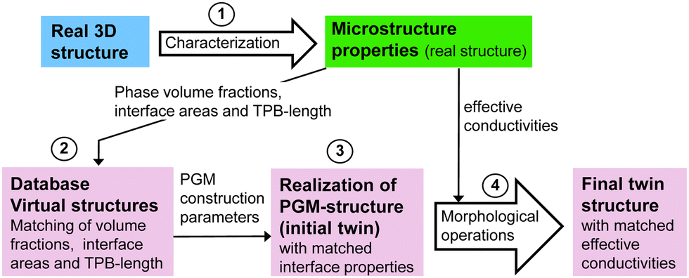
Solid oxide cell (SOC) technology is a promising solution for the efficient energy conversion. In the solid oxide fuel cell (SOFC) mode, renewable fuels or natural gas are used for decentral heat and power generation. Alternatively, in the solid oxide electrolysis cell (SOEC) mode, this technology provides an important option for conversion and storage of renewable energy (power-to-gas). However, there are still issues especially concerning the degradation behaviour and life-time, which calls for the development of alternative material systems. For example, the most commonly used anode material in SOFCs is Nickel – yttria-stabilized zirconia (Ni-YSZ), which shows various types of degradation1,2 including Ni coarsening,3 carbon coking,4–6 sulphur poisoning7 and mechanical damage caused by redox cycling.8 Moreover, the electrochemical reaction is bound to the three-phase boundaries (TPB), which induces a specific microstructure limitation towards the electrochemical activity in Ni-YSZ cermet anodes. As an alternative anode concept, mixed ionic and electronic conductive (MIEC) materials are drawing much attention. An obvious advantage of MIEC materials is the fact that the fuel oxidation reaction can take place on the complete MIEC/pore interface (two-phase boundaries). Thereby, composite ceramic anodes consisting of perovskite and gadolinium doped ceria (CGO) represent one of the most important alternative material concepts (e.g., ref. 1, 9, 10 and 11). Thereby, the Ni-phase is replaced by a conductive perovskite-phase (e.g., La, Sr, titanate) with the goal to get rid of the harmful degradation phenomena associated with Ni. In addition, CGO is a MIEC phase with relatively high ionic conductivity and catalytic activity. The optimization of such ceramic electrodes is currently the topic of ongoing research.To accelerate the research in this field in a cost-efficient way, we suggest supporting the development using Digital Materials Design (DMD) methodologies. In Fig. 1, a DMD workflow for SOC electrodes is illustrated. The overall goal of this workflow is to establish a quantitative relationship between fabrication parameters, microstructure properties and cell performance, in order to accelerate the microstructure optimization in a systematic and knowledge-based way with digital feedback loops. In our DMD approach we combine stochastic microstructure modeling (Fig. 1, red frame), virtual testing of 3D microstructures and a multiscale-multiphysics electrode model to explore the design space by performing parametric studies. The basis for the DMD process is a set of fabricated solid oxide cells. The real microstructures are reconstructed using FIB-SEM tomography for a small number of fabricated cells representing a variation of the parameters to be optimized (e.g., composition and porosity). Digital microstructure twins with matching microstructure properties are then constructed for each real structure using a pluri-Gaussian method, which is the main focus of the present paper. On that basis, the microstructure can be virtually varied for a large parameter space in a realistic way. The real and subsequently the virtual 3D structures need to be characterized quantitatively by means of image analysis and numerical simulations. A standardized and automated microstructure characterization tool has been developed (see Marmet et al.13), which enables the fast determination of an extensive set of microstructure properties relevant for SOC electrodes. The determined microstructure properties for the virtual structure variation can be used directly for microstructure optimization (based on qualitative estimations) or alternatively, the microstructure properties can serve as an input for multiphysics electrode models as illustrated in Fig. 1. The multiphysics simulation model can be used to predict the impact of the microstructure variation on the electrode performance. This model-based performance prediction enables to establish the relationship between fabrication parameters, materials choices, microstructure properties and cell-performance. Due to the integration of stochastic modeling (pluri-Gaussian method) and its combination with automated characterization and model-based performance prediction, the number of the involved 3D microstructures can be significantly increased. This approach is thus capable to explore a much larger design space than it would be possible with experimental methods only. On this basis, design guidelines for the fabrication of improved electrode performance can be provided, which closes the loop of this iterative workflow. This DMD workflow is described in more detail in the ESI,† of a previous publication (Marmet et al.13), which is dealing with standardized and automated microstructure characterization. In the present publication, we will describe the construction of digital microstructure twins based on a pluri-Gaussian method and the virtual microstructure variation on that basis (Fig. 1, red frame), which is another key element in our DMD approach.
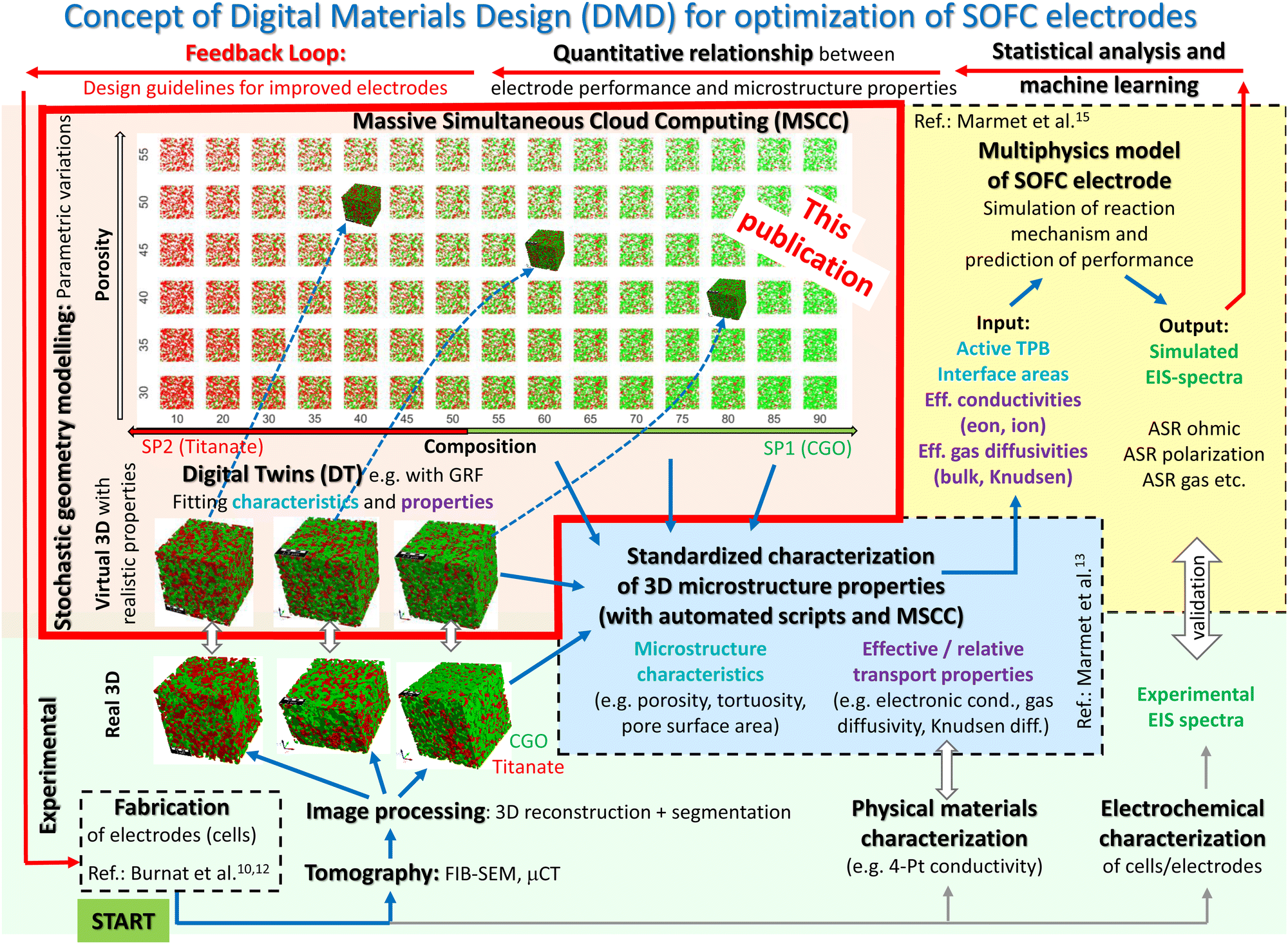 | ||
| Fig. 1 Overview of the entire workflow for Digital Materials Design (DMD), which includes various methodological modules. The module of stochastic geometry modeling and associated realization of digital twins, which is the main topic of the present paper, is highlighted with a red frame. The other methodological modules of the DMD workflow are described in great detail in separate papers, such as the module including materials processing and cell fabrication (see Burnat et al.10,12), the modules for imaging and standardized microstructure characterization (Marmet et al.13 and Holzer et al.14), and the module for performance prediction with a multiphysics electrode model (Marmet et al.15). A detailed description of the entire DMD workflow, including all the different modules, is also given in the PhD thesis of Ph. Marmet.16 | ||
A suitable method for virtual 3D structure generation is the basis for stochastic modeling. An overview of microstructure modeling approaches for electrochemical devices like batteries, PEM fuel cells and SOFCs can be found in Ryan and Mukherjee.17 Thereby, different stochastic 3D reconstruction methods are presented, which include Monte Carlo modeling, dynamic particle packing, stochastic grids, simulated annealing and controlled random generation. A general overview for stochastic microstructure modeling is, e.g., presented by Holzer et al.,18 Chiu et al.,19 Matheron,20 Jeulin,21 Lantuéjoul,22 Schmidt23 and Bargmann et al.24 The two main quality criteria to be fulfilled are the prediction power and the efficiency of the method. Thereby, two main approaches for microstructure modeling can be distinguished: (a) Physics-based methods, which simulate the physical processes of microstructure formation (e.g., grain growth by sintering), for example with the phase-field method. (b) Geometrical methods aiming to mimic the material's morphology disregarding the underlying physics of microstructure formation, for example due to random packing of particles (spheres, ellipsoids, polyhedron, cylinders, fibres etc.) based on discrete element modeling (DEM), see, e.g., Sheikh and Pak.25
In the following, we will focus our discussion on (b) geometrical methods and on the application for SOFC electrodes. The most frequently used approach is based on particle packing algorithms26–28 as illustrated in Fig. 2(c). However, SOFC microstructures are typically strongly sintered, which results in well connected, continuous phases. In images acquired by tomography or electron microscopy, the individual powder particles and the boundaries between the particles of the same phase (e.g., CGO) are typically not visible anymore, due to the sintering process. An example of such a well-connected structure is reported in Fig. 2(a). The image represents a 2D orthoslice from FIB-SEM tomography, after phase identification by threshold segmentation. In 3D space, each phase (CGO, LSTN, pores) forms a contiguous phase network. Such microstructures are not well described with particle packing models using spherical or ellipsoidal grains.28 The particle packing used for illustration in Fig. 2(c) is a very simple example based on mono-sized spheres. More sophisticated versions of this methods are available (see e.g., introduction of Moussaoui et al.28). However, matching the properties of contiguous phase networks based on the packing of discrete particles is challenging and it requires computationally expensive algorithms. As a more suitable approach, an alternative method based on pluri-Gaussian random fields was proposed in the literature.28–30 This approach was demonstrated to be particularly suitable for the stochastic microstructure modeling of SOC electrodes, and it is therefore used in our DMD workflow. The structure generation with this method results in realistic anode microstructures with contiguous phases as illustrated in Fig. 2(b). The visual inspection reveals a much better match of the pluri-Gaussian method (PGM) with the real structure in the tomography image. Moreover, the PGM is very flexible, so that efficient structure variations can be realized with this approach. It must be emphasized that the choice of the method depends on the structure type. For a different structure type (e.g., for battery electrodes with granular microstructures), the particle-packing approach might be more suitable.
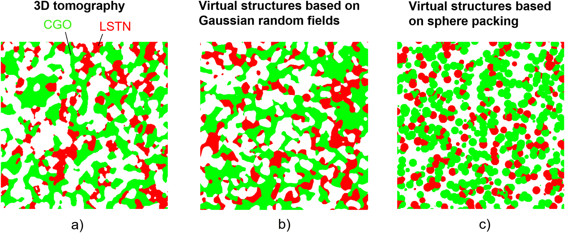 | ||
| Fig. 2 Comparison of a real versus two virtual microstructures (illustrated with 2D orthoslices from 3D structures): (a) segmented tomography data representing a real LSTN–CGO structure with continuous phases, (b) virtual reconstruction of the LSTN–CGO microstructure based on a pluri-Gaussian method (PGM) providing a good match to the real microstructure and (c) virtual reconstruction with sphere packing (not well suited for SOFC electrodes). | ||
In literature, further microstructure models are reported, which are capable to match the properties of real SOFC electrodes. Suzue et al.31 presented a modeling scheme for SOFC anodes based on a stochastic method, where virtual 3D anode microstructures are reconstructed from two-point correlation functions of real 2D images by Monte Carlo sampling of initially randomly assigned voxels. The Lattice Boltzmann Method (LBM) was then used for the performance assessment of the anode. A case study using a graph-based model for the reconstruction of an Ni-YSZ structure was presented by Neumann et al.30 The graph-based model introduced by Neumann et al. in ref. 32 was compared to a pluri-Gaussian method (PGM) with the conclusion that the PGM provides a better match for Ni-YSZ microstructures. Gayon-Lombardo et al.33 and Hsu et al.34 used a generative adversarial network (GAN) to model Ni-YSZ anode microstructures based on 3D training data. The authors reported a very good agreement of the microstructure properties (volume specific interface area, TPB-length and transport properties) between real and virtual microstructures. Sciazko et al.35 reported the generation of 3D-microstructures based on GAN using only 2D training data, which can be advantageous because of the easier acquisition of 2D-images by electron microscopy compared to 3D-data by tomography. The approach was successfully tested for a Ni-CGO SOFC anode.
Stochastic geometry methods are not only used to create virtual microstructures with properties matching to real microstructures. Those methods are then also used for microstructure variation, so that the numerous virtual structures can serve as a basis for data-driven microstructure optimization. For example, Prioux et al.36 constructed a digital twin based on Gaussian random fields for a Ni-YSZ fuel electrode and varied the Ni:YSZ ratio for a fixed porosity of 24%. Thereby, the three-phase boundary (TPB) length, the volume specific surface areas and the M-factor (i.e., relative conductivity) of the Ni- and YSZ-phases were reported for the different compositions and for two grain sizes of Ni. With an electrode-model, the impact of the different microstructures on the electrode performance was then predicted. Thereby, a composition of YSZ![[thin space (1/6-em)]](https://www.rsc.org/images/entities/char_2009.gif) :Ni = 70:30 has been suggested to yield the best performance. Hasanabadi et al.37 presented a method for the optimization of the microstructure of two-phase (a solid and a pore-phase) SOFC MIEC cathodes. Two-point correlation functions were used to manipulate the microstructure. The tortuosity of the solid-phase and the active surface area were used as objective functions to search for the optimal microstructures. Buchaniec et al.38 presented an approach for the optimization of Ni-YSZ anodes by the combination of numerical modeling of transport phenomena, cellular automata and evolutionary algorithms, allowing to determine the phase volume fractions for an optimized performance at different operating conditions. Riazat et al.39 suggested an optimization approach for Ni-YSZ electrodes by investigating a property hull for ionic conductivity, gas diffusivity and TPB-density. A large number of three-phase microstructures was thus generated using a Monte Carlo approach.40,41 These structures were used to train a neural network. A property hull for ionic conductivity, gas diffusivity and TPB-density was then realized applying the neural network and an optimal microstructure was determined by using an objective function with weighting of the three target properties. In a similar study, Tafazoli et al.42 investigated the geometric property hull for infiltrated SOFC-electrodes including gas diffusivity, three-phase and two-phase boundary density.
:Ni = 70:30 has been suggested to yield the best performance. Hasanabadi et al.37 presented a method for the optimization of the microstructure of two-phase (a solid and a pore-phase) SOFC MIEC cathodes. Two-point correlation functions were used to manipulate the microstructure. The tortuosity of the solid-phase and the active surface area were used as objective functions to search for the optimal microstructures. Buchaniec et al.38 presented an approach for the optimization of Ni-YSZ anodes by the combination of numerical modeling of transport phenomena, cellular automata and evolutionary algorithms, allowing to determine the phase volume fractions for an optimized performance at different operating conditions. Riazat et al.39 suggested an optimization approach for Ni-YSZ electrodes by investigating a property hull for ionic conductivity, gas diffusivity and TPB-density. A large number of three-phase microstructures was thus generated using a Monte Carlo approach.40,41 These structures were used to train a neural network. A property hull for ionic conductivity, gas diffusivity and TPB-density was then realized applying the neural network and an optimal microstructure was determined by using an objective function with weighting of the three target properties. In a similar study, Tafazoli et al.42 investigated the geometric property hull for infiltrated SOFC-electrodes including gas diffusivity, three-phase and two-phase boundary density.
In the present study, a workflow for the virtual but realistic microstructure variation based on real tomography data is presented, which is a key-module of the DMD framework reported in Fig. 1. Digital microstructure twins are constructed for a set of real microstructures from LSTN–CGO electrodes. The latter have been reported in a previous publication (Marmet et al.13). The stochastic model makes use of a pluri-Gaussian method (PGM). The microstructure twins are then used as anchor points for a virtual microstructure variation. Thereby, composition and porosity are varied in a wide range. For all the virtual structures of the parameter study, the corresponding microstructure properties are determined using a standardized and automated procedure for microstructure characterization, which was presented in Marmet et al.13 This dataset of microstructure properties for the studied parameter space can be used as a basis for microstructure optimization, in order to fabricate SOFC anodes with improved performances. Thus, the predictions by such DMD methodologies need sufficient accuracy to provide a quantitative correct range. On the other hand, the effort for digital methodologies need to be considerably lower compared to the purely experimental approach in order to accelerate the development process. Moreover, there is only limited benefit if the stochastic modeling exceeds the accuracy level of other uncertainties in the study. Hence, there is a trade-off between accuracy and needed effort for a DMD approach in order to achieve an efficient improvement of SOC electrodes, which will also be discussed in the present publication.
2 Methods and materials
2.1 Overview of the concept for digital twin construction of three-phase microstructures
In this section, an overview is provided for the workflow of virtual microstructure generation and variation by stochastic modeling based on the pluri-Gaussian method (PGM). In general, two different approaches can be distinguished: (a) a rather complex expression is used to model the correlation function of the Gaussian random field. This expression includes several fit-parameters, but the angles between the sectors of the thresholding plane remain constant. Examples are presented by Abdallah et al.29 and Neumann et al.30,43 (b) A rather simple expression is used to model the correlation function (typically a Gaussian distribution with only one fit-parameter representing the structure size). However, the angles between the domains of the thresholding plane are variable and can thus be used for adaptation of the microstructure properties. Examples of this type are presented by Moussaoui et al.28 and Prioux et al.36 In the present work, we follow the second approach (b), whereby we are using only two parameters for the two Gaussian correlation functions, and five additional parameters for the thresholding, as will be described in Section 2.2. To match the microstructure properties of the real tomography data described in Marmet et al.,13 a data-driven approach is used with a systematic variation of the threshold angles for different porosities and compositions. Thereby, the same standard deviation is used in the Gaussian model for the correlation functions of both solid phases (i.e., LSTN and CGO). This can be justified, since the characteristic particle sizes and size distributions are very similar for both phases in all the LSTN–CGO electrodes that are studied in this contribution. The parameter set for the digital microstructure twin is then obtained by interpolation of the database, which is obtained by the systematic variation of construction parameters (e.g., threshold angles). Therewith, a good match of the interface areas and the TPB-length can be achieved. However, the relative conductivities of the virtual microstructures show considerable deviations compared to the conductivities of the real microstructures from tomography. To improve the match of the relative conductivities, the geometry of the solid phases in the digital twins are modified with morphological operations. The digital twin construction is described in further detail in Section 2.3. The main benefit of the digital microstructure twins is the possibility to construct realistic virtual microstructures, which have not yet been realized experimentally. However, it is not obvious, how the set of construction parameters evolve upon a parameter variation. Therefore, these construction parameters are interpolated and extrapolated between and upon the three realized digital twins as reported in Section 3.4.2.2 Structure generation based on pluri-Gaussian random fields
The structure generation based on pluri-Gaussian random fields used in this work is implemented as a Python app (subsequently called – PGM-app). It is implemented in GeoDict in order to obtain a closed workflow, whereby stochastic microstructure generation can be combined with a fully automated and standardized characterization procedure. The latter was presented in Marmet et al.13 This PGM-app is published on Zenodo44 from where it can be downloaded and then be used within GeoDict. The graphical user interface (GUI) of the PGM-app is reported in Section B of the ESI.† Moreover, a modified version of this app was released in the GeoDict software package (GeoDict release 202345) as a so-called GeoApp. The implementation follows closely the methods presented by Moussaoui et al.28 and shall not be repeated here in detail. Instead, a conceptional overview of the method will be presented in the following with a focus on the input parameters of the PGM-app and how these parameters are reasonably chosen to model microstructures with specific properties. Fundamental information about the method can e.g., be found in the book of Lantuéjoul.22The principle of structure generation with the pluri-Gaussian method (PGM) for three-phase structures is illustrated in Fig. 3. The method is based on two statistically independent Gaussian random fields GRF1 and GRF2, one for each solid phase. The two Gaussian random fields (GRF) are then combined using threshold operations to obtain three phases (two solid phases and one pore-phase) with defined phase volume fractions and wetting behaviour. Thus, many different structures can be obtained for the same set of two GRFs by using different threshold parameters. The model parameters for the two GRFs are reported in Table 1 and the model parameters for the threshold operations are reported in Table 2.
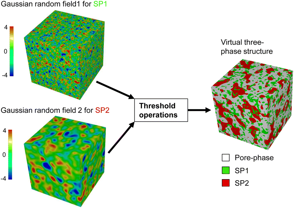 | ||
| Fig. 3 Illustration of virtual structure generation with the pluri-Gaussian method (PGM). A microstructure consisting of two solid phases and a pore-phase is generated by combining two Gaussian random fields for both solid phases. The phase volume fractions and the wetting behaviour of the solid phases can be controlled with specific threshold operations. | ||
| Description | Parameter | Unit |
|---|---|---|
| Number of voxels in X-direction | NX | Voxel |
| Number of voxels in Y-direction | NY | Voxel |
| Number of voxels in Z-direction | NZ | Voxel |
| Voxel size | l vox | m |
| Standard deviation (characteristic length) of the Gaussian random field 1 | SDGRF1 | Voxel |
| Standard deviation (characteristic length) of the Gaussian random field 2 | SDGRF2 | Voxel |
| Random seed for GRF 1 | RSGRF1 | — |
| Random seed for GRF 2 | RSGRF2 | — |
| Filter factor for GRF 1 | k Filter,GRF1 | — |
| Filter factor for GRF 2 | k Filter,GRF2 | — |
| Description | Parameter | Unit |
|---|---|---|
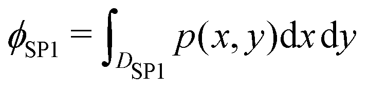
| Solid volume fraction SP1 | ϕ SP1 | — |
| Solid volume fraction SP2 | ϕ SP2 | — |
| Angle between the domains DSP1 and DSP2 | α | ° |
| Angle between the domains DSP2 and Dpore | β | ° |
| Angle between the domains Dpore and DSP1 | γ | ° |
| Tolerance for the solid volume fractions ϕSP1 and ϕSP2 | δ ϕ | % |
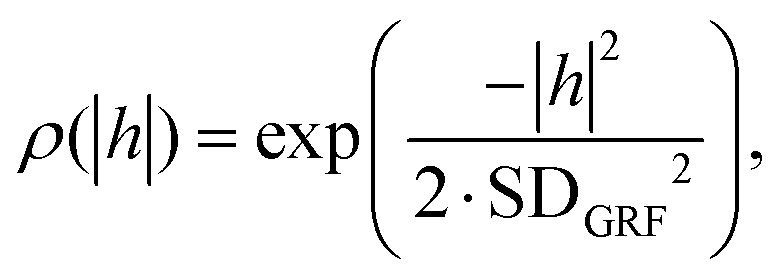
The Gaussian random field can be generated by the convolution of an uncorrelated Gaussian random noise with a normalized and symmetric weight function, which can be interpreted as the filtering of the uncorrelated random noise with the weight function.28 With this operation, the requested spatial correlation is obtained, as described by the correlation function ρX(h):
| ρX(h) = cov(GX(z),GX(z + h)), | (1) |
 | (2) |
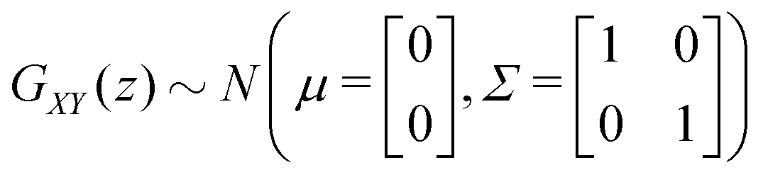
| GXY(z) = {GX(z);GY(z)} | (3) |
 whose probability density function p(x,y) is given by:
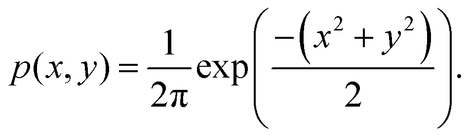 | (4) |
In order to obtain a virtual microstructure with three phases (i.e., solid-phase 1 = SP1, solid-phase 2 = SP2 and pore-phase), a specific numerical realization of a pluri-Gaussian random field GXY(z) using GeoDict has to be segmented (note that a reproducible realization can be obtained by specifying the corresponding random seeds RSGRF1 and RSGRF2). The segmentation is performed by partitioning of p(x,y) in three domains DSP1, DSP2 and Dpore as illustrated in Fig. 4. The sets of voxels ΩSP1, ΩSP2 and Ωpore belonging to the corresponding phases are thus obtained by thresholding GXY(z) with the three domains as follows:
| ΩSP1 = {z:GXY(z)∈DSP1} | (5) |
| ΩSP2 = {z:GXY(z)∈DSP2} | (6) |
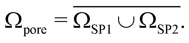 | (7) |
 | (8) |
 | (9) |
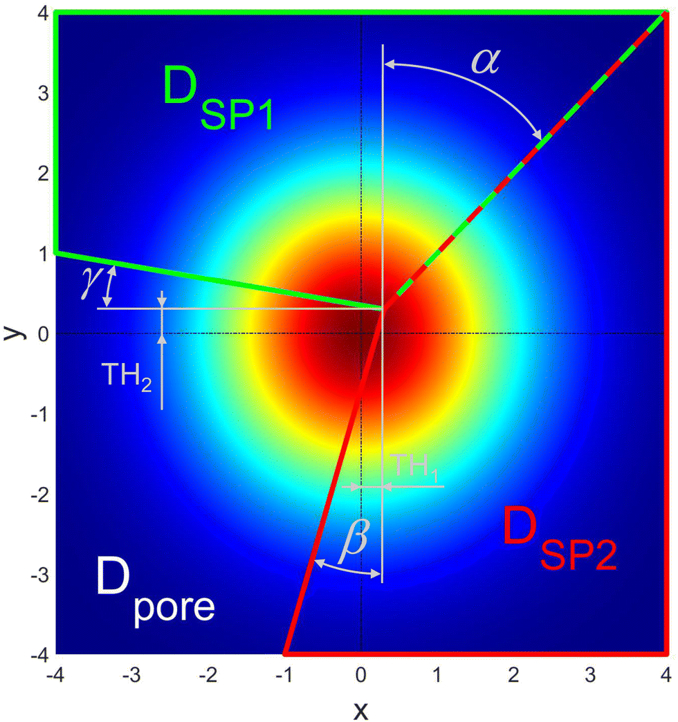 | ||
| Fig. 4 Thresholding plane with indication of the domains for solid-phase 1 (SP1), solid-phase 2 (SP2) and pore-phase defined by the angles α, β and γ and the threshold parameters TH1 and TH2. | ||
A known issue of the PGM (e.g., ref. 29) is that the thresholding of the Gaussian random fields result in an irrelevant noise at the interfaces of the phases. Therefore, an option is implemented to filter the Gaussian random fields with a low-pass Gaussian filter in order to suppress these interface artefacts as e.g., suggested by Abdallah et al.29 This noise-filtering option is reported in Section A of the ESI.† Note that a filter factor kFilter = 0.025 (Table 1) is a good default choice, which does not need to be adapted in general.
In summary, the PGM procedure includes two major steps: (1) the generation of two independent Gaussian random fields (GRF) and (2) the thresholding of these GRFs in order to get a defined three-phase structure. If a structure with different characteristic particle sizes for the two solid phases shall be generated, the standard deviations of the two corresponding Gaussian random fields need to be chosen accordingly, as illustrated in Fig. 3. With appropriate thresholding operations, the resulting structures can be varied in a large range by only changing the threshold operations for the same set of two Gaussian random fields. Especially, the phase volume fraction and the wetting behaviour of the phases can be varied very easily and efficiently. The possibilities of structure variations with the thresholding operations shall be illustrated in the following. For these examples, the same characteristic size (i.e., standard deviation) for the Gaussian random fields will be used for solid-phase 1 (SP1) and solid-phase 2 (SP2). In Fig. 5, threshold parameters to achieve different phase volume fractions and compositions are illustrated. We define a reference case as shown in Fig. 5(a), where all the domains DSP1, DSP2 and Dpore meet in the centre. The sector Dpore occupies one fourth of the plane, which results in porosity of ε = 25%. The two domains DSP1 and DSP2 occupy the rest of the plane with equal shares, which results in the solid-phase volume fractions ϕSP1 = ϕSP2 = 37.5%. If for example, a higher porosity of ε = 50% shall be realized while still maintaining equal solid volume fractions, the corresponding sector for the pore-phase can be enlarged in x- and y-direction to the same extent, which is illustrated in Fig. 5(b). Note that the phase volume fractions correspond to the integral values of the probability density function over the domains as stated in eqn (8) and (9). To achieve a lower porosity, the sector would need to be reduced accordingly. To change the composition of the solid phases to e.g., SP1:SP2 = 70:30, the domain DSP1 can be enlarged and the domain DSP2 reduced, resulting in the defined composition and constant porosity of ε = 25% as illustrated in Fig. 5(c).
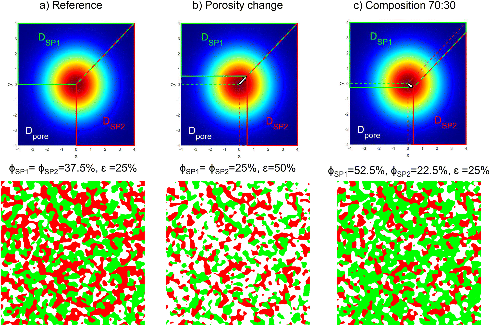 | ||
| Fig. 5 Illustration of the threshold parameters in order to achieve different phase volume fractions and compositions: (a) reference structure with a porosity of ε = 25% and equal solid-phase volume fractions ϕSP1 = ϕSP2 = 37.5%, (b) structure with higher porosity of ε = 50% and with equal solid-phase volume fractions ϕSP1 = ϕSP2 = 25% and (c) structure with solid-phase fractions of SP1:SP2 = 70:30 and with an unchanged porosity of ε = 25%. | ||
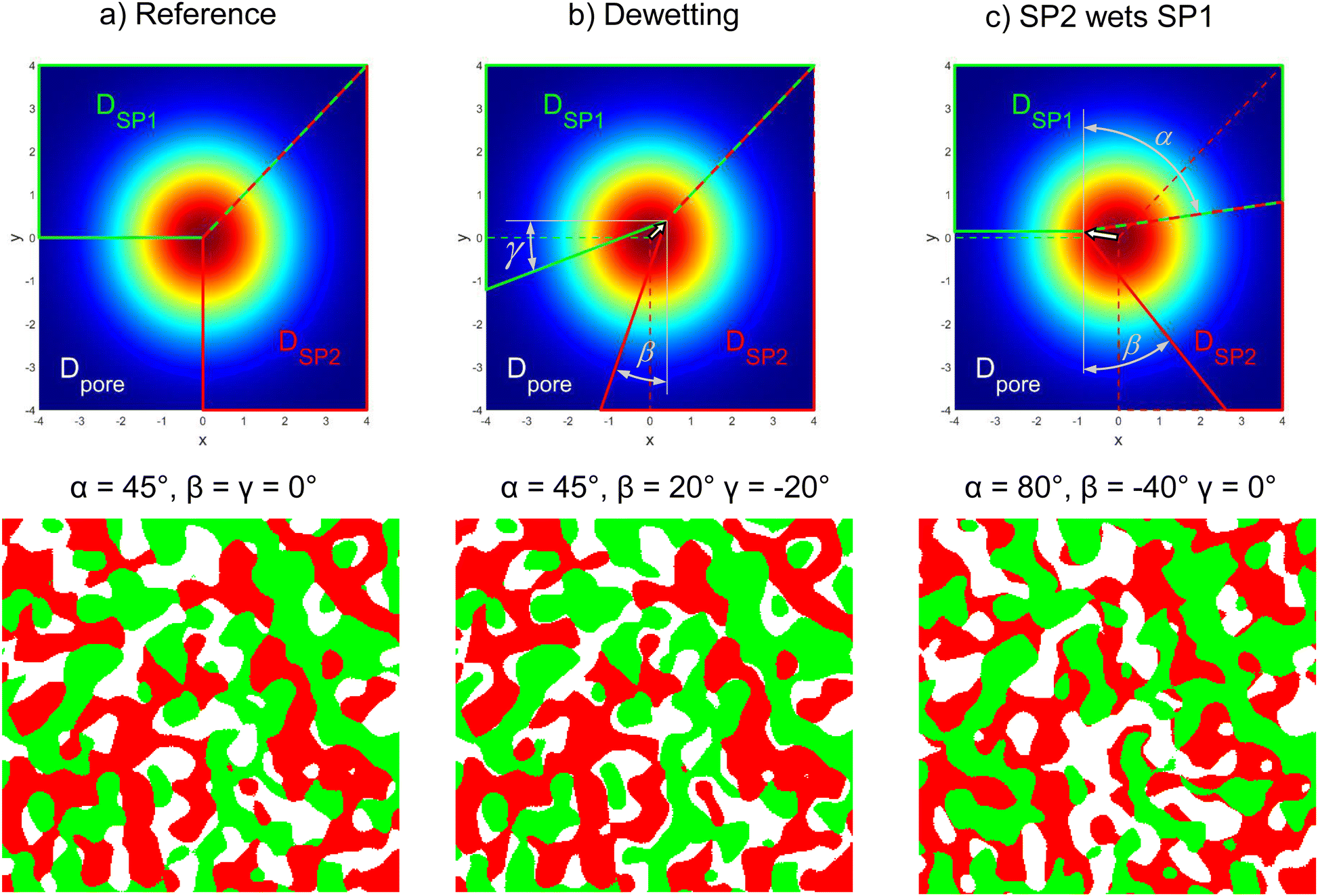
In addition to the composition and porosity, also the wetting behaviour of the two solid phases can be modified in a controlled way. This is achieved by changing the angles between the domains of the phase assignments as illustrated in Fig. 6. The corresponding volume specific interface areas for the three exemplary structures are reported in Fig. 7. In Fig. 6(a), the reference structure with α = 45°, β = 0° and γ = 0° is shown, where a cutout at higher magnification is used for better visualization. The reference structure exhibits (almost) identical volume specific interface areas for pore–SP1, pore–SP2, and SP1–SP2 (Fig. 7(a)). In Fig. 6(b) a dewetting example is shown with α = 45°, β = 20° and γ = −20°, which represents the physical case where the solid phases do not like to touch each other. As a result (Fig. 7(b)), the volume specific interface areas pore–SP1 and pore–SP2 are significantly larger and the solid-phase interface SP1–SP2 is significantly lower compared to the reference structure. In Fig. 6(c), an example with α = 80°, β = −40° and γ = 0° is shown, where SP2 wets SP1. Consequently, the volume specific interface area pore-SP1 is less than half the value of the reference, while the value for pore-SP2 is significantly higher (Fig. 7(c)). Moreover, the volume specific interface area SP1–SP2 is enlarged by 50%. In the literature,28 there is no analytical expression available yet for the relation between the threshold angles and the volume specific interface areas. Therefore, in this work these relations will be captured empirically by performing a systematic parameter variation.
 | ||
| Fig. 6 Visualization of thresholding operations and their impact on the wetting behaviour: (a) reference structure with neutral wetting behaviour, (b) example for a dewetting and (c) example for a wetting of the solid-phases. | ||
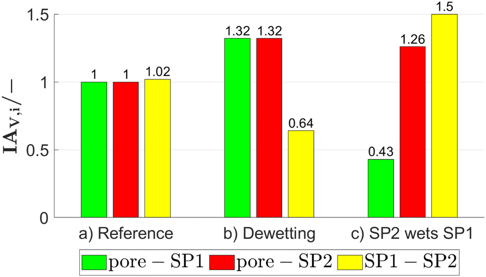 | ||
| Fig. 7 Volume specific interface areas for the exemplary structures of Fig. 6. Note that the values are normalized to the volume specific pore–SP1 interface area of the reference structure (a). | ||
If a structure with two different characteristic lengths shall be generated, the standard deviations of the two corresponding Gaussian random fields need to be chosen accordingly as illustrated in Fig. 3. It has to be emphasized that the variation of thresholding angles and associated change in the wetting behaviour also affects the morphology of the pore-phase and associated pore size distribution. This effect is particularly strong, if two different characteristic phase sizes are used, which is illustrated in Fig. 8. Thereby two different threshold settings with different phase sizes (i.e., SDGRF1 = 10vox and SDGRF2 = 30vox) are compared with the reference structure that is characterized by equal phase sizes. For all three structures, the phase volume fractions are identical, but the pore morphology is different. The mean radius of the pore-phase rmax,pore,cont (i.e., r50 of the continuous pore size distribution see Münch and Holzer47) and the simulated gas permeability κsim (as described in Marmet et al.13) are reported in the captions. For both structures in (b) and (c), an increase in the size of SP2 also leads to an increase of the pore size and associated gas permeability. However, for the structure with standard threshold angles (α = 45°, β = 0°, γ = 0°) in Fig. 8(b), the smaller phase (SP1, green) is not strongly bound to the interface with SP2 and thus it extends markedly into the pore-space. This results in a limited increase of the pore size of only about 40% compared to the reference structure (Fig. 8(b)), despite the fact that one solid-phase is enlarged by a factor of three. For the example reported in Fig. 8(c), the threshold parameters (α = 45°, β = −20°, γ = 60°) are chosen such that the smaller phase (SP1, green) is preferably wetting the larger phase (SP2, red). Consequently, the smaller phase (green) is predominantly located along the interface with the larger phase (red) and, therefore, it does not extend significantly into the pore-phase. As a result, the pore size is enlarged by more than a factor of two compared to the reference case. These different morphologies directly affect the transport properties of the pore-phase. For example, the gas permeability for the structure in Fig. 8(c) is 75% higher compared to the structure in Fig. 8(b).
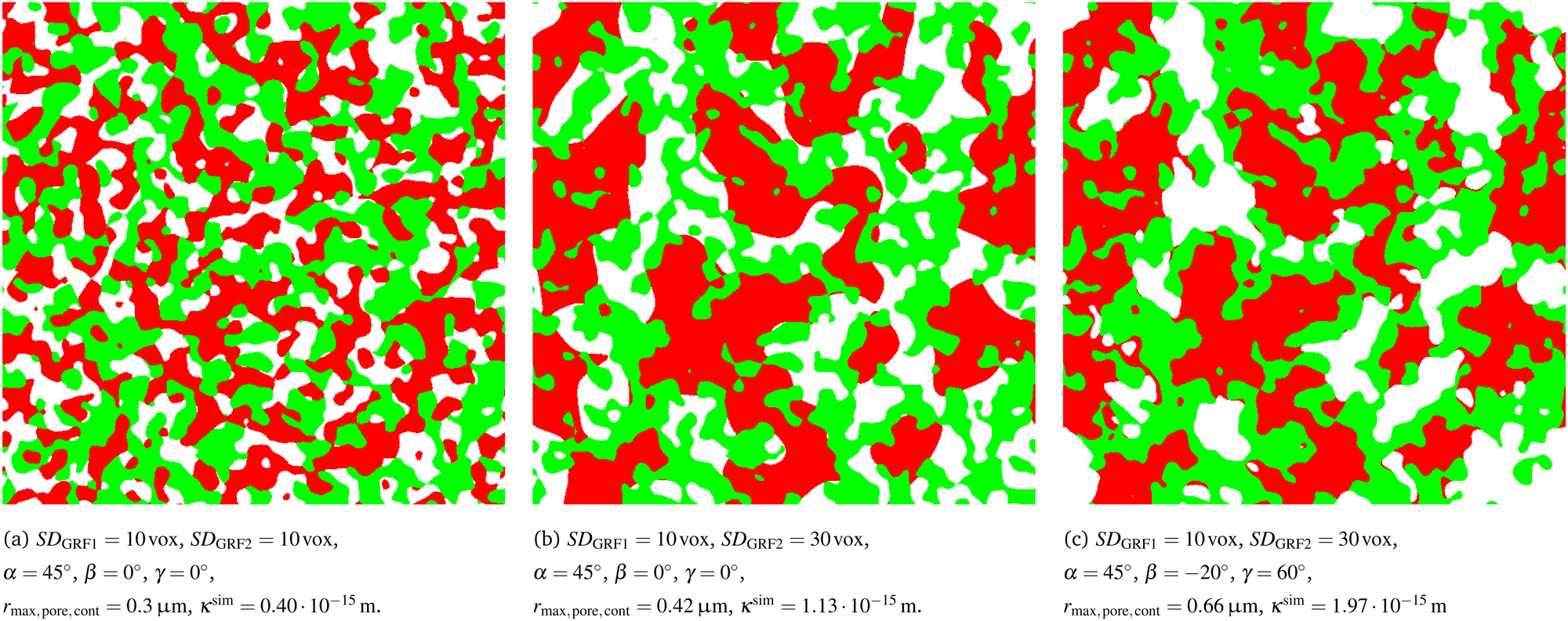 | ||
| Fig. 8 Structures with different characteristic phase sizes and different wetting behaviours: (a) reference structure with equal phase sizes. (b) Structure with different phase sizes: Note that the smaller phase (SP1, green) forms numerous fingers that extend into the pore-phase. (c) Structure with different phase sizes: Note that due to a different wetting behaviour (compared to (b)), the smaller phase (SP1, green) is more confined to the vicinity of the larger phase (SP2, red), which results in larger pores. The mean radius of the pore-phase rmax,pore,cont and the simulated gas permeability κsim are reported for the different structures. | ||
2.3 Digital microstructure twin based on pluri-Gaussian random fields
A relevant application of the PGM is the construction of a digital microstructure twin, i.e., a virtual microstructure model with almost the same properties as a real reference structure (e.g., from tomography) with the ability for parameter variation. There are different possibilities to match the digital twin to the real structure. Neumann et al.30 fitted a parametric model for the two-point coverage probability functions with two parameters for each solid phase. Thereby, they used constant shapes (i.e., constant angles) for the thresholding domains. In another work, Neumann et al.43 fitted two parameters for the Gaussian correlation function (one for each GRF), and a factor accounting for the correlation of the phases, again using constant shapes for the thresholding domains. However, in the present study, the shapes of the thresholding domains are variable. Presently, there is no analytical expression available28 in literature to describe the relations between the angles α, β and γ in Fig. 4 and the microstructure properties. Hence, the fitting of the digital microstructure twins is achieved based on a microstructure database, which is illustrated in Fig. 9. Thereby, the angles α, β and γ are systematically varied for different porosities and compositions using the same set of two GRFs. This parametric variation results in the realization of 1575 different virtual microstructures (see also Section F.2 of the ESI,† for further details). This database can be constructed with reasonable computational effort, because only the threshold operations and not the GRFs need to be varied. Subsequently, the relevant microstructure properties are determined for these structures using the characterization app.13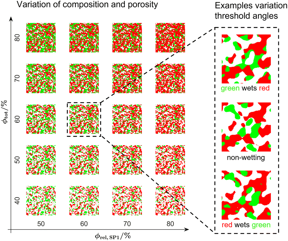 | ||
| Fig. 9 Visualization of the PGM-structure library for the fitting of the construction parameters including 1575 realized virtual microstructures. Note that for the variation of the threshold angles α, β and γ only three examples of a much larger variation are shown. | ||
The procedure to construct a digital microstructure twin is illustrated in Fig. 10 and briefly described in the following (see also Section F of the ESI†):
 | ||
| Fig. 10 Workflow for the construction of a digital microstructure twin for a corresponding real structure, e.g., from tomography. (1) Characterization of the real structure, (2) determination of the PGM parameters for matching microstructure properties, (3) generation of an initial PGM structure and (4) optimization of the relative conductivities with morphological operations. | ||
1. Standard characterization of the segmented real structure from 3D tomography with the characterization-app.13
2. Interpolation of the structure database to determine appropriate threshold angles α, β and γ, which match the volume specific interface areas and TPB-length of the real structure. First, the database is interpolated to the given phase volume fractions of the real structure (i.e., composition and porosity, respectively). Therewith, a normalized sub-dataset relating the threshold angles with the selected microstructure properties (i.e., volume specific interface areas and TPB-length) is available for fixed phase volume fractions. Second, the threshold angle set with the best match to the real structure is determined based on error-functions. Thereby, also the voxel size is scaled, while the number of voxels for the standard deviations of the Gaussian random fields are held constant at SDGRF1 = SDGRF2 = 10voxels.
3. Generation of an initial PGM-structure with the correct porosity and composition and matching volume specific interface areas and TPB-length using the determined threshold angles (α, β and γ) and the appropriate voxel size from step 2.
4. Optimization of the relative conductivities in order to obtain a closer match to the real structures. Thereby, a sequence of morphological operations (erode and dilate) is applied on the solid-phases. Especially the connection between the features within the individual solid-phases are manipulated to adapt the relative conductivities, as illustrated in Fig. 11. Typically, the relative conductivities of the pure PGM structures are too high and thus the connectivity between the structure features needs to be reduced. The needed numbers of involved voxels (nvox,mod,SP1 and nvox,mod,SP2 in Table 3) for the morphological operations are determined in an automated iterative process. Thereby, the relative conductivities of the PGM structure after the morphological operations are computed and compared with respect to the target values of the real structure. Either the relative single-phase conductivities (e.g., for Ni-YSZ) or the composite conductivities (e.g., for LSTN–CGO) can be matched, depending on the material system. Note that the volume fractions are no more precisely defined by eqn (8) and (9) after application of the morphological operations. However, the volume fractions are conserved within a narrow range of typically 0.1%.
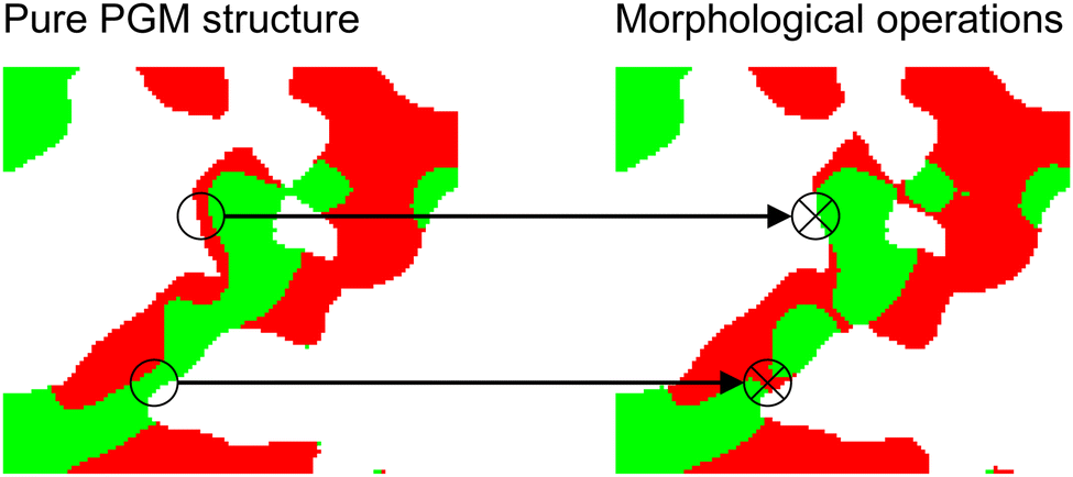 | ||
| Fig. 11 Illustration of the effect of the morphological operations: Starting from the pure PGM microstructure (step 3 in Fig. 10), the connection of the features within the individual solid-phases are reduced (step 4 in Fig. 10). Therewith, the composite conductivities can be matched closer to the real structures from tomography. | ||
| Description | Parameter | Unit |
|---|---|---|
| Number of voxels used for the morphological operations on SP1 | n vox,mod,SP1 | Voxel |
| Number of voxels used for the morphological operations on SP2 | n vox,mod,SP2 | Voxel |
| Switch for morphological operations: if enabled (Y), SP1 is dilated at the expense of SP2 and if disabled (N), SP1 is eroded while SP2 is dilated | Switch 1 | Y/N |
With the fitting procedure of step 2 in Fig. 10, a good match of the interface areas and the TPB-length can be achieved (see also results Section 3.3). However, the relative conductivities show larger deviations. Typically, the relative conductivities of the virtual structures are too high compared to the real structures. The same behaviour can be observed in the studies of Moussaoui et al.28 and Neumann et al.,30 where the relative conductivities of the virtual structures show a deviation around 20%. Thus, this a general issue for the PGM, which also cannot be fully resolved by using and fitting a more complex model for the correlation function, as employed by Neumann et al.30 This is most probably because the correlation function is a statistical property of how the phase is distributed in space and hence is rather insensitive to local morphological details like bottlenecks and phase network connectivity of individual features, which, however, strongly influence the relative conductivity. Thus, the morphological operations described in step 4 in Fig. 10 are a valuable option to improve the match of the relative conductivities.
Note that the current database of virtual structures is based on parameter variations that are created with the same standard deviation for the two GRFs. Consequently, the fitting procedure only provides appropriate results for three-phase structures with similar characteristic phase sizes. Fortunately, this is the case for the used set of LSTN–CGO electrodes as confirmed in a previous publication.13 If this was not the case, the database would need to be extended to different characteristic phase sizes. Alternatively, the approach could be combined with additional methods like machine learning or more complex models for the correlation functions of the Gaussian random fields.
A detailed documentation of the entire workflow to construct digital microstructure twins with properties that show a good match with the corresponding real structures is reported in Section F of the ESI.†
3 Results
In this result section, the methods introduced in Section 2 are applied to perform a parametric microstructure study by stochastic modeling of LSTN–CGO anodes. In Section 3.1 the computational efficiency for the PGM structure generation is estimated. In Section 3.3, the construction and characterization of the digital microstructure twins are presented. Their properties are compared and matched with those of three real microstructures of experimental LSTN–CGO anodes using the procedure described in Section 2.3. In Section 3.4, the systematic variation of virtual PGM microstructures is described. For this purpose, the digital microstructure twins from Section 3.3 are used as anchor points for a parametric study. The corresponding microstructure properties for these microstructure variations are reported in Section 3.5.3.1 Computation times with PGM and sphere-packing
As an estimate for the computational efficiency, the computation times to generate PGM structures and sphere-packing structures are compared for three examples of each method with the same structure size of 6003 voxels. The tests are documented in Section C of the ESI,† in detail and the results are summarized in the following:• The construction times with PGM were around 6 minutes for each of the three structures and thus almost independent of the phase volume fractions.
• In contrast, the construction times for the sphere-packing structures (using the GrainGeo module of the GeoDict software package) were between 25 minutes and 8.7 hours and hence, strongly depend on the porosity (i.e., higher construction times for lower porosities).
• These examples clearly illustrate the higher efficiency of the PGM approach compared to the sphere-packing method.
3.2 LSTN–CGO electrodes: materials processing, fabrication and imaging
The workflow for the digital twin construction reported in Section 2.3 shall be applied to a dataset of three microstructures obtained by FIB-SEM tomography. These three microstructures represent variations of experimentally fabricated SOFC fuel electrodes consisting of CGO and LSTN with different compositions and porosities. Visualizations of the three LSTN–CGO microstructures are provided in Fig. 12 (top row). In a separate paper, we provided a detailed description of the properties of raw materials and powders, the fabrication procedure for the electrodes, as well as the 3D imaging methodology (see Marmet et al.,13 including the corresponding ESI,† Section F). Furthermore, the entire fabrication process of such titanate-CGO anodes was also described in another publication (Burnat et al.12). Nevertheless, a brief summary of the experimental data and procedures shall be presented here as follows. Button cells are produced by screen-printing of LSTN–CGO pastes on a commercial solid electrolyte from Kerafol (scandium-stabilized Zr-oxide). The used LSTN material (more precisely: La0.3Sr0.55Ti0.95Ni0.05O3−δ perovskite, see also Burnat et al.12) was developed in an SNF-project (NRP70, Energy Turnaround) and further information can be found here.48 For CGO (i.e., Gd0.1Ce0.9O1.95), commercial powder from H. C. Stark was used. The BET measurements reveal SSA values of 21.2 m2 g−1 (i.e., mean particle diameter around 40 nm) for the reprocessed CGO powder and 13.3 m2 g−1 (i.e., mean particle diameter around 80 nm) for the LSTN powder. The screen-printed LSTN–CGO layer was then sintered at a temperature of 1250 for 2 h. The intrinsic conductivities of the two MIEC materials are estimated from available literature data as reported in Table 4. For CGO10 (i.e., Ce-oxide with 10% doping of Gd), relatively precise conductivity data are available.49 However, for LSTN the experimental results are less precise so that only the order of magnitude can be estimated.10,50 Based on the available data, it is justified to make the assumption that the intrinsic electronic conductivity of LSTN is 10 times higher compared to CGO, and the intrinsic ionic conductivity of LSTN is 10 times lower compared to CGO. Hence, in a MIEC anode consisting of LSTN and CGO, both phases will contribute to the transport of both charge carriers. The resulting effective transport property of composite MIEC electrodes is called composite conductivity (see Marmet et al.13). This composite conductivity is an important advantage of MIEC anodes, compared to anodes consisting of single-phase conductors. Moreover, the harmful degradation phenomena associated with Ni (see also introduction Section 1) can be avoided by the replacement of Ni with a perovskite. In fact, a high robustness against carbon coking, sulphur poisoning and redox-cycling is reported for many different perovskites and other MIEC materials.9 The used LSTN–CGO fuel electrode represents a specific example of this promising materials concept for fully ceramic electrodes.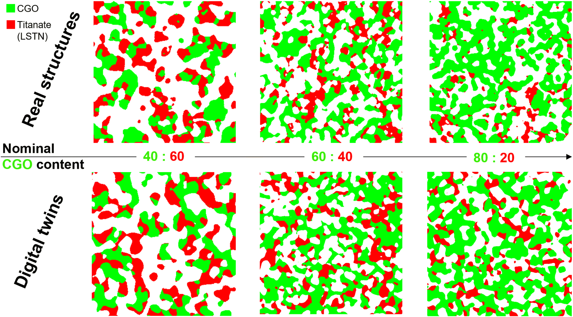 | ||
| Fig. 12 Orthoslices for visual comparison of the real LSTN–CGO anode microstructures captured by tomography (top row) with the corresponding digital microstructure twins (bottom row). The widths of the image windows is 3 μm for CGO40-LSTN60 and 3.84 μm for CGO60-LSTN40 and CGO80-LSTN20. | ||
3.3 Digital microstructure twins for a set of three LSTN–CGO structures
The workflow for the digital twin construction reported in Section 2.3 has been applied on the LSTN–CGO dataset, summarized in the previous Section 3.2. The corresponding results shall be presented in this section.In Fig. 12, a visual comparison of the real structures and their corresponding digital microstructure twins is provided. The visual comparison reveals a good agreement. However, the sample with the composition CGO:LSTN = 80:20 shows some inhomogeneities for the LSTN-phase, which is not captured by the digital twin. It must be emphasized that the individual structural features are not expected to be identical. However, the morphology of the real and corresponding virtual microstructure should be characterized by the same (or at least very similar) statistics, especially with respect to the most important microstructure properties. In Table 5, selected microstructure properties, which are particularly important for the parametrization of an electrode model for performance prediction, are compared for the three real structures and their corresponding digital microstructure twins. For all three couples of real and corresponding virtual structures, the volume fractions match well, typically with a deviation of within 0.1%. The deviations of phase volume fractions are predominantly caused by morphological operations after the PGM construction. The match of volume specific interface areas is typically within 2%. Thereby, the largest deviations are reported for the volume specific SP1–SP2 interface areas (maximal deviation of 2.85%). The TPB-lengths are typically matched within 3%, expect for the LSTN20-CGO80 microstructure, where a larger deviation of 11.83% is observed. This mismatch can be attributed to some inhomogeneities that are present in the experimental sample (see also Marmet et al.13), which are not captured by the digital microstructure twin.
| Sample | LSTN60-CGO40 | LSTN40-CGO60 | LSTN20-CGO80 | ||||||||
|---|---|---|---|---|---|---|---|---|---|---|---|
| Description | Variable | Unit | Tomo | DT | Dev. | Tomo | DT | Dev. | Tomo | DT | Dev. |
| Material for SP1 | Material SP1 | — | CGO | CGO | — | CGO | CGO | — | CGO | CGO | — |
| Material for SP2 | Material SP2 | — | LSTN | LSTN | — | LSTN | LSTN | — | LSTN | LSTN | — |
| Voxel length | l vox | nm | 10 | 9.16 | — | 10 | 7.67 | — | 10 | 7.95 | — |
| Number of voxels in X-direction | NX | vox | 300 | 600 | — | 384 | 600 | — | 384 | 600 | — |
| Number of voxels in Y-direction | NY | vox | 384 | 600 | — | 384 | 600 | — | 384 | 600 | — |
| Number of voxels in Z-direction | NZ | vox | 384 | 600 | — | 157 | 600 | — | 384 | 600 | — |
| Total porosity | ε | — | 0.5163 | 0.5163 | −0.01% | 0.4439 | 0.4439 | −0.02% | 0.3871 | 0.3872 | 0.04% |
| Total solid volume fraction | ϕ tot | — | 0.4837 | 0.4837 | 0.01% | 0.5561 | 0.5561 | 0.01% | 0.6129 | 0.6128 | −0.03% |
| Solid volume fraction SP1 | ϕ SP1 | — | 0.2355 | 0.2352 | −0.11% | 0.3665 | 0.3667 | 0.06% | 0.4799 | 0.4798 | −0.03% |
| Solid volume fraction SP2 | ϕ SP2 | — | 0.2482 | 0.2485 | 0.14% | 0.1895 | 0.1894 | −0.07% | 0.1330 | 0.1330 | −0.01% |
| Volume specific interface area pore-SP1 | IAV,pore-SP1 | μm2 μm−3 | 3.295 | 3.295 | 0.03% | 5.075 | 5.087 | 0.24% | 5.688 | 5.704 | 0.28% |
| Volume specific interface area pore-SP2 | IAV,pore-SP2 | μm2 μm−3 | 3.813 | 3.819 | 0.13% | 3.438 | 3.397 | −1.20% | 2.583 | 2.611 | 1.08% |
| Volume specific surface area of pores | S V,pore | μm2 μm−3 | 7.108 | 7.114 | 0.08% | 8.513 | 8.484 | −0.34% | 8.271 | 8.314 | 0.53% |
| Volume specific interface area SP1 - SP2 | IAV,SP1–SP2 | μm2 μm−3 | 2.966 | 2.902 | −2.16% | 2.922 | 3.006 | 2.85% | 2.524 | 2.465 | −2.34% |
| Volume specific three-phase boundary (TPB) length | L V,TPB | μm μm−3 | 67.894 | 69.591 | 2.50% | 81.002 | 82.141 | 1.41% | 80.185 | 70.696 | −11.83% |
| Relative single-phase conductivity SP1 | σ simrel,SP1 | — | 0.0204 | 0.0291 | 43.00% | 0.1670 | 0.1608 | −3.72% | 0.1850 | 0.2307 | 24.69% |
| Relative single-phase conductivity SP2 | σ simrel,SP2 | — | 0.0345 | 0.0473 | 37.04% | 0.0113 | 0.0121 | 7.40% | 0.0014 | 0.0045 | 227.99% |
| Relative electronic composite conductivity (λeon = 0.1) | σ rel,eon,comp | — | 0.0848 | 0.0880 | 3.86% | 0.0793 | 0.0821 | 3.55% | 0.0724 | 0.0698 | −3.60% |
| Relative ionic composite conductivity (λion = 0.1) | σ rel,ion,comp | — | 0.0689 | 0.0823 | 19.44% | 0.2044 | 0.1965 | −3.88% | 0.2285 | 0.2607 | 14.11% |
| Relative gas diffusivity | D simrel | — | 0.3249 | 0.2930 | −9.81% | 0.1539 | 0.1862 | 21.00% | 0.1822 | 0.1703 | −6.57% |
| Gas permeability | κ sim | m2 | 4.382 × 10⁻¹⁶ | 4.225 × 10⁻¹⁶ | −3.59% | 1.303 × 10⁻¹⁶ | 1.504 × 10⁻¹⁶ | 15.41% | 1.148 × 10⁻¹⁶ | 1.098 × 10⁻¹⁶ | −4.38% |
| Knudsen characteristic length | d Kn,pore | μm | 0.1868 | 0.1889 | 1.14% | 0.1318 | 0.1373 | 4.20% | 0.1197 | 0.1216 | 1.58% |
| Knudsen relative diffusivity | D simKn,rel,meanXYZ | — | 0.2232 | 0.2192 | −1.80% | 0.1046 | 0.1284 | 22.78% | 0.1261 | 0.1215 | −3.64% |
The relative ionic and electronic composite conductivities (see definition in Marmet et al.13) exhibit relatively large deviations up to 20%. Despite the corrections with morphological operations, it is challenging to match the relative ionic and electronic composite conductivities at the same time because of the complex interplay between the two solid phases (i.e., the morphologies and associated properties of the two solid phases cannot be changed independently). However, the deviations are still in a good range for the current application. Note that the single-phase conductivities can be matched more easily with the morphological operations, and thus, it would be possible to achieve a better match. However, this would be at the expense of higher deviations for the composite conductivities. Since, the composite conductivity is more relevant for the performance prediction with the electrode model, the optimization of the relative composite conductivities is given higher priority than the single-phase conductivities. Therefore, the non-optimized single-phase conductivities show deviations up to typically 50%. Note that the relative deviations are especially large for very low M-factors near the percolation threshold. For example, the relative single-phase conductivity of SP2 (LSTN) of the LSTN20-CGO80 structure shows a relative deviation of 228%, which corresponds to an absolute deviation of 0.0031 (note: the relative conductivity is a dimensionless parameter).
For the transport properties of the pore-phase, higher deviations are expected in general, because this phase is not directly modelled with PGM. The pore-phase is thus simply the complementary space, which is left over after model-based realization of the solid phases. The gas permeabilities of virtual and real microstructures match within 15%. The relative bulk and the Knudsen diffusivities match within approximately 20%. The fit of Knudsen characteristic lengths is even within 5%. These relatively good agreements of the pore-phase properties can be attributed to the fact that the structures have quite high porosities. As a consequence, the transport properties are less sensitive to small morphological changes, in contrast to structures with very low porosities with a pore-phase close to the percolation threshold. A more detailed comparison of the digital microstructure twin with the real structure is reported for the LSTN60-CGO40 sample in Section F.9 of the ESI.†
3.4 Set of construction parameters for the realization of three microstructure twins and interpolation/extrapolation rules for parameter variation
The construction parameters for the three digital microstructure twins are reported in Table 6. These construction parameters can be understood as sets of values that can be used for the realization of a specific virtual 3D microstructures with properties that closely match with those of the corresponding real, experimental microstructures (i.e., tomography data). Between and beyond the values of these twin construction parameters it can now be systematically interpolated and extrapolated in order to perform realistic variations of the microstructures. Thereby, virtual microstructures can be realized also for parameter values, which have not yet been realized experimentally. In our example, a linear interpolation of the construction parameters is applied. For the extrapolation, constant construction parameters of the nearest digital twin structure are used (e.g., wetting angles and parameters for morphological processes) and only the volume fractions are varied. The range of the variation in composition of the experimentally realized samples is considerably larger (i.e., ϕSP1,rel = ϕSP1/ϕtot = 49–78%) than the variation for porosity (i.e., ε = 39–52% or the total volume fraction ϕtot = 48–61%, respectively). Therefore, the threshold angles and the parameters for the morphological operations are interpolated with respect to the composition but are held constant with respect to the total solid volume fraction (or porosity, respectively). Hence, a lower prediction power for relevant anode properties is expected for microstructures with porosity, which are very different compared to the porosity of the three tomography data. Moreover, in the laboratory, structures with very high porosities might only be realizable using pore-formers. However, the use of pore-formers will cause additional morphological changes, which are not included in the current model. To capture such pore-former structures in a realistic way, the stochastic model must be extended with additional tomography data of these anodes and with the fitting of the corresponding twins. Hence, the accuracy of microstructure variation strongly depends on the parameter space that is covered by the underlying training data from tomography. For the fitting of the relative conductivities, the order of the morphological operations depends on the phase volume fractions (i.e., the solid phase with the lower volume fraction is manipulated first, see also Sections F.5 and F.6 of the ESI,† for more details). Hence, two different versions of the digital twin are used for the LSTN60-CGO40 sample, i.e., LSTN60-CGO40 V1 for ϕSP1,rel ≤ 48.7% and LSTN60-CGO40 V2 for ϕSP1,rel > 48.7%, as reported in Table 6. Thereby, the appropriate order of the morphological operations is selected with the parameter Switch 1.| Parameter | Unit | LSTN60-CGO40 V1 | LSTN60-CGO40 V2 | LSTN40-CGO60 | LSTN20-CGO80 |
|---|---|---|---|---|---|
| NX | Voxel | 600 | 600 | 600 | 600 |
| NY | Voxel | 600 | 600 | 600 | 600 |
| NZ | Voxel | 600 | 600 | 600 | 600 |
| l vox | nm | 9.16 | 9.16 | 7.67 | 7.95 |
| SDGRF1 | Voxel | 10 | 10 | 10 | 10 |
| SDGRF2 | Voxel | 10 | 10 | 10 | 10 |
| RSGRF1 | — | 1 | 1 | 1 | 1 |
| RSGRF2 | — | 10 | 10 | 10 | 10 |
| ϕ SP1 | % | 23.547 | 23.547 | 36.6531 | 47.990 |
| ϕ SP2 | % | 24.819 | 24.819 | 18.954 | 13.304 |
| α | ° | 12 | 17 | 77 | 68 |
| β | ° | −27 | −30 | −70 | −54 |
| γ | ° | 79 | 76 | −27 | −30 |
| δ ϕ | % | 0.005 | 0.005 | 0.005 | 0.005 |
| n vox,mod,SP1 | Voxel | 6 | 6 | −7 | 6 |
| n vox,mod,SP2 | Voxel | 5 | 6 | 6 | 0 |
| Switch 1 | Y/N | N | Y | Y | Y |
2D orthoslices of the virtual 3D structure variation constructed by the interpolation and extrapolation of the construction parameters reported in Table 6 are shown in Fig. 13.
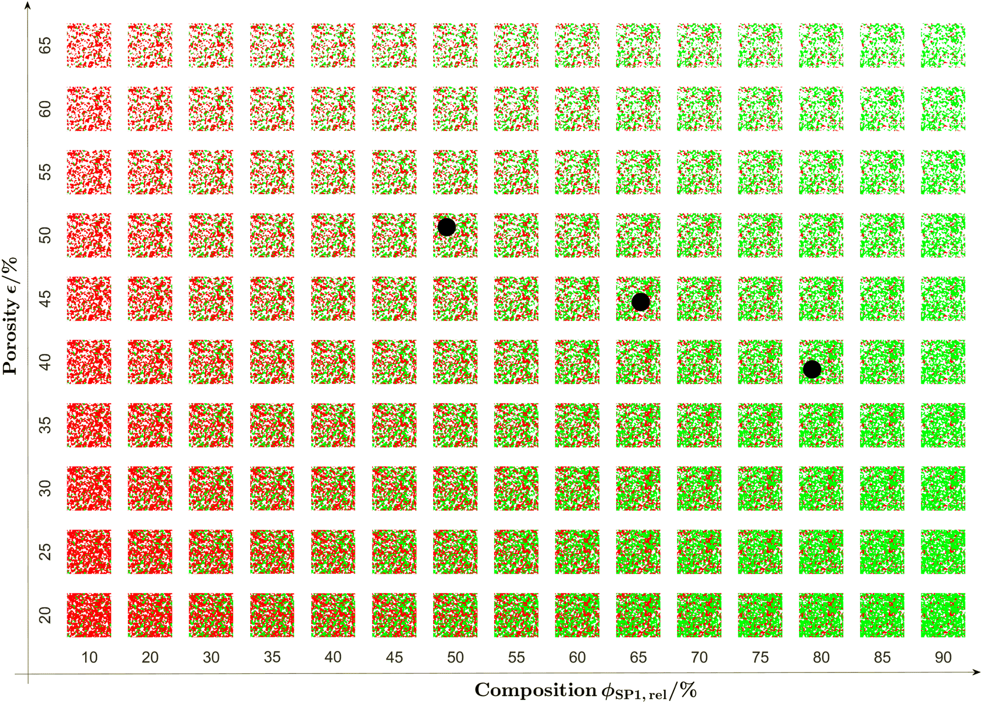 | ||
| Fig. 13 2D orthoslices of the virtual 3D microstructure variations porosity ranging from 20% to 65% and composition (i.e., relative solid phase volume fraction of CGO ϕSP1,rel) ranging from 10% to 90%. The virtual realizations are based on a pluri-Gaussian model (PGM), which is fitted to real structures for three digital microstructure twins. The three black dots correspond to composition and porosity of the real structures CGO40-LSTN60 (ϕSP1,rel = 48.7%, ε = 51.6%), CGO60-LSTN40 (ϕSP1,rel = 65.9%, ε = 44.4%) and CGO80-LSTN20 (ϕSP1,rel = 78.3%, ε = 38.7%) and to the corresponding digital twins, respectively. | ||
3.5 Microstructure properties for the virtual microstructure variation
In this section, a selection of microstructure properties of the virtual microstructure variation based on the digital microstructure twins are reported and will subsequently be referred as DT-dataset. This DT-dataset consists of 150 3D microstructure realizations, representing variations of the LSTN–CGO anode, as visualized in Fig. 13. Note that for two solid phases with the same characteristic sizes and neutral wetting behaviour, many microstructure properties show a symmetry with respect to the composition (i.e., the two solid phases are interchangeable). However, for a non-neutral wetting behaviour of the two solid phases (i.e., one solid phase has the tendency to wet the other solid phase), as it is the case for the DT-dataset, these symmetries are disturbed. This can be relevant for the microstructure optimization in the sense that optimal properties are achieved for different compositions and volume fractions. In order to clearly distinguish between general microstructure effects (e.g., directly resulting from composition and porosity) and effects related to the wetting behaviour and morphological details (e.g., bottlenecks) of the solid phases, a reference data set is reported in Section E of the ESI.† For this reference dataset, a virtual microstructure variation is performed with the PGM for different porosities and solid-phase compositions using neutral wetting conditions (i.e., using fixed threshold angles of α = 45° and β = γ = 0°) and without morphological manipulations (i.e., without step 4 of the workflow illustrated in Fig. 10). This dataset represents typical features of well-sintered SOC microstructures in an idealized form and shows a symmetric behaviour of many properties with respect to the composition. The abbreviation PGM-NW will be used to refer to this dataset.In Fig. 14 the contour plots of the volume specific interface areas and three-phase boundary length are reported as a function of the total solid volume fraction ϕtot (i.e., 100% – porosity, respectively) and the relative volume fraction of CGO ϕSP1,rel (i.e., composition, respectively). Thereby, the properties of all the microstructures from the DT-dataset (illustrated in Fig. 13) are determined. Additionally, the characteristics for 100% SP1 (CGO) and 100% SP2 (LSTN) are estimated using the properties of the merged total solid-phase (i.e., merged SP1 + SP2) from the nearest realized structures (i.e., compositions with SP1 either 10% or 90%, and with variable porosities).
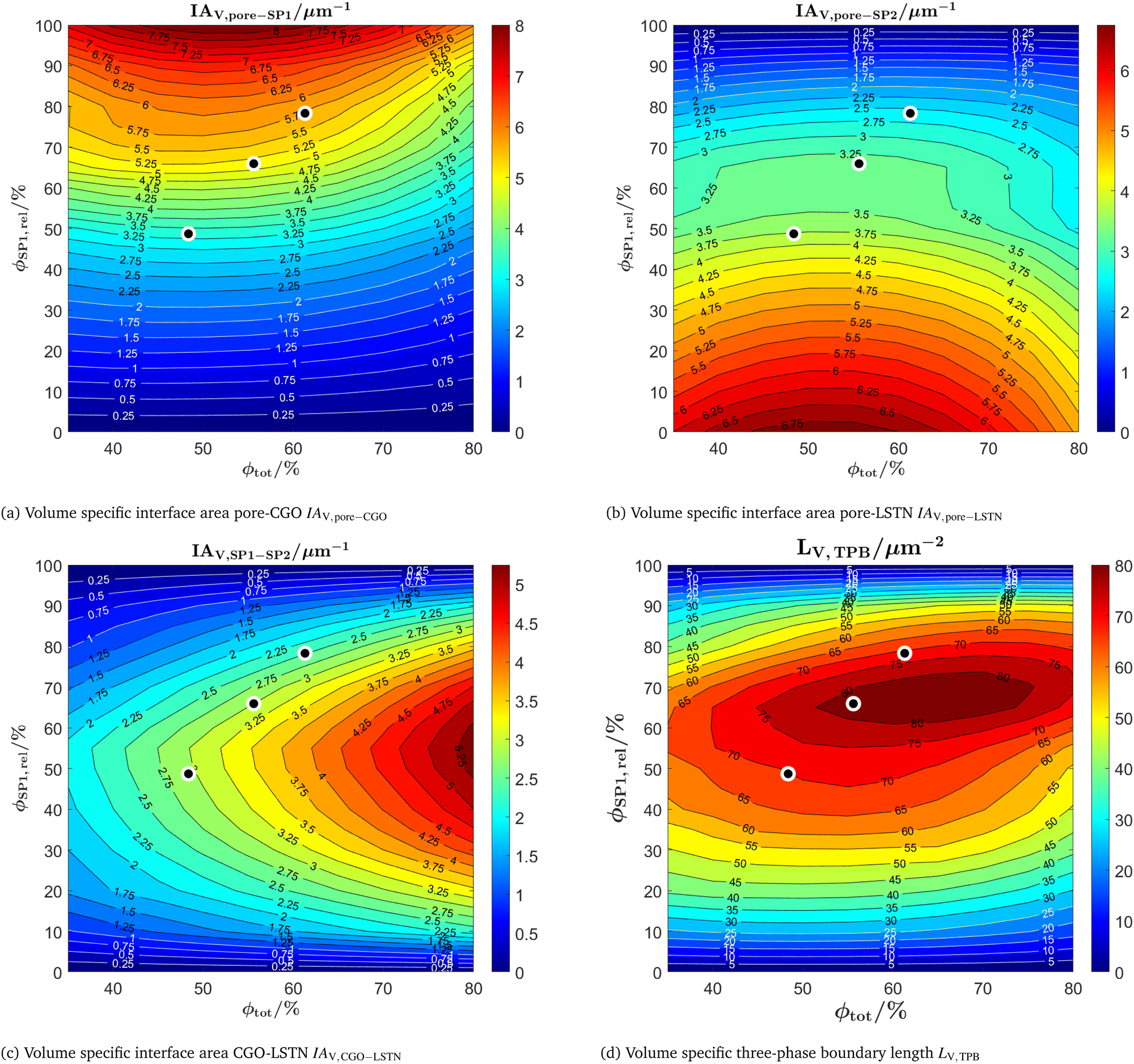 | ||
| Fig. 14 Contour plots of the volume specific interface areas (IAV) and the three-phase boundary length (LV,TPB) as a function of the total solid volume fraction ϕtot (i.e., 100% – porosity, respectively) and the relative volume fraction of CGO ϕSP1,rel (composition). The black dots represent the locations of the experimental data (real structures, tomography). Note: SP1 = CGO, SP2 = LSTN. (a) Volume specific interface area pore–CGO IAV,pore–CGO. (b) Volume specific interface area pore–LSTN IAV,pore–LSTN. (c) Volume specific interface area CGO-LSTN IAV,CGO–LSTN. (d) Volume specific three-phase boundary length LV,TPB. | ||
The pore–CGO interface area is considered as the main reaction site for fuel oxidation in LSTN–CGO anodes.1,10,11 Thus, the volume specific pore–CGO interface area (Fig. 14(a)) is very important for the reaction kinetics. It obviously correlates positively with the CGO-content (i.e. ϕSP1,rel). However, the positive correlation with the CGO-content is significantly stronger for the DT-dataset compared to the PGM-NW dataset. Furthermore, for variations of the porosity, it exhibits a maximum for a total solid volume fraction of about ϕtot = 50% (porosity of 50%, respectively). However, the pore–CGO interface area is more sensitive to the CGO-content than to the total solid volume fraction and porosity, respectively. Moreover, the data surface representing the variation of the pore–CGO interface is relatively flat around the maximum and therefore leaves some flexibility for trade-offs that might improve the overall anode performance. Such a trade-off could be, for example, an increase of the volume fraction of the LSTN-phase (SP2), in order to increase the effective electric conductivity. Or, alternatively, increasing the porosity in order to enhance the effective gas transport. Such trade-offs for eventual optimization of the performance will be considered in the subsequent discussion of microstructure variation and associated properties of the DT-dataset.
The volume specific pore–LSTN interface area (Fig. 14(b)) is another potential reaction site, although it is clearly less important for the reaction kinetics compared to the CGO-pore interface area.1,10,11 This difference can be attributed mainly to the high catalytic activity of CGO towards oxidation reactions. The LSTN-pore interface area correlates positively with the LSTN-content and it also shows a maximum for a total solid volume fraction of about ϕtot = 50% (i.e., porosity ε = 50%, respectively).
The volume specific CGO-LSTN interface area is a measure for the connection between the solid phases, which increases with the total solid volume fraction ϕtot. This property is slightly asymmetric with respect to the composition and it shows a maximum around ϕSP1,rel = 55%. This asymmetrical shift is not observed in the PGM-NW dataset in Fig. 12(c) of the ESI,† Section E. Moreover, the CGO-LSTN interface area is significantly higher for the DT-dataset compared to the PGM-NW dataset (Fig. 12(c) in the ESI,† Section E), which reflects a relatively good connection between LSTN and CGO. This is due to the non-neutral wetting that results from fitting of the construction parameters to the properties of real microstructures (i.e., matching of digital twins). This good connection with a high CGO–LSTN interface area also results in lower pore–CGO and pore–LSTN interface areas compared to the PGM-NW dataset for intermediate compositions around 50:50. Moreover, further asymmetrical behaviour is observed in the DT-dataset for intermediate compositions. For example, the volume specific pore–LSTN interface area (Fig. 14(b)) is slightly higher than the volume specific pore–CGO interface area (Fig. 14(a)). Also the correlation of the pore–LSTN interface with compositional variation (ϕSP1,rel) is less steep compared to the one for the pore–CGO interface. These asymmetrical phenomena can be explained by preferential wetting of LSTN on CGO. The same wetting behaviour is also present in the characteristics of the tomography data, but its effect on asymmetrical properties upon compositional variation only becomes apparent with the help of virtual microstructure variation and stochastic modeling.
The volume specific TPB-length (Fig. 14(d)) is a further potential reaction site in LSTN–CGO anodes, as e.g., discussed by Burnat et al.10 In the DT-dataset, the TPB-length reveals a maximum around a total volume fraction of ϕtot = 65% (i.e., porosity 35%) and a composition around ϕSP1,rel = 65% (relative fraction of CGO). Thus, there is a shift of the maximum towards higher CGO-contents compared to the PGM-NW dataset, which is symmetric with respect to the composition (see Fig. 12(d) in the ESI,† Section E). Again, this asymmetrical behaviour is attributed to the preferential wetting of LSTN on CGO. Moreover, the TPB-length values are significantly higher compared to the PGM-NW dataset, which is in accordance with the higher LSTN–CGO interface area for the DT-dataset.
Determination of the microstructure properties relevant for the gas and charge transport are computationally much more expensive compared to the volume specific interface areas and TPB-length. Furthermore, they show a much less complex behaviour as a function of composition and total solid volume fraction. Therefore, these properties are determined for a less dense matrix of ϕtot = [35,40,50,60,70,80]% and ϕrel,SP1 = [10:10:90]%. However, the full characterization of this reduced set of 54 microstructures is computationally still quite expensive. To obtain the results within a short time, Massive simultaneous cloud computing (MSCC) using GeoDict Cloud powered by Kaleidosim Technologies AG51 was used. The simultaneous (i.e., parallel) computing of multiple structures results in computation times that are almost independent from the number of structures to be calculated. For more detailed information about the MSCC concept we refer to the publications by Boiger et al.52–54
In Fig. 15 the relative conductivities are reported. The relative single-phase conductivity of CGO (i.e., SP1) is obviously maximal for a large total solid volume fraction ϕtot (i.e., low porosity) and a high CGO-content ϕSP1,rel (see Fig. 15(c)). Correspondingly, the relative single-phase conductivity of LSTN (i.e., SP2) is obviously maximal for a large total solid volume fraction ϕtot (i.e., low porosity) and a high LSTN-content ϕSP2,rel = 100% − ϕSP1,rel (see Fig. 15(d)). The relative single-phase conductivities are important for composites like Ni-YSZ, where the transport of electrons and ions happens in separate phases. In this context, they describe the microstructure effect on the transport relating the intrinsic with the effective conductivities (i.e., σeff,SP1 = σrel,SP1·σ0,SP1). However, in the LSTN–CGO composite both phases are MIECs, which results in significantly higher effective composite conductivities compared to the single-phase conductivities, as the transport of electrons and ions are no more restricted to one solid phase. Hence, the composite conductivities are the relevant properties in this case, while the single-phase conductivities can only be used as hypothetical references.
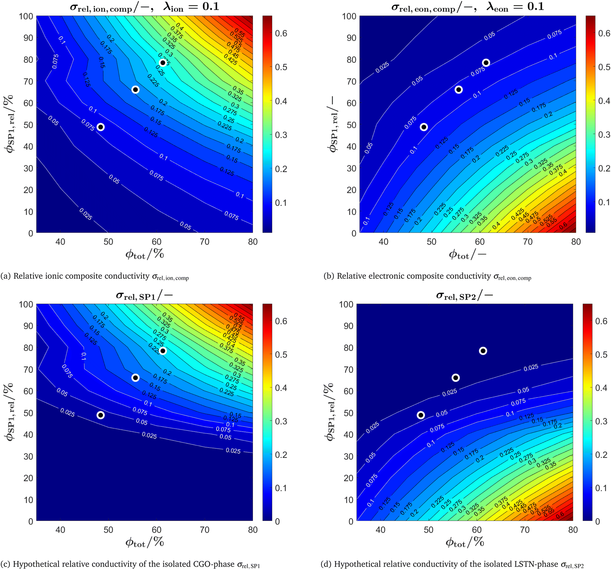 | ||
Fig. 15 Contour plots of (a) the relative ionic composite conductivity and (b) the relative electronic composite conductivity and the (hypothetical) single-phase conductivities of (c) the CGO-phase (SP1) and (d) the LSTN-phase (SP2) as a function of the total solid volume fraction ϕtot (i.e., 100% – porosity, respectively) and the relative volume fraction of CGO ϕSP1,rel (composition). The black dots represent the locations of the experimental data (real structures, tomography). Note: the composite conductivities are computed for fixed ratios of intrinsic conductivities σ0 in the two solid phases (i.e., ratio of the intrinsic ionic  and electronic and electronic  conductivities). conductivities). | ||
In Fig. 15(a), the relative ionic composite conductivities and in Fig. 15(b) the relative electronic composite conductivities are reported as a function of the total solid volume fraction ϕtot (i.e., 100% – porosity, respectively) and the relative volume fraction of CGO ϕSP1,rel (i.e., composition, respectively). In contrast to the single-phase conductivities, the microstructure effects for composite conductivity cannot be formulated independent from the intrinsic conductivities. Therefore, definitions for the relative ionic composite conductivities were introduced in a previous publication (Marmet et al.13) as a function of the ratio of intrinsic conductivities (i.e., ratio of the intrinsic electronic  and ionic
  conductivities of the two solid phases). According to the estimations reported in Table 4 for the LSTN–CGO composite, the intrinsic ionic conductivity of CGO is about a factor of 10 higher compared to LSTN, resulting in an intrinsic conductivity ratio of λion = 0.1. In contrast, the intrinsic electronic conductivity of LSTN is about a factor of 10 higher compared to CGO, resulting in an intrinsic conductivity ratio of λeon = 0.1. The corresponding relative ionic and electronic composite conductivities are reported in Fig. 15(a) and (b), respectively. The relative ionic composite conductivity has its maximum at the same corner as the single-phase conductivity of CGO (SP1), as the influence of the LSTN-phase vanish for high CGO-contents. However, the reduction of the ionic composite conductivity with decreasing CGO-content ϕSP1,rel in (a) is much less steep compared to the single-phase conductivity in (c), because LSTN (SP2) contributes as well to the composite conductivity (although it has a lower intrinsic conductivity). The enhancement of the relative composite conductivity compared to the single-phase conductivity is especially large for low volume fractions of CGO (SP1), where bottlenecks and islands in CGO can be bridged by LSTN (SP2). This effect results in a much larger enhancement of the ionic composite conductivity with respect to the single-phase conductivity of CGO (SP1) than only the single-phase contribution of LSTN (SP2) with its relatively low ionic conductivity. For the relative electronic composite conductivity (Fig. 15(b)), the same behaviour can be observed vice versa. Compared to the single-phase and composite conductivity of the PGM-NW dataset (see Fig. 13 in the ESI,† Section E), the overall trends are very similar. The DT-dataset shows a more complex and less smooth behaviour because of the inter- and extrapolation of the construction parameters between and beyond the digital twins. A detailed discussion of the composite conductivity and its implications on the microstructure design is beyond the scope of the present paper, but these issues will be discussed in great detail in a separate publication that is focusing specifically on composite conductivity (see also PhD thesis of Ph. Marmet13).
The contour plots of the microstructure properties relevant for the gas transport according to the dusty gas model (described in Marmet et al.13,15) are shown in Fig. 16. The relative diffusivities for bulk (Fig. 16(a)) and Knudsen (Fig. 16(b)) diffusion decrease with decreasing porosity (i.e., increasing total solid volume fraction ϕtot), while the values are almost constant with respect to the composition ϕSP1,rel. The Knudsen characteristic length (Fig. 16(c)) decreases with decreasing porosity. The weak dependency on the composition ϕSP1,rel is due to the change of the morphology of the pore-phase along the compositional variation. A similar behaviour is observed for the gas permeability (Fig. 16(d)), with the difference that the dependency on the porosity (and associated pore size) is more pronounced, which is a direct result of the quadratic relation of the permeability κ with the hydraulic radius rhc (i.e., κ ∝ rhc2, see Marmet et al.13). In general, the same trends as reported for PGM-NW dataset (Fig. 14 in Section E of the ESI†) can be observed. However, there is also a slight distortion of the regular pattern for all four parameters, which results from the fitting of the DT-dataset to the real microstructure. Thereby, some slightly unusual gas transport properties for the intermediate sample LSTN40-CGO60 causes some disturbances of the regular pattern that is otherwise present in the NW-dataset. As the fit of the DT-dataset is based on a small number of real samples, the influence of fabrication variations can neither be determined nor clearly distinguished from a possible systematic dependency on the composition. Note that the gas transport properties are almost independent for compositions with CGO-contents lower than 50% and higher than 80%, simply because fixed threshold angles and voxel sizes of the nearest digital microstructure twin were used for extrapolation and realization of the DT-dataset.
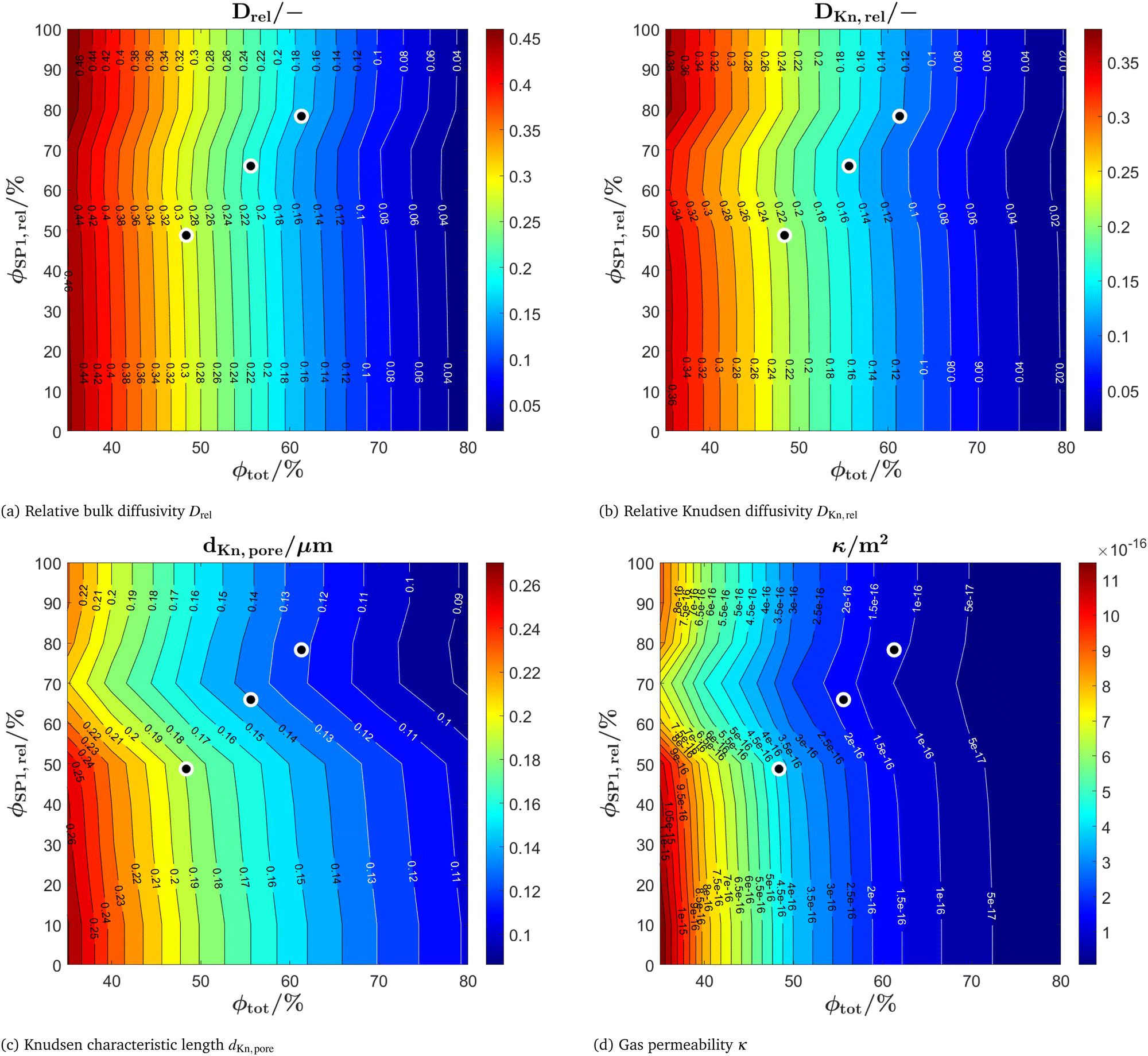 | ||
| Fig. 16 Contour plots of the effective transport properties of the pore-phase (for the parametrization of the dusty-gas model) as a function of the total solid volume fraction ϕtot (i.e., 100% – porosity, respectively) and the relative volume fraction of CGO ϕSP1,rel (composition): (a) relative bulk diffusivity, (b) relative Knudsen diffusivity, (c) Knudsen characteristic length and (d) gas permeability. The black dots represent the locations of the experimental data (real structures, tomography). | ||
The microstructure characteristics (e.g., surface area, TPB-length) and effective transport properties (e.g., effective gas diffusivity, effective electric and ionic conductivity) can be used as input for physical electrode models. In this way, the corresponding electrode performance for the entire set of microstructures can be predicted in a reliable way. Since the formulation and implementation of such electrode models is a very demanding task, this will be an issue for a separate paper, and it is beyond the scope of this publication. However, as a first estimate of the electrode performances associated with the simulated microstructure variations, some figures of merit that can be estimated with a simplified approach shall be reported here. According to the analytical model presented by Adler et al.55 derived for an oxygen electrode with a single MIEC phase (e.g., LSCF), the inverse ASR of the cell scales with the square root of the effective ionic conductivity and the active surface. Note that this estimate is formulated for the case that the transport of gas species and the transport of electrons is not limiting. Especially the first assumptions is violated for the current dataset, which contains microstructures with very low porosity. Moreover, the composite electrode with two MIEC phases shows additional complexity like different possible reaction sites (i.e., oxidation reactions taking place on the surfaces of CGO and LSTN, and in addition also at the TPBs). Nevertheless, the estimate of the ASR based on Adlers model is still partially valid and can be considered as a reasonable first guess (for more information on the limitation of this approach see also discussion section below). For the LSTN–CGO electrode this approach yields:
 | (10) |
 | ||
| Fig. 17 Figures of merit for the electrode performance assuming that the transport of gas species and the transport of electrons is not limiting. The corresponding contour plots are shown as a function of the total solid volume fraction ϕtot (i.e., 100% – porosity, respectively) and the relative volume fraction of CGO ϕSP1,rel (composition) for (a) a surface active electrode and (b) a classical TPB active electrode (e.g., Ni-YSZ). Note that the data is normalized to values between 0–1. | ||
It can be assumed that our simulated microstructures are representing single conducting phases (instead of MIECs). The set of microstructures would then represent for example Ni-YSZ electrodes, which are actually the most frequently used SOFC anodes. For the case of a TPB-active electrode like Ni-YSZ, where the transport of oxygen ions and electrons occur in separate phases, the inverse ASR scales with the contiguous portion of the volume specific TPB-length. Hence, the corresponding figure of merit for the performance of this important reference case is reported here, even if it is not directly applicable for the used LSTN–CGO dataset:
 | (11) |
4 Discussion
This discussion section is structured in two parts. First, the results of the virtual microstructure variations are discussed regarding an optimization of SOC anodes. Second, the presented stochastic microstructure modeling approach is discussed from a methodological point of view.4.1 Digital twin (DT) dataset: towards optimization of anode microstructure
A stochastic PGM model was fitted against real experimental microstructure data from tomography. The parameter variation with PGM is then used to realize 3D structures, which cover a wide range of different compositions and total solid volume fractions (or porosities, respectively) and which have realistic properties. This digital twin DT-dataset is the basis for optimization of microstructure properties and electrode performance. In this paper, we do not provide a detailed electrode model, but instead the electrode performances of the different microstructures are estimated with a simplified analytical model for MIEC electrodes from Adler et al.55 In general, the reaction kinetics and fuel oxidation activities in SOC electrodes are related to the interface areas and/or to the TPB-length, depending on the material system. It has been shown by several authors1,10,11 that for perovskite-CGO anodes, the pore–CGO interface area is the most relevant microstructure feature for the reaction kinetics. The corresponding figure of merit ASRsurface−1, which provides a simple estimation of the electrode performance based on Adlers model (see eqn (10)), is reported in Fig. 17(a). Thereby, the pore–CGO interface area is considered as the only active reaction site and the ionic composite conductivity is inserted as the relevant property for transport limitation. Both properties positively correlate with the CGO-content (see Fig. 14(a) and 15(a), respectively). Consequently, ASRsurface−1 in Fig. 17(a) is maximal for a pure CGO electrode. Moreover, high total solid volume fractions are favourable and ASRsurface−1 is maximal around ϕtot = 80% and porosity 20%, respectively (note that the maximum around 80% is even clearer for the PGM-NW dataset, reported in Fig. 15(a) of ESI,† Section E). However, it must be emphasized that the overpotential due to gas transport is neglected with Adlers approach, which is especially inappropriate for microstructures with low porosities (i.e., high ϕtot). Nevertheless, the total solid volume fraction of an optimized LSTN–CGO anode might be considerably higher than ϕtot = 50% (where the maximal pore–CGO interface area is expected according to Fig. 14(a)) because of the facilitated charge transport that can be achieved with higher ϕtot. A discussion of additional figures of merit that take into account additional reaction sites for fuel oxidation in LSTN–CGO electrodes can be found in Section G of the ESI.†The microstructure data in combination with a simplified analytical electrode model can also be used to explore microstructure effects in conventinal electrodes, which typically consist of ‘non-MIEC’ materials. As a reference, the figure of merit ASRTPB,cont.−1 reported in Fig. 17(b) (according to eqn (11)) relevant for TPB-active electrodes like Ni-YSZ shall be discussed. It must be emphasized that this figure of merit using the ionic single-phase conductivity of SP1 (i.e., YSZ alias CGO) and the contiguous TPB-length does not represent a realistic measure for the performance of an LSTN–CGO electrode. Nevertheless, it is helpful to illustrate the basic differences between composite MIEC electrodes (e.g., LSTN–CGO) and conventional electrodes with single-phase conductors (e.g., Ni-YSZ). In the following discussion, the nomenclature SP1TPB will be used to refer to an ion-conducting phase (e.g., YSZ) without MIEC-properties, but using the microstructure geometry of CGO (SP1). The corresponding figure of merit ASRTPB,cont.−1 is plotted in Fig. 17(b). In contrast to a surface active electrode (see Fig. 17(a)), ASRTPB,cont.−1 is zero for a SP1TPB-content of 100%, because the TPB-length is going to zero, when SP2 is removed from the microstructure. The maximal value ASRTPB,cont.−1 is located at an electrode composition with slightly higher volume fractions for YSZ (SP1TPB-content of 75%) than the maximal value of the contiguous TPB-length itself (SP1TPB-content of 70%, see Fig. 15(c) of the ESI,† Section G). This shift of maximum for ASRTPB,cont.−1 can be explained because of the higher ionic conductivity associated with higher SP1TPB-contents (i.e., the ion conducting YSZ-phase). Moreover, the electrode performance ASRTPB,cont.−1 practically vanishes for SP1TPB-contents below 20%, because the solid volume fraction of the ion-conducting phase SP1TPB drops below the percolation threshold (see Fig. 15(c)). The performance of the same microstructures, but with MIEC materials properties, is significantly different (see ASRsurface−1 in Fig. 17(a)). For MIEC composite electrodes, the decrease of the relative ionic composite conductivity (Fig. 15(a)) with decreasing CGO-content is much less steep than for the single-phase conductivity of SP1TPB (Fig. 15(c)). This behaviour can be explained by the fact that the LSTN-phase (SP2) owns MIEC properties and is thus able to bridge bottlenecks and islands of the CGO-phase (SP1), which considerably enhances the transport of ions in such composite electrodes (i.e., the relative ionic composite conductivity). This makes a big difference for compositions where the volume fraction of one phase drops below the percolation threshold. Hence, for MIEC electrodes with very asymmetric compositions (i.e., with low CGO-content and high LSTN-content), the ionic composite conductivity is typically much higher than the single-phase contribution of LSTN. It is important to note, that in conventional electrodes (e.g., Ni-YSZ), the single-phase conductivity is the relevant property. As a consequence, in conventional anodes, the range of compositions that can reasonably be included into a microstructure optimization space is strongly limited, whereas in MIEC based electrodes, the positive effects associated with composite conductivity open a much larger design space. The effects of the composite conductivity and its implications on the microstructure optimization will be discussed in more detail in a separate publication (see also chapter 6 of the PhD thesis by Ph. Marmet16).
In summary, the following effects can be identified as the main microstructure limitations of titanate-CGO anodes:
• In LSTN–CGO anodes, the electrochemical fuel oxidation reaction mainly takes place on the CGO surface, which is a specific feature of MIEC materials with high catalytic activity. A low pore–CGO interface area thus represents a limiting factor for fuel oxidation. This limitation occurs at low CGO-contents, as shown in Fig. 14(a). This limiting effect can become even more pronounced when low CGO-contents are combined with either very high or very low porosities.
• In conventional anodes (e.g., Ni-YSZ), the TPB-length is of major importance for fuel oxidation (instead of the CGO surface), and thus the composition needs to be chosen accordingly. For the DT-dataset, a maximum TPB-length is observed at a composition of SP1:SP2 = 65:35 and porosity of 35% (see Fig. 14(d)). The asymmetry of the TPB-plots (i.e., not SP1:SP2 = 50:50) can be attributed to the non-neutral wetting behaviour of the solid phases. Nevertheless, it must be emphasized that in LSTN–CGO anodes the TPB is assumed to be of lesser importance for the fuel oxidation reaction, compared to the pore–CGO interface area.
• Charge transport is mainly limited by the volume fraction of the phase with higher intrinsic conductivity, which is CGO for ionic transport and LSTN for electronic transport. The phase volume fraction not only depends on composition, but also on porosity. Hence, a high porosity (low total solid volume fraction, respectively) puts a major constraint on both charge transports, as illustrated in Fig. 15(a) and (b) for the ionic and electronic composite conduction. In order to achieve a high ionic composite conductivity, it is thus necessary to design the microstructure towards a CGO-rich composition with low porosity. In a similar way, a high electronic composite conductivity is achieved with an LSTN-rich composition and low porosity.
• In contrast to charge transport, the gas transport is mainly limited by low porosity (high total solid volume fraction, respectively), which is illustrated in Fig. 16(a) for gas diffusivity. In fine porous anodes, the gas diffusion is additionally hindered by the Knudsen effect (i.e., by collision of gas particles at the pore wall). A decrease in porosity typically also coincides with a reduction of the pore size (i.e., characteristic length, respectively). Consequently, there is an additional negative correlation on the gas transport due to the Knudsen effect with decreasing porosity.
A more detailed discussion of these microstructure effects can be found in the PhD thesis of Ph. Marmet.16
For a real microstructure optimization of composite anodes, there are many additional effects that need to be considered. Thereby, it is necessary taking into account all specific properties associated with the cell architecture and involved materials. For example, it was shown that the addition of perovskite typically contributes to a higher mechanical stability of CGO based anodes (see e.g., Sciazko et al.1). A very low LSTN-content may thus strongly limit the mechanical stability of LSTN–CGO anodes. Another issue, which heavily depends on the cell architecture, is the in-plane conduction associated with the current collection. In some cell designs, the geometry of current collectors and electrode layers induce a relatively high contribution of in-plane currents. In such cells, a high electronic composite conduction should receive a high priority in the framework of the overall microstructure optimization. In contrast, for cell designs where the in-plane current collection is reliably fulfilled by a separate layer, the electronic conductivity is typically not limiting. In general, the optimum of these various limitations and associated trade-offs that must be encountered upon microstructure optimization depends on numerous aspects, such as the cell architecture (e.g., electrode layer thickness, concept and design for current collection), the catalytic properties of the electrode (e.g., use of an additional catalyst like Ni or noble metals) and the operating conditions (e.g., temperature, fuel composition, fuel utilization). The most reliable way to solve such an optimization problem is to use multiphysics electrode models that are capable of predicting the performance as a function of electrode microstructure and associated material properties, respectively. This approach was described in literature by various authors, – for example for pure CGO electrodes by Marmet et al.,15 for Ni-YSZ electrodes by Dierickx et al.56 and by Monaco et al.,57 for a nickel-infiltrated CGO electrode by Kishimoto et al.58 or for LSCT-CGO electrodes by Marmet.16 The combination of such physical electrode models with input from stochastic microstructure modeling, opens new possibilities for data-driven microstructure optimization. The corresponding concepts of Digital Materials Design (DMD) is illustrated in Fig. 1.
4.2 Realistic microstructure variations with a pluri Gaussian model (PGM): method and workflow
Stochastic microstructure modeling based on Gaussian random fields (i.e., PGM), as it is described in the present paper, represents an important method in the modular framework for digital materials and microstructure design. In this context, we discuss the workflow for the construction of the digital microstructure twins including the systematic virtual microstructure variation. The main goal of such a workflow is to provide a basic understanding of the different microstructure parameters and to establish a basis for the microstructure optimization, i.e., providing design guidelines for improved electrodes in a feedback loop to the cell fabrication. The accuracy of the various property predictions needs to be high enough to capture the major trends associated with microstructure variation. Hence, for optimization purposes, the absolute accuracy of a single data point (i.e., prediction accuracy of a property for a given electrode composition) is less important than capturing the overall trends correctly. The performance and the microstructure properties of a new, optimized cell that was fabricated according to the design guidelines from a first loop in the optimization study can then be used as an additional input for the microstructure variation and the calibration of the electrode model (as illustrated in Fig. 1) in a second iteration loop of the DMD process. The aim is to need as few experimental points and iterations as possible to achieve reliable model predictions and satisfying guidelines for an optimized electrode design. Therefore, the quality of all the steps in the workflow needs to be sufficient. The cell fabrication especially needs to be reproducible. For a reliable and reproducible microstructure characterization, a standardized workflow should be used for the image acquisition, segmentation and the determination of the microstructure properties (as e.g., presented in Marmet et al.13). From a scientific point of view, ideally there should be a large number of tomography data available, representing parameter variations in the fabrication process and their impact on microstructure properties. However, 3D imaging by tomography methods is expensive and time consuming, which often results in more pragmatic strategies with only a few 3D tomography data, as it is the case for the current study. Nevertheless, the use of only three anchor points in the current study has the drawback that it is not possible to distinguish properly between real microstructure trends and random variations due to the fabrication and characterization of the cells. Moreover, in the experimental data of the present study, there is no controlled variation of the porosity represented by the real microstructures from tomography. In future studies, the porosity might be varied by changing the sintering conditions or by using pore-formers. These measures might cause additional changes to the morphology of the microstructure, which are not included in the current stochastic microstructure model and which are therefore also not captured by the property predictions for variable porosities in the DT-dataset. In summary, the presented study captures the main trends and points the right direction for efficient microstructure optimization. However, additional DMD-loops are needed for this optimization process.An important element of this DMD process is the availability of a virtual structure generator, which is able to construct realistic structures of a specific type. In the literature,28–30 it is well accepted that the pluri-Gaussian method (PGM) is a well suited approach to model SOC microstructures. While the construction of pluri-Gaussian random fields are available in many software packages like R (Valakas et al.59) or Matlab (Moussaoui et al.28), a continuous workflow as presented in this publication based on the GeoDict platform including a standardized SOC microstructure characterization (reported in Marmet et al.13) and the stochastic microstructure modeling (presented in this paper) has to the best of our knowledge not been reported before.
The microstructure properties obtained according to this workflow show a considerably different behaviour as a function of composition and porosity compared to the basic data for neutral wetting behaviour. This illustrates the necessity of (a) the fitting-procedure with realistic data from tomography and (b) an inter/extrapolation procedure of the construction parameters if one wants to achieve realistic microstructure variation for the subsequent optimization. The accuracy of the current approach for stochastic microstructure modeling could be improved by additional variation of construction parameters for the PGM. The variation could be extended to different characteristic sized of the two GRFs (i.e., different particle sizes of the two solid phases). Moreover, more complex models for the correlation functions of the GRFs with additional parameters could be used, as e.g., suggested by Neumann et al.30 Furthermore, the fitting of the model parameters could be supported by machine learning algorithms.
In this study, virtual microstructures for the whole relevant range of compositions and porosities were generated and characterized. This systematic variation facilitates an intuitive understanding of the impact of a parameter variation to the resulting microstructure properties. Moreover, it allows for a decoupling of the microstructure analysis and other aspects influencing the cell performance. For example, different cell designs might result in different requirements for the microstructure. However, if a larger number of parameters like e.g., powder size, sintering temperature, pore-former, material types and compositions etc., shall be studied simultaneously, the study of the whole relevant parameter space would result in an enormous number of data-points. For such studies, the use of optimization algorithms selecting the microstructures to be studied would be favourable.
5 Conclusion
In this contribution, a workflow for the virtual but realistic microstructure variation based on real tomography data is presented, which is a key element of our Digital Materials Design (DMD) approach. A set of three real 3D microstructures captured from LSTN–CGO anodes using FIB-tomography with different compositions and porosities is used as a basis. Digital microstructure twins are constructed for each of the three real microstructures. The virtual structure generation is based on the pluri-Gaussian method (PGM), using a Gaussian model for the correlation function of the Gaussian random fields for the two solid phases and five parameters for the threshold operations; two for the phase volume fractions and three to control the morphological details as e.g., the wetting of the phases. In order to match the microstructure properties of the virtual structure (i.e., digital twin) with those of the real structure, the construction parameters for the PGM-model are determined by interpolation of a database of virtual structures. Moreover, the relative conductivities of the phases are optimized by finetuning of specific microstructural features (e.g., connectivity of bulges) using morphological operations. The three digital microstructure twins are then used as anchor points for a parameter variation for composition and porosity, using linear interpolation of the construction parameters for the virtual structure generation with the PGM-model. For all the virtual structures of the parameter study, the corresponding microstructure properties are determined using a standardized and automated microstructure characterization tool, which is described in Marmet et al.13The presented workflow for stochastic microstructure modeling can be performed with a reasonable effort and the achievable level of accuracy is well aligned with other uncertainties of the study. However, the needed effort can be significantly reduced by foregoing the step for the morphological optimization of the relative conductivities. This can be e.g., sufficient for studies where a specific microstructure variation is based on a series of 2D images only. Thereby, an accurate characterization of the relative conductivities is not possible for the experimentally realized samples, whereas the interface properties can be reasonably described. More generally, the variation of microstructure property data for porosity and composition with neutral wetting behaviour as presented in Section E of the ESI,† can even be considered as a first guess of general microstructure-property relationship for SOC electrodes by only scaling the presented results to a specific characteristic structure size (i.e., particle size, respectively). On the contrary, for cases with a large experimental bases of real 3D structures representing a specific variation, additional efforts with respect to the presented approach might be justified, by e.g., using systematic variations of different characteristic structure sizes for the two solid phases or the parametrization of more complex functions describing the GRFs. Thus, the presented approach can be adapted to different constraints of specific studies concerning available resources and needed accuracy.
The main goal of such a workflow is to provide a basic understanding of the different microstructure effects associated with the employed parameter variations and thereby also to provide a basis for the controlled microstructure optimization, i.e., providing design guidelines for improved electrode performance in a feedback loop to the cell fabrication. Some qualitative suggestions about the trade-off between the different microstructure effects determining the gas transport, charge transport and reaction kinetics are already possible by studying the behaviour of the properties as a function of porosity and composition. For example, the volume specific pore–CGO interface area, which is the most important microstructure property for the reaction kinetics in LSTN–CGO anodes, is maximal around a total solid volume fraction of ϕtot = 50% and, simultaneously, high CGO-contents. On the other hand, the relative ionic composite conductivity is rather low for ϕtot = 50% and increases strongly for increasing total solid volume fraction ϕtot > 50%. As the decrease of the pore–CGO interface area with increasing total solid volume fraction ϕtot is moderate, the optimal ϕtot for the best electrode performance can be expected to be considerably higher than ϕtot = 50%. Fore very high ϕtot (i.e., very low porosities), the gas transport might become the limiting factor, especially in combination with small pore-sizes associated with a higher gas transport resistance due to Knudsen diffusion effects. Such considerations are helpful for a rough and qualitative optimization. However, for a more quantitative optimization, the available microstructure properties can be used to feed a multiphysics electrode model, that is capable to predict the performance for each specific electrode design. In this way, performance variations for the entire design space can be estimated, and finally the best performing microstructure(s) can be identified. The presented approach is a key element for the DMD process, presented in Section 1. However, this is expected to be an iterative process. For example, the presented virtual microstructure variation is expected to provide the right tendencies towards the optimal microstructure. Interesting virtual microstructures, which are far away from the anchor points represented by the digital microstructure twins are not expected to precisely predict the true properties and, thus, they need to be realized experimentally. These additional real data-points can then be used for an improved virtual structure variation for a next DMD optimization loop, if needed.
In summary, Digital Materials Design (DMD) offers new possibilities for data-driven materials and microstructure optimization. Despite the progress in imaging technology, 3D-imaging is still expensive in terms of time and costs and 3D-structures from tomography still represent a bottleneck for the application of DMD. The presented microstructure modeling approach is able to extend the availability of realistic microstructures dramatically. The availability of appropriate tools to efficiently construct realistic virtual microstructures is a crucial point, which is addressed by including the PGM-app in the GeoDict 2023 release as a so-called GeoApp. For the microstructure properties, a standardized and automated microstructure characterization tool was presented in Marmet et al.,13 which facilitates the comparison of microstructure property data from different sources. Last but not least, it must be emphasized that even though the examples used to document this DMD workflow are dedicated to solid oxide cells, this workflow is adaptable to other energy materials applications like proton-exchange membrane fuel cells, Li-ion batteries and flow batteries.
Conflicts of interest
There are no conflicts to declare.Acknowledgements
This publication is based mainly on two research projects that received financial support from the Swiss Federal Office of Energy (SFOE, grant SI/501792-01 – 8100076) and from Eurostars (grant E!115455), which are gratefully acknowledged.References
- A. Sciazko, Y. Komatsu, R. Yokoi, T. Shimura and N. Shikazono, J. Eur. Ceram. Soc., 2022, 42, 1556–1567 CrossRef CAS.
- M. S. Khan, S. B. Lee, R. H. Song, J. W. Lee, T. H. Lim and S. J. Park, Ceram. Int., 2016, 42, 35–48 CrossRef CAS.
- L. Holzer, B. Iwanschitz, T. Hocker, B. Münch, M. Prestat, D. Wiedenmann, U. Vogt, P. Holtappels, J. Sfeir, A. Mai and T. Graule, J. Power Sources, 2011, 196, 1279–1294 CrossRef CAS.
- H. He and J. M. Hill, Appl. Catal., A, 2007, 317, 284–292 CrossRef CAS.
- G. Brus, R. Nowak, J. S. Szmyd, Y. Komatsu and S. Kimijima, J. Theor. Appl. Mech., 2015, 53, 273–284 CrossRef.
- F. Yu, J. Xiao, Y. Zhang, W. Cai, Y. Xie, N. Yang, J. Liu and M. Liu, Appl. Energy, 2019, 256, 113910 CrossRef CAS.
- Y. Matsuzaki and I. Yasuda, Solid State Ionics, 2000, 132, 261–269 CrossRef CAS.
- D. Fouquet, A. C. Müller, A. Weber and E. Ivers-Tiffée, Ionics, 2003, 9, 103–108 CrossRef CAS.
- L. Shu, J. Sunarso, S. S. Hashim, J. Mao, W. Zhou and F. Liang, Int. J. Hydrogen Energy, 2019, 44, 31275–31304 CrossRef CAS.
- D. Burnat, G. Nasdaurk, L. Holzer, M. Kopecki and A. Heel, J. Power Sources, 2018, 385, 62–75 CrossRef CAS.
- R. Price, M. Cassidy, J. G. Grolig, A. Mai and J. T. S. Irvine, J. Electrochem. Soc., 2019, 166, F343–F349 CrossRef CAS.
- D. Burnat, R. Kontic, L. Holzer, P. Steiger, D. Ferri and A. Heel, J. Mater. Chem. A, 2016, 4, 11939–11948 RSC.
- P. Marmet, L. Holzer, T. Hocker, G. K. Boiger, H. Bausinger, A. Mai, M. Fingerle, S. Reeb, D. Michel and J. M. Brader, Energy Adv., 2023, 2, 980–1013 RSC.
- L. Holzer, P. Marmet, M. Fingerle, A. Wiegmann, M. Neumann and V. Schmidt, Tortuosity and microstructure effects in porous media: classical theories, empirical data and modern methods, Springer, Cham, ISBN: 978-3-031-30477-4, 1st edn, 2023 Search PubMed.
- P. Marmet, L. Holzer, J. G. Grolig, H. Bausinger, A. Mai, J. M. Brader and T. Hocker, Phys. Chem. Chem. Phys., 2021, 23, 23042–23074 RSC.
- P. Marmet, PhD thesis, Digital Materials Design of Solid Oxide Fuel Cell Anodes, University of Fribourg, Switzerland, 2023 DOI:10.21256/zhaw-28430.
- E. M. Ryan and P. P. Mukherjee, Prog. Energy Combust. Sci., 2019, 71, 118–142 CrossRef.
- L. Holzer, P. Marmet, M. Fingerle, A. Wiegmann, M. Neumann and V. Schmidt, Tortuosity and microstructure effects in porous media: classical theories, empirical data and modern methods, Springer, Cham, 1st edn, 2023 Search PubMed.
- S. N. Chiu, D. Stoyan, W. S. Kendall and J. Mecke, Stochastic Geometry and Its Applications: Third Edition, Wiley, Chichester, UK, 2013 Search PubMed.
- G. Matheron, Random sets and integral geometry, Wiley, New York, 1975 Search PubMed.
- D. Jeulin, Morphological Models of Random Structures, Springer, Cham, 2021 Search PubMed.
- C. Lantuéjoul, Geostatistical simulation: Models and algorithms, Springer Berlin Heidelberg, Berlin, 2002 Search PubMed.
- V. Schmidt, Stochastic Geometry, Spatial Statistics and Random Fields, Cham, 2014 Search PubMed.
- S. Bargmann, B. Klusemann, J. Markmann, J. E. Schnabel, K. Schneider, C. Soyarslan and J. Wilmers, Prog. Mater. Sci., 2018, 96, 322–384 CrossRef.
- B. Sheikh and A. Pak, Phys. Rev. E: Stat., Nonlinear, Soft Matter Phys., 2015, 91, 1–14 CrossRef PubMed.
- Y. Nishida and S. Itoh, Electrochim. Acta, 2011, 56, 2792–2800 CrossRef CAS.
- B. Shri Prakash, S. Senthil Kumar and S. T. Aruna, Renewable Sustainable Energy Rev., 2014, 36, 149–179 CrossRef CAS.
- H. Moussaoui, J. Laurencin, Y. Gavet, G. Delette, M. Hubert, P. Cloetens, T. Le Bihan and J. Debayle, Comput. Mater. Sci., 2018, 143, 262–276 CrossRef CAS.
- B. Abdallah, F. Willot and D. Jeulin, J. Microscopy, 2016, 263, 51–63 CrossRef CAS PubMed.
- M. Neumann, B. Abdallah, L. Holzer, F. Willot and V. Schmidt, Tran. Porous Media, 2019, 128, 179–200 CrossRef.
- Y. Suzue, N. Shikazono and N. Kasagi, J. Power Sources, 2008, 184, 52–59 CrossRef CAS.
- M. Neumann, J. Stanek, O. M. Pecho, L. Holzer, V. Beneš and V. Schmidt, Comput. Mater. Sci., 2016, 118, 353–364 CrossRef CAS.
- A. Gayon-Lombardo, L. Mosser, N. P. Brandon and S. J. Cooper, npj Comput. Mater., 2020, 6, 1–11 CrossRef.
- T. Hsu, W. K. Epting, H. Kim, H. W. Abernathy, G. A. Hackett, A. D. Rollett, P. A. Salvador and E. A. Holm, JOM, 2021, 73, 90–102 CrossRef.
- A. Sciazko, Y. Komatsu and N. Shikazono, ECS Trans., 2021, 103, 1363–1373 CrossRef CAS.
- M. Prioux, E. Da Rosa Silva, M. Hubert, J. Vulliet and J. Laurencin, 15th European SOFC & SOE Forum, EFCF, 2022, p. B1602 Search PubMed.
- A. Hasanabadi, M. Baniassadi, K. Abrinia, M. Safdari and H. Garmestani, Comput. Mater. Sci., 2016, 123, 268–276 CrossRef CAS.
- S. Buchaniec, A. Sciazko, M. Mozdzierz and G. Brus, IEEE Access, 2019, 7, 34361–34372 Search PubMed.
- M. Riazat, M. Tafazoli, M. Baniassadi, M. Safdari, G. Faraji and H. Garmestani, Comput. Mater. Sci., 2017, 127, 1–7 CrossRef CAS.
- M. Baniassadi, H. Garmestani, D. S. Li, S. Ahzi, M. Khaleel and X. Sun, Acta Mater., 2011, 59, 30–43 CrossRef CAS.
- M. M. Sebdani, M. Baniassadi, J. Jamali, M. Ahadiparast, K. Abrinia and M. Safdari, Int. J. Hydrogen Energy, 2015, 40, 15585–15596 CrossRef CAS.
- M. Tafazoli, M. Shakeri, M. Baniassadi and A. Babaei, Int. J. Energy Res., 2017, 41, 2318–2331 CrossRef CAS.
- M. Neumann, M. Osenberg, A. Hilger, D. Franzen, T. Turek, I. Manke and V. Schmidt, Comput. Mater. Sci., 2019, 156, 325–331 CrossRef CAS.
- P. Marmet, L. Holzer, T. Hocker, V. Muser, G. K. Boiger, M. Fingerle, S. Reeb, D. Michel and J. M. Brader, Python app for stochastic microstructure modeling of SOC electrodes based on a pluri-Gaussian method, Zenodo, 2023, DOI:10.5281/zenodo.7744110.
- GeoDict simulation software Release 2023 (Revision 61624), by Math2Market GmbH, Germany DOI:10.30423/release.geodict2023.
- J. Hilden, S. Rief and B. Planas, GeoDict 2023 User Guide. GrainGeo handbook. Math2Market GmbH, Germany, 2023 DOI:10.30423/userguide.geodict.
- B. Münch and L. Holzer, J. Am. Ceram. Soc., 2008, 91, 4059–4067 CrossRef.
- A. Heel, D. Burnat and L. Holzer, NRP70, Energy Turnaround, 2023, https://www.nfp-energie.ch/en/projects/977/ Search PubMed.
- B. C. Steele, Solid State Ionics, 2000, 129, 95–110 CrossRef CAS.
- X. Zhou, N. Yan, K. T. Chuang and J. Luo, RSC Adv., 2014, 4, 118–131 RSC.
- Kaleidosim Technologies AG, Kaleidosim-Cloud, 2022, https://kaleidosim.com.
- G. Boiger, D. Sharman, B. Siyahhan, V. Lienhard, M. Boldrini and D. Drew, 9th OpenFOAM 2021, 2021 Search PubMed.
- G. Boiger, M. Boldrini, V. Lienhard, B. Siyahhan, H. Khawaja and M. Moatamedi, Int. J. Multiphys., 2020, 14, 1–15 Search PubMed.
- G. Boiger, V. Buff, D. Sharman, M. Boldrini, V. Lienhard and D. Drew, Biomass Convers. Biorefin., 2021, 11, 39–56 CrossRef CAS.
- S. B. Adler, J. Lane and B. Steele, J. Electrochem. Soc., 1996, 143, 3554–3564 CrossRef CAS.
- S. Dierickx, J. Joos, A. Weber and E. Ivers-Tiffée, Electrochim. Acta, 2018, 265, 736–750 CrossRef CAS.
- F. Monaco, E. Effori, M. Hubert, E. Siebert, G. Geneste, B. Morel, E. Djurado, D. Montinaro and J. Laurencin, Electrochim. Acta, 2021, 389, 138765 CrossRef CAS.
- M. Kishimoto, M. Lomberg, E. Ruiz-Trejo and N. P. Brandon, Electrochim. Acta, 2016, 190, 178–185 CrossRef CAS.
- G. Valakas and K. Modis, Appl. Comput. Geosci., 2023, 19, 100130 CrossRef.
Footnote |
| † Electronic supplementary information (ESI) available. See DOI: https://doi.org/10.1039/d3ya00332a |
| This journal is © The Royal Society of Chemistry 2023 |