 Open Access Article
Generation of covalent organic framework-derived porous N-doped carbon nanosheets for highly efficient electrocatalytic hydrogen evolution†
Sayan
Halder
 a,
Anup Kumar
Pradhan
a,
Soumen
Khan
ab and
Chanchal
Chakraborty
a,
Anup Kumar
Pradhan
a,
Soumen
Khan
ab and
Chanchal
Chakraborty
 *ab
*ab
aDepartment of Chemistry, Birla Institute of Technology & Science (BITS) Pilani, Hyderabad Campus. Jawaharnagar, Samirpet, Hyderabad, Telangana 500078, India. E-mail: chanchal@hyderabad.bits-pilani.ac.in
bMaterials Center for Sustainable Energy & Environment (McSEE), Birla Institute of Technology and Science, Hyderabad Campus, Hyderabad 500078, India
First published on 6th September 2023
Abstract
Hydrogen production by electrochemical water splitting is a promising green and renewable hydrogen energy route due to zero pollution, high purity, and abundant water resources. In this context, completely metal-free electrocatalysis is an emerging research area for clean energy production due to its low cost, eco-friendliness, high stability, and high resistance to a wide pH range. However, only a few electrocatalysts like g-C3N4, CNTs, and heteroatom-doped graphene have been reported to date that exhibit robust metal-free hydrogen evolution reaction (HER) performances. Herein, we have developed a triazine-containing polyimide-based covalent organic framework (TP-COF) by a one-pot condensation reaction between pyromellitic dianhydride and melamine under reflux condensation. The polymeric framework exhibited a unique two-dimensional nanosheet morphology with a moderate surface area of 312.6 m2 g−1 and abundant pores of 1.8 nm. The synthesized TP-COF displayed a reasonable electrocatalytic HER performance with excellent long-term stability. Furthermore, the HER performance was further enhanced by pyrolyzing the TP-COF at 700 °C to prepare the N-doped porous carbon nanosheet, TP-COF-C700. The high surface area (672.2 m2 g−1) with uniform mesopores (∼1.98 nm), amplified electrical conductivity of TP-COF-C700, and presence of enriching N as the dopants for improving active sites made the TP-COF-C700 a promising HER electrocatalyst. The TP-COF-C700 showed the HER overpotential of 94 mV@10 mA cm−2 current density with 60 h long-range durability and 98% faradaic efficiency for hydrogen evolution. This report highlights a unique paradigm for preparing highly efficient metal-free electrocatalysts for HER.
1. Introduction
Hydrogen is considered the eco-friendliest and cleanest fuel, generating only water while burning. However, green and sustainable hydrogen generation is the bottleneck to adopting the “hydrogen economy” for a better future. The production of hydrogen by electrochemical water splitting is a promising route for green and renewable hydrogen energy due to zero pollution, high purity, and abundant water resources.1–4 However, large scalable industrial production through water splitting is difficult because of the catalysts' sluggish hydrogen evolution reaction (HER) kinetics, yielding high overpotential with less faradaic efficiencies. Hence, this technology is essential for developing new efficient, low-cost, eco-friendly catalysts with improved catalytic activity and higher exchange energy efficiency.5–7 To date, Pt-based materials on carbon materials are considered the most effective catalysts for HER.8,9 Apart from the costlier noble metals, researchers focused on comparatively low-cost transition metal dichalcogenides, non-van der Waals 2D materials, metallenes, metal carbides, layered double hydroxides, metal sulfides, and phosphides for electrochemical HER with good catalytic performances.10–23 However, the primary constraint to using transition metal-based catalysts lies in their environmental issues, poor electrical conductivity, and instability or lack of durability due to corrosion at harsh alkaline conditions.24,25 Therefore, intensive research is necessary to develop alternate low-cost HER electrocatalysts with higher catalytic activity, surpassing platinum-based catalysts.To achieve low-cost, greener, and robust electrocatalysts in today's age, researchers highlighted their focus on completely metal-free electrocatalysts.26 Generally, the most used metal-free HER catalysts are g-C3N4, CNTs, and heteroatom-doped graphene-based materials.27–31 In this regard, a metal-free, porous novel carbon material can be a good alternative as an HER electrocatalyst. Only a handful of reports on metal-free porous organic materials for HER are in the literature.32–35 Nonetheless, the porous carbon derivatives can demonstrate many advantages, including a large surface area with versatile morphologies, adjustable porosity, high electrical conductivity, and inertness towards different chemical environments, etc., which can effectively enhance the HER performances.36,37 Moreover, the porous carbon skeleton, when derived from any carbon-containing substance, can be covalently doped by the heteroatoms like N, P, or S to exhibit better wettability and enhanced performances towards different electrocatalytic reactions like HER, oxygen reduction reaction (ORR), oxygen evolution reaction (OER), etc.38–40 Specifically, there are some reports on biomass-derived N-doped carbon materials that exhibit effective energy conversion for HER.41–44 Heteroatom doping is an effective strategy to promote HER reactions, as it could modulate the charge and spin densities near the dopant atom in the doped carbon structures for ameliorating the active catalytic sites.45 Because of the size similarity with carbon, N doping enhances the electronic conductivity of the carbon matrix, which in turn improves the catalytic activity effectively.46 On the other hand, doping with electronegative atoms, like N, can effectively make the neighborhood carbon centers partially positively charged to facilitate the adsorption of water and the HER on the carbon-based catalyst surface.47 However, the judicious design and controllable synthesis of N-doped carbon materials with a favourable pore size distribution, large surface area, and large pore volume are still challenging.
Herein, we synthesized a triazine-containing polyimide-based covalent organic framework (TP-COF) by a one-pot condensation reaction between pyromellitic dianhydride and melamine under reflux condensation as a precursor to prepare the N-doped carbon nanosheets by controlled pyrolysis. The COFs are constructed via covalent bonds with organic building blocks. They have drawn significant attention due to their unique morphology, crystalline properties, structural periodicity, high surface area, and inherent porosity. The prepared TP-COF exhibited a unique two-dimensional nanosheet morphology with a high surface area of 312.6 m2 g−1 and abundant pores of 1.8 nm. However, the synthesized TP-COF displayed a moderate electrocatalytic HER performance, perhaps owing to the limited electrical conductivity. Taking advantage of high surface area, porosity, nanosheet morphologies, and abundance of N atoms in the structure of TP-COF, we pyrolyzed the COF to provide an N-doped porous carbon nanosheet, TP-COF-C700 with higher surface area (672.2 m2 g−1) with uniform mesopores (∼1.98 nm), amplified electrical conductivity, improved active sites as a promising metal-free HER electrocatalyst. The TP-COF-C700 disclosed a low HER overpotential of 94 mV@10 mA cm−2 with 60 h long-range durability with 98% faradaic efficiency of hydrogen evolution. These results reveal the development and potential of a cheap and scalable metal-free HER electrocatalyst for the application of clean energy generation.
2. Experimental section
2.1 Materials
Pyromellitic dianhydride (PMDA), melamine, Tetra-n-butylammonium perchlorate (TBAP), potassium hydroxide (KOH), dimethyl formamide (DMF), dimethyl sulfoxide (DMSO), and other valuable solvents with an assay of >98% were purchased from Sigma Aldrich and was used as received. Ni-foam electrodes were bought from Shilpa Enterprises, India.2.2 Synthesis of TP-COF
PMDA (650 mg, 3 mmol) and melamine (252 mg, 2 mmol) were taken in a 25 mL two-necked round-bottom flask and stirred in 10 mL DMF for 30 min until dissolved. After dissolving at room temperature, the reaction setup was refluxed at 160 °C for 3 days under an N2 atmosphere. The reaction mixture was cooled, and methanol was added to form white precipitation. Finally, the insoluble solid was filtered and thoroughly washed with hot water and DMSO several times to remove the unreacted starting materials and oligomers. The white precipitation was dried at 100 °C overnight in a vacuum oven to obtain 485 mg pure TP-COF with a 55% yield. Elemental analysis: C (55.4) H (1.3) and N (17.1); FTIR (wavenumber in cm−1): 1734 and 1790 (C![[double bond, length as m-dash]](https://www.rsc.org/images/entities/char_e001.gif) O), 1641 (C
O), 1641 (C![[double bond, length as m-dash]](https://www.rsc.org/images/entities/char_e001.gif) N), 1575 (C
N), 1575 (C![[double bond, length as m-dash]](https://www.rsc.org/images/entities/char_e001.gif) C), 1122 (C–N).
C), 1122 (C–N).
2.3 Synthesis of TP-COF-derived carbon materials
TP-COF powder (300 mg) was heated separately to 600, 700, and 800 °C under an N2 atmosphere at a 10 °C min−1 heating rate. After heating, the compound was carbonized for another 30 min. Finally, the chars were obtained as N-doped carbon materials (TP-COF-C600, TP-COF-C700, and TP-COF-C800, the number that denotes the pyrolysis temperatures).2.4 Instrumentations
The UV-vis absorption and FTIR spectroscopy were performed using a JASCO/V-650 (190–900 nm) UV-vis spectrophotometer and JASCO/FTIR-4200 spectrometer, respectively. The thermal decomposition curve (TGA) was derived at a 30–800 °C temperature range with a heating rate of 10 °C min−1 by the Shimadzu DTG-60 instrument under an N2 atmosphere. The surface morphology of the synthesized materials was examined using Field Emission Scanning Electron Microscope (FE-SEM, FEI-Apreo S) operating at 30 kV. The X-ray photoelectron spectra (XPS) data were collected on a Thermo-Scientific K-APLHA surface analysis spectrometer with Al Kα as an X-ray source operated at 15 kV and 10 mA (150 W). All binding energies were calculated with reference to C 1s at 284.85 eV. The XPS analysis was performed by spreading the powder sample on the conducting carbon tape. All the spectral data were recorded with a pass energy of 30 eV with 0.05 eV step increment. Avantage software (Avantage 5.9931) was used for background corrections. For surface area and pore size distribution measurement, N2 physisorption isotherms were measured at 77 K with a Microtrac BEL Corp mini-II surface area analyser by degassing in a vacuum at 200 °C for 2 h before starting the sorption measurements. Raman scattering experiments were executed by a Micro-Raman Spectrometer (UniRAM 3300, Korea) with an excitation laser source of 532 nm using a TE-cooled CCD detector.2.5 Preparation of working electrode for HER
All the electrochemical measurements were performed on an Autolab PGSTAT128N potentiostat using a three-electrode electrochemical set-up, where catalyst-coated nickel foam, Ag/AgCl in saturated KCl, and Pt wire were utilized as a working electrode (WE), reference electrode (RE) and counter electrode (CE), respectively, in 1.0 M KOH electrolyte. The homogeneous catalyst ink was prepared by adding 4 mg of the catalysts within 1 mL of the solvent containing water and ethanol, with a volume ratio 1![[thin space (1/6-em)]](https://www.rsc.org/images/entities/char_2009.gif) :
:![[thin space (1/6-em)]](https://www.rsc.org/images/entities/char_2009.gif) 4. 20 μL of Nafion was added as a binder to increase the adhesion between the catalyst and the electrode. The mixture was kept under sonication for 45 minutes to make a homogeneous solution. Then, 10 μL of the catalyst ink solution was drop-casted on the previously treated Nickel foam. Afterward, the electrode can dry inside the vacuum oven for 24 hours. For HER measurements, nickel foam was pre-treated with 1 M of HCl solution to remove the impurities from the surface and washed with distilled water several times. Finally, it was soaked in ethanol overnight and then dried before use.
4. 20 μL of Nafion was added as a binder to increase the adhesion between the catalyst and the electrode. The mixture was kept under sonication for 45 minutes to make a homogeneous solution. Then, 10 μL of the catalyst ink solution was drop-casted on the previously treated Nickel foam. Afterward, the electrode can dry inside the vacuum oven for 24 hours. For HER measurements, nickel foam was pre-treated with 1 M of HCl solution to remove the impurities from the surface and washed with distilled water several times. Finally, it was soaked in ethanol overnight and then dried before use.
2.6 Electrochemical characterizations
The linear sweep voltammograms (LSV) were measured at a scan rate of 10 mV s−1. All the related potentials were calibrated to the one against RHE using the relation: ERHE = EAg/AgCl(sat.KCl) + 0.197 + 0.0591 pH. The Tafel slope can be obtained from the following Tafel equation, η = a + b log|j|, where η is the overpotential |j| is the absolute value of current densities determined from the LSV. Here, a refers to the intercept, and b represents the Tafel slope. The catalyst-modified electrode's electrical double-layered capacitance (Cdl) was measured by recording the CV in the non-faradaic region (0 to 0.1 V vs. Ag/AgCl) at different scan rates from 10–50 mV s−1. Electrochemically active surface area (ECSA) was calculated from the relation: ECSA = Cdl/Cs, where Cs defines the specific capacitance of the materials. The roughness factor (Rf) was determined from the ECSA value. The electrochemical impedance spectroscopic (EIS) measurement was conducted with the same electrode setup within a frequency domain of 10 kHz to 0.1 Hz using a sinusoidal perturbation of 5 mV at overpotential.3. Results and discussion
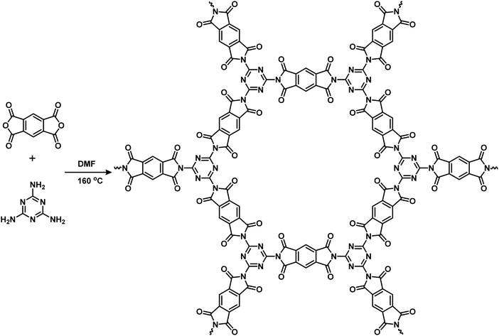
The TP-COF network was prepared by a condensation reaction of melamine and PMDA in the presence of DMF at reflux conditions, as shown in Scheme 1. After 72 h of reaction, a white insoluble powder was obtained as TP-COF with a yield of 55%. The TP-COF was fully characterized by different spectroscopic techniques, SEM imaging, and surface and structural analysis. As shown in Fig. S1a of ESI,† the UV-vis spectra of TP-COF thin-film revealed a broad absorption with two major peaks at around 280 and 320 nm. These peaks originated from the π–π* transitions in the triazine-based polyimide network. The optical bandgap of the TP-COF was determined by using the Kubelka–Munk function and the corresponding Tauc plot (in Fig. S1b in ESI†). The derived optical bandgap was 3.25 eV, which defined the TP-COF as good semiconducting material that may be suitable for electrocatalytic applications. The FT-IR spectrum (shown in Fig. S2a in ESI†) of the TP-COF displayed a complete disappearance of the primary –NH2 peak at 3420 and 3470 cm−1 with the appearance of two carbonyl (C![[double bond, length as m-dash]](https://www.rsc.org/images/entities/char_e001.gif) O) stretching peaks at 1735 and 1790 cm−1. Moreover, TP-COF exhibited 1640, 1574, and 1125 cm−1 peaks corresponding to the C
O) stretching peaks at 1735 and 1790 cm−1. Moreover, TP-COF exhibited 1640, 1574, and 1125 cm−1 peaks corresponding to the C![[double bond, length as m-dash]](https://www.rsc.org/images/entities/char_e001.gif) N stretching in triazine, C
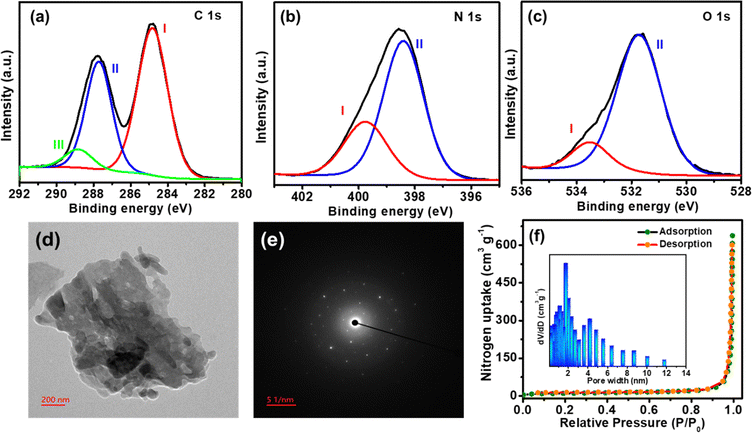
N stretching in triazine, C![[double bond, length as m-dash]](https://www.rsc.org/images/entities/char_e001.gif) C in benzene, and C–N in the imide unit. The chemical composition and bonding environment of TP-COF were examined by X-ray photoelectron spectroscopy (XPS). The fitting of C 1s core level XPS spectra of TP-COF in Fig. 1a disclosed the peaks at 288.8 eV (peak I: for C
C in benzene, and C–N in the imide unit. The chemical composition and bonding environment of TP-COF were examined by X-ray photoelectron spectroscopy (XPS). The fitting of C 1s core level XPS spectra of TP-COF in Fig. 1a disclosed the peaks at 288.8 eV (peak I: for C![[double bond, length as m-dash]](https://www.rsc.org/images/entities/char_e001.gif) O groups), 287.7 eV (peak II: C
O groups), 287.7 eV (peak II: C![[double bond, length as m-dash]](https://www.rsc.org/images/entities/char_e001.gif) N in triazine), 284.8 eV (peak III: C
N in triazine), 284.8 eV (peak III: C![[double bond, length as m-dash]](https://www.rsc.org/images/entities/char_e001.gif) C in aromatic benzene). The N 1s core-level XPS spectra of TP-COF, as shown in Fig. 1b, fitted in 399.7 (peak I: imide moieties) and 398.4 (peak II: for triazine moieties). The O 1s peak of TP-COF in Fig. 1c was fitted into two peaks at 533.5 eV (peak I: carbonyl groups) and 531.7 (peak II: quinone groups). Overall, the XPS results specified the construction of a polyimide-type skeleton with triazine rings in the synthesized TP-COF.
C in aromatic benzene). The N 1s core-level XPS spectra of TP-COF, as shown in Fig. 1b, fitted in 399.7 (peak I: imide moieties) and 398.4 (peak II: for triazine moieties). The O 1s peak of TP-COF in Fig. 1c was fitted into two peaks at 533.5 eV (peak I: carbonyl groups) and 531.7 (peak II: quinone groups). Overall, the XPS results specified the construction of a polyimide-type skeleton with triazine rings in the synthesized TP-COF.
The powder X-ray diffraction (PXRD) study showed a semi-crystalline nature of TP-COF, as evidenced by the broad peaks (Fig. S2b in ESI†). The peak positions were matched with the earlier literature.48 The SEM images of TP-COF in Fig. S2c in ESI† revealed the presence of 2D nanoflakes with a highly stacked structure. The HRTEM images of TP-COF, as shown in Fig. 1d, revealed similar nanoflakes. The Selected Area Electron Diffraction SAED imaging of TP-COF in Fig. 1e suggested the semi-crystalline nature of the synthesized TP-COF. The elemental distribution on TP-COF was studied using TEM-EDX mapping (Fig. S3 in ESI†), demonstrating a homogeneous distribution of C, N, and O as the elements throughout the surface of the COF. The porous structure and specific surface area of TP-COF were examined by N2 adsorption–desorption isotherm analysis at 77 K. The TP-COF disclosed a type III adsorption isotherm curve (shown in Fig. 1f) according to the IUPAC classification, indicating the presence of both micropores and mesopores in the materials. The calculated BET (Brunauer–Emmett–Teller) surface area of TP-COF was 312.6 m2 g−1 with an average pore size of 1.8 nm and a total pore volume of 0.25 cc g−1, respectively. These results suggest that the catalysts with hierarchically porous structures would be superior towards electrocatalytic HER reaction.
In the TGA study, as shown in Fig. S4 (ESI†), the TP-COF revealed excellent thermal stability as it disclosed only 4% weight loss until 400 °C. Strong π–π stacking induced high aggregation between the COF structures, and the extended conjugation in the polymeric network could be the reason for the high stability of the TP-COF. Thermal decomposition started around 400 °C, and a 40% weight loss was seen in the 400 and 500 °C regions due to the collapsing polymeric frameworks. Again, the TGA plot also revealed a weight loss of 90% up to 800 °C, which led to the decomposition and carbonization of the material. The HRTEM and corresponding SAED analysis (Fig. S5 in ESI†) of the TP-CPF pyrolyzed at 400 °C, 500 °C, and 800 °C was performed to support the discussion mentioned above in the TGA study. The TEM and SAED images of the sample pyrolyzed at 400 °C revealed a similar pattern of nanoflakes and semicrystalline nature like the TP-COF, showing no thermal degradation till 400 °C. The sample, pyrolyzed at 500 °C, exposed the formation of a sheet-like structure with no such crystallinity, owing to the collapsing polymeric frameworks. The pyrolysis at a high temperature of 800 °C produced carbon sheets with only a single crystalline plane (002).
To prepare the N-doped carbon materials from TP-COF, the pristine TP-COF was pyrolyzed in three different temperatures of 600, 700, and 800 °C under the N2 atmosphere, yielding the TP-COF-C600, TP-COF-C700, and TP-COF-C800, respectively. All the COF-derived carbon samples were fully characterized by powder X-ray diffraction (PXRD), Raman spectroscopy, and BET surface analysis. The PXRD pattern in Fig. 2a revealed the existence of a broad peak at 2θ = 25.6°, attributing to the (002). The pattern revealed the lack of long-range order rather than the complete amorphous nature of TP-COF-C samples.49 The Raman spectra of the carbonized samples in Fig. 2b disclosed the presence of two distinct peaks at 1360 and 1590 cm−1 due to the typical D (defect and disorder) and G (graphitic) band of the TP-COF-C samples. The Raman intensities ratio of those bands (ID/IG) generally reveals the degree of structural disorder and the intensity of the defect.50 The ID/IG values were calculated as 1.13, 0.99, and 0.95 for TP-COF-C600, TP-COF-C700, and TP-COF-C800, respectively. Here, the prominent decrease of ID/IG values from TP-COF-C600 to TP-COF-C800 suggests a higher degree of graphitization level with increasing pyrolysis temperature.
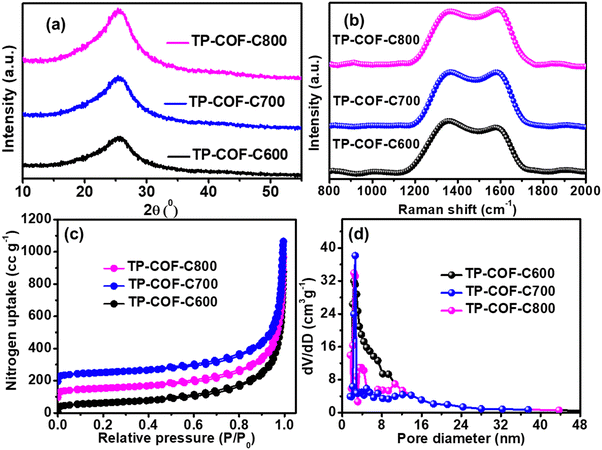 | ||
| Fig. 2 (a) PXRD pattern and (b) Raman spectra of TP-COF-C samples. (c) Nitrogen adsorption–desorption isotherm and (d) the corresponding pore size distribution plot of all the TP-COF-C samples. | ||
The porosity and surface area of pyrolyzed TP-COF-C samples were further examined by N2 adsorption–desorption analysis at 77 K. From Fig. 2c, the calculated BET surface area of TP-COF-C600, TP-COF-C700, and TP-COF-C800 were 516.7, 672.2 and 628.2 m2 g−1, respectively, which was much higher than the pristine TP-COF. The data indicated that the TP-COF-C700 had the highest surface area among the pyrolyzed samples. Furthermore, the pore size distribution plot in Fig. 2d revealed that the total pore volume of 0.25, 0.59, and 0.47 cc g−1 with the average pore sizes of 3.96, 1.98, and 2.24 nm for TP-COF-C600, TP-COF-C700, and TP-COF-C800, respectively. The porosities of the TP-COF-C samples were increased due to the liberation of produced gasses during the pyrolysis process, and it could be highly beneficial for elevating the catalytic activity of the carbonous materials. These results suggested that the catalysts with hierarchically porous structures would be superior towards electrocatalytic HER reaction. However, after a specific temperature of pyrolysis (700 °C), the COF precursor might lead to serious structural collapse to provide a slight decrement in surface area and total pore volume in TP-COF-C-800.49 Based on the observations mentioned above from PXRD, BET, and Raman spectroscopy of TP-COF-C samples, we can conclude that TP-COF-C700 had a better combination of graphitization, surface area, and porosity that made TP-COF-C700 as the best electrocatalyst among all pyrolyzed carbon compounds.
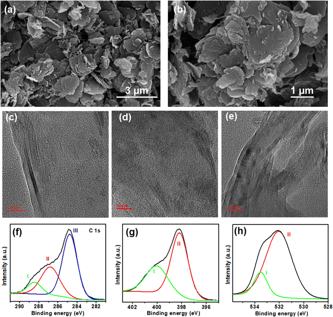
The surface morphology of TP-COF-C700 was investigated by FESEM analysis. The FESEM images of TP-COF-C700, as shown in Fig. 3a and b, revealed more uniform 2D nanosheet-type structures. It was also envisioned that all the carbonized TP-COF-C samples exhibited higher surface area than the pristine COF, possibly due to the formation of the uniform 2D nanosheet structures after pyrolysis. The TEM images of TP-COF-C-600, TP-COF-C-700, and TP-COF-C-800, as shown in Fig. S6 in ESI,† divulged the similar nanosheet structures of the COF-derived materials. The temperature-dependent graphitization of pristine TP-COF was further examined by HRTEM analysis for different TP-COF samples. The HRTEM images of TP-COF-C-600, TP-COF-C-700, and TP-COF-C-800, as shown in Fig. 3c–e, revealed a significant increment of graphitic layers with increasing temperature. In the TP-COF-C-800 sample, the formation of ordered graphitic layers was maximum compared to other carbon samples, confirming the increment of graphitization in the COF-derived materials with enhanced temperature. Furthermore, the chemical composition and bonding environment of TP-COF-C700 were examined by core-level XPS spectra. Notionally, only three units- triazine, imide, and benzene comprised the COF network. Upon pyrolysis at 700 °C, these units may remain unchanged or transformed into pyridine and graphite-type carbons. When fitted, the core level C1s spectrum yielded three distinct peaks (Fig. 3f) positioned at 288.4, 286.8, and 284.8 eV attributed to C![[double bond, length as m-dash]](https://www.rsc.org/images/entities/char_e001.gif) O groups (peak I), C
O groups (peak I), C![[double bond, length as m-dash]](https://www.rsc.org/images/entities/char_e001.gif) N in triazine (peak II), C
N in triazine (peak II), C![[double bond, length as m-dash]](https://www.rsc.org/images/entities/char_e001.gif) C in aromatic benzene (peak III), respectively. In addition, the N 1s core-level XPS spectra in Fig. 3g were fitted in two peaks at 400.0 for imide moieties (peak I) and 398.1 for triazine moieties (peak II). Finally, the core-level O 1s peak in Fig. 3h was deconvoluted into 533.5 eV for carbonyl (peak I) and 532.0 eV for quinone-type moieties (peak II). Overall, the XPS data revealed that the obtained carbonized materials mainly retained the parent COF skeletons with triazine, pyridinic, and extended aromatic carbon sheets. However, the change of surface elemental composition of TP-COF and TP-COF-C700 derived from the XPS study is compared and given in Table S1 of ESI.†
C in aromatic benzene (peak III), respectively. In addition, the N 1s core-level XPS spectra in Fig. 3g were fitted in two peaks at 400.0 for imide moieties (peak I) and 398.1 for triazine moieties (peak II). Finally, the core-level O 1s peak in Fig. 3h was deconvoluted into 533.5 eV for carbonyl (peak I) and 532.0 eV for quinone-type moieties (peak II). Overall, the XPS data revealed that the obtained carbonized materials mainly retained the parent COF skeletons with triazine, pyridinic, and extended aromatic carbon sheets. However, the change of surface elemental composition of TP-COF and TP-COF-C700 derived from the XPS study is compared and given in Table S1 of ESI.†
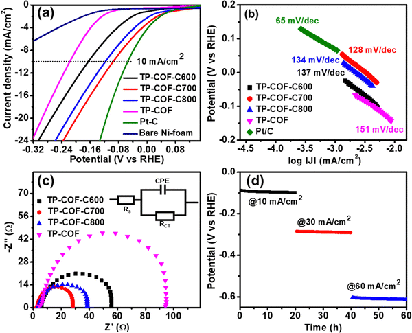
The enriched N-doped carbon and abundant pores with high pore volumes and the surface area support TP-COF-C samples to display favourable electrocatalytic HER activity. The HER electrocatalytic activities of TP-COF-C samples and parent TP-COF were examined by linear sweep voltammetry (LSV) measurement in 1 M KOH solution using a typical three-electrode electrochemical set-up, and the results were compared with state-of-the-art catalyst Pt/C. The LSV polarization curves, as shown in Fig. 4a, divulged that the TP-COF-C samples exhibited an overpotential of 162, 95, and 117 mV for TP-COF-C600, TP-COF-C700, and TP-COF-C800, respectively, to reach the 10 mA cm−2 current density. However, the bare Ni-foam exhibited a very low current density, suggesting a negligible HER activity. On the other hand, the pristine TP-COF demonstrated a higher (182 mV@10 mA cm−2) overpotential than the N-doped carbon samples. The observation mentioned above suggested that the overpotential value of TP-COF-C700 was the lowest among the carbon materials and way lower than the parent TP-COF. However, the overpotential value of TP-COF-C700 was slightly higher than the commercially available 20% Pt/C catalyst (55 mV@10 mA cm−2). It is to be noted that the TP-COF-C700 is a completely metal-free carbon compound, and its HER activity was superior or very comparable with other reported metal-free catalysts, as depicted in Table S2 (ESI†). The excellent surface area, porosity, and effective electronegative N-doping in TP-COF-C700 greatly enhanced the electrical conductivity, water adsorption on the catalyst surface, and better ion diffusion during electrochemical reactions, resulting in low overpotential. TP-COF-C700 exhibited the highest surface area and porosity among the TP-COF-C samples, demonstrating the lowest overpotential compared to other samples.
To get further insight into HER kinetics for proton reduction on the surface of the catalysts and electrochemical mechanism, the Tafel slopes were evaluated from the LSV plot. Generally, in alkaline media, the generation of hydrogen through HER from the catalyst surface involves the following three steps:32,33
| Step 1: Volmer: H2O + e− → Hads + HO− |
| Step 2: Heyrovsky: H2O + Hads + e− → H2 + HO− |
| Step 3: Tafel: Hads + Hads → H2 |
The catalytic activity of TP-COF-C700 can be understood by unveiling the ECSA calculation. The ECSA can be obtained from the materials’ electrochemical double-layered capacitance (Cdl). From Fig. S7 in ESI,† the Cdl value of TP-COF-C700 was estimated as 8.2 mF. The ECSA and Rf of TP-COF-C700 were determined as 136.67 cm−2 and 162.7, respectively. The high ECSA for TP-COF-C700 suggested the higher accessibility of catalytic electrochemical surface benefiting from the abundant porous structure. Besides, the stability of the catalytic performances is another important criterion for evaluating industrial applicability. The long-term performance of TP-COF-C700 towards HER was examined by time-dependant chronopotentiometry at different applied current densities of 10, 30, and 60 mA cm−2. As shown in Fig. 4d, the chronopotentiometry plot unveiled the stable HER response for more than 60 h with the potential outputs of −0.096, −0.287, and −0.603 V (vs. RHE) at the abovementioned current densities. The faradaic efficiency (FE) is one of the most crucial parameters to determine the energy efficiency of the catalyst. In this regard, TP-COF-C700 revealed its potential for efficiently utilizing electrical energy for hydrogen generation. The FE of TP-COF-C700 was determined by measuring the hydrogen content produced during HER by the water displacement method, as shown in Fig. S8 in ESI.†![[thin space (1/6-em)]](https://www.rsc.org/images/entities/char_2009.gif) 51–53 The FE of TP-COF-C700 was calculated as 98%, which was very close to the ideal value of 100%.
51–53 The FE of TP-COF-C700 was calculated as 98%, which was very close to the ideal value of 100%.
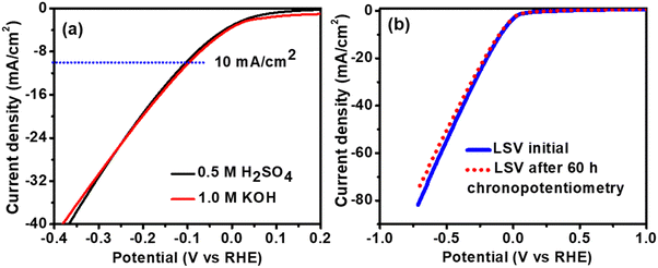
The abovementioned experiments suggested that our TP-COF-C700 electrocatalyst is highly efficient in alkaline electrolytes. To evaluate the HER efficacy of our TP-COF-C700 in acidic electrolytes also, we have assessed the electrocatalytic HER performance of TP-COF-C700 using 0.5 M H2SO4 as electrolyte. The LSV curve, as shown in Fig. 5a, revealed similar HER activity in both electrolyte conditions with similar overpotentials. The result indicated the robust HER performance of the TP-COF-C700 catalyst, which is entirely independent of pH. The electrochemical HER stability and robustness of the catalyst structure of TP-COF-C700 were further analysed by LSV measurement after long-term chronopotentiometry performances. As shown in Fig. 5b, the carbon-based porous catalyst TP-COF-C700 revealed an almost unchanged LSV curve after 60 h of chronopotentiometry.
The structural stability and robustness of TP-COF-C700 were further analyzed by SEM imaging, PXRD, and XPS analysis after 60 h of chronopotentiometry. The post-chronopotentiometry observation suggests that TP-COF-C700 retained almost unchanged nanosheet type morphology (as shown in Fig. 6a). The PXRD pattern in Fig. 6b highlighted the unchanged structural stability of TP-COF-C700 upon electrochemical performances. Moreover, the bonding environment of TP-COF-C700 after HER was checked by XPS analysis. The XPS spectra of TP-COF-C700 in Fig. 6c–e for C 1s, N 1s, and O 1s showed similar elemental peaks after chronopotentiometry. The surface composition after electrocatalysis derived from XPS is provided in Table S1 (ESI†). The data depicted that the surface compositions were not altered after the electrocatalysis, confirming the excellent stability of the TP-COF-C700 electrocatalyst. These exceptional observations in electrocatalytic HER performance highlight the immense potential of TP-COF-C-700 as a versatile material for hydrogen generation for green energy applications.
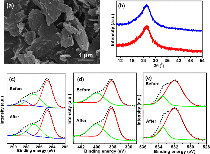 | ||
| Fig. 6 (a) SEM image of TP-COF-C700 after 60 h chronopotentiometry. (b) PXRD pattern, (c) C 1s, (d) N 1s, and (e) O 1s core-level XPS spectra of TP-COF-C700 before and after chronopotentiometry. | ||
4. Conclusion
In summary, we have successfully synthesized TP-COF, a pyromellitic diimide and triazine-based porous COF, which exhibited a complete metal-free electrocatalytic HER performance at a low overpotential of 182 mV to reach a current density of 10 mA cm−2. The electrocatalytic HER activity of TP-COF was further increased after pyrolyzing the TP-COF at 700 °C to prepare the N-doped porous carbon nanosheet, TP-COF-C700. The TP-COF-C700 exhibited a high surface area of 672.2 m2 g−1 with uniform mesopores of 1.98 nm diameter, facilitating superior HER activity. The TP-COF-C700 showed pH-independent HER performances with an overpotential of 94 mV@10 mA cm−2, high HER faradaic efficiency of 98%, and ultra-robust durability of more than 60 h. These inspiring outcomes can be attributed to the COF-derived N-doped carbon nanosheet's high surface area and abundant inherent pores with high electrical conductivities. The presence of the N atom facilitates proton adsorption in the nanosheet surface, contributing to its superior HER performance. This exceptional durability in electrocatalytic performance highlights the immense potential of TP-COF-C700 as a potential material for hydrogen generation towards green energy applications.Conflicts of interest
There are no conflicts to declare.Acknowledgements
C. C. acknowledges the BITS Pilani Hyderabad Campus for ACRG (BITS/GAU/ACRG/2021/H0778) grant and Department of Science and Technology, Government of India, for providing instrumental facilities through PURSE Project No. SR/PURSE/2020/20 (G) at BITS Pilani Hyderabad Campus. S. H. is thankful to the DST INSPIRE PhD program for fellowship.References
- W. Zhou, J. Jia, J. Lu, L. Yang, D. Hou and G. Li, Recent developments of carbon-based electrocatalysts for hydrogen evolution reaction, Nano Energy, 2016, 28, 29–43 CrossRef CAS.
- S. Y. Bae, J. Mahmood, I. Y. Jeon and J. B. Baek, Recent advances in ruthenium-based electrocatalysts for the hydrogen evolution reaction, Nanoscale Horiz., 2020, 5, 43–56 RSC.
- Y. Zhang, H. Ren, T. Gao, J. Mou, Y. Meng and G. Tan, Solvent-controlled NiCoP with diversified morphology generated from a solvent vapour thermal reaction for electrocatalytic hydrogen evolution, Mater. Today Energy, 2020, 17, 100477 CrossRef.
- C. Zhou, T. Gao, J. Tan, Z. Luo, L. Mutallip and D. Xiao, Synthesis of flower-like nickel–iron–chromium nanostructure compound deposited stainless steel foil as an efficient binder-free electrocatalyst for water splitting, Sustainable Energy Fuels, 2021, 5, 2649–2659 RSC.
- F. Li, G. F. Han, H. J. Noh, I. Ahmad, I. Y. Jeon and J. B. Baek, Mechanochemically Assisted Synthesis of a Ru Catalyst for Hydrogen Evolution with Performance Superior to Pt in Both Acidic and Alkaline Media, Adv. Mater., 2018, 30, 1803676 CrossRef PubMed.
- C. Hu, Y. Gao, L. Zhao and L. Dai, Carbon-based metal-free electrocatalysts: Recent progress and forward looking, Chem Catal., 2022, 2, 2150–2156 CrossRef CAS.
- M. Sheng, B. Jiang, B. Wu, F. Liao, X. Fan and H. Lin, Approaching the Volcano Top: Iridium/Silicon Nanocomposites as Efficient Electrocatalysts for the Hydrogen Evolution Reaction, ACS Nano, 2019, 13, 2786–2794 CrossRef CAS PubMed.
- G. Gao, Y. Jiao, E. R. Waclawik and A. Du, Single Atom (Pd/Pt) Supported on Graphitic Carbon Nitride as an Efficient Photocatalyst for Visible-Light Reduction of Carbon Dioxide, J. Am. Chem. Soc., 2016, 138, 6292–6297 CrossRef CAS PubMed.
- N. Kaeffer, A. Morozan, J. Fize, E. Martinez, L. Guetaz and V. Artero, The Dark Side of Molecular Catalysis: Diimine-Dioxime Cobalt Complexes Are Not the Actual Hydrogen Evolution Electrocatalyst in Acidic Aqueous Solutions, ACS Catal., 2016, 6, 3727–3737 CrossRef CAS.
- P. Prabhu, V. Jose and J. M. Lee, Design strategies for development of TMD-based heterostructures in electrochemical energy systems, Matter, 2020, 2, 526–553 CrossRef.
- H. Wang, X. Xiao, S. Liu, C. L. Chiang, X. Kuai and C. K. Peng, Structural and electronic optimization of MoS2 edges for hydrogen evolution, J. Am. Chem. Soc., 2019, 141, 18578–18584 CrossRef CAS PubMed.
- H. Wang, J. Chen, Y. Lin, X. Wang, J. Li and Y. Li, Electronic modulation of non-van der Waals 2D electrocatalysts for efficient energy conversion, Adv. Mater., 2021, 33, 2008422 CrossRef CAS PubMed.
- P. Prabhu and J. M. Lee, Metallenes as functional materials in electrocatalysis, Chem. Soc. Rev., 2021, 50, 6700–6719 RSC.
- H. Wang and M. J. Lee, Recent advances in structural engineering of MXene electrocatalysts, J. Mater. Chem. A, 2020, 8, 10604–10624 RSC.
- H. Wang, Y. Lin, S. Liu, J. Li, L. Bu and J. Chen, Confined growth of pyridinic N-Mo2C sites on MXenes for hydrogen evolution, J. Mater. Chem. A, 2020, 8, 7109–7116 RSC.
- Y. Lin, H. Wang, C. K. Peng, L. Bu, C. L. Chiang and K. Tian, Co-induced electronic optimization of hierarchical NiFe LDH for oxygen evolution, Small, 2020, 16, 2002426 CrossRef CAS PubMed.
- M. Li, H. Li, X. Jiang, M. Jiang, X. Zhan and G. Fu, Gd-induced electronic structure engineering of a NiFe-layered double hydroxide for efficient oxygen evolution, J. Mater. Chem. A, 2021, 9, 2999–3006 RSC.
- J. R. McKone, B. F. Sadtler, C. A. Werlang, N. S. Lewis and H. B. Gray, Ni–Mo nanopowders for efficient electrochemical hydrogen evolution, ACS Catal., 2013, 3, 166–169 CrossRef CAS.
- X. Tang, L. Xiao, C. Yang, J. Lu and L. Zhuang, Noble fabrication of Ni–Mo cathode for alkaline water electrolysis and alkaline polymer electrolyte water electrolysis, Int. J. Hydrog. Energy, 2014, 39, 3055–3060 CrossRef CAS.
- T. P. Nguyen, S. Choi, J. M. Jeon, K. C. Kwon, H. W. Jang and S. Y. Kim, Transition metal disulfide nanosheets synthesized by facile sonication method for the hydrogen evolution reaction, J. Phys. Chem. C, 2016, 120, 3929–3935 CrossRef CAS.
- T. P. Nguyen, D. L. T. Nguyen, V. H. Nguyen and T. H. Le, Facile synthesis of WS2 hollow spheres and their hydrogen evolution reaction performance, Appl. Surf. Sci., 2020, 505, 144574 CrossRef CAS.
- Z. Pu, I. S. Amiinu, Z. Kou, W. Li and S. Mu, RuP2-based catalysts with platinum-like activity and higher durability for the hydrogen evolution reaction at all pH values, Angew. Chem., Int. Ed., 2017, 56, 11559–11564 CrossRef CAS PubMed.
- F. H. Saadi, A. I. Carim, E. Verlage, J. C. Hemminger, N. S. Lewis and M. P. Soriaga, CoP as an acid-stable active electrocatalyst for the hydrogen-evolution reaction: electrochemical synthesis, interfacial characterization and performance evaluation, J. Phys. Chem. C, 2014, 118, 29294–29300 CrossRef CAS.
- A. Eftekhari, Electrocatalysts for hydrogen evolution reaction, Int. J. Hydrog. Energy, 2017, 42, 11053–11077 CrossRef CAS.
- S. Sarkar and S. C. Peter, An overview on Pd-based electrocatalysts for the hydrogen evolution reaction, Inorg. Chem. Front., 2018, 5, 2060–2080 RSC.
- Q. Zhai, Y. Pan and L. Dai, Carbon-Based Metal-Free Electrocatalysts: Past, Present, and Future, Acc. Mater. Res., 2021, 2, 1239–1250 CrossRef CAS.
- J. W. Park, G. Park, M. Kim, M. Han, J. Jang, Y. Yamauchi, B. Yuliarto, P. Krüger, J. Kim, N. Park and H. Lim, Ni-single atom decorated mesoporous carbon electrocatalysts for hydrogen evolution reaction, Chem. Eng. J., 2023, 468, 143733 CrossRef CAS.
- M. Kim, K. L. Firestein, J. F. Fernando, X. Xu, H. Lim, D. V. Golberg, J. Na, J. Kim, H. Nara, J. Tang and Y. Yamauchi, Strategic design of Fe and N co-doped hierarchically porous carbon as superior ORR catalyst: from the perspective of nanoarchitectonics, Chem. Sci., 2022, 13, 10836–10845 RSC.
- S. Xu, M. Niu, G. Zhao, S. Ming, X. Li, Q. Zhu, L. X. Ding, M. Kim, A. A. Alothman, M. S. S. Mushab and Y. Yamauchi, Size control and electronic manipulation of Ru catalyst over B, N co-doped carbon network for high-performance hydrogen evolution reaction, Nano Res., 2023, 16, 6212–6219 CrossRef CAS.
- Y. Ito, W. Cong, T. Fujita, Z. Tang and M. Chen, High catalytic activity of nitrogen and sulfur co-doped nanoporous graphene in the hydrogen evolution reaction, Angew. Chem., Int. Ed., 2015, 54, 2131–2136 CrossRef CAS PubMed.
- W. Cui, Q. Liu, N. Cheng, A. M. Asiri and X. Sun, Activated carbon nanotubes: a highly-active metal-free electrocatalyst for hydrogen evolution reaction, Chem. Commun., 2014, 50, 9340–9342 RSC.
- S. Bhunia, S. K. Das, R. Jana, S. C. Peter, S. Bhattacharya, M. Addicoat, A. Bhaumik and A. Pradhan, Electrochemical Stimuli-Driven Facile Metal-Free Hydrogen Evolution from Pyrene-Porphyrin-Based Crystalline Covalent Organic Framework, ACS Appl. Mater. Interfaces, 2017, 9, 23843–23851 CrossRef CAS PubMed.
- B. C. Patra, S. Khilari, R. N. Manna, S. Mondal, D. Pradhan, A. Pradhan, A. Bhaumik and A. Metal-Free, Covalent Organic Polymer for Electrocatalytic Hydrogen Evolution, ACS Catal., 2017, 7, 6120–6127 CrossRef CAS.
- Y. Y. Wu, J. M. Veleta, D. Y. Tang, A. D. Price, C. E. Botez and D. Villagran, Efficient electrocatalytic hydrogen gas evolution by a cobalt-porphyrin-based crystalline polymer, Dalton Trans., 2018, 47, 8801–8806 RSC.
- S. L. Qiao, B. Y. Zhang, Q. Li, Z. Li, W. B. Wang, J. Zhao, X. J. Zhang and Y. Q. Hu, Pore Surface Engineering of Covalent Triazine Frameworks@MoS2 Electrocatalyst for the Hydrogen Evolution Reaction, ChemSusChem, 2019, 12, 5032–5040 CrossRef CAS PubMed.
- H. Nishihara and T. Kyotani, Templated nanocarbons for energy storage, Adv. Mater., 2012, 24, 4473–4498 CrossRef CAS PubMed.
- L. L. Zhang and X. S. Zhao, Carbon-based materials as supercapacitor electrodes, Chem. Soc. Rev., 2009, 38, 2520–2531 RSC.
- J. P. Paraknowitsch and A. Thomas, Doping carbons beyond nitrogen: an overview of advanced heteroatom doped carbons with boron, sulphur and phosphorus for energy applications, Energy Environ. Sci., 2013, 6, 2839–2855 RSC.
- J. Zhao, H. Lai, Z. Lyu, Y. Jiang, K. Xie, X. Wang, Q. Wu, L. Yang, Z. Jin, Y. Ma, J. Liu and Z. Hu, Hydrophilic hierarchical nitrogen-doped carbon nanocages for ultrahigh supercapacitive performance, Adv. Mater., 2015, 27, 3541–3545 CrossRef CAS PubMed.
- B. You, F. Kang, P. Yin and Q. Zhang, Hydrogel-derived heteroatom-doped porous carbon networks for supercapacitor and electrocatalytic oxygen reduction, Carbon, 2016, 103, 9–15 CrossRef CAS.
- W. Tian, Q. Gao, Y. Tan, K. Yang, L. Zhu, C. Yang and H. Zhang, Bio-inspired beehive-like hierarchical nanoporous carbon derived from bamboo-based industrial by-product as a high-performance supercapacitor electrode material, J. Mater. Chem. A, 2015, 3, 5656–5664 RSC.
- Y. Zhou, Y. Leng, W. Zhou, J. Huang, M. Zhao, J. Zhan, C. Feng, Z. Tang, S. Chen and H. Liu, Sulfur and nitrogen self-doped carbon nanosheets derived from peanut root nodules as high-efficiency non-metal electrocatalyst for hydrogen evolution reaction, Nano Energy, 2015, 16, 357–366 CrossRef CAS.
- J. Hou, C. Cao, F. Idrees and X. Ma, Hierarchical porous nitrogen-doped carbon nanosheets derived from silk for ultrahigh-capacity battery anodes and supercapacitors, ACS Nano, 2015, 9, 2556–2564 CrossRef CAS PubMed.
- W. Qian, F. Sun, Y. Xu, L. Qiu, C. Liu, S. Wang and F. Yan, Human hair-derived carbon flakes for electrochemical supercapacitors, Energy Environ. Sci., 2014, 7, 379–386 RSC.
- Y. Gao, G. Hu, J. Zhong, Z. Shi, Y. Zhu and D. S. Su, Nitrogen-Doped sp2-Hybridized Carbon as a Superior Catalyst for Selective Oxidation, Angew. Chem., Int. Ed., 2013, 52, 2109–2113 CrossRef CAS PubMed.
- L. Yang, J. Shui, L. Du, Y. Shao, J. Liu and L. Dai, Carbon-Based Metal-Free ORR Electrocatalysts for Fuel Cells: Past, Present, and Future, Adv. Mater., 2019, 31, 1804799 CrossRef PubMed.
- K. Gong, F. Du, Z. Xia, M. Durstock and L. Dai, Nitrogen-Doped Carbon Nanotube Arrays with High Electrocatalytic Activity for Oxygen Reduction, Science, 2009, 323, 760–764 CrossRef CAS PubMed.
- H. Duan, P. Lyu, J. Liu, Y. Zhao and Y. Xu, Semiconducting Crystalline Two-Dimensional Polyimide Nanosheets with Superior Sodium Storage Properties, ACS Nano, 2019, 13, 2473–2480 CAS.
- M. Wang, J. Yang, S. Liu, X. Che, S. He, G. Chen and J. Qiu, Nitrogen-doped porous carbon electrode for aqueous iodide redox supercapacitor, Chem. Eng. J., 2023, 451, 138501 CrossRef CAS.
- C. Thomsen and S. Reich, Double resonant Raman scattering in graphite, Phys. Rev. Lett., 2000, 85, 5214 CrossRef CAS PubMed.
- N. Gupta, S. Halder, R. P. Behere, P. Singh, S. Kanungo, M. Dixit, C. Chakraborty and B. K. Kuila, Side-Chain Modification in Conjugated Polymer Frameworks for the Electrocatalytic Oxygen Evolution Reaction, ACS Appl. Mater. Interfaces, 2023, 15, 29042–29051 CrossRef CAS PubMed.
- S. Halder, A. K. Pradhan, P. Sivasakthi, P. K. Samanta and C. Chakraborty, Engineering S, N-doped carbon nanosheets derived from thiazolothiazole-based conjugated polymer for efficient electrocatalytic oxygen evolution and Zn-air battery, Mater. Today Chem., 2023, 32, 101649 CrossRef CAS.
- S. Halder and C. Chakraborty, Triazine-Based Two-Dimensional Porous Covalent Organic Framework for Efficient Electrode Materials for Electrocatalytic Hydrogen Generation and Hybrid Supercapacitors, ACS Appl. Eng. Mater., 2023, 1, 1799–1808 CrossRef CAS.
Footnote |
| † Electronic supplementary information (ESI) available. See DOI: https://doi.org/10.1039/d3ya00325f |
| This journal is © The Royal Society of Chemistry 2023 |

