DOI:
10.1039/D3YA00102D
(Review Article)
Energy Adv., 2023,
2, 948-964
Energy storage mechanism, advancement, challenges, and perspectives on vivid manganese redox couples
Received
6th March 2023
, Accepted 10th May 2023
First published on 10th May 2023
Abstract
Recently, aqueous-based redox flow batteries with the manganese (Mn2+/Mn3+) redox couple have gained significant attention due to their eco-friendliness, cost-effectiveness, non-toxicity, and abundance, providing an efficient energy storage solution for sustainable grid applications. However, the construction of manganese-based redox flow batteries remains difficult due to severe intrinsic issues, including poor cyclability and limited capacity. During the past few decades, several scientific attempts have been made to alleviate the issues fundamentally enabling a pathway for high performance redox flow batteries. Herein, various developments of manganese-based redox flow batteries are methodically understood and reviewed. Moreover, the charge storage chemical reaction mechanism of manganese redox couples under various conditions is conferred providing an excellent opportunity to design scalable, affordable and environmentally benevolent manganese-based redox flow batteries for futuristic grid applications. The remaining challenges are tabulated and the authors’ perspectives are highlighted for the highly promising manganese redox couple.

R. Naresh
| Mr R. Naresh is currently a doctoral student at the Electrochemical Power Sources Division, CSIR-Central Electrochemical Research Institute, Karaikudi, India. He received his MSc (Chemistry) degree in 2018 from Bharathidasan University, Tiruchirappalli, India. He is exploring and researching the fundamentals of manganese redox couples for redox flow battery applications, towards his doctoral degree under the guidance of Prof. P. Ragupathy. |

Vilas G. Pol
| Vilas G. Pol is a Professor of Chemical Engineering at Purdue University, IN, USA. He has authored/co-authored >255 research publications (h index 54), and is an inventor on 16 issued US patents and 25+ applications. He has more than 25 years of research experience in the fields of energy storage, materials chemistry, engineering and electrochemistry. He has delivered hundreds of invited, keynote and plenary talks including ‘TEDx’. He has been honored with multiple awards from professional AIChE, ACS, MRS, ACerS, TMS and Carbon societies. Purdue University honored him with Outstanding Engineering Teachers, Seed for Success, Most Impactful Inventors, Bravo, and Purdue Faculty Scholar awards. There are two ‘Guinness World Records’ to his name. |

P. Ragupathy
| P. Ragupathy is an Associate Professor at Electrochemical Power Sources Division, CSIR-Central Electrochemical Research Institute, Karaikudi, India. He obtained his PhD degree in Materials Electrochemistry from the Indian Institute of Science, Bangalore, India. During his graduation, he visited ICMCB, Bordeaux, France on a Cellules Mixtes de Recherche Fellowship. Before becoming a Research Fellow at Nanyang Technological University and NUS Nanoscience and Nanotechnology Initiative at Singapore, he worked as a Postdoctoral Fellow at The University of Texas at Austin. Among many accolades, he was honored with a prestigious Raman Research Fellowship by CSIR at Purdue University, USA and Brain Pool Fellowship by Korea Research Foundation, South Korea at KAIST. His research interests include materials science and electrochemistry with special emphasis on electrochemical energy systems such as lithium technology (Li-ion, Li-S and Li-air) redox flow batteries and supercapacitors. |
1. Introduction
The world's energy production and consumption primarily depend on sources of fossil fuels, such as coal, petroleum products, and natural gas. However, fossil fuels are non-renewable sources, and severe utilization leads to fast depletion of fossil fuels and environmental issues such as global warming and CO2 emission.1 The electricity generated from the combustion of coal produces greenhouse gases which settle in Earth's outer atmosphere causing global warming.2 This scenario can be effectively overcome by producing electricity from renewable resources such as solar, wind, and tides due to their clean and inexhaustible nature.3 However, the intermittent nature of certain renewable sources such as solar and wind substantially increases the complexity of electricity generation.4
In order to use renewable energy sources effectively, the development of an energy storage system with low cost, eco-friendliness, and high performance is always desirable. The electrochemical energy storage (EES) technology is one of the potential candidates owing to its advantageous features such as high performance, long cyclability, cleanliness, scalability, and high performance for storing energy from renewable resources.5,6 Hence, integrating renewable sources of energy with EES technologies would be a better choice to sustain the energy demand. There has been significant development in EES technologies such as Li-ion batteries,7 lead-acid batteries,8 and supercapacitors.9 Among these, Li-ion batteries are well commercialized and widely utilized in portable and vehicle applications in day-to-day life.10 Moreover, the expensive nature and lower abundance of lithium impedes grid-level energy storage applications. The limited energy density, poor cyclability (less than 1000 cycles), toxic nature of lead, and use of sulfuric acid in lead-acid batteries relatively hamper their widespread application. The intrinsic nature of low energy density of supercapacitors make them not the right choice for grid-level energy storage applications. Thus, the development of state of the art EES systems is urgently required to meet the global demand effectively, especially storing energy at a large scale. In this regard, redox flow batteries (RFBs) are widely recognized for large scale energy storage applications due to the decoupling of the power and energy densities, long cycle life, scalability, depth of discharge, cost effectiveness, and easy battery fabrication process.11,12
The energy can be stored in RFBs by dissolving redox active molecules in a suitable solvent, which is constantly pumped into the cell stack wherein the actual redox reactions take place. During charging, the energy is stored by the oxidation of the catholyte and reduction of an anolyte, whereas when discharging, the energy is utilized by the reverse redox process.13,14 The choosing of an appropriate redox couple is the most important part, as it determines the cell voltage and energy density of the battery. The perfect redox couple should possess some intrinsic characteristics, such as high reversibility, high solubility, and high chemical stability. At present, various redox couples have been proposed such as Zn/Br2,15,16 all vanadium,17 Zn/Ce,18 Zn/V,19 polysulfide/iodide,20 all iron.21 Among various flow batteries investigated during the past, zinc bromine and all vanadium systems are very familiar and also successfully commercialized around the world. Though zinc/bromine and all vanadium are well studied systems, they still have some issues that need to be addressed. The high corrosive nature of electrogenerated bromine severely affects the battery components and significantly reduces the lifetime of the system. Apart from that, the non-uniform deposition of zinc during charging causes dendrite formation, which leads to puncturing of the separator resulting in battery failure. In the case of all vanadium RFBs, the use of high cost Nafion-117 membrane, toxic vanadium metal, low energy density, and use of acidic electrolyte makes grid-level energy storage applications more of a challenge. The all iron RFBs are another most appealing candidate for energy storage due to their low cost, eco-friendliness, and non-toxicity.22 However, they possess significant challenges such as low stability, poor cycling performance, and susecptability to aerial oxidation.23 Hence, the development of novel redox couples which enable high performance and affordable cost advanced RFBs is very much essential for sustainable energy storage applications.
Manganese-based batteries are one of the oldest chemistries and a well familiar technology across the world for primary batteries owing to their enormous benefits, such as moderate cost, eco-friendliness, abundance (8th most abundant metal), and high theoretical capacity.24,25 Manganese has a wide range of valences ranging from Mn2+ to Mn7+, allowing for extensive electrochemistry in Mn-based materials. The manganese-based batteries have been classified into two broad categories such as first generation and second generation based on the primary charge storage mechanisms.26 The first generation manganese-based batteries involve solid-state conversion reactions (Generation 1A) and intercalation reactions (Generation 1B) of the manganese dioxide (MnO2) cathode. Alkaline electrolytes have been frequently used in generation 1A manganese-based batteries. However, the use of an alkaline medium limits the cyclability and capacity of the MnO2 cathode; the major reason for this is due to the sluggish conversion reaction between MnO2 and the reduced Mn2O3, so it hampers the full utilization of two electrons.27 In generation 1B, mild aqueous electrolytes are widely used in manganese-based batteries, in which metal cations undergo an intercalation/deintercalation mechanism with the MnO2 cathode in the Zn/MnO2 battery.28,29 However, the long-term cycling of Zn/MnO2 batteries using mild aqueous electrolytes revealed poor capacities at high charge/discharge rates due to the structural collapse during the solid-state intercalation/deintercalation process. The second generation manganese-based batteries have gained significant attention in recent years due to the deposition/stripping mechanism of the Mn2+/MnO2 redox couple, which has various advantageous features such as two-electron redox process, high theoretical capacity (616 mA h g−1), a high standard reduction potential of 1.23 V vs. SHE, and being completely free from cathode properties i.e., avoiding structural collapse.30 Recently, the Mn2+/Mn3+ redox couple has emerged as a prominent redox couple for redox flow battery applications due to the liquid–liquid state reaction of Mn2+/Mn3+ redox species, which eventually eliminates structural collapse or flow field blocking. Interestingly, the standard redox potential of the Mn2+/Mn3+ (1.51 V vs. SHE) redox couple is much higher than that of Mn2+/MnO2, MnO2/MnOOH, MnO2/ZnxMnO2, and most of the redox couples. Therefore, it is easy to achieve high cell voltage RFB devices by pairing Mn2+/Mn3+ with a low redox potential redox couple. Thus, Mn2+/MnO2 and Mn2+/Mn3+-based batteries are considered as viable alternatives for large-scale energy storage.
2. Significance of the manganese redox couple in RFBs
Manganese-based redox couples have gained significant interest in energy storage and conversion devices due to their high standard reduction potential, high abundance, corrosive free nature, eco-friendliness, non-toxicity, one/two electron transfer, high solubility, existence of variable oxidation states, and good reversibility. Fig. 1 illustrates the salient features of the manganese redox couple for not only battery and supercapacitor applications but also for highly adaptable redox flow batteries. More impressively, the standard reduction potential of the Mn2+/Mn3+ redox couple is 1.51 V vs. SHE, which is higher than that of many redox couples reported so far. Thus, the extended cell voltage of Mn2+/Mn3+ exactly reflects the overall energy density of RFB by combining with an appropriate counter redox couple with lower reduction potential. Therefore, the Mn2+/Mn3+ redox couple is ideally recognized as a promising catholyte for RFBs. Moreover, a deep understanding of the manganese properties is most essential to construct a high performance RFB system. For instance, a Frost diagram portrays an inherent stability of oxidation states and tells more about the thermodynamic stability of the species, such as how much a species is prone to oxidation or reduction. The species located below in the plot are lower in free energy as they are thermodynamically more stable and resist undergoing a disproportionation reaction, as shown in Fig. 2(a). Accordingly, the compounds with Mn2+ are the most stable states among other oxidation states. The species Mn3+ and MnO42− readily undergo disproportionation reaction as shown in eqn (1) and (2).| | | 2Mn3+ + 2H2O → MnO2 + Mn2+ + 4H+ | (1) |
| | | 3MnO42− + 4H+ → MnO2 + 2MnO4− + 2H2O | (2) |
In addition to that, a Pourbiax diagram also helps to determine the thermodynamically stable species at a given potential and pH. The species having a strong oxidizing power (MnO4− is a strong oxidizing agent) are found at the top of the Pourbiax plot, whereas species having a strong reducing power (Mn0 is a strong reducing agent) are located at the bottom of the plot, as depicted in Fig. 2(b). When the predominant area of oxidation state of the species disappears completely above or below at a particular pH, then the species will easily undergo a disproportionation reaction, such as MnO42−. Thus, Frost and Pourbiax diagrams significantly aid in probing the mechanistic understanding of the manganese redox process in cell reactions.
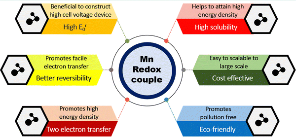 |
| | Fig. 1 Pictorial representation of the merits of the manganese redox couple for RFB applications. | |
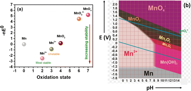 |
| | Fig. 2 Representation of the redox stability of manganese: (a) frost diagram, and (b) Pourbiax diagram.31 | |
3. Understanding the charge storage mechanism of Mn2+/MnO2 and Mn2+/Mn3+ redox chemistry
With the aim to thoroughly understand the mechanistic process of the charge storage of the Mn2+/MnO2 redox couple, researchers have attempted several techniques such as electrochemical, microscopic, and theoretical studies. For instance, Donne et al.32 used a rotating disc electrode (RDE) and a rotating ring disc electrode (RRDE) to probe the MnO2 deposition on the electrode under acidic conditions. These results showed that electrodeposition of MnO2 involves the formation of Mn3+ as an intermediate; it undergoes hydrolysis and precipitation to generate MnOOH as in dilute H2SO4 (<1 M), which is then oxidized to form MnO2. For higher concentration H2SO4 (>1 M), practically all of the electrogenerated Mn3+ dissolves into the solution, where it has been proposed that Mn3+–Mn3+ collisions with subsequent disproportionation result in MnO2 precipitation. Thus, the pH and nature of the substrate play a vital role in determining the deposition of MnO2. Similarly, Huang et al.33 extensively studied the deposition/dissolution of MnO2 on carbon felt using the cyclic voltammetric technique. The MnO2 deposition/dissolution can be followed by two plausible mechanistic pathways, as shown in eqn (3) to (11). From the cyclic voltammetry observation, when the anodic potential is below 1.18 V vs. Ag/AgCl there is only one cathodic peak seen and this indicates that the redox reactions favor mechanistic pathway 1. Interestingly, on slightly increasing the potential to 1.2 V vs. Ag/AgCl there is a sudden increase in anodic current and two cathodic peaks are obtained. Thus, the redox reactions proceed via mechanistic pathway 2 over pathway 1, respectively.
Mechanistic pathway: 1
Deposition of MnO2
| | | Mn2+ → Mn3+ + e− Electrochemical process | (3) |
| | | 2Mn3+ → Mn2+ + Mn4+ Chemical process | (4) |
| | | Mn4+ + 2H2O → MnO2 + 4H+ Chemical process | (5) |
Dissolution of MnO2
| | | MnO2 + 4H+ + 2e− → Mn2+ + 2H2O Electrochemical process | (6) |
Mechanistic pathway: 2
Deposition of MnO2
| | | Mn2+ → Mn3+ + e− Electrochemical process | (7) |
| | | Mn3+ + 2H2O → MnOOH + 3H+ Chemical process | (8) |
| | | MnOOH → MnO2 + H+ + e− Electrochemical process | (9) |
Dissolution of MnO2
| | | MnO2 + H+ + e− → MnOOH Electrochemical process | (10) |
| | | MnOOH + 3H+ + e− → Mn2+ + 2H2O Electrochemical process | (11) |
The schematic diagram of the Mn2+/MnO2 mechanistic process is displayed in Fig. 3. It is seen that the conversion of Mn2+ to MnO2 involves multistep electrochemical and chemical redox reactions, which mainly depend on pH, nature of the substrate, and working electrode potential. During the charging process, the Mn2+ was oxidized to form an unstable intermediate Mn3+ in the first step, which was then substantially converted into a thermodynamically stable insoluble product such as MnO2via either pathway 1 or 2 depending upon the conditions. The formed MnO2 gets deposited/passivated on the electrode surface. During the discharging process, the deposited MnO2 is dissolved back into the electrolyte in the form of Mn2+ ions. The electrogenerated intermediate Mn3+ is easily prone to disproportionation reaction to form Mn2+ and MnO2, which eventually leads to decay of the battery capacity. In this concern, to mitigate the Mn3+ disproportionation reaction, researchers have attempted to bypass the formation of Mn3+ by using a chronoamperometric electrodeposition process (constant voltage charging mode) in which Mn2+/MnO2 conversion (i.e., liquid/solid two-electron conversion reaction) can be attained directly.35–37 Furthermore, to achieve effective Mn2+/MnO2 conversion, additives are introduced such as inorganic compounds, and redox mediators.38–41
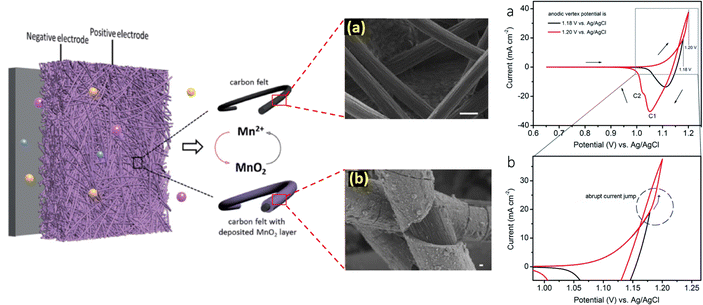 |
| | Fig. 3 Understanding the mechanism of Mn2+/MnO2 redox chemistry and the corresponding cyclic voltammogram profile (reproduced from ref. 33 with permission from The Royal Society of Chemistry) (reproduced from ref. 34 with permission from The Royal Society of Chemistry). | |
The Mn2+/Mn3+ redox couple is another fascinating chemistry in which both the Mn2+ and Mn3+ conversion reactions are in the liquid state and exhibited a high standard reduction potential of +1.51 V vs. SHE. Hence, utilizing the Mn2+/Mn3+ redox couple as the catholyte enhances the cell voltage as well as the energy density of the redox flow batteries. However, the main issue of Mn2+/Mn3+ conversion is the instability of Mn3+ in a neutral medium as it is spontaneously disproportionated to MnO2. It can be stabilized by using hard ligands such as F−, PO43−, SO42−, and C2O42−. Since the Mn2+/Mn3+ redox couple involves liquid–liquid state conversion in aqueous electrolytes, it can be only suitable for redox flow batteries. To enhance the reversibility of the Mn2+/Mn3+ redox couple, increasing the H+ ion concentration is highly required to stabilize the electrogenerated Mn3+, respectively.42 A schematic diagram of the manganese redox couples and comparison of the Mn2+/Mn3+ and Mn2+/MnO2 characteristics is presented in Fig. 4.
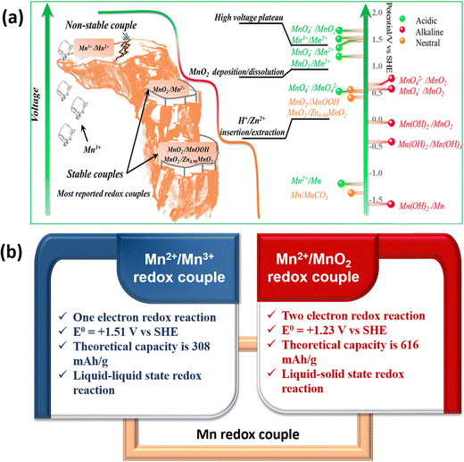 |
| | Fig. 4 (a) Schematic illustration of manganese redox couples in different electrolytes (reproduced from ref. 43 with permission from the American Chemical Society) and (b) comparison of Mn2+/Mn3+ and Mn2+/MnO2 redox couple characteristics. | |
4. Development of manganese-based redox flow batteries
In the last few years, much progress has been made in manganese-based redox flow batteries. To provide a general overview, we have meticulously examined previous reports as mentioned in Fig. 5. The present review discusses the cutting edge studies on the manganese-based RFBs.
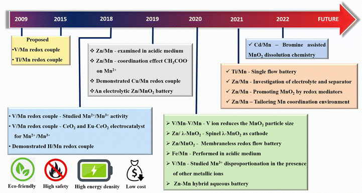 |
| | Fig. 5 Historical timeline for the development of new generation manganese based RFBs. | |
4.1 Ti/Mn redox couple
Dong et al.44 proposed the TiO2+/Ti3+ redox couple as an anolyte in Ti/Mn RFBs due to its high abundance, high solubility (>3 M in water), and enhanced electrochemical activity. The reported Ti/Mn RFB exhibited a cell voltage of 1.41 V. The basic electrochemical redox reaction occurs in the Ti/Mn system as shown below.
| Cathode: Mn3+ + e− ↔ Mn2+ E0 = +1.51 V vs. SHE |
| Anode: Ti3+ + H2O ↔ TiO2+ + 2H+ + e− E0 = +0.1 V vs. SHE |
| Net cell reaction: TiO2+ + Mn2+ ↔ Mn3+ + Ti3+ Ecell = 1.41 V |
It is well known that disproportionation of Mn3+ is one of the critical issues found in manganese-based compounds. This scenario can be effectively addressed by adopting a mixed electrolyte of Ti and Mn in both the tanks. Interestingly, it is beneficial for Mn3+ ions, as it can be stabilized by Ti4+ ions and suppresses the disproportionation reaction. Moreover, the significant shift in reduction potential was observed from 0.97 to 1.1 V for the mixed electrolyte due to the reduction reaction rate of MnO2/Mn2+, which can be enhanced by Ti4+ ions. The presence of Ti4+ largely influences the morphology of MnO2 with a particle size of 5 nm. The absence of Ti4+ electrolyte leads to a bulbous cactus like morphology of MnO2 with the size of 2 μm. Thus, the incorporation of Ti4+ controls the MnO2 particle growth as well as the disproportionation of Mn3+.
The cell assembled with mixed electrolyte delivered a maximum energy density of 23.5 kW h m−3. The cell exhibits a stable cycling performance over 40 cycles with 99.8% (CE), 86.9% (VE), and 86.7% (EE). Similarly, Qiao et al.45 have designed a novel Ti/Mn single flow battery with a static manganese cathode by eliminating the pump and an electrolyte tank. The electrolyte filled carbon felt was used as the cathode and only the negative electrolyte was circulated. This novel cell architecture avoids the risk of MnO2 flow field blocking, and water transfer, and inhibits aerial oxidation of the active material. The electrolyte composition used in this work includes 0.5 M MnSO4 + 1 M TiOSO4 + 3 M H2SO4 and 0.5 M MnSO4 + 3 M H2SO4, respectively. The Ti/Mn single flow battery with 0.5 M MnSO4 + 1 M TiOSO4 + 3 M H2SO4 showed a greater charge discharge performance with 99% (CE). Very interestingly, the presence of Ti effectively controls disproportionation of MnO2, which is reflected in the overall cell performance. The electrolyte without Ti additive exhibited poor capacity retention and a drastic drop in the CE. This is mainly due to massive deposition of MnO2 on the electrode. The Ti/Mn single flow cell exhibited a stable cycling performance over 1000 cycles with 99% (CE) at a current density of 40 mA cm−2. Recently, Nan et al.46 also used titanium as an electrolyte additive as it facilitates the MnO2 reduction reaction during the discharge process by an electrostatic attraction of titanium, as shown in Fig. 6(a). Furthermore, the positive electrolyte tank was pumped downwards from the electrolyte tank to the flow cell, as it provides better mass transfer of residual MnO2 to the electrode surface, as shown in Fig. 6(b). This modified electrolyte tank structure along with the titanium additive improved the cycle life for about 1000 cycles with 99.5% of CE, and 85% of EE, respectively.
 |
| | Fig. 6 Schematic illustration of (a) the TiOSO4 additive in the V–Mn flow battery and (b) the improved electrolyte tank structure (reproduced from ref. 46 with permission from Elsevier). | |
4.2 H2/Mn redox couple
Recently, gas/liquid phase systems also known as regenerative fuel cells (RFCs) have emerged as a potential candidate for large scale energy storage. The main advantage of using a gas/liquid hybrid system by replacing the negative electrolyte with a gas such as hydrogen is that it mitigates the crossover of reactive species during the cell reaction and the gas/liquid are easily separated from each other. A lot of work has been demonstrated on RFCs using halogen redox couples as the catholyte, specifically the H2/Br2 hybrid system, which has a high energy density of 40 W h L−1.47,48 However, the corrosive nature of bromine affects the cell components severely and leads to poor compatibility. This issue can be minimized by employing bromine capturing agents (BCA) such as 1-ethylpyridinium bromide, 1-alkylpyridin-1-ium bromides, and 1-alkyl-3-methylimidazol-1-ium bromides to suppress the vapor pressure of bromine.49–51 Yet, the strong interaction between BCA and anionic groups in the proton exchange membrane decreases the proton conductivity as it reduces the voltage efficiency of the system. Moreover, crossover of Br−/Br3− species results in the degradation of the hydrogen oxidation/evaluation catalyst.52,53 So, significant attention has been paid to the development of H2/inorganic metal hybrid systems owing to its abundant inorganic metals, low cost, and eco-friendliness. For instance, the H2/Ce redox couple was reported but its practical application is seriously limited by the sluggish kinetics of Ce3+/Ce4+.54 Garcia et al.55 proposed a H2/Mn RFC, in which it offers a practical energy density of 30 W h L−1 and delivered a maximum power density of 1410 mW cm−2. The hydrogen/manganese redox couple is used to construct a new type of redox flow battery where Mn and H2 are positive and negative half redox reactions, respectively as shown below. The net cell voltage of the H/Mn system is 1.51 V.
| Cathode: Mn3+ + e− ↔ Mn2+ E0 = +1.51 V vs. SHE |
| Anode: 2H+ + 2e− ↔ H2(g) E0 = 0 V vs. SHE |
| Net cell reaction: H2 + Mn2+ ↔ H+ + Mn3+ Ecell = 1.51 V |
The H2–Mn flow battery performance was tested at various current densities, as shown in Fig. 7(a). The H2–Mn RFB with additive exhibits a better charge discharge profile at different current densities. At 75, 100 and 150 mA cm−2, the H–Mn flow battery reaches a maximum discharge capacity of 534, 498 and 432 mA h, respectively. This demonstrates a highly desirable performance and exceptional electrolyte consumption with values that are near to the theoretical value of 536 mA h. The presence of an additive significantly enhances the stability of Mn3+ by a weak interaction between Mn3+ and Ti4+via oxo bridge ligands. More impressively, the cell displayed a high CE of 98.5% even at 150 mA cm−2 current density. Moreover, at a high concentration of manganese electrolyte, the H–Mn RFC shows 75% of EE with greater than 99% coulombic efficiency, as shown in Fig. 7(b).
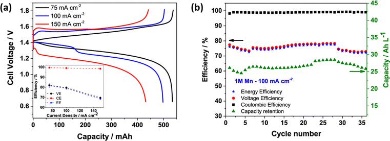 |
| | Fig. 7 (a) Galvanic charge discharge performance recorded at different current densities, and (b) H–Mn flow battery performance at 100 mA cm−2; electrolyte: 1 M MnSO4 + 3 M H2SO4 + 1 M Ti(SO4)2, Hydrogen: 100 mL min−1, Flow rate: 50 mL min−1, respectively.55 | |
4.3 Fe/Mn redox couple
The iron redox couples are the most appealing candidates for RFBs owing to their low cost, ecofriendliness, non-toxicity, high solubility, abundance, and steady electrochemical reversibility. For instance, various iron-based RFBs have been proposed over the past decades such as Fe/Cr,56 Fe/V,57 Fe/Cd,58 Fe/Pb,59 all iron,60 and Zn/Fe61 RFBs, respectively. However, every system has its own critical issues which need to be addressed. An electrocatalyst and high temperature of 65 °C are required to boost the kinetics of the Cr3+/Cr2+ redox couple in Fe/Cr RFB. The use of an expensive Nafion membrane is necessary to minimize the crossover of vanadium in Fe/V RFB. The low ionic resistance and blocking effect of electrodeposited cadmium result in lower battery performance in Fe/Cd RFB. The use of toxic and heavy metal lead in Fe/Pb RFB limits its application in large scale energy storage. An all iron RFB on the other hand possesses significant merits such as low cost, eco-friendliness, and high abundance of iron sources. However, Fe2+/Fe0 conversion requires a controlled atmosphere to stabilize the zero valent elemental iron. Moreover, iron is a very good catalyst for the HER and hence it triggers the HER at the anode, which eventually reduces the coulombic efficiency of the battery.62
The zinc dendrite formation at high current density operation also affects the operational current density and cycle life. Therefore, to overcome these critical issues the development of novel redox couples is highly demanded. Archana et al.63 demonstrated the Fe/Mn redox couple in a RFB operated under acidic conditions (methanesulfonic acid used as the supporting electrolyte). The positive and negative half redox reactions of the Fe/Mn system are shown below.
| Cathode: Mn3+ + e− ↔ Mn2+ E0 = +1.56 V vs. SHE |
| Anode: Fe3+ + e− ↔ Fe2+ E0 = +0.77 V vs. SHE |
| Net cell reaction: Fe3+ + Mn2+ ↔ Fe2+ + Mn3+ Ecell = 0.79 V |
The net cell voltage of the Fe/Mn system is 0.79 V. Though the net cell voltage is lower than other existing systems, the solubility of both metal precursors is exorbitantly high with good electrochemical reversibility; hence it is easy to achieve high energy density RFBs. Moreover, the use of methanesulfonic acid is highly beneficial for enhancing the reversibility of the Mn
2+/Mn
3+ redox couple by the coordinating effect of the methanesulfonate ligand. The methanesulfonate coordinates with Mn
2+ ions and forms a coordinate complex which stabilizes the Mn
3+ ions and greatly reduces the rate of disproportionation reaction. The rate performance of the flow cell was tested at different current densities such as 6 to 10 mA cm
−2 and displayed a better charge discharge performance, as shown in
Fig. 8(a). However, the Fe/Mn system adopted with methanesulfonic acid as a supporting electrolyte shows a stable performance over 100 cycles with CE of 96%, VE of 70%, and EE of 67.20%, as shown in
Fig. 8(b). Similarly, Jing Wu
et al.64 overcame the MnO
2 precipitates by using HCl as a supporting electrolyte for the Fe/Mn RFB. The presence of HCl is highly beneficial for preventing MnO
2 precipitates by forming a stable and reversible [MnCl
4(H
2O)
2]
− complex.
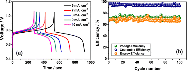 |
| | Fig. 8 (a) The GCD performance recorded at different current densities and (b) the cyclability profile of Fe/Mn RFB (reproduced from ref. 63 with permission from Elsevier). | |
4.4 Cu/Mn redox couple
The copper based redox couples have also attracted enormous attention for grid level energy storage due to them being less toxic, eco-friendly, cheap, abundant and high purity, and highly soluble in water.65 Lloyd et al.66,67 proposed an all copper RFB based on the chemistry of copper, which shows three oxidation states such as Cu2+, Cu1+, and Cu0 by constructing Cu+/Cu as the anolyte and Cu2+/Cu+ as the catholyte, respectively. However, the cell voltage of the all copper RFB is too low (0.67 V), which is relatively lower than conventional RFBs, and the unstable oxidation state of Cu1+ undergoes a disproportionation reaction which limits the RFB performance. In this regard, Wei et al.68 reported Cu/Mn RFB chemistry in acidic conditions (dil·H2SO4 as supporting electrolyte), which exhibits a cell voltage of 1.18 V, which is higher than the all copper RFB system. The positive and negative half redox reactions of the Cu/Mn system are shown below.
| Cathode: Mn3+ + e− ↔ Mn2+ E0 = +1.51 V vs. SHE |
| Anode: Cu2+ + 2e− ↔ Cu E0 = +0.33 V vs. SHE |
| Net cell reaction: 2Mn2+ + Cu2+ ↔ 2Mn3+ + Cu Ecell = 1.18 V |
The rate capability of the Cu/Mn system was analyzed at various current densities at 5, 10, and 20 mA cm−2 as shown in Fig. 9(a) and it exhibited a CE of 92.8, 93.4, and 94%, respectively as shown in Fig. 9(b). The Cu/Mn RFB exhibited an EE of 83.1, 78.5, and 76.2%, respectively, as shown in Fig. 9(c). The cell maintains a capacity of 7.5 A h L−1 at all operating current densities, as shown in Fig. 9(d). Moreover, the Mn/Cu RFB showed a long cycling performance with 92.4% (CE) and maintains a stable EE of 79% over 100 cycles at 10 mA cm−2 current density.
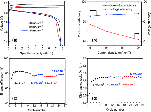 |
| | Fig. 9 (a) The GCD profile of Cu/Mn RFB at different current densities, (b) CE and VE plot, (c) EE plot, and (d) discharge capacity vs. cycle plot (reproduced from ref. 69 with permission from Elsevier). | |
4.5 V/Mn redox couple
The all vanadium RFB is a well developed technology and widely used in industry for grid level energy storage. Despite these persuasive merits, it is still impeded by low energy efficiency, low cell voltage (1.25 V), and low energy density (25 W h kg−1). Therefore, an alternative RFB system with high cell voltage and high practical energy density is urgently needed to fulfill the energy demand. In connection with this, Hong et al.70 replaced the positive redox couple (V4+/V5+) in the all vanadium RFB with the Mn2+/Mn3+ redox couple owing to its high standard reduction potential (1.51 V vs. SHE), low cost, and eco-friendliness. The proposed V/Mn system exhibits a cell voltage of 1.77 V, which is very close to the cell voltage of ZnBr2 (1.84 V). The positive and negative half redox reactions of the V/Mn system are explained as follows.
| Cathode: Mn3+ + e− ↔ Mn2+ E0 = +1.51 V vs. SHE |
| Anode: V3+ + e− ↔ V2+ E0 = −0.25 V vs. SHE |
| Net cell reaction: Mn2+ + V3+ ↔ Mn3+ + V2+ Ecell = 1.77 V |
The demonstrated V/Mn system showed an impressive flow cell performance with an average CE of 92.5%, VE of 85.3%, and EE of 81.2%. The obtained flow cell efficiencies are 20% higher than that of the all vanadium RFB system and displayed an average discharge voltage of 1.66 V, which is also 14% higher than that of the all vanadium RFB system. Moreover, the V/Mn RFB system delivered a maximum energy density of 40.8 W h kg−1, which is twice that of the all vanadium system. Lee et al.71 analyzed the MnO2 precipitation during the RFB cycling performance. It was observed that very interesting results were obtained during the cycling to investigate the stability of the electrolyte. The dark brown precipitate of MnO2 was noticed for the 1st discharge process and a large quantity of precipitates was found after the 10th cycle. More remarkably, the precipitate starts to diminish after the 25th cycle and completely disappeared after the 50th cycle.
Inductively coupled plasma (ICP) spectroscopy reveals that there is a change in vanadium and manganese concentration during the cycling performance. The presence of vanadium ions in the positive electrolyte was highly influenced by the particle size of the MnO2 and decreased from 620 nm to 230 nm after the 25th cycle. Interestingly, the permeation of vanadium ions from the anolyte to the catholyte decreases the MnO2 particle size due to an increase of coulombic repulsion between the particles, and as a result it increases the energy density of the battery, as shown in Fig. 10(b). Similarly, Park et al.72 employed a multiple redox couple that is a mixture of vanadium and manganese in both anolyte and catholyte to eliminate the MnO2 precipitation during the battery performance. The manganese in the negative electrolyte cannot participate in the reaction; instead it avoids crossover. The presence of vanadium ions in the positive electrolyte controls the particle size of the MnO2 very effectively. It was observed that after the 1st cycle charge of the V/Mn system, a deep brown precipitate of MnO2 with an average particle size of 621 nm was observed. Whereas for the V–Mn/V–Mn system, the precipitate was not a deep brown color but appeared in centrifugation with an average size of 73 nm, as shown in Fig. 10(a). Thus, increasing the vanadium ion concentration increases the zeta potential of the MnO2 and as a result it reduces the particle size of the MnO2. The V–Mn/V–Mn system displayed a greater energy density of 35.2 W h L−1 compared to V/V (21.1 W h L−1), and V/Mn (31 W h L−1), as shown in Fig. 10(b). This is due to the increased number of redox active ions as well as the operating cell voltage.
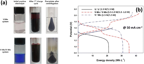 |
| | Fig. 10 (a) Photographic images of MnO2 deposition in the V/Mn and V–Mn/V–Mn system and (b) GCD profile recorded at 50 mA cm−2 (reproduced from ref. 72 with permission from Elsevier). | |
Furthermore, to enhance the electrochemical performance of the Mn2+/Mn3+ redox couple, Rodrigues et al.73 utilized CeO2 and europium (Eu)-doped CeO2 film electrocatalysts. The europium-doped CeO2, i.e., Ce0.99Eu0.01O2, shows better performance even at a higher current density operation (>3.2 mA cm−2) and exhibited stable performance over 500 cycles, which delivered a maximum specific capacity of 372.49 mA h g−1 when compared to CeO2 (334.84 mA h g−1). In continuation of this, Reynard et al.74 investigated the Mn3+ stability in the presence of other metal ions such as V5+ and Ti4+ at equimolar ratio (Mn2+, Mn2+:Ti4+, Mn2+:V5+, and Mn2+:V5+:Ti4+) in acidic conditions. The cyclic voltammetry illustrates that, for Mn2+ a single anodic peak was obtained at +1.72 vs. SHE, which is a characteristic conversion between Mn2+ to Mn3+ and two reduction peaks were noticed at +1.51 V vs. SHE (attributed to Mn3+ to Mn2+ conversion) and +1.12 V vs. SHE (attributed to MnO2 to Mn2+ conversion). For Mn2+:Ti4+, the MnO2 to Mn2+ conversion peak is shifted by 30 mV to a cathodic potential of +1.09 V vs. SHE and also lower anodic current was obtained. This indicates that Ti4+ makes a complex with Mn3+, protecting it from disproportionation. In the presence of V5+, the MnO2 to Mn2+ conversion peak was observed at +1.5 V vs. SHE and it indicates the sluggish disproportionation of Mn3+. The surface morphology of the passivated electrode provides valuable information. In the case of carbon felt electrodes, there is a thick deposition of MnO2 of 500 nm for the manganese electrolyte, as shown in Fig. 11(a). Interestingly, the presence of other metal ions such as titanium, vanadium/titanium, and vanadium significantly reduces the formation of MnO2 and reduces the thickness of MnO2 to <100 nm, as shown in Fig. 11(b)–(d). In the case of the glassy carbon electrode surface, for Mn2+ a thick layer of cactus-like particles of MnO2 with larger than 1 μ diameter was observed, as shown in Fig. 11(e). For Mn2+:Ti4+, a reduced amount of MnO2 deposition was observed, as shown in Fig. 11(f). Interestingly Mn2+:V5+, and Mn2+:V5+:Ti4+, displayed a different structural existence of the oxide layer, as shown in Fig. 11(g) and (h). Moreover, the XPS analysis illustrates the formation of V2O5 particles due to oxidation of metal ions at the electrode surface. Among these, V5+ has a higher stabilizing tendency towards Mn3+ than that of Ti4+. Hence V5+ ions would be the best additive for constructing high performance V/Mn RFBs and provide high interest for manganese-based redox flow battery applications.
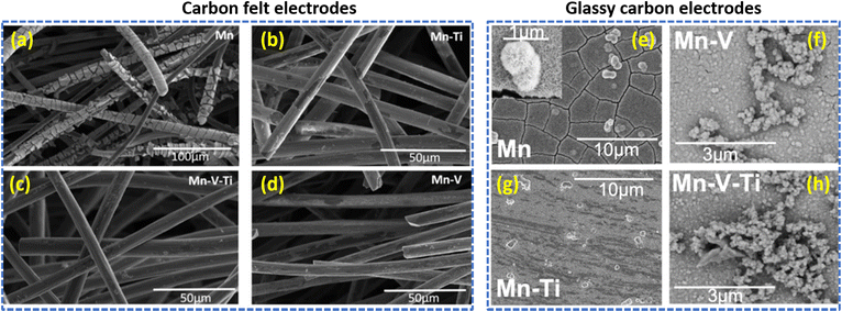 |
| | Fig. 11 SEM images of electrodeposited MnO2 on the carbon felt electrodes (a)–(d) and on the glassy carbon electrodes (e)–(h), respectively (reproduced from ref. 74 with permission from Wiley-VCH). | |
4.6 Zn/Mn redox couple
Aqueous zinc-based redox flow batteries hold great promise for potential application in large scale energy storage and are particularly attractive due to high safety, high redox kinetics of the Zn2+/Zn redox couple, high theoretical capacity (820 mA h g−1, 5855 mA h cm−3), stable metallic zinc, low redox potential (−0.76 V vs. SHE), and low cost.75,76 So far, various zinc-based flow batteries have been developed, such as Zn/Ce,77 Zn/Br2,78 and Zn/I279 RFBs. Among these, only the Zn/Br2 system is greatly attractive for large scale energy storage due to its high cell voltage (1.84 V) and high theoretical energy density (440 W h kg−1). However, the corrosive nature of bromine severely affects the cell components and is extremely harmful to the environment. Thus, the development of an efficient catholyte is highly demanded for large scale energy storage. In connection to this, Zhang et al.80 replaced the Br−/Br2 redox couple with the Mn2+/Mn3+ redox couple and successfully demonstrated a hybrid Zn/Mn RFB. The Zn/Mn RFB exhibits a cell voltage of 2.27 V, which is higher than that of the Zn/Br2 RFB. Moreover, the specific theoretical energy density of Zn/Mn RFB is calculated to be 674 W h kg−1 which is almost twice that of the Zn/Br RFB. The electrochemical reaction that occurs in the positive and negative half redox reactions of the Zn/Mn system is shown below.
| Cathode: Mn3+ + e− ↔ Mn2+ E0 = +1.51 V vs. SHE |
| Anode: Zn2+ + 2 e− ↔ Zn E0 = −0.76 V vs. SHE |
| Net cell reaction: Zn2+ + Mn2+ ↔ Zn + Mn3+ Ecell = 2.27 V |
Moreover, methanesulfonic acid (MSA) is employed as a supporting electrolyte and it also minimizes the MnO2 deposition on the felt. The presence of MSA increases the stability of Mn3+ ions by a coordinating effect. Thus, the Zn/Mn flow cell adopted with MSA as a supporting electrolyte exhibits a CE of 92.2% and EE of 74%, respectively. Xie et al.34 for the first time demonstrated an aqueous Zn/Mn RFB with high reversibility by increasing the conductivity of the electrode by carbon coating (carbon black). Interestingly, the Mn(OAc)2 precursor can be charged to MnO2 directly, as shown in Fig. 12(a) and (b), which is entirely different from the chemistry of MnSO4, where it leads to the formation of Mn3+ and as a result it readily undergoes disproportionation to form a solid product MnO2, as shown in Fig. 12(a) and (c). The acetate ligand in the Mn(OAc)2 strongly coordinated to the Mn2+, which is beneficial for better electrochemical redox reaction, which was further confirmed from the P2O74− test. The Zn/Mn RFB with 0.5 M Mn(OAc)2 precursor exhibited an EE of 78% at 40 mA cm−2 current density, as shown in Fig. 12(d). Furthermore, the assembled battery exhibits stable performance over 400 charge–discharge cycles without capacity fading, as shown in Fig. 12(e). The rate capability of Zn/Mn RFB shows the better charge discharge performance over wide current density operations, as shown in Fig. 12(f). More remarkably, the Zn/Mn RFB exhibited stable performance even at high loading of carbon black (16 mg cm−2), as shown in Fig. 12(g).
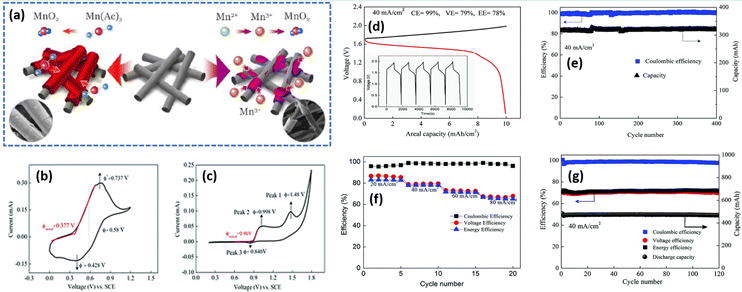 |
| | Fig. 12 (a) Schematic representation of the electrochemical performance of Mn(Ac)2 and MnSO4 electrolyte, cyclic voltammetry profile of the glassy carbon electrode recorded at a scan rate of 10 mV s−1 in (b) 0.05 M Mn(Ac)2 in 1 M KCl and (c) 0.05 M MnSO4 in 0.5 M K2SO4, (d) GCD profile of Zn/Mn RFB recorded at 40 mA cm−2, (e) capacity retention and the coulombic efficiency plot with 7 mA h cm−2, (f) the rate capability of Zn/Mn RFB observed at different current density, and (g) cyclability of Zn/Mn RFB with 10 mA h cm−2 at 40 mA cm−2 (reproduced from ref. 34 with permission from The Royal Society of Chemistry). | |
In our work, we investigated the electrolyte composition and separator for aqueous zinc manganese RFBs. Among various electrolyte compositions, sulfate-based precursors exhibit a significant performance over the others. The Zn/Mn flow cell suffered from serious crossover of the electrolytes and this issue can be solved by incorporating pore filling agent (polyacrylonitrile) into the microporous Daramic membrane. As a result, the configured Zn/Mn RFB system exhibited better performance over 100 cycles with 80% consistent voltage efficiency. More impressively, the sulfate-based electrolyte composition displayed a very high discharge voltage of 1.91 V, which is higher than previously reported values. Moreover, the Zn/Mn flow cell delivered a maximum energy density of 12.31 W h L−1 at 34.19 W L−1 in 40 mA cm−2 current density.81 However, severe deposition of MnO2 over a period of long cycling was observed that affects the Zn/Mn RFB performance. To tackle the MnO2 dissolution in manganese based RFBs, recently Lei et al.82 introduced a redox mediator (such as I−/I3− = 0.536 V vs. SHE), which has lower redox potential than the Mn2+/Mn3+ redox couple, which is highly beneficial for diminishing the MnO2 dissolution, and eventually increases the cyclability of the battery. The redox mediator potassium iodide (KI) not only minimized the passivated MnO2 on the electrode surface but also reduced dead MnO2 and exfoliated MnO2 in the electrolyte. The detailed mechanistic process is shown below:
| | | MnO2 + 3I− + 4H+ → Mn2+ + I3− + 2H2O | (13) |
During the discharge process, iodine (I
2) is reduced to form iodide (I
−) as shown in
eqn (12), which then reacts with residual MnO
2 and acquires accumulated protons. Then, the oxidized mediator gets an electron from the electrode as shown in
eqn (14) and then continues to consume dead or residual MnO
2 as shown in
eqn (13). The Zn/Mn RFB without KI exhibits poor cyclability with an areal capacity of 10 mA cm
−2 as shown in
Fig. 13(a) and (b), and dark brown color particles appeared on the walls of the tank as viewed in
Fig. 13(c). On the other hand, Zn/Mn RFB adopted with KI as a redox mediator performs better cyclability with greater than 200 cycles and exhibits an areal capacity of 15 mA cm
−2, as shown in
Fig. 13(d) and (e). Interestingly, no dark brown color precipitate was found in the presence of redox mediator KI as viewed in
Fig. 13(f). Thus, adopting a redox mediator in manganese-based batteries unlocks the areal capacity and suppresses the MnO
2 dissolution.
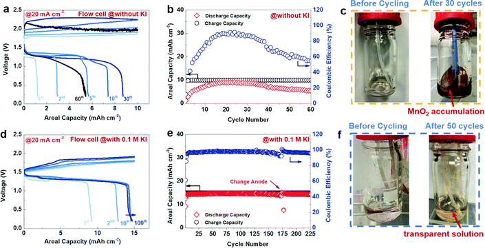 |
| | Fig. 13 The GCD performance of Zn/Mn RFB recorded at 20 mA cm−2 (a)–(c) without KI and (d)–(f) with 0.1 M KI (reproduced from ref. 82 with permission from The Royal Society of Chemistry). | |
Similarly, bromide ions have been adopted as an additive in aqueous electrolyte to realize high reversibility, two electron transfer between Mn2+ and MnO2, and complete dissolution of dead MnO2. The presence of the bromide-based additive effectively controls the dead MnO2 by chemical–electrochemical reaction. As a result, it widened the energy density and durability of aqueous manganese-based batteries.83,84 Yu et al.85 reported a highly reversible Zn/Mn RFB by introducing EDTA–Mn as the catholyte. The EDTA strongly coordinated to Mn2+ and as a result it enhances the electrochemical activity of the Mn2+/Mn3+ redox couple and effectively resists the Mn3+ disproportionation to solid MnO2. The EDTA–Mn employed catholyte exhibits a stable rate performance with a high CE of 95% at 10 to 50 mA cm−2. Moreover, the Zn/EDTA–Mn shows an excellent cyclability over 300 cycles and delivered a maximum CE of 98% and EE of 75% at 20 mA cm−2, respectively. Nana et al.86 synthesized highly crystalline spinel type λ-MnO2 and used it as a cathode for a Zn/λ-MnO2 RFB, as depicted in Fig. 14(a). The single flow Zn/λ-MnO2 RFB (Electrolyte: 1 M ZnSO4 in 1 M Li2SO4) displayed a discharge voltage of 1.5–2.1 V, which is higher than that of the conventional Zn/MnO2 battery. It delivered a maximum specific capacity of 129.8 mA h g−1 at 0.5C current rate, as shown in Fig. 14(b). Moreover, it exhibits 1000 cycles with 98.2% and 95.1% coulombic efficiency at 2C and 10C current rate, respectively. The two plateaus in the charge and discharge voltages are due to the occurrence of two oxidations and reductions corresponding to the insertion/extraction of Li+ ions into λ-MnO2 followed by Mn4+ to Mn3+/Mn2+ and Mn2+/Mn3+ to Mn4+, respectively. The single flow Zn/λ-MnO2 RFB at 2C rate shows an initial capacity of 128 mA h g−1, and retained the capacity up to 83% even after 1000 cycles at 10C rate exhibiting the excellent performance of the Zn/λ-MnO2 system, as shown in Fig. 14(c).
 |
| | Fig. 14 (a) Schematic illustration of the single flow Zn/λ-MnO2 RFB, (b) the GCD profile of single flow Zn/λ-MnO2 RFB at different C rates, and (c) long cycling performance of Zn/λ-MnO2 RFB recorded at 2 and 10C rates.86 | |
Interestingly, Li et al.87 constructed a membrane-free aqueous Zn/MnO2 RFB by using MnSO4 as the catholyte, ZnSO4 as the anolyte, carbon felt as the cathode, and zinc foil as the anode, as shown in Fig. 15(a)–(c). The fabricated membrane-free Zn/MnO2 RFB system displayed a high discharge voltage of 1.78 V with 100% capacity retention over 1000 cycles at 0.5 mA h cm−2 and approximately 95% over 500 cycles at 2 mA h cm−2. Moreover, the cell was charged to 1.2 A h and discharged at 500 mA current rate, but still it shows 1.1 A h of discharge capacity with 92% coulombic efficiency, as shown in Fig. 15(d). Fascinatingly, the Zn/MnO2 RFB shows excellent cyclability for about 500 cycles at 1000 mA current rate with 89.7% coulombic efficiency, as shown in Fig. 15(e). Surprisingly, the authors didn’t observe any passivation of zinc and MnO2 on the electrode, after the end of the cycling performance. This suggested the possibility to achieve high cyclability of this technology.
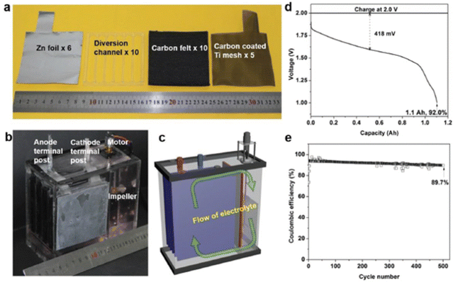 |
| | Fig. 15 (a) The cell components used for the membrane free aqueous Zn/MnO2 RFB, (b) photographic image of the Zn/MnO2 RFB, (c) schematic diagram of the indication of electrolyte flow, (d) the GCD profile of the Zn/MnO2 RFB, and (e) the cyclability of the Zn/MnO2 RFB (reproduced from ref. 87 with permission from Wiley). | |
Much attention has been dedicated to Mn2+/Mn3+ and Mn2+/MnO2 redox couples in redox flow batteries as a competitive contender for large-scale energy storage. With the aforementioned difficulties rectified, it may be ready for commercialization in the near future. However, we recognise that further sophisticated designs and tactics are required to turn this newly suggested manganese-based redox flow battery system into a commercially integrated technology.88,89
5. Challenges in manganese redox couples
Every manganese-based RFB has its own advantages with the remaining critical issues recorded in Fig. 16. Furthermore, manganese-based RFBs have more demanding criteria for the active species permeability and ion selectivity of the ion-exchange membrane since the electrolyte of manganese-based RFBs contains a range of metal ions.90 The expensive commercially available cation exchange membranes (such as Nafion membranes and perfluorosulfonic acid membrane) are a significant barrier to the scalability of manganese-based RFBs. Therefore, the development of low cost membranes with superior ion selectivity, mechanical strength, and chemical tolerance is of great importance.
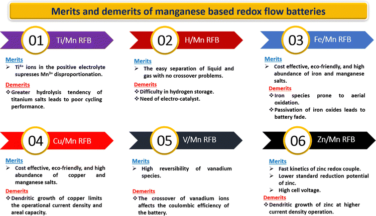 |
| | Fig. 16 Pictorial representation of the merits and demerits of manganese-based RFBs. | |
As dictated from the Frost diagram, Mn3+ ions are highly unstable in an aqueous medium and readily undergo a disproportionation reaction, which leads to the formation of the thermodynamically stable product MnO2. The formed MnO2 is insoluble in an aqueous medium and eventually gets deposited on the electrode surface. As a result, it gives rise to the following issues:
(i) Pressure drop
(ii) Passivation of MnO2 on the electrode surface
(iii) Flow field blocking for the incoming electrolyte
(iv) Decrease in the conductivity of the electrode
(v) Reduced mass transport
All of these listed issues hamper the battery performance severely, and therefore efforts have to be taken to overcome the critical issues by tuning the electrolytes, electrodes, and membranes, respectively.
6. Future perspectives and opportunities
To accelerate the development of redox couples in manganese-based flow batteries, researchers are actively concentrating and researching on improving the manganese redox couples. A schematic picture of the challenges and future goals is shown in Fig. 17.
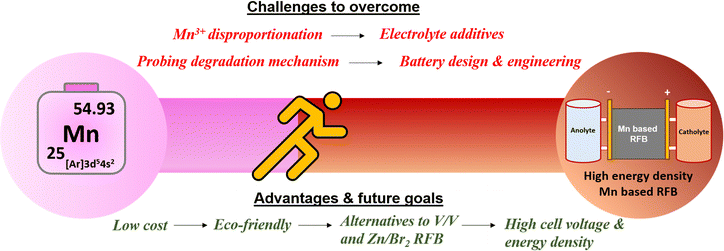 |
| | Fig. 17 Schematic illustration of the challenges and future goals in manganese-based redox flow batteries. | |
Selection of an appropriate negative redox couple is the most prominent area of research for high voltage and high performance devices enabling practical applications for sustainable large scale energy storage. The following section highlights the hidden opportunities in the manganese-based redox flow batteries.
I. Improving the conductivity of the positive electrode by adopting a suitable conductive agent, enhancing significantly the electrochemical performance of manganese.
II. Development of a novel complexing agent is needed to stabilize the Mn3+ ions during battery use.
III. Development of novel electrolyte additives to suppress the particle size of MnO2 for achieving maximum energy density.
IV. Plentiful opportunities in tailoring organic molecules as a negative redox species when combined with the manganese redox couple, which is expected to offer high cell voltage, high energy density and high cyclability.
V. To gain fundamental insights into the fundamental working principles of Mn2+/Mn3+ redox reactions and the tendency of Mn3+ disproportionation reaction employing effective simulation and theoretical calculations.
VI. The development of a unique battery design and engineering (flow field design and battery architecture) helps researchers to attain enhanced performance.
VII. It is essential to deepen our understanding of ion transport in manganese-based RFBs using computational approaches and to carry out more proficient and extensive membrane design and characterization in order to achieve better membranes.
VIII. Employ in situ and ex situ advanced characterization techniques to understand the limited cycle life and failure mechanism.
IX. Methodical post-diagnostic analysis of the electrodes and electrolytes.
The successful incorporation of the manganese redox couple in the field of redox flow batteries has been growing rapidly. As mentioned earlier, the manganese redox couple has many salient features which would be useful for successful commercialization. We strongly believe that manganese-based RFBs have gained significant attention for futuristic scalable energy storage applications.
7. Conclusion
To summarize, constructing an efficient redox flow battery is urgently required to solve the energy storage demand for sustainable energy storage, globally. The redox couples play a key role in determining the energy density of the battery. Recently, the manganese (Mn2+/Mn3+) redox couple has gained attention due to its cost effectiveness, eco-friendliness, high abundance, and high standard reduction potential (1.51 V vs. SHE). However, the manganese redox couple possesses intrinsic issues discussed in this review that need to be addressed. This review highlights the recent developments in the manganese-based redox couples for redox flow batteries and their results are elaborately discussed. Though many reports are reported so far, every system has its own challenges to solve. Thus, exhaustive research is urgently required to improve the overall flow cell battery performance.
Conflicts of interest
The authors declare no conflict of interest.
Acknowledgements
Dr P. Ragupathy would like to acknowledge CSIR, New Delhi for the financial support through Focused Basic Research (FBR), project number: MLP-0322 and awarding Raman Research Fellowship. He also thanks Davidson School of Chemical Engineering, Purdue University, IN, USA for hosting The Raman Fellow. Prof. Pol is deeply thankful to Purdue University, IN, USA for the sabbatical break for the year 2023, which allowed the methodical materialization of this review.
References
- J. M. Tarascon, ChemSusChem, 2008, 1, 777–779 CrossRef CAS PubMed.
- P. Leung, X. Li, P. De Leo, L. Berlouis, C. T. John and F. C. Walsh, RSC Adv., 2012, 2, 10125–10156 RSC.
- L. Zhang, H. Zhang, Q. Lai, X. Li and Y. Cheng, J. Power Sources, 2013, 227, 41–47 CrossRef CAS.
- T. Shigematsu, Arab. J. Sci. Eng., 2013, 38, 723–739 CrossRef.
- S. P. S. Badwal, S. S. Giddey, C. Munnings, A. I. Bhatt and A. F. Hollenkamp, Front. Chem., 2014, 2, 1–28 CAS.
- Z. Yang, J. Zhang, M. C. W. Kintner-Meyer, X. Lu, D. Choi, J. P. Lemmon and J. Liu, Chem. Rev., 2011, 111, 3577–3613 CrossRef CAS.
- J. B. Goodenough and K. S. Park, J. Am. Chem. Soc., 2013, 135, 1167–1176 CrossRef CAS PubMed.
- G. J. May, A. Davidson and B. Monahov, J. Energy Storage, 2018, 15, 145–157 CrossRef.
- A. Chad and J. Gza, IEEE Trans. Ind. Appl., 2007, 43, 769–776 Search PubMed.
- A. Manthiram, Y. Fu and Y. S. Su, J. Phys. Chem. Lett., 2013, 4, 1295–1297 CrossRef CAS PubMed.
- F. I. Materials, ACS Appl. Mater. Interfaces, 2018, 10, 22381–22388 CrossRef PubMed.
- M. L. Perry and A. Z. Weber, J. Electrochem. Soc., 2016, 163, A5064–A5067 CrossRef CAS.
- M. Bartolozzi, J. Power Sources, 1989, 27, 219–234 CrossRef CAS.
- J. Noack, N. Roznyatovskaya, T. Herr and P. Fischer, Angew. Chem., Int. Ed., 2015, 54, 9776–9809 CrossRef CAS PubMed.
- R. Pandiyan Naresh, K. Mariyappan, K. Selvakumar Archana, S. Suresh, D. Ditty, M. Ulaganathan and P. Ragupathy, ChemElectroChem, 2019, 6, 5688–5697 CrossRef CAS.
-
G. P. R. A. M. Vassallo, The Zinc/Bromine Flow Battery Materials Challenges and Practical Solutions for Technology Advancement, 2016 Search PubMed.
- M. Ulaganathan, V. Aravindan, Q. Yan, S. Madhavi, M. Skyllas-Kazacos and T. M. Lim, Adv. Mater. Interfaces, 2016, 3, 1–22 Search PubMed.
- P. Leung, X. Li, C. Ponce De León, L. Berlouis, C. T. J. Low and F. C. Walsh, RSC Adv., 2012, 2, 10125–10156 RSC.
- M. Ulaganathan, S. Suresh, K. Mariyappan, P. Periasamy and R. Pitchai, ACS Sustainable Chem. Eng., 2019, 7, 6053–6060 CrossRef CAS.
- Z. Li, G. Weng, Q. Zou, G. Cong and Y. C. Lu, Nano Energy, 2016, 30, 283–292 CrossRef CAS.
- B. S. Jayathilake, E. J. Plichta, M. A. Hendrickson and S. R. Narayanan, J. Electrochem. Soc., 2018, 165, A1630–A1638 CrossRef CAS.
- H. Zhang and C. Sun, J. Power Sources, 2021, 493, 229445 CrossRef CAS.
- B. S. Jayathilake, E. J. Plichta, M. A. Hendrickson and S. R. Narayanan, J. Electrochem. Soc., 2018, 165, A1630 CrossRef CAS.
- K. Zhang, X. Han, Z. Hu, X. Zhang, Z. Tao and J. Chen, Chem. Soc. Rev., 2015, 44, 699–728 RSC.
- W. Wei, X. Cui, W. Chen and D. G. Ivey, Chem. Soc. Rev., 2011, 40, 1697–1721 RSC.
- G. Fang, J. Zhou, A. Pan and S. Liang, ACS Energy Lett., 2018, 3, 2480–2501 CrossRef CAS.
- A. M. Kannan, S. Bhavaraju, F. Prado, M. M. Raja and A. Manthiram, J. Electrochem. Soc., 2002, 149, A483 CrossRef CAS.
- M. H. Alfaruqi, J. Gim, S. Kim, J. Song, J. Jo, S. Kim, V. Mathew and J. Kim, J. Power Sources, 2015, 288, 320–327 CrossRef CAS.
- H. Pan, Y. Shao, P. Yan, Y. Cheng, K. S. Han, Z. Nie, C. Wang, J. Yang, X. Li, P. Bhattacharya, K. T. Mueller and J. Liu, Nat. Energy, 2016, 1, 16039 CrossRef CAS.
- H. Tang, Y. Yin, Y. Huang, J. Wang, L. Liu, Z. Qu, H. Zhang, Y. Li, M. Zhu and O. G. Schmidt, ACS Energy Lett., 2021, 6, 1859–1868 CrossRef CAS.
- X. Yu, X. Wu, Y. Liang, K. Liang, S. Huang, K. Li, M. Chen, S. Liu, N. Li and Z. Shi, Batteries Supercaps, 2021, 4, 1201–1220 CrossRef CAS.
- C. J. Clarke, G. J. Browning and S. W. Donne, Electrochim. Acta, 2006, 51, 5773–5784 CrossRef CAS.
- J. Huang, L. Yan, D. Bin, X. Dong, Y. Wang and Y. Xia, J. Mater. Chem. A, 2020, 8, 5959–5967 RSC.
- C. Xie, T. Li, C. Deng, Y. Song, H. Zhang and X. Li, Energy Environ. Sci., 2020, 13, 135–143 RSC.
- D. Chao, C. Ye, F. Xie, W. Zhou, Q. Zhang, Q. Gu, K. Davey, L. Gu and S.-Z. Qiao, Adv. Mater., 2020, 32, 2001894 CrossRef CAS PubMed.
- D. Chao, W. Zhou, C. Ye, Q. Zhang, Y. Chen, L. Gu, K. Davey and S.-Z. Qiao, Angew. Chem., Int. Ed., 2019, 58, 7823–7828 CrossRef CAS PubMed.
- W. Chen, G. Li, A. Pei, Y. Li, L. Liao, H. Wang, J. Wan, Z. Liang, G. Chen, H. Zhang, J. Wang and Y. Cui, Nat. Energy, 2018, 3, 428–435 CrossRef CAS.
- M. Nan, M. Wu, Y. Liu, L. Qiao, H. Zhang and X. Ma, Small Methods, 2023, 7, 2201266 CrossRef CAS PubMed.
- Y. Liu, M. Nan, Z. Zhao, B. Shen, L. Qiao, H. Zhang and X. Ma, Chem. Eng. J., 2023, 465, 142602 CrossRef CAS.
- X. Ye, D. Han, G. Jiang, C. Cui, Y. Guo, Y. Wang, Z. Zhang, Z. Weng and Q.-H. Yang, Energy Environ. Sci., 2023, 16, 1016–1023 RSC.
- J. Lei, Y. Yao, Y. Huang and Y.-C. Lu, ACS Energy Lett., 2023, 8, 429–435 CrossRef CAS.
- F. Q. Xue, Y. L. Wang, W. H. Wang and X. D. Wang, Electrochim. Acta, 2008, 53, 6636–6642 CrossRef CAS.
- X. Li, Y. Tang, C. Han, Z. Wei, H. Fan, H. Lv, T. Cai, Y. Cui, W. Xing, Z. Yan, C. Zhi and H. Li, ACS Nano, 2023, 17, 5083–5094 CrossRef CAS PubMed.
- E. C. S. Transactions, ECS Trans., 2015, 69, 59–67 Search PubMed.
- L. Qiao, C. Xie, M. Nan, H. Zhang, X. Ma and X. Li, J. Mater. Chem. A, 2021, 9, 12606–12611 RSC.
- M. Nan, L. Qiao, Y. Liu, H. Zhang and X. Ma, J. Power Sources, 2022, 522, 230995 CrossRef CAS.
- W. A. Braff, M. Z. Bazant and C. R. Buie, Nat. Commun., 2013, 4, 2346 CrossRef PubMed.
- K. Saadi, P. Nanikashvili, Z. Tatus-Portnoy, S. Hardisty, V. Shokhen, M. Zysler and D. Zitoun, J. Power Sources, 2019, 422, 84–91 CrossRef CAS.
- M. Küttinger, R. Brunetaud, J. K. Włodarczyk, P. Fischer and J. Tübke, J. Power Sources, 2021, 495, 229820 CrossRef.
- K. Saadi, M. Kuettinger, P. Fischer and D. Zitoun, Energy Technol., 2021, 9, 2000978 CrossRef CAS.
- M. Küttinger, P. A. Loichet Torres, E. Meyer and P. Fischer, Chem. – Eur. J., 2022, 28, e202103491 CrossRef PubMed.
- S. S. Hardisty, K. Saadi, S. Nagaprasad Reddy, I. Grinberg and D. Zitoun, Mater. Today Energy, 2022, 24, 100937 CrossRef CAS.
- A. Modestov, N. Kartashova, R. Pichugov, M. Petrov, A. Antipov and L. Abunaeva, Membranes, 2022, 12(8), 815 CrossRef CAS PubMed.
- H. Hewa Dewage, B. Wu, A. Tsoi, V. Yufit, G. Offer and N. Brandon, J. Mater. Chem. A, 2015, 3, 9446–9450 RSC.
- J. Rubio-garcia, A. Kucernak, D. Zhao, D. Li, K. Fahy and V. Yu, J. Phys. Energy, 2018, 1, 015006 CrossRef.
- C. Sun and H. Zhang, ChemSusChem, 2022, 15, e202101798 CrossRef CAS PubMed.
- H. Chen, X. Zhang, S. Zhang, S. Wu, F. Chen and J. Xu, Chem. Eng. J., 2022, 429, 132403 CrossRef CAS.
- Y. K. Zeng, T. S. Zhao, X. L. Zhou, L. Wei and H. R. Jiang, J. Power Sources, 2016, 330, 55–60 CrossRef CAS.
- Y. K. Zeng, T. S. Zhao, X. L. Zhou, L. Wei and Y. X. Ren, J. Power Sources, 2017, 346, 97–102 CrossRef CAS.
- K. Gong, F. Xu, J. B. Grunewald, X. Ma, Y. Zhao, S. Gu and Y. Yan, ACS Energy Lett., 2016, 1, 89–93 CrossRef CAS.
- C. Xie, Y. Duan, W. Xu, H. Zhang and X. Li, Angew. Chem., Int. Ed., 2017, 56, 14953–14957 CrossRef CAS PubMed.
- S. Selverston, R. F. Savinell and J. S. Wainright, J. Electrochem. Soc., 2017, 164, A1069 CrossRef CAS.
- K. S. Archana, S. Suresh and P. Ragupathy, Electrochim. Acta, 2020, 345, 136245 CrossRef CAS.
- J. Wu, J. Yang, Z. Y. Leong, F. Zhang, H. Deng, G. F. Ouyang and J. Yu, ACS Appl. Energy Mater., 2022, 5, 14646–14651 CrossRef CAS.
- D. Lloyd, E. Magdalena, L. Sanz, L. Murtomäki and K. Kontturi, J. Power Sources, 2015, 292, 87–94 CrossRef CAS.
- D. Lloyd, T. Vainikka and K. Kontturi, Electrochim. Acta, 2013, 100, 18–23 CrossRef CAS.
- L. Sanz, D. Lloyd, E. Magdalena, J. Palma, M. Anderson and K. Kontturi, J. Power Sources, 2015, 278, 175–182 CrossRef CAS.
- L. Wei, L. Zeng, M. C. Wu, H. R. Jiang and T. S. Zhao, J. Power Sources, 2019, 423, 203–210 CrossRef CAS.
- L. Wei, L. Zeng, M. C. Wu, H. R. Jiang and T. S. Zhao, J. Power Sources, 2019, 423, 203–210 CrossRef CAS.
- T. Hong and F. Xue, Power Energy Eng. Conf, 2009 DOI:10.1109/APPEEC.2009.4918453.
- H. J. Lee, S. Park and H. Kim, J. Electrochem. Soc., 2018, 165, A952–A956 CrossRef CAS.
- S. Park, H. Lee, H. J. Lee and H. Kim, J. Power Sources, 2020, 451, 1–6 CrossRef.
- M. A. Rodrigues, A. C. Catto, E. Longo, E. Nossol and R. C. Lima, J. Rare Earths, 2018, 36, 1074–1083 CrossRef CAS.
- D. Reynard, S. Maye, P. Peljo, V. Chanda, H. H. Girault and S. Gentil, Chem. – Eur. J., 2020, 26, 7250–7257 CrossRef CAS PubMed.
- M. Chem, Mater. Chem. Front., 2021, 5, 2201–2217 RSC.
- Y. Zuo, K. Wang, P. Pei, M. Wei, X. Liu, Y. Xiao and P. Zhang, Mater. Today Energy, 2021, 20, 100692 CrossRef CAS.
- X. Xie, F. Mushtaq, Q. Wang and W. A. Daoud, ACS Energy Lett., 2022, 7, 3484–3491 CrossRef CAS.
- M. C. Wu, T. S. Zhao, H. R. Jiang, Y. K. Zeng and Y. X. Ren, J. Power Sources, 2017, 355, 62–68 CrossRef CAS.
- B. Li, Z. Nie, M. Vijayakumar, G. Li, J. Liu, V. Sprenkle and W. Wang, Nat. Commun., 2015, 6, 1–8 Search PubMed.
- Z. Zhang, D. Zhou, Z. Xie, X. Bao, B. Wu, Z. Liu and B. Huang, Mater. Chem. Phys., 2019, 228, 75–79 CrossRef CAS.
- R. Pandiyan Naresh, K. Mariyappan, D. Dixon, M. Ulaganathan and P. Ragupathy, Batteries Supercaps, 2021, 4, 1464–1472 CrossRef.
- J. Lei, Y. Yao, Z. Wang and Y.-C. Lu, Energy Environ. Sci., 2021, 14, 4418–4426 RSC.
- J. Wu, Y. Li, J. Huang, X. Chi, J. Yang and Y. Liu, J.
Mater. Chem. A, 2021, 9, 21888–21896 RSC.
- Y. Liu, C. Xie and X. Li, Angew. Chem., Int. Ed., 2022, 1–8 Search PubMed.
- X. Yu, Y. Song and A. Tang, J. Power Sources, 2021, 507, 230295 CrossRef CAS.
- N. Liu, K. Mohanapriya, J. Pan, Y. Hu, Y. Sun and X. Liu, J. Electrochem. Soc., 2020, 167, 040517 CrossRef CAS.
- G. Li, W. Chen, H. Zhang, Y. Gong, F. Shi, J. Wang, R. Zhang, G. Chen, Y. Jin, T. Wu, Z. Tang and Y. Cui, Adv. Energy Mater., 2020, 10, 1–10 Search PubMed.
- Z. Liu, L. Qin, B. Lu, X. Wu, S. Liang and J. Zhou, ChemSusChem, 2022, 15, e202200348 CAS.
- M. Wang, X. Zheng, X. Zhang, D. Chao, S.-Z. Qiao, H. N. Alshareef, Y. Cui and W. Chen, Adv. Energy Mater., 2021, 11, 2002904 CrossRef CAS.
- H. Zhang and C. Sun, J. Power Sources, 2021, 493, 229445 CrossRef CAS.
|
| This journal is © The Royal Society of Chemistry 2023 |
 Open Access Article
 *c and
P.
Ragupathy
 *abc
*abc


