
Systematic investigation via controlling the energy gap of the local and charge-transfer triplet state for enabling high efficiency thermally activated delayed fluorescence emitters†
Nisha
Yadav
 ,
Upasana
Deori
,
Ezhakudiyan
Ravindran
,
Bahadur
Sk
and
Pachaiyappan
Rajamalli
*
,
Upasana
Deori
,
Ezhakudiyan
Ravindran
,
Bahadur
Sk
and
Pachaiyappan
Rajamalli
*
Materials Research Centre, Indian Institute of Science Bangalore, C. V. Raman Road, Bengaluru, Karnataka 560012, India. E-mail: rajamalli@iisc.ac.in
First published on 6th November 2023
Abstract
Thermally activated delayed fluorescence (TADF) emitters have evolved as a certified candidate in light generation technologies for producing efficient organic light-emitting diodes (OLEDs) on account of their 100% internal quantum efficiency (IQE) via reverse intersystem crossing (RISC) and toxic metal-free design. The fast rate of RISC (kRISC) is the ultimate requirement of an efficient TADF emitter, which can be achieved by minimizing the singlet–triplet energy gap (ΔEST). Here, four donor–acceptor type TADF emitters namely 3BPy-mDCz, 3BPy-mDTA, 3BPy-mDMAC, and 3BPy-mDPT were synthesized based on benzoyl pyridine (3BPy) as an unaltered acceptor and varying the donor strength ranging from carbazole to phenothiazine. These emitters show low ΔEST values forecasting their TADF nature. The ΔEST values decreased from 0.22 to 0.14 eV upon increasing the donor strength. The maximum external quantum efficiency (EQE) of 18.7% for 3BPy-mDCz, 22.5% for 3BPy-mDTA, 13.8% for 3BPy-mDMAC and 2.1% for 3BPy-mDPT was obtained. These drastic differences in the performances of 3BPy-mDTA and 3BPy-mDPT are due to the locally excited 3LE(T2) intermediate state between the lowest singlet (S1) and triplet (T1). Among 3BPy-mDMAC and 3BPy-mDPT, the efficiency of 3BPy-mDMAC is superior due to less CT character and high photoluminescence quantum yield (PLQY). This work paves a new direction for efficient TADF molecular design by indicating the role of the intermediate triplet state (3LE) despite possessing high ΔEST values.
1. Introduction
Light-emitting materials with thermally activated delayed fluorescence (TADF) have attracted a great deal of interest owing to the utilization of their potential features in next-generation organic light-emitting diodes (OLEDs).1,2 TADF emitters have emerged as a promising technology and prospective alternative to phosphorescent emitters for OLEDs due to their ability to reach 100% internal quantum efficiency (IQE) without the use of rare-earth metals.3–8 Efficient up-conversion via reverse intersystem crossing (RISC) is needed in TADF emitters to achieve a reduction in triplet–triplet annihilation (TTA), which is the primary cause of degradation in phosphorescent emitters.9,10 Hence, fast RISC is required to acquire high-performance TADF OLEDs over phosphorescent OLEDs. Therefore, a small energy gap between the lowest singlet (S1) and triplet (T1) excited states (ΔEST < 0.2 eV) is required to facilitate efficient exciton up-conversion from T1 → S1via reverse intersystem crossing.11,12 A commonly used TADF molecular design strategy is constructing a twisted molecular conformation with various donor and acceptor units in order to separate the highest occupied molecular orbital (HOMO) and lowest unoccupied molecular orbital (LUMO) and achieve small ΔEST.13–15 Furthermore, increasing the steric hindrance and highly twisted conformation and breaking conjugation in the molecular geometry are also the most effective pathways to fulfill the above criterion via minimizing electron exchange energy splitting S1 from T1.16–19According to the Franck–Condon transition principle and Fermi's golden rule, high oscillator strength is needed for high photoluminescence quantum yield (ΦPL), which can be achieved by a large overlap degree of the frontier molecular orbital.2,18,20 Upon increasing the donor strength we can get low ΔEST but it suffers from low ΦPL due to which efficient TADF can’t be obtained. The main reason behind this is the weak spin–orbit coupling (SOC) between S1 and T1 due to the charge transfer (CT) character of states leading to inefficient RISC.21–23 Hence, low ΔEST is not the sole criteria to achieve efficient TADF emitters. There are several requirements for efficient TADF materials but the core parameter is still the fast rate of RISC (kRISC) as well as radiative de-activation (kr). For efficient TADF, both small ΔEST and considerable kRISC have to be realized simultaneously.
SOC in purely organic emitters has drawn considerable attention due to its tendency to facilitate RISC. According to the El-Sayed rule, SOC increases with the difference in nature of the excited states (charge transfer excited state, CT vs. localized excited state, LE).24 In most of the cases, S1 displays predominantly CT character (1CT) and therefore the vicinity of the localized triplet state (3LE) will increase SOC.25,26 RISC proceeds via vibronic coupling between 3CT(T1) and 3LE(T2) states followed by SOC between 1CT(S1) and 3LE(T2).23,27,28 Although there are a range of theoretical reports explaining the role of intermediate states in enhancing SOC, it is less explored experimentally in purely organic emitters without any heavy atom. To overcome this bottleneck, the optimum molecular design for efficient TADF emitters should be well understood and proper guidelines for rational molecular design are highly desired for the practical application of TADF-based OLEDs.
In this study, we designed and synthesized four donor–acceptor based TADF molecules 3BPy-mDCz, 3BPy-mDTA, 3BPy-mDMAC and 3BPy-mDPT (Scheme 1). Benzoyl pyridine (3BPy) acts as an unaltered acceptor moiety while the donor moiety varies from carbazole to phenothiazine. The ΔEST values also decreased from 0.22 to 0.14 eV, and hence improved performance was expected. By adopting the above emitters as dopants, we acquire blue to yellow TADF OLEDs. However, the maximum EQEs of 18.7% for 3BPy-mDCz, 22.5% for 3BPy-mDTA, 13.8% for 3BPy-mDMAC and 2.1% for 3BPy-mDPT were obtained. 3BPy-mDCz and 3BPy-mDTA possess an intermediate 3LE(T2) state between S1 and T1 which facilitates both kRISC and kr and hence these emitters show high efficiency as compared to other emitters. High performance can be achieved in spite of having a relatively large ΔEST value via systematically optimising the number and nature of intermediate states between S1 and T1. This work highlights that increasing the donor strength or reducing the ΔEST is not the only desired criteria to get efficient TADF while the position/nature of the additional triplet state (3LE/3CT) state is equally important in enhancing the efficiency of TADF emitters.29,30
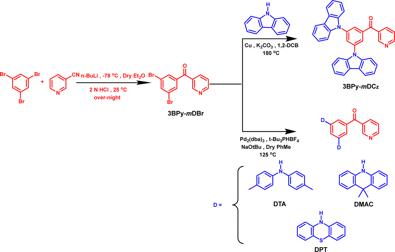 | ||
| Scheme 1 Synthesis of 3BPy-mDCz, 3BPy-mDTA, 3BPy-mDMAC and 3BPy-mDPT. | ||
2. Results and discussion
2.1. Theoretical calculation
To understand the effect of variation of the donor moieties, density functional theory (DFT) and time-dependent DFT (TD-DFT) calculations were performed using the B3LYP/6-31G(d,p) method. The atomic delocalization of the S0 geometry and excited-state energy levels of the four designed molecules was then conducted. Fig. 1 shows the optimized molecular structure along with the molecular orbital distribution of the HOMO and the LUMO of these molecules. The LUMOs were mainly residing on the acceptor unit (3BPy) due to its electron withdrawing nature while the HOMOs were widely localized on the donor groups and extended to the phenyl ring based on their descending order of donor strengths, which are crucial for the occurrence of delayed fluorescence. The calculated excitation energies and HOMO/LUMO energy levels of the S1 and T1 excited states are shown in Table S1, ESI.† The FMO distributions resulted in reduced ΔEST values as 0.19, 0.24, 0.03 and 0.02 eV for 3BPy-mDCz, 3BPy-mDTA, 3BPy-mDMAC and 3BPy-mDPT, respectively. The small ΔEST values suggest that molecules can exhibit TADF properties. Overlap between the HOMO and LUMO retains high oscillator strength (f) in 3BPy-mDCz and 3BPy-mDTA as compared to other derivatives, which is helpful to maintain a high radiative decay rate (kr).31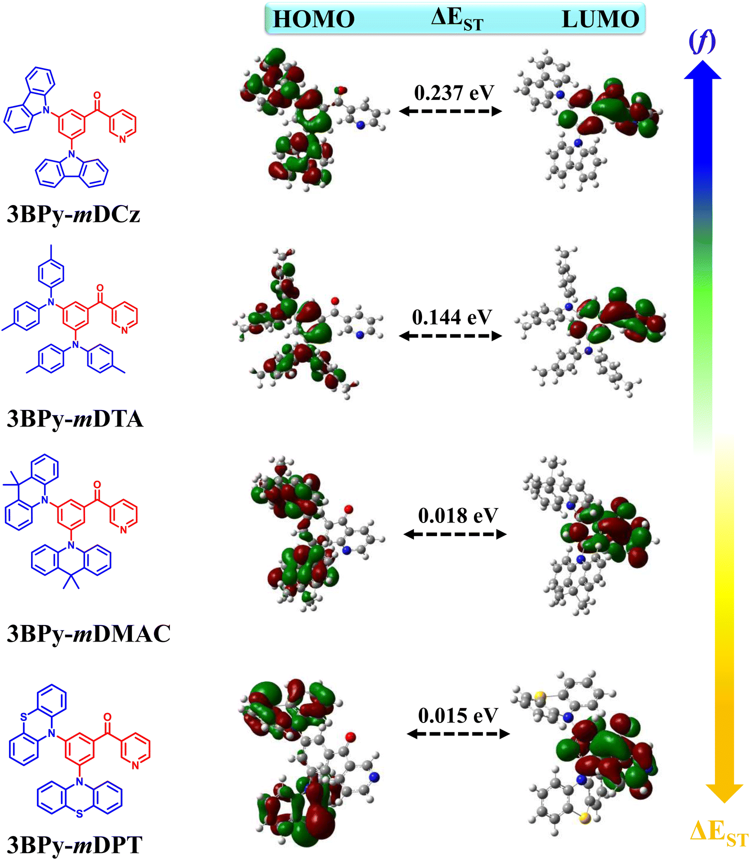 | ||
| Fig. 1 The distribution of the molecular orbital of the HOMO and LUMO with a calculated S1 and T1 energy gap (ΔEST). The right side top and bottom of the arrow marks indicate the enhancement of oscillator strengths (f) and reduction of ΔEST when increasing the donor strength. | ||
2.2. Synthesis and characterization
The designed compounds were synthesized in high yields via the Ullmann coupling reaction and Buchwald–Hartwig amination of (3-bromobenzoyl)pyridine with various donor moieties. The synthetic routes are displayed in Scheme 1 while the detailed synthetic procedures and characterization data are given in the ESI.† All the compounds were further purified by temperature-gradient vacuum sublimation and chemical structures are confirmed by 1H, 13C NMR and high-resolution mass spectrometry (HRMS) (Fig. S9–S18, ESI†).2.3. Thermal and electrochemical properties
All four materials (3BPy-mDCz, 3BPy-mDTA, 3BPy-mDMAC and 3BPy-mDPT) show good thermal stability with decomposition temperatures (Td) corresponding to 5 wt% loss in the range of 331–422 °C (Fig. S1, ESI† and Table 1). The glass transition was not obtained during differential scanning calorimetry (DSC) analysis. These high stabilities are important for stable film formation.| Compound | λ abs (nm) | λ PL (nm) (sol/film) | λ Ph (nm) (sol/film) | ΔESTd (eV) (sol/film) | ϕ PL (air/vac) | τ P (ns) | τ D (μs) (air/vac) | T d (°C) |
|---|---|---|---|---|---|---|---|---|
| a Absorbance peaks. b Steady state emission maxima at room temperature. c Phosphorescence emission maxima in solution measured in toluene (Tol) (1 × 10⁻⁵ M) and doped film (7 wt% of emitter:host) at 77 K. d Singlet–triplet energy gap. e Absolute PLQY in doped films using an integrating sphere under air and vacuum atmosphere. f Prompt lifetime. g Delayed lifetime at room temperature under air and vacuum. h Thermal decomposition temperature under a N2 atmosphere. | ||||||||
| 3BPy-mDCz | 338, 372 | 456/463 | 472/493 | 0.13/0.22 | 56/59 | 10.3 | 118.8/340.3 | 381 |
| 3BPy-mDTA | 300, 424 | 522/532 | 551/576 | 0.18/0.20 | 16/48 | 6.8 | 119.7/785.7 | 350 |
| 3BPy-mDMAC | 287, 401 | 534/528 | 547/535 | 0.15/0.11 | 34/53 | 30.9 | 6.6/9.2 | 331 |
| 3BPy-mDPT | 319, 425 | —/551 | —/565 | —/0.14 | 7/12 | 16.1 | 13.8/41.4 | 422 |
The energy band gap (Eg) that is being calculated from the absorption onset for all emitters is listed in Table S2, ESI.† The electrochemical properties of all the four emitters were examined by cyclic voltammetry (CV) as shown in Fig. S2, ESI.†![[thin space (1/6-em)]](https://www.rsc.org/images/entities/char_2009.gif) 32 All emitters exhibited two reversible oxidation waves confirming the oxidation of both the donor moieties. The HOMO energy level came out to be −5.26, −5.14, −4.95 and −5.03 eV for 3BPy-mDCz, 3BPy-mDTA, 3BPy-mDMAC and 3BPy-mDPT, respectively, as listed in Table S2, ESI.† Upon increasing the donor strength, the HOMO level increases due to the increase in the electron donating ability and this trend matches with theoretical values. The calculated LUMO energy levels were −2.26, −2.54, −2.25 and −2.65 eV, respectively, by taking into account the HOMO and Eg values.
32 All emitters exhibited two reversible oxidation waves confirming the oxidation of both the donor moieties. The HOMO energy level came out to be −5.26, −5.14, −4.95 and −5.03 eV for 3BPy-mDCz, 3BPy-mDTA, 3BPy-mDMAC and 3BPy-mDPT, respectively, as listed in Table S2, ESI.† Upon increasing the donor strength, the HOMO level increases due to the increase in the electron donating ability and this trend matches with theoretical values. The calculated LUMO energy levels were −2.26, −2.54, −2.25 and −2.65 eV, respectively, by taking into account the HOMO and Eg values.
2.4. Photophysical properties
Photophysical properties of 3BPy-mDCz, 3BPy-mDTA, 3BPy-mDMAC and 3BPy-mDPT in 10 μM toluene solution are shown in Fig. 2 and Fig. S3, ESI.† All the compounds display similar absorption spectral profiles with a strong absorption band observed before 350 nm associated with the π–π and n–π* transitions33 and relatively weak and structureless broadband absorption peaks observed at 372, 425, 394 and 423 nm for 3BPy-mDCz, 3BPy-mDTA, 3BPy-mDMAC and 3BPy-mDPT, respectively, which is associated with the intramolecular charge transfer (ICT) from the donor moieties to the acceptor moiety.34 The PL spectra were measured in toluene (10 μM) at room temperature (RT) and 3BPy-mDCz, 3BPy-mDTA and 3BPy-mDMAC show slightly broad and structureless emission. 3BPy-mDPT is not emissive in the solution state, and hence the emission spectra couldn’t be studied in the solution state. The summary of the photophysical properties is depicted in Table 1. It is noteworthy that the emission maximum peaks of 3BPy-mDCz, 3BPy-mDTA and 3BPy-mDMAC have been observed at 456, 522 and 534 nm, respectively. Furthermore, the S1 energies were calculated to be 3.08, 2.71 and 2.76 eV, respectively from the onset of the fluorescence spectra. The phosphorescence spectra of these systems were measured at 77 K in toluene (10 μM) with peaks centered at 472, 551 and 547 nm, respectively, as shown in Fig. 2. The phosphorescence spectra of these emitters showed broad structureless emission, which indicates that their phosphorescence emission originates from the CT triplet state of these molecules. Furthermore, the T1 energies were calculated to be 2.95, 2.53 and 2.61 eV, respectively from the onset of their phosphorescence spectra. Therefore, the ΔEST was estimated in the range of 0.13, 0.18 and 0.15 eV, respectively, as shown in Table 1. The small ΔEST of these molecules suggests that these emitters may have TADF properties. The solvatochromic study was done by taking emission spectra in various solvent polarities as shown in Fig. S4, ESI.† Significantly, their PL spectra are concomitantly red-shifted and slightly broadened with the increase of the solvent polarity, which clearly indicates that these molecules are CT in nature and the S1 state is stabilized upon increasing solvent polarity.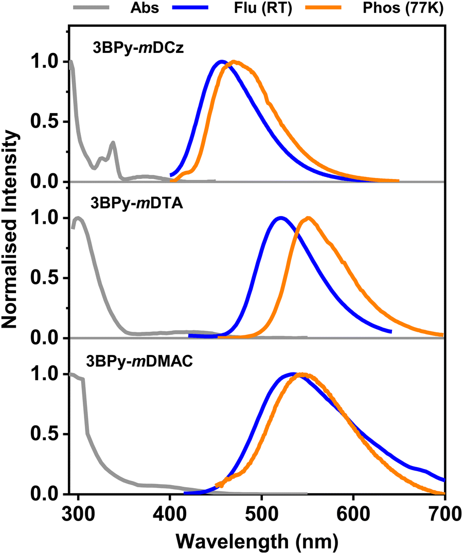 | ||
| Fig. 2 UV-Vis absorption, fluorescence (RT), and phosphorescence (77 K) spectra of 3BPy-mDCz, 3BPy-mDTA, and 3BPy-mDMAC respectively in toluene (Tol) (1 × 10⁻⁵ M). | ||
In order to get an overview of the optical properties in the thin film, a photophysical study was carried out in doped thin film. DPEPO (triplet energy of 3.0 eV) host was taken for 3BPy-mDCz while mCBP (triplet energy of 2.8 eV) host was taken for the remaining three emitters, which confine triplet excitons and efficiently suppress backward energy transfer from the guest to the host materials. The doped films with 7 wt% doping concentration give blue to yellow emission with an emission peak of 463 nm for 3BPy-mDCz, 532 nm for 3BPy-mDTA, 528 nm for 3BPy-mDMAC and 551 nm for 3BPy-mDPT. The fluorescence and phosphorescence spectra of the co-doped films were measured and presented in Fig. 3 and Table 1. The ΔEST values measured from the onset of the PL spectra at RT and phosphorescence spectra at 77 K are 0.22, 0.20, 0.11 and 0.14 eV for 3BPy-mDCz, 3BPy-mDTA, 3BPy-mDMAC and 3BPy-mDPT, respectively. The ΔEST gradually decreased upon increasing the donor strength. These values are low enough to have efficient up-conversion of T1 excitons to the S1 state.35
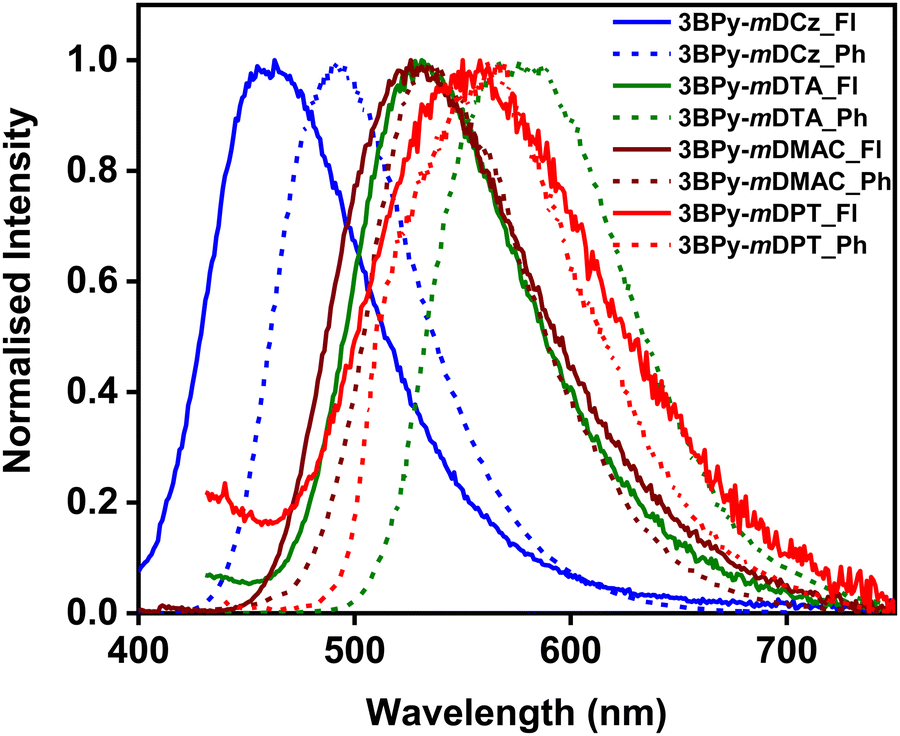 | ||
| Fig. 3 Fluorescence (Fl) and phosphorescence (Ph) spectra of 7 wt% 3BPy-mDCz:DPEPO, 3BPy-mDTA:mCBP, 3BPy-mDMAC:mCBP and 3BPy-mDPT:mCBP doped film. | ||
Furthermore, the PLQY of the doped films was measured using an integrating sphere under the air and a N2 atmosphere. Under air, the PLQYs of the doped films came out to be 56% for 3BPy-mDCz, 16% for 3BPy-mDTA, 34% for 3BPy-mDMAC and 7% for 3BPy-mDPT while under a N2 atmosphere, the PLQY increased to 59% for 3BPy-mDCz, 48% for 3BPy-mDTA, 53% for 3BPy-mDMAC and 12% for 3BPy-mDPT. The PLQY enhancement in a N2 atmosphere compared to air is likely due to the suppression of triplet exciton quenching by atmospheric oxygen.36,37 The corresponding PLQY values decreased as the donor strength increased on account of the increase in CT character.22 The decrease of PLQY in the presence of oxygen supports that these materials possess unambiguous TADF properties and suggests that the T1 states of these molecules are readily quenched by the triplet ground state oxygen molecules. The quenching of T1 by oxygen leads to the quenching of the delayed fluorescence and a decrease in the emission intensity.
To further reveal the effect of donor strength on the TADF properties of the emitters, we studied transient photoluminescence decay (TRPL) of the doped films (7 wt% 3BPy-mDCz, 3BPy-mDTA, 3BPy-mDMAC and 3BPy-mDPT) which were fabricated by vacuum deposition. As shown in Fig. 4, the transient decay curves show two components. The first one is the prompt fluorescence decay from S1 to S0 with a lifetime τP and the second one is delayed emission with a lifetime τd, which can be rationalized as the thermal up-conversion of T1 to S1 through RISC followed by fluorescence to the S0. 3BPy-mDCz and 3BPy-mDTA possess a shorter excited state prompt lifetime as compared to other derivatives. Furthermore, to confirm the TADF characteristics of these emitters, the temperature-dependent TRPL decay was measured. As shown in Fig. S5, ESI,† a temperature sweep between 200 to 298 K under vacuum was carried out. The delayed component increases with an increase of temperature from 200 K to 298 K (RT), which has concomitantly disclosed that the efficient exciton up-conversion occurred from T1 to S1via RISC.
 | ||
| Fig. 4 Transient PL decays of DPEPO and mCBP host films doped with 7 wt% of emitter (a) prompt and (b) delayed component at 298 K. | ||
2.5. Electroluminescence performance
Devices were fabricated to investigate the electroluminescence (EL) properties using an optimized structure of ITO/NPB (30 nm)/TAPC (20 nm)/host:emitter (7 wt%) (30 nm)/PPT (10 nm)/TmPyPb (60 nm)/LiF (1 nm)/Al (100 nm), where the emitters are 3BPy-mDCz, 3BPy-mDTA, 3BPy-mDMAC and 3BPy-mDPT. The device architecture along with the molecular structure of all the entities is shown in Fig. S6, ESI.† In these devices, N,N′-bis(1-naphthyl)-N,N′-diphenyl-1,1′-biphenyl-4,4′-diamine (NPB) acts as the hole injection material, 1,1-bis[4-[N,N′-di(p-tolyl)amino]phenyl] cyclohexane (TAPC) acts as the hole transporting material as well as an exciton blocker and 1,3,5-tri(m-pyrid-3-yl-phenyl)benzene (TmPyPb) is the electron-transporting material.38 Additionally, 2,8-bis(diphenyl-phosphoryl)-dibenzo[b,d]thiophene (PPT) has been used as an electron transport as well as hole blocking layer. Bis[2-(diphenylphosphino)phenyl]ether oxide (DPEPO) was taken as the host for 3BPy-mDCz, 3,3′-bis(9H-carbazol-9-yl)-1,1′-biphenyl (mCBP) for 3BPy-mDTA and 4,4′-bis(9H-carbazol-9-yl)-1,1′-biphenyl (CBP) for the remaining two emitters. Finally, lithium fluoride (LiF) was used as an electron injection layer and aluminium (Al) as the cathode. The EL characteristics of these four material-based OLED devices are displayed in Fig. 5 and the data are summarized in Table 2. | ||
| Fig. 5 (a) EL spectra; (b) EQE versus luminance characteristics (c) luminance–voltage–current density characteristics. (d) Transient EL spectra; inset is an EL illumination image of 3BPy-mDTA (green emission) and 3BPy-mDPT (yellow emission). | ||
| Devicea | λ EL (nm) | FWHMc (nm) | V on (V) | L max (cd m−2) | PEf (lm W−1) | CEg (cd A−1) | EQEh (%) (max/100/500) | CIEi (x, y) |
|---|---|---|---|---|---|---|---|---|
| a Device configuration: ITO/NPB (30 nm)/TAPC (20 nm)/Emitter: host (7 wt%) (30 nm)/PPT (10 nm)/TmPyPb (60 nm)/LiF (1 nm)/Al (100 nm) where DPEPO was taken as the host for 3BPy-mDCz, mCBP for 3BPy-mDTA, and CBP for the remaining two emitters. b Electroluminescence maxima. c Full width at half maxima value. d Operating voltage at a brightness of 1 cd m−2. e Maximum luminance. f Maximum power efficiency. g Maximum current efficiency. h External quantum efficiency at Max/100/500 cd m−2. i Color coordinates (CIE 1931). | ||||||||
| 3BPy-mDCz | 473 | 68 | 4.0 | 635 | 21.9 | 31.5 | 18.7/8.4/2.8 | (0.15, 0.21) |
| 3BPy-mDTA | 525 | 91 | 2.8 | 13139 |
70.4 | 78.7 | 22.5/11.9/4.8 | (0.29, 0.58) |
| 3BPy-mDMAC | 523 | 88 | 3.0 | 33066 |
40.0 | 44.7 | 13.8/12.3/11.3 | (0.31, 0.54) |
| 3BPy-mDPT | 566 | 102 | 3.3 | 13685 |
6.0 | 6.8 | 2.1/1.9/1.8 | (0.44, 0.51) |
Fig. 5(a) shows normalised EL spectra of the four optimized OLEDs. On gradually enhancing the electron-donating capabilities, the emission peaks drastically shifted from blue emission for 3BPy-mDCz with an EL λmax of 473 nm, to green emission for 3BPy-mDTA with an EL λmax of 525 nm, green emission for 3BPy-mDMAC with an EL λmax of 523 nm and yellow emission for 3BPy-mDPT with an EL λmax of 566 nm showing resemblance to the PL spectra, as shown in Fig. S7, ESI.† As the donor strength is increased, charge transfer nature increases subsequently increasing the full width at half maximum (FWHM) value (as evident from the DFT also). The 3BPy-mDTA based device shows higher FWHM value as compared to 3BPy-mDMAC due to the flexibility of the DTA donor (Table 2). However, the EQE vs. luminance plot indicates that on increasing the donor strength, EQE decreases from 18.7% to 2.1% except for 3BPy-mDTA which interestingly shows the highest EQE of 22.5% despite possessing larger ΔEST, as shown in Fig. 5(b). However, 3BPy-mDTA possesses relatively higher efficiency roll-off as compared to other emitters on account of higher kISC, and hence longer excited lifetime leading to various exciton annihilation processes at high operating voltage. To confirm their TADF properties in the device under electrical excitation, the transient EL decay was measured for devices at RT, as shown in Fig. 5(d). The EL delayed component lasts for several tens of μs and this result strongly supports the existence of the TADF under electrical excitation.
In order to get deeper insights into the relative performance of all the emitters, Natural Transition Orbital (NTO) calculations for hole and electron distributions were obtained using the Multiwfn program package, as shown in Fig. S8, ESI.† In the case of 3BPy-mDCz and 3BPy-mDTA, there is the presence of an additional intermediate state (3LE) between S1 and T1 while in the case of 3BPy-mDMAC and 3BPy-mDPT there is no additional intermediate state, as shown in Fig. 6. It is interesting to notice that the S1 state of each emitter is predominantly CT in nature but in the case of 3BPy-mDTA, it shows CT as well as LE nature. According to the NTO calculation, the nature of S1 and T1 excited states along with h/e overlap of 3BPy-mDTA has a large distribution on the phenyl bridge as compared to other emitters, as shown in Fig. 7. Therefore, it possesses the S1 excited state with hybrid characteristics of local and charge-transfer excitations (CT/LE) for this particular molecular engineering.39
 | ||
| Fig. 6 Energy level diagram of excited states (S1, T1 and T2) for 3BPy-mDCz, 3BPy-mDTA, 3BPy-mDMAC and 3BPy-mDPT where the value in brackets indicates the hole–electron overlap for the specified level. | ||
 | ||
| Fig. 7 Hole and electron overlap (h/e) in the singlet and triplet excited state of 3BPy-mDCz, 3BPy-mDTA, 3BPy-mDMAC and 3BPy-mDPT, respectively, with the corresponding obtained energy state. | ||
According to El-Sayed's rule, spin–orbit coupling (SOC) is forbidden between the same nature of states while it is allowed when the states have different nature.293BPy-mDCz possesses a h–e overlap of ∼0.53 (more LE character) and ∼0.41 (less LE character), respectively, for the T2 and T1 states enabling more mixing between these states. On the other hand, 3BPy-mDTA possesses a h–e overlap of ∼0.58 (more LE character) and ∼0.51 (more LE character) for the T2 and T1 state enabling less mixing. Since the S1 state of 3BPy-mDTA has more LE nature (∼0.41) as compared to 3BPy-mDCz (0.30), a higher prompt efficiency is expected for 3BPy-mDTA. Similarly, the h–e overlap for 3BPy-mDMAC and 3BPy-mDPT is ∼0.22 and ∼0.20, respectively for the T1 state. Due to less CT character of T1 in 3BPy-mDMAC as compared to 3BPy-mDPT, higher efficiency is expected for 3BPy-mDMAC. The combination of the above factors feasibly allows the 3BPy-mDTA to maintain the highest f values and exhibit maximum efficiency irrespective of the large ΔEST value. These findings highlight that randomly choosing a combination of D and A moieties will not be beneficial but the nature and number of intermediate states should also be considered in enhancing up-conversion and hence efficiency.
In order to validate this experimentally, the main kinetic parameters including the rate constants of fluorescence radiative decay (kr), non-radiative internal conversion (kIC), ISC (kISC) and RISC (kRISC) are calculated according to eqn (S1)–(S5), ESI† which is summarised in Table 3. A higher value of kr and kRISC is needed to achieve high performance. 3BPy-mDCz shows the highest value of kr but kRISC is relatively slow. Similarly, for 3BPy-mDMACkRISC is the highest but kr is small. In addition, the presence of the T2 state in between T1 and S1 helps to get the optimum value of kRISC and simultaneously higher h–e overlap leads to higher prompt efficiencies for TADF emitters.403BPy-mDTA has the optimum value of both the rate constants; hence it shows the highest performance. The experimental result further validates the superiority of 3BPy-mDTA molecular design. Therefore, the computational as well as experimental results strongly indicate that the influence of number and nature of intermediate states between S1 and T1 is very crucial to get high EQE.
| Doped filma | k P(total) (107 s−1) | k r (107 s−1) | k IC (107 s−1) | k ISC (107 s−1) | k RISC (103 s−1) |
|---|---|---|---|---|---|
| a 7 wt% Emitter: host (DPEPO for 3BPy-mDCz and mCBP for the rest three). b k P(total), kr, kIC, kISC, kRISC are the decay rate constant of total prompt component, radiative decay, non-radiative internal conversion, intersystem crossing and reverse intersystem crossing, respectively. | |||||
| 3BPy-mDCz | 9.64 | 5.43 | 3.71 | 0.50 | 3.09 |
| 3BPy-mDTA | 14.61 | 2.28 | 2.44 | 9.88 | 3.93 |
| 3BPy-mDMAC | 3.23 | 1.10 | 0.96 | 1.16 | 169.17 |
| 3BPy-mDPT | 6.19 | 0.44 | 3.28 | 2.46 | 40.04 |
3. Conclusion
In summary, we have successfully designed and synthesized a series of D–A based molecules (3BPy-mDCz, 3BPy-mDTA, 3BPy-mDMAC and 3BPy-mDPT) with TADF properties via architecture with 3BPy as an unaltered acceptor core and carbazole to phenothiazine as donor moieties. The ΔEST values came out to be 0.22, 0.20, 0.11 and 0.14 eV for 3BPy-mDCz, 3BPy-mDTA, 3BPy-mDMAC and 3BPy-mDPT, respectively. Consequently, the PLQYs of the doped films were considerably decreased from 59% to 12% upon increasing order of the donor strengths. The doped thin films transient PL decay and electroluminescence results confirm that these compounds are TADF emitters. Upon increasing the donor strength of the TADF emitter, the light emission is tuned from blue (473 nm) to yellow colour (566 nm). Despite relatively large ΔEST of 0.20 eV in the case of 3BPy-mDTA, the highest performance of the OLED device was achieved on account of maximum exciton utilization leading to an EQEmax of 22.5%. This contrast can be attributed to the synergistic effect of both kRISC and kr by controlling the molecular engineering with an efficient mixing of high-lying 3LE and 3CT. We have demonstrated a systematic molecular design strategy to realize high efficiency via controlling the number and nature of intermediate states present between S1 and T1, which can act as steps to increase RISC. This work could guide subsequent designing ideas by managing energy level alignments to enable exciton utilization and thus open up a new pathway towards the development of ultra-high efficiency TADF OLEDs.Conflicts of interest
The authors declare no conflict of interest.Acknowledgements
The authors are grateful to the Department of Science and Technology (DSTFIST: SR/FST/PSII009/2010) for the instrumental facility at MRC, IISc Bangalore, and SAMat Research Facilities, JNCASR, Bangalore for lifetime measurement facilities on a payment basis. N.Y. and U.D. thank IISc for the doctoral fellowship. Bahadur thanks IISc Bangalore for the C. V. Raman Fellowship. P. R. thanks IISc and the Science & Engineering Research Board (SERB), India, for the SERB-Power Grant (SPG) (Grant No: SPG/2020/000107), Rekha Rao Young Investigator and IGSTC WISER award for financial support.References
- H. Uoyama, K. Goushi, K. Shizu, H. Nomura and C. Adachi, Nature, 2012, 492, 234–238 CrossRef CAS PubMed.
- Z. Yang, Z. Mao, Z. Xie, Y. Zhang, S. Liu, J. Zhao, J. Xu, Z. Chi and M. P. Aldred, Chem. Soc. Rev., 2017, 46, 915–1016 RSC.
- Y. Im, M. Kim, Y. J. Cho, J.-A. Seo, K. S. Yook and J. Y. Lee, Chem. Mater., 2017, 29, 1946–1963 CrossRef CAS.
- T. Huang, W. Jiang and L. Duan, J. Mater. Chem. C, 2018, 6, 5577–5596 RSC.
- Y. Liu, C. Li, Z. Ren, S. Yan and M. R. Bryce, Nat. Rev. Mater., 2018, 3, 18020 CrossRef CAS.
- S. K. Jeon, H. L. Lee, K. S. Yook and J. Y. Lee, Adv. Mater., 2019, 31, 1803524 CrossRef PubMed.
- D. Zhong, Y. Yu, D. Song, X. Yang, Y. Zhang, X. Chen, G. Zhou and Z. Wu, ACS Appl. Mater. Interfaces, 2019, 11, 27112–27124 CrossRef CAS PubMed.
- D. Song, Y. Yu, L. Yue, D. Zhong, Y. Zhang, X. Yang, Y. Sun, G. Zhou and Z. Wu, J. Mater. Chem. C, 2019, 7, 11953–11963 RSC.
- S. Hirata, Y. Sakai, K. Masui, H. Tanaka, S. Y. Lee, H. Nomura, N. Nakamura, M. Yasumatsu, H. Nakanotani, Q. Zhang, K. Shizu, H. Miyazaki and C. Adachi, Nat. Mater., 2015, 14, 330–336 CrossRef CAS PubMed.
- K. Goushi, K. Yoshida, K. Sato and C. Adachi, Nat. Photonics, 2012, 6, 253–258 CrossRef CAS.
- A. Endo, K. Sato, K. Yoshimura, T. Kai, A. Kawada, H. Miyazaki and C. Adachi, Appl. Phys. Lett., 2011, 98, 083302 CrossRef.
- Z. Liu, F. Cao, T. Tsuboi, Y. Yue, C. Deng, X. Ni, W. Sun and Q. Zhang, J. Mater. Chem. C, 2018, 6, 7728–7733 RSC.
- J. Wei, C. Zhang, D. Zhang, Y. Zhang, Z. Liu, Z. Li, G. Yu and L. Duan, Angew. Chem., 2021, 133, 12377–12381 CrossRef.
- P. L. dos Santos, J. S. Ward, D. G. Congrave, A. S. Batsanov, J. Eng, J. E. Stacey, T. J. Penfold, A. P. Monkman and M. R. Bryce, Adv. Sci., 2018, 5, 1700989 CrossRef PubMed.
- X. Tang, L.-S. Cui, H.-C. Li, A. J. Gillett, F. Auras, Y.-K. Qu, C. Zhong, S. T. E. Jones, Z.-Q. Jiang, R. H. Friend and L.-S. Liao, Nat. Mater., 2020, 19, 1332–1338 CrossRef CAS PubMed.
- B. Milián-Medina and J. Gierschner, Org. Electron., 2012, 13, 985–991 CrossRef.
- Y. Olivier, M. Moral, L. Muccioli and J.-C. Sancho-García, J. Mater. Chem. C, 2017, 5, 5718–5729 RSC.
- M. Y. Wong and E. Zysman-Colman, Adv. Mater., 2017, 29, 1605444 CrossRef PubMed.
- S. Schott, E. R. McNellis, C. B. Nielsen, H.-Y. Chen, S. Watanabe, H. Tanaka, I. McCulloch, K. Takimiya, J. Sinova and H. Sirringhaus, Nat. Commun., 2017, 8, 15200 CrossRef PubMed.
- J.-A. Lin, S.-W. Li, Z.-Y. Liu, D.-G. Chen, C.-Y. Huang, Y.-C. Wei, Y.-Y. Chen, Z.-H. Tsai, C.-Y. Lo, W.-Y. Hung, K.-T. Wong and P.-T. Chou, Chem. Mater., 2019, 31, 5981–5992 CrossRef CAS.
- S. K. Lower and M. A. El-Sayed, Chem. Rev., 1966, 66, 199–241 CrossRef CAS.
- Y. Olivier, B. Yurash, L. Muccioli, G. D’Avino, O. Mikhnenko, J. C. Sancho-García, C. Adachi, T.-Q. Nguyen and D. Beljonne, Phys. Rev. Mater., 2017, 1, 075602 CrossRef.
- M. K. Etherington, J. Gibson, H. F. Higginbotham, T. J. Penfold and A. P. Monkman, Nat. Commun., 2016, 7, 13680 CrossRef CAS PubMed.
- P. K. Samanta, D. Kim, V. Coropceanu and J.-L. Brédas, J. Am. Chem. Soc., 2017, 139, 4042–4051 CrossRef CAS PubMed.
- F. B. Dias, J. Santos, D. R. Graves, P. Data, R. S. Nobuyasu, M. A. Fox, A. S. Batsanov, T. Palmeira, M. N. Berberan-Santos, M. R. Bryce and A. P. Monkman, Adv. Sci., 2016, 3, 1600080 CrossRef PubMed.
- P. Data, P. Pander, M. Okazaki, Y. Takeda, S. Minakata and A. P. Monkman, Angew. Chem., Int. Ed., 2016, 55, 5739–5744 CrossRef CAS PubMed.
- T. J. Penfold, E. Gindensperger, C. Daniel and C. M. Marian, Chem. Rev., 2018, 118, 6975–7025 CrossRef CAS PubMed.
- J. Gibson, A. P. Monkman and T. J. Penfold, ChemPhysChem, 2016, 17, 2956–2961 CrossRef CAS PubMed.
- M. Baba, J. Phys. Chem. A, 2011, 115, 9514–9519 CrossRef CAS PubMed.
- Q. Zhang, J. Li, K. Shizu, S. Huang, S. Hirata, H. Miyazaki and C. Adachi, J. Am. Chem. Soc., 2012, 134, 14706–14709 CrossRef CAS PubMed.
- K. Shizu, H. Tanaka, M. Uejima, T. Sato, K. Tanaka, H. Kaji and C. Adachi, J. Phys. Chem. C, 2015, 119, 1291–1297 CrossRef CAS.
- P. Data, P. Pander, M. Lapkowski, A. Swist, J. Soloducho, R. R. Reghu and J. V. Grazulevicius, Electrochim. Acta, 2014, 128, 430–438 CrossRef CAS.
- Principles of Fluorescence Spectroscopy, ed. J. R. Lakowicz, Springer, US, Boston, MA, 2006 Search PubMed.
- P. Rajamalli, N. Senthilkumar, P. Gandeepan, P.-Y. Huang, M.-J. Huang, C.-Z. Ren-Wu, C.-Y. Yang, M.-J. Chiu, L.-K. Chu, H.-W. Lin and C.-H. Cheng, J. Am. Chem. Soc., 2016, 138, 628–634 CrossRef CAS PubMed.
- J. Zhou, Q. Liu, W. Feng, Y. Sun and F. Li, Chem. Rev., 2015, 115, 395–465 CrossRef CAS PubMed.
- H. Tanaka, K. Shizu, H. Miyazaki and C. Adachi, Chem. Commun., 2012, 48, 11392 RSC.
- Q. Zhang, T. Komino, S. Huang, S. Matsunami, K. Goushi and C. Adachi, Adv. Funct. Mater., 2012, 22, 2327–2336 CrossRef CAS.
- S.-J. Su, T. Chiba, T. Takeda and J. Kido, Adv. Mater., 2008, 20, 2125–2130 CrossRef CAS.
- S. Zhang, L. Yao, Q. Peng, W. Li, Y. Pan, R. Xiao, Y. Gao, C. Gu, Z. Wang, P. Lu, F. Li, S. Su, B. Yang and Y. Ma, Adv. Funct. Mater., 2015, 25, 1755–1762 CrossRef CAS.
- F. B. Dias, K. N. Bourdakos, V. Jankus, K. C. Moss, K. T. Kamtekar, V. Bhalla, J. Santos, M. R. Bryce and A. P. Monkman, Adv. Mater., 2013, 25, 3707–3714 CrossRef CAS PubMed.
Footnote |
| † Electronic supplementary information (ESI) available. See DOI: https://doi.org/10.1039/d3tc03752e |
| This journal is © The Royal Society of Chemistry 2023 |