
Side-chain engineering of self-doped conjugated polyelectrolytes for organic electrochemical transistors†
Luana C.
Llanes‡
 a,
Alexander T.
Lill‡
a,
Yangyang
Wan
c,
Sangmin
Chae
a,
Ahra
Yi
d,
Tung
Nguyen-Dang
a,
Hyo Jung
Kim
d,
Lior
Sepunaru
a,
Javier
Read de Alaniz
a,
Gang
Lu
c,
Guillermo C.
Bazan
*ab and
Thuc-Quyen
Nguyen
*a
a,
Alexander T.
Lill‡
a,
Yangyang
Wan
c,
Sangmin
Chae
a,
Ahra
Yi
d,
Tung
Nguyen-Dang
a,
Hyo Jung
Kim
d,
Lior
Sepunaru
a,
Javier
Read de Alaniz
a,
Gang
Lu
c,
Guillermo C.
Bazan
*ab and
Thuc-Quyen
Nguyen
*a
aCenter for Polymers and Organic Solids, Department of Chemistry and Biochemistry, University of California, Santa Barbara, Santa Barbara, CA 93106, USA. E-mail: quyen@chem.ucsb.edu; chmbgc@nus.edu.sg
bDepartment of Chemistry, National University of Singapore, Singapore 117543, Singapore
cDepartment of Physics and Astronomy, California State University, Northridge, CA 91330, USA
dDepartment of Organic Material Science and Engineering, School of Chemical Engineering, Pusan National University, Busan, 46241, Republic of Korea
First published on 5th April 2023
Abstract
A series of conjugated polyelectrolytes (CPEs) containing cyclopentadithiophene-alt-benzothiadiazole were synthesized. Their alkyl chain length was varied from 2–5 carbons in order to investigate the effects on their optical, electrochemical and morphological properties. CPEs are mixed conductors and can be used as the active layer in accumulation mode organic electrochemical transistors (OECTs). Their transconductance, volumetric capacitance, and ionic and electronic conductivity are dependent on their alkyl chain length. DFT calculations help explain the differences in the ease of doping as a function of molecular structure.
10th Anniversary StatementIt is an honor for our groups to contribute to this special issue celebrating the 10th anniversary of Journal of Materials Chemistry C. Under the leadership of the Editor-in-Chief, Natalie Stingelin, excellent associate editors and RSC staff, the journal has become one of the most important journals for researchers in the field of materials chemistry with the emphasis on optical, magnetic and electronic devices. We wish Journal of Materials Chemistry C continued success and look forward to reading and publishing in this journal. |
1. Introduction
Conjugated polyelectrolytes (CPEs) are a versatile class of conjugated polymers that are defined by a molecular framework that contains an electronically delocalized backbone and pendant ionic groups. This combination of features gives CPEs the optical and charge transport properties of organic semiconductors and the processibility of polyelectrolytes. The charged side groups lead to water solubility or polymer hydration. The latter allows for the incorporation of water molecules and mobile ions into the polymer films,1,2 thus enabling both electronic and ionic transport.3 CPEs are therefore well suited for interfacing electronics and biology, through the development of intimate bioelectronic interfaces.4 In addition, polarons on the polymer backbone generated by electrochemical doping can be stabilized by ionic groups in the side chains, yielding so-called “self-doped” CPEs.5 These attributes have led to the utilization of CPEs in a variety of applications, including interfacial layers in organic photovoltaic (OPV) devices,6–9 organic light-emitting diodes (OLEDs),10–12 and organic thin-film transistors (OTFTs),13,14 bioimaging,15 bioelectric current generation enhancement,16 bioelectric current storage (capacitive properties),17 antimicrobial properties,18–21 and most recently, in organic electrochemical transistors (OECTs).22–25OECTs are of relevance for bioelectronic applications. Reports demonstrate their use in in vivo neural recording and modulation,26–29 pH-sensing30,31 and miniaturized biosensors for analyte detection.32–40 The low operational voltage of OECTs and compatibility with aqueous environments make them useful for biological applications.41 An OECT consists of an organic semiconductor film (active layer) between two metal electrodes (the source and the drain). On top and in direct contact with the active layer is the electrolyte, where a gate electrode is immersed.42 An electrochemical potential can drive ions from the electrolyte into or out of the conductive layer. The injected ions modulate the doping state and, therefore, the conductivity of the active layer. Thereby, ionic signals are transduced into electronic signals.43,44
In this contribution, we present a structure–property relationship study on derivatives of a self-doped cyclopentadithiophene-alt-benzothiadiazole backbone containing pendant sulfonate groups. A series of copolymers with increasing alkyl chain distances between the conjugated backbone and the anionic groups (2–5 methylene units) were synthesized (Fig. 1). OECTs were fabricated with each CPE as the active layer, and electrochemical impedance spectroscopy (EIS) was utilized to understand the differences in performance. Their optical, electrochemical, and morphological properties were evaluated and combined with DFT calculations to understand how alkyl chain length variation modulates the properties of OECTs.
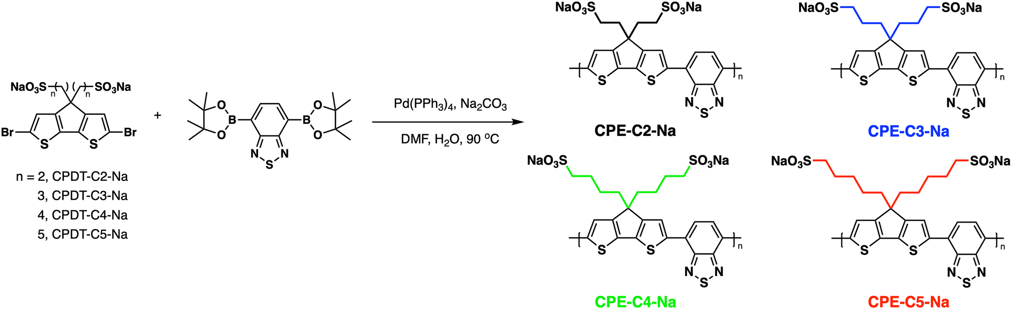 | ||
| Fig. 1 General pathway for Suzuki–Miyaura coupling polymerization and abbreviations used for the CPE synthesis. The CPEs were color-coded to facilitate data visualization. | ||
2. Results
2.1 Synthesis and characterization
Fig. 1 provides the chemical structures of the CPEs together with the synthetic approach for accessing the new structures. The synthesis of CPE-C4-Na and CPE-C3-Na has been previously reported.45,46 For CPE-C2-Na and CPE-C5-Na the synthetic pathway begins with alkylation of commercially available cyclopentadithiophene (CPDT) followed by bromination using N-bromosuccinimide (NBS). For CPE-C2-Na, alkylation of CPDT with sodium 2-bromoethanesulfonate was achieved under basic conditions, followed by bromination with NBS. Synthesis of CPE-C5-Na begins by alkylation of CPDT with excess 1,5-dibromopentane under basic conditions followed by bromination with NBS. At first, alkylation of CPDT led to low yields, possibly due to intramolecular cyclization (via two successive substitutions of Br in a single 1,5-dibromopentane molecule).47,48 An excess of 1,5-dibromopentane helped to circumvent this complication. A subsequent reaction with Na2SO3 in a refluxing mixture of EtOH/H2O, aided by tetrabutylammonium iodide (TBAI) as a phase-transfer reagent, afforded the anionic monomer, CPDT-C5-Na. The polymerization for all reported CPEs was achieved under Suzuki–Miyaura cross-coupling conditions. The purification procedure included precipitation of the product in acetone, filtration, and several washing steps with acetone and methanol. The resulting polymer product was purified by dialysis for three days in Millipore water, which afforded self-doped CPEs.49,50 Lyophilization produced dark blue solids. Detailed synthesis and characterization can be found in the ESI.† Counterion exchange with excess tetrabutylammonium bromide (TBABr) was performed to improve solubility in DMF and enabled gel permeation chromatography analysis.51 The number average molecular weight was determined to be 18.1 kg mol−1 (CPE-C2-Na), 15.0 kg mol−1 (CPE-C3-Na), 11.3 kg mol−1 (CPE-C4-Na), and 14.5 kg mol−1 (CPE-C5-Na).We examined the relative tendency for doping of the different CPE-CX-Na polymers using optical absorption spectroscopy. For sample preparation, CPEs were freeze-dried immediately after dialysis and used to make a 10 mg mL−1 solution. These were used to dropcast films onto a glass substrate or diluted to obtain the UV-Vis spectra of aqueous solutions. Optical spectra were measured between 300 nm and 1300 nm, see Fig. 2. One can observe characteristic absorption peaks around 400 nm and 680 nm (λmax), previously observed for donor–acceptor copolymers containing CPDT-alt-BT backbones.52,53 A first look into the absorption spectra shows a blue-shift in the neutral state absorption in CPE-C2-Na relative to the CPEs with a longer alkyl chain, see Fig. 2. The broad, low-energy transition starting at 900 nm for this class of CPEs has been attributed to transitions in the doped species (λpolaron).45 The ratio between the neutral state absorbance band (∼680 nm) and the polaron band should scale with the fraction of chains with polaronic states.54,55 Comparison of the relative intensity ratios between λpolaron and λmax indicates the impact of alkyl chain lengths on the doped levels, see Table S1 (ESI†). Going from 2 to 5 methylene units, the λpolaron/λmax ratio increases. CPE-C2-Na exhibits a ratio of 0.36, CPE-C3-Na of 0.59, CPE-C4-Na of 0.75 and CPE-C5-Na of 0.81 (Fig. 2(a)). UV-Vis spectroscopy measurements in thin films prepared from aqueous solutions reveal the same trend (Fig. 2(b)). The value of λpolaron/λmax in the film is highest for CPE-C5-Na (0.81), followed by CPE-C4-Na (0.79), CPE-C3-Na (0.64), and CPE-C2-Na (0.29). Considering that the sulfonate is thought to stabilize cationic polaronic states via Coulombic stabilization,50 it was expected that shorter alkyl chains would lead to a higher degree of doping. As mentioned above, the UV-Vis spectra demonstrate an opposite effect, which will be further analyzed in the electrochemical and theoretical sections of this paper.
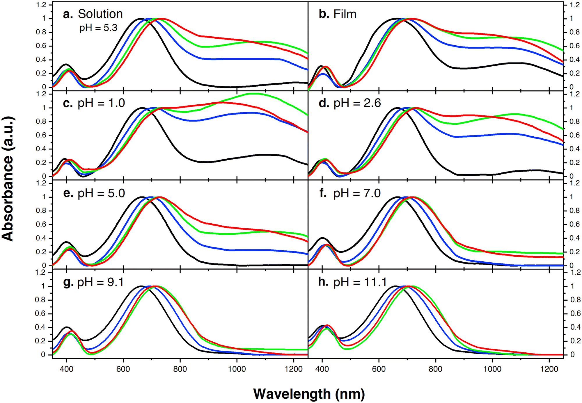 | ||
| Fig. 2 (a) Normalized ultraviolet-visible-near-infrared spectra (UV-Vis-NIR) of aqueous CPE solutions; (b) normalized UV-Vis-NIR spectra of CPE films deposited on ITO/glass substrates; pH dependent UV-Vis-NIR (normalized absorption) spectra at (c) pH = 1.0; (d) pH = 2.6; (e) pH = 5.0; (f) pH = 7.0; (g) pH = 9.1; and (h) pH = 11.1. Black: CPE-C2-Na, blue: CPE-C3-Na, green: CPE-C4-Na, and red: CPE-C5-Na. | ||
From our previous study, the proposed doping mechanism for the CPEs under study consists of two steps: (1) protonation of the CPDT unit of the polymer and (2) single electron transfer from a neutral polymer chain to the protonated polymer, resulting in one polymer chain with a positive polaron and another polymer chain with an unpaired electron.50,56Fig. 3 shows the chemical equation for the doping process as described previously and CPE-C4 is selected for illustrative purposes. Since the protonation of the cyclopentadithiophene will be related to its basicity, pH dependent UV-VIS measurements were conducted (Fig. 2(c–h)). Buffer solutions of pH of 1.0, 2.7, 5.0, 7.5, 9.2 and 11.3 were prepared. A solution of 3.3 μg mL−1 CPE in buffer was prepared and the solutions were allowed to equilibrate for 24 hours. After the UV-VIS measurement, the final pH of the solutions was determined. The intensity of the polaron absorption increased with lower pH value, indicating that the polaron concentration is higher. In a previous study with CPE-C4-K, a direct relationship between increased acidity and an increase in the polaron concentration was observed via electron paramagnetic resonance studies.57,58
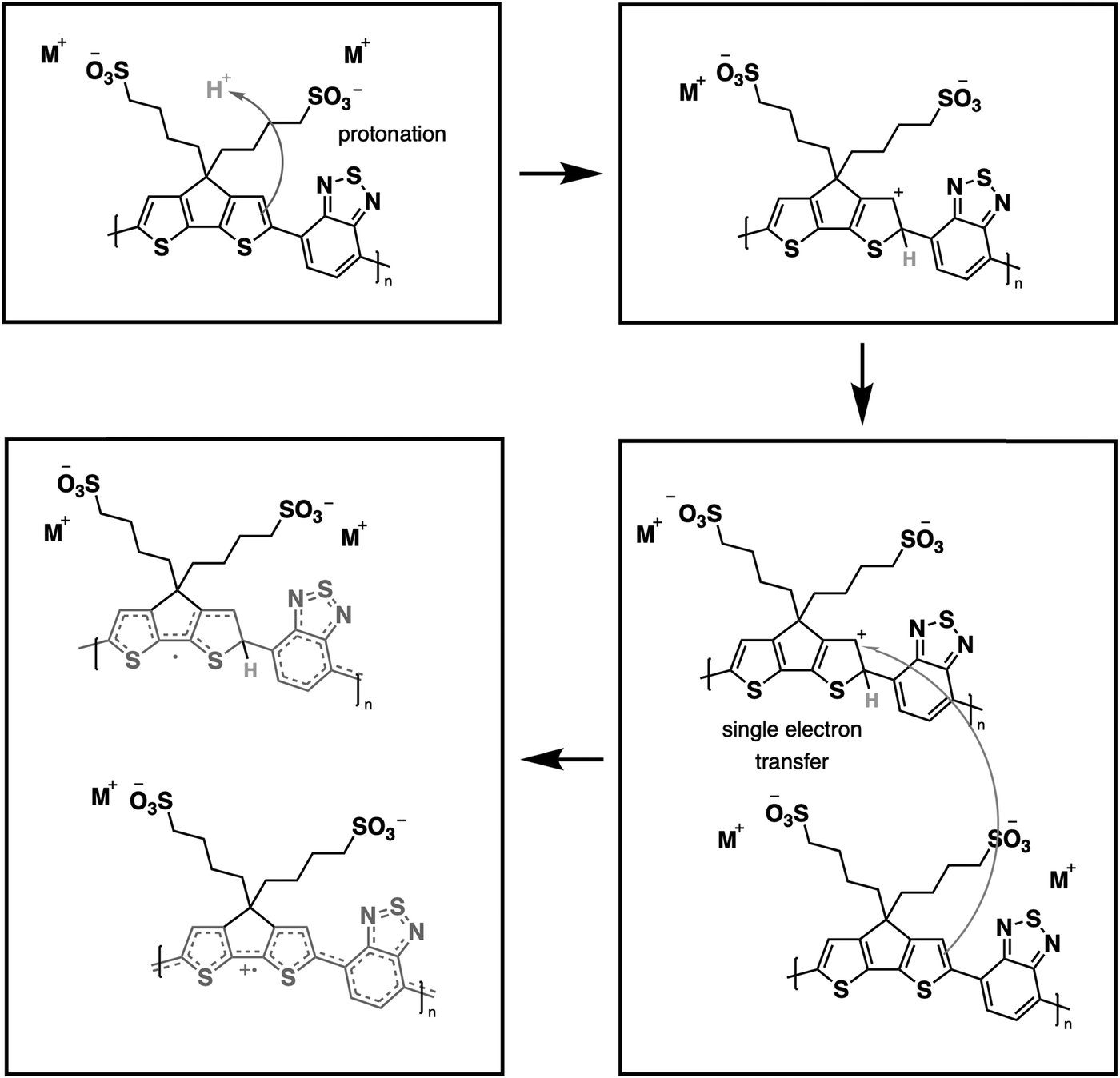 | ||
| Fig. 3 Schematic representation for protonic acid doping of CPE-C4 adapted from ref. 58. | ||
Differential pulse voltammetry (DPV) was used to probe electrochemical properties as a function of chemical structure. This technique was selected over cyclic voltammetry to probe the thermodynamics of the system due to its ability to minimize background current resulting in a more sensitive measurement of faradaic current.59,60 The oxidation onsets of CPE films were measured in an aqueous solution. Fig. 4(a) provides the response of CPE-CX-Na films in the DPV experiment. The following oxidation potentials (vs. SCE) were measured Eox = 0.77 V (CPE-C2-Na), Eox = 0.60 V (CPE-C3-Na and CPE-C4-Na) and Eox = 0.56 V (CPE-C5-Na). Non-normalized voltammograms can be found in the ESI† (Fig. S1). DPV data for the CPE-CX-Na series suggest an electron withdrawing effect by the sulfonate group,61 which increases Eox and thereby disfavors the electron transfer step in Fig. 3. To further confirm an electron withdrawing effect, DPV was carried out on the alkylated cyclopentadithiophene monomers (CPDT-CX-Na in Fig. 1). As expected, the voltammograms on monomeric units are easier to interpret (Fig. 4(b)) and can provide more clear information on the influence of the distance between sulfonate group and backbone on the redox potential. The measured potentials vs. SCE were Eox = 0.76 V for CPDT-C5, increasing to Eox = 0.78 V for CPDT-C4 and CPDT-C3 and Eox = 0.85 V for CPDT-C2. Thus, the general trend in Fig. 4(b) is an increase in the oxidation potential with decreasing distance between the sulfonate group and the CPDT. Non-normalized data can be found in the ESI† (Fig. S2). The electrochemical data therefore agree with the absorbance data. Furthermore, in Fig. 2, a blueshift in the absorption was observed for CPE-C2-Na relative to the longer alkyl chain CPEs, which can be explained by an electron withdrawing effect that makes the CPDT fragment a weaker donor.
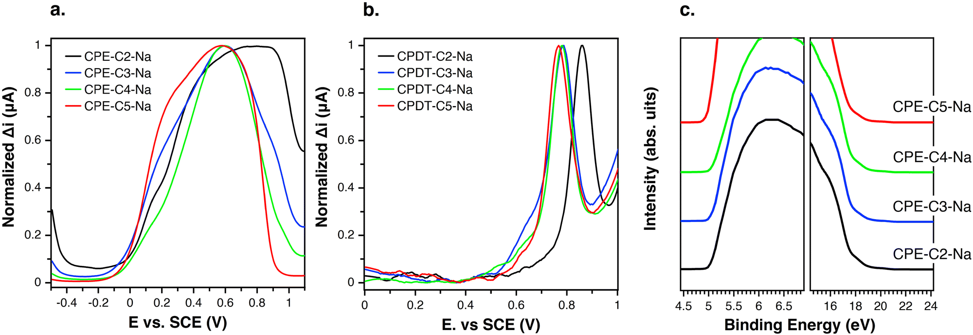 | ||
| Fig. 4 (a) Normalized differential pulsed voltammetry on dropcast CPE films measured in aqueous solution (0.1 M NaCl); glassy carbon working electrode, saturated calomel as a reference electrode and platinum wire as a counter electrode; (b) normalized differential pulsed voltammetry on films (dropcast) of alkylated cyclopentadithiophene derivatives measured in aqueous solution (0.1 M NaCl); (c) UPS data in the high binding cut off region and highest occupied state. The ionization potential was measured by subtracting the difference between the energy of the incident photon and the width of the spectrum. | ||
The effect of alkyl chain length on the degree of doping may also be understood by considering the effect of chain flexibility. A higher number of methylene units in the alkyl chain translate to a larger conformational space, and therefore, to a more frequent close proximity of the sulfonate group to the conjugated backbone. Such a situation would lead to a higher degree of polaron stabilization and a higher degree of doping by means of through-space coulombic stabilization.
Comparing Fig. 4(a) and (b) one can see that, relative to the oxidation peak for monomers, the oxidation peak for the CPEs is broader and appears at lower potentials. The extended conjugation in the polymer results in the lowering of the oxidation potential compared to the monomer. With an increasing chain length of the system, the number of accessible redox states increases, which results in a superposition of redox states over a broad potential range.62 Furthermore, the dispersity of the chains favors the superposition of redox states.62
Ultraviolet-photoelectron spectroscopy (UPS) was carried out (Fig. 4(c)) on films of CPE-C2-Na, CPE-C3-Na, CPE-C4-Na, and CPE-C5-Na spin-coated atop ITO/glass substrates. The abscissa is the binding energy relative to the Fermi level of Au (EF), which is defined by the energy of the electron before excitation relative to the vacuum level. The ionization potential (IP) onsets were obtained from the low energy region. The values for ionization potential (IP) obtained using this technique were −5.2 eV (CPE-C2-Na), −5.2 eV (CPE-C3-Na), −5.2 eV (CPE-C4-Na), and −5.2 eV (CPE-C5-Na). The IP values were the same for all CPEs. Table 1 summarizes the data obtained for electrochemical characterization.
| CPE | E ox (V vs. SCE) | IP (eV) |
|---|---|---|
| CPE-C2-Na | 0.77 | −5.2 |
| CPE-C3-Na | 0.6 | −5.2 |
| CPE-C4-Na | 0.6 | −5.2 |
| CPE-C5-Na | 0.56 | −5.2 |
2.2 Theoretical studies
DFT was used to bring more insights into the doping level differences. The geometry optimizations and electronic structure calculations were performed at the ωB97XD/6-31G(d)3 level of DFT with three repeat units of CPE. The energy levels of CPE and CPE+ (from Fig. 3) are illustrated in Fig. 5(a) and the electronic transition from the highest occupied molecular orbital (HOMO) to the lowest unoccupied molecular orbital (LUMO) corresponds to λmax observed in the experiment. In CPE+, unoccupied in-gap states are generated (polaron states) that are responsible for the redshift in absorption, i.e., the appearance of a new transition (λpolaron). The intensity of λpolaron is proportional to the concentration of CPE+ and the oscillator strength of the polaron transition. To compare the concentration of the polarons in the polymer films, the formation energies of CPE+-CX-Na (X = 2, 3, 4, and 5) were calculated following the equation from Fig. 3. As summarized in Fig. 5(b), the formation energy of CPE+-CX-Na (X = 2, 3, 4, and 5) decreases monotonously from C2 to C5. Since a larger formation energy would translate to a lower concentration of positive polarons, we find that the polaron concentration is higher when a longer alkyl chain length is included. The calculated oscillator strengths of the main peaks for CPE+-CX-Na (X = 2, 3, 4, and 5) are summarized in Fig. 5(b), and no obvious difference can be found among the various alkyl chain lengths. Based on the above analysis, it can be concluded that the intensity of λpolaron in Fig. 2(a) and (b) is attributed to the lower formation energy of CPE+-CX-Na with longer alkyl chain lengths. | ||
| Fig. 5 (a) The energy levels of CPE-C4-Na and CPE+-C4-Na; (b) the oscillator strength and formation energy of each CPE+-CX-Na (X = 2, 3, 4, and 5). | ||
2.3 Morphology study of CPEs
Grazing incidence wide-angle X-ray scattering (GIWAXS) was employed to study the structural organization of drop-cast films on Si substrates (Fig. 6). A scattering peak along the qz direction at 0.7–0.9 Å−1 is observed, and the position of the peak scattering shifts to smaller Å−1, which corresponds to a longer lamellar distance (from 0.71 nm to 0.87 nm) upon increasing the alkyl side chains. Notably, the coherence length (CL) also significantly increases (from 1.67 to 5.33) that indicates a better packing order is obtained upon increasing the length of alkyl side chains. All detailed analyses of the crystal are summarized in Table S2 (ESI†). Line cuts extracted from the 2D images of the films along with out-of-plane and in-plane directions are found in Fig. S3. In addition, the scattering around 1.7 Å−1 along the qxy plane is also found which corresponds to a π–π stacking distance of 0.36 nm. No measurable difference in the π–π stacking distance is observed for the CPE films except CPE-C2-Na which possesses a longer distance (0.38 nm) which is unfavorable for charge transport. We do not observe the intense scattering peak in CPE-C2-Na, which suggests that the material is the least ordered. From the analysis, CL of π–π stacking also increases (from 1.55 nm to 3.69 nm) with increasing alkyl side chains.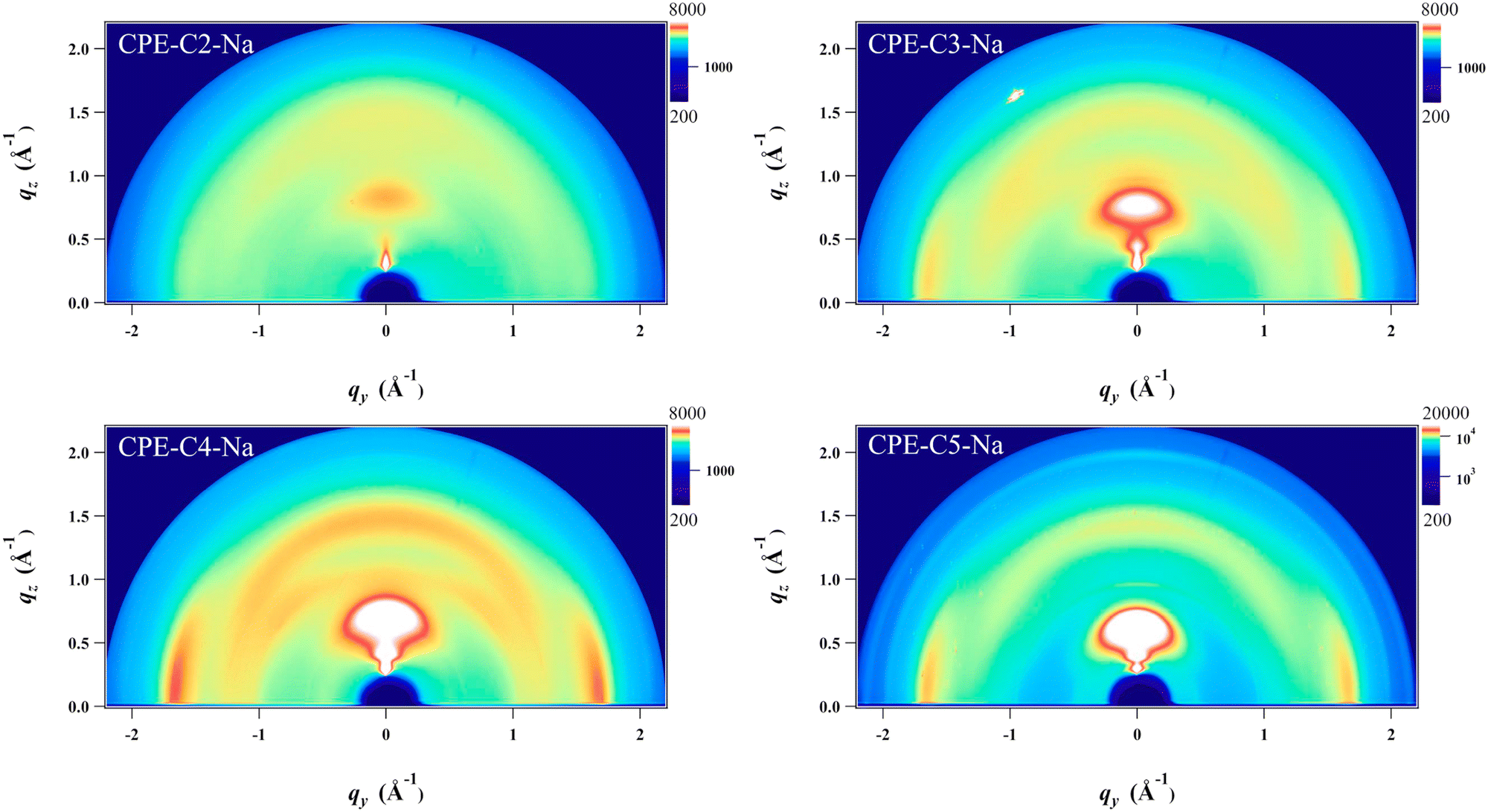 | ||
| Fig. 6 Grazing-incidence wide-angle X-ray scattering (GIWAXS) images of drop-cast CPE films on silicon substrates. | ||
2.4 CPEs as the active layer in OECTs
Preliminary OECT characterization was performed to understand the impact of chain length variation on device performance. Fig. 7(a) contains the general device architecture used for our measurements. A 0.1 M solution of NaCl was used as the gate electrolyte and an Ag/AgCl pellet as the gate electrode (and pseudo-reference electrode). The CPE films were processed from water and therefore needed to be stabilized with a cross-linker, (3-glycidyloxypropyl)trimethoxysilane (GOPS), to avoid dissolution into the electrolyte medium. CPE solutions were thus prepared with GOPS as previously described.22 A preliminary study with varying amounts of GOPS in each CPE established the minimal percentage of GOPS that resulted in stable films and the highest conductivity. The percentages of GOPs were determined to be 32% wt for CPE-C2-Na, CPE-C3-Na and CPE-C4-Na, while 16% wt worked best for CPE-C5-Na.22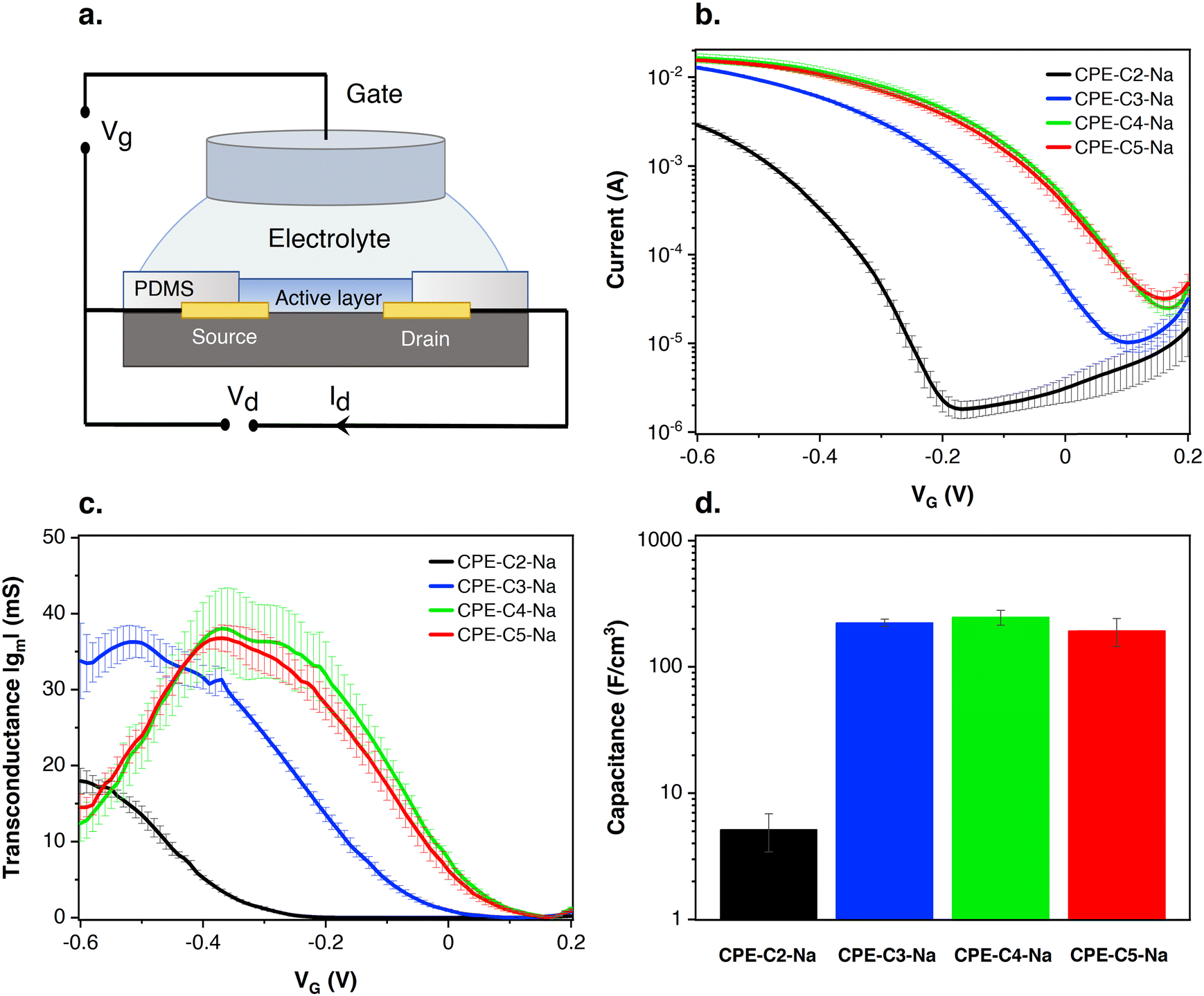 | ||
| Fig. 7 (a) Device architecture of CPE-based OECTs; (b) transfer characteristics at VD = −0.6 V of OECTs made using interdigitated contacts (W = 27 cm, L = 8 μm, d = 1.5–1.9 μm); (c) transconductance values at VD = −0.6 V of OECTs made with interdigitated contacts. (d) Volumetric capacitance measured by impedance spectroscopy. | ||
Multiple sets of the CPE-based OECT devices were tested and the average transfer characteristics are provided in Fig. 7(b). Fig. S4 (ESI†) shows the transfer characteristics of each run. In Fig. 7(b), when a negative gate voltage is applied, Cl− ions are introduced into the active layer. There, charges are balanced by hole injection from the source electrode, increasing the charge carrier density and therefore conductivity in the channel.63 The negative source–drain voltage (VD = −0.6 V) provides the driving force for hole migration, giving rise to the source–drain current (IDS). In Fig. 7(b), under increasingly negative VG, the magnitude of IDS increases, characteristic of a p-type accumulation mode OECT. Accumulation-mode OECT devices operate in the ON state and rest in the OFF state, and consume less power compared to depletion mode OECTs, which rest in the ON state. For CPE-C4-Na and CPE-C5-Na IDS saturates when VG = −0.6 V. The curve for CPE-C3-Na and CPE-C2-Na still shows an ascendant behavior at that voltage. Recently, OECTs based on CPE-C4-K have demonstrated the unique property of operating in the dual-mode. Under an applied negative voltage, the anion migrates and dopes CPE-C4-K, acting as accumulation mode device. In contrast, it can act in depletion mode due to the dedoping under the cation migration owing to the self-doping properties.64
In Fig. 7(b), the threshold voltages (VT) of different alkyl chain length CPEs are shifted by hundreds of millivolts. The threshold voltage is the gate voltage at which significant current starts to flow from the source to the drain.65 The different VT indicates a different degree of doping at specific VG. VT values were determined by extrapolating the corresponding IDS1/2vs. VG plots following a methodology reported previously (Fig. S5, ESI†).66,67VT values of −300 mV vs. Ag/AgCl (CPE-C2-Na), −30 mV vs. Ag/AgCl (CPE-C3-Na), 80 mV vs. Ag/AgCl (CPE-C4-Na), and 70 mV vs. Ag/AgCl (CPE-C5-Na) were found. VT of less than |0.25| V enables low voltage operation in OECT devices, which include CPEs with alkyl chains of 3, 4 and 5 methylene units.68 We note that low threshold voltage is advantageous for sensing applications.69,70
The steeper the subthreshold slope, the larger the change in IDS for a given change in VG. The slope of the transfer curve is the transconductance (gm), which indicates the signal amplification of the OECT. Under a saturation regime, gm is given by
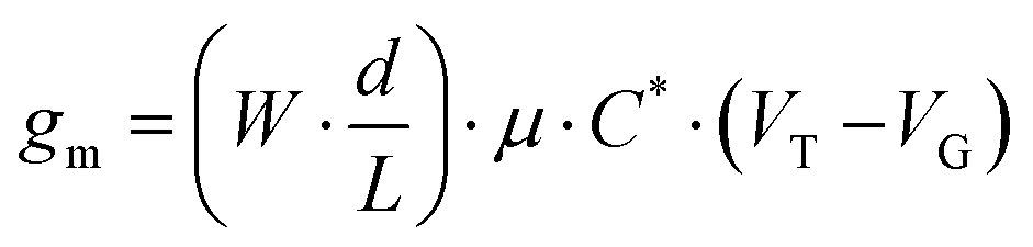 | (1) |
| CPE | V T (vs. Ag/AgCl) | g m |
|---|---|---|
| CPE-C2-Na | −300 mV | 18.0 ± 2 mS |
| CPE-C3-Na | −30 mV | 36.3 ± 2 mS |
| CPE-C4-Na | 80 mV | 38.1 ± 5 mS |
| CPE-C5-Na | 70 mV | 36.8 ± 2 mS |
From the GIWAXs data, there is an increase in film crystallinity for a higher number of methylene units. The higher crystallinity appears to be correlated with more ordered domains and thus higher hole conductivity, resulting in OECT devices with better performance. Fig. S7 of the ESI† shows the surface topographic images measured by atomic force microscopy (AFM) of CPE-CX-Na. The surface morphology of the CPE-CX-Na films does not change with increasing side-chain length. All films look smooth with a root mean square roughness between 0.3 and 0.4 nm.
Electrochemical capacitance quantifies the result of ion uptake of the film.71 The doping process in our OECT devices involves Cl− anion injection from the electrolyte into the active layer and the hole injection from the metal contact, forming sites of anion/hole pairs. A capacitor is formed between these two charge carriers originating the capacitance of the film. Eqn (1) shows that gm is proportional to C*. Impedance spectroscopy was thus used to measure the capacitance (C) (Fig. S8 in the ESI†), which was divided by the volume of the CPE layer (Fig. 7(d)). Normalized to the volume, the volumetric capacitance obtained is as follows: 5.1 ± 1.7 F cm−3 (CPE-C2-Na), (2.2 ± 0.2) × 102 F cm−3 (CPE-C3-Na), (2.5 ± 0.3) × 102 F cm−3 (CPE-C4-Na), and (1.9 ± 0.5) × 102 F cm−3 (CPE-C5-Na). CPE-C2-Na exhibits a lower volumetric capacitance while the values observed for CPE-C3-Na, CPE-C4-Na and CPE-C5-Na are similar within an error. We believe that the volumetric capacitance of CPE-C2 is lower due to the shorter side chain length and low self-doping level. When the side length chains are shorten, the CPE-C2 has smaller volume for ion uptake. Significantly smaller lamella distance (C2: 0.71 nm and C5: 0.87 nm) was confirmed by GIWAXS analysis. Both factors influence to the volumetric capacitance of CPE-C2, which decreases as the number of average charge per monomer unit decreases.71 The UV-Vis absorption spectrum shows a much lower absorption at 1180 nm (polaron absorption) of C2 compared to C3-5,64 indicating a significantly lower self-doping efficiency, a.k.a. lower average charge per monomer unit. We observed a similar trend with a dedoped CPE-C4-K which shows two orders of magnitude smaller capacitance than the doped one.22
Finally, the relative ion transport of the CPEs in the dry state was evaluated using electrochemical impedance spectroscopy (EIS) (Fig. S9, ESI†).72–74 A challenge associated with the measurement of CPE films is that as a conductive polymer, the high electronic conductivity would hinder measuring the ion transport. To address this and knowing that water is responsible for the self-doping efficiency of CPE-CX-Na,50 the films were annealed. CPE-CX-Na films were deposited on interdigitated contacts at 300 °C to drive water out of the film, thus reversibly de-doping the film without decomposing it.50 Between two electrodes of each interdigitated contact, an AC voltage of 20 mV was applied at a frequency from 10 Hz to 10 MHz. Representative Nyquist plots of each CPE material are shown in Fig. S9 (ESI†). By fitting these plots with an equivalent circuit in Fig. S10 (ESI†),72 the estimated values of ion conductivity of CPE-CX-Na in the dry state were 1.96 × 10⁻⁴ S cm−1 (CPE-C2-Na), 1.64 × 10⁻⁴ S cm−1 (CPE-C3-Na), 6.34 × 10⁻⁵ S cm−1 (CPE-C4-Na), 3.65 × 10⁻⁵ S cm−1 (CPE-C5-Na). A decrease in ion conductivity is observed as the sidechain length is increased, which is attributed to the higher hydrophobic content and higher film crystallinity.
3. Conclusion
In conclusion, we have presented a systematic structure–property-relationship study on CPEs with varying side-chain lengths. Before studying this particular series of CPEs, it was hypothesized that the proximity of the polaron-stabilizing negative charge would increase the ease of doping as their side-chain length is decreased. However, the opposite trend was observed using UV-VIS spectroscopy. DPV of films consisting of cyclopentadithiophene derivatives as well as CPE films demonstrated a reduction in the oxidation potential with the increase in chain length. The lower oxidation potential can be interpreted with an increase in the ease of polaron formation. GIWAXS data showed an increase in crystallinity with side chain lengths which is indicative of a higher hole mobility. Finally, in DFT studies a lower formation energy was found in systems with longer alkyl chain lengths. The initial structure–property characterization suggests an electron withdrawing effect of the sulfonate group on the cyclopentadithiophene ring, making difficult the oxidation of the polymer and therefore doping. In addition, the higher flexibility of longer alkyl chain lengths can favor an approximation of the sulfonate group to the polaron, leading to a higher degree of polaron stabilization and a higher degree of doping by means of through-space coulombic stabilization. This highlights the relevance of a systematic study of conjugated polyelectrolytes to assist in the design of better materials. We concluded that a shorter alkyl chain length disfavors the oxidation onset in our system and consequently reduces the doping level of the conjugated polyelectrolyte. To further explore the potential of modulating the CPE properties by alkyl chain lengths we performed a non-optimized OECT study. Although multiple aspects of device assembly can impact the properties, we discussed characteristics that we believe to be modulated by alkyl chain lengths. CPE-CX-Na, with X = 3, 4 and 5, remain viable candidates for OECT application. CPE-C2-Na shows the lowest transconductance. CPE-C3-Na, CPE-C4-Na and CPE-C5-Na show similar levels of transconductance, higher than that of CPE-C2-Na. The OECT performance is further supported by the volumetric capacitance of each CPE.Author contributions
L. C. L. drafted the concept of the manuscript; A. T. L., Y. W., and S. C. contributed to draft preparation and editing of the manuscript; L. C. L. synthesized the materials, and collected electrochemistry data and absorption in solution data; A. T. L. collected absorption in films data and made and characterized the OECT devices; S. C., A. Y., and H. J. K. measured and analyzed the morphological characteristics; Y. W. contributed to the theoretical section; S. C, T. D. N. contributed to OECT-related data interpretation; and G. C. B., T. C. N., and G. L. supervised the project, edited and revised the manuscript.Conflicts of interest
There are no conflicts to declare.Acknowledgements
This work was supported by the U.S. National Science Foundation (DMREF-1922042).References
- H. Jiang, P. Taranekar, J. R. Reynolds and K. S. Schanze, Angew. Chem., Int. Ed., 2009, 48, 4300–4316 CrossRef CAS PubMed.
- W. Lee, J. H. Seo and H. Y. Woo, Polymer, 2013, 54, 5104–5121 CrossRef CAS.
- B. D. Paulsen, K. Tybrandt, E. Stavrinidou and J. Rivnay, Nat. Mater., 2020, 19, 13–26 CrossRef CAS PubMed.
- C. Musumeci, M. Vagin, E. Zeglio, L. Ouyang, R. Gabrielsson and O. Inganäs, J. Mater. Chem. C, 2019, 7, 2987–2993 RSC.
- A. O. Patil, Y. Ikenoue, N. Basescu, N. Colaneri, J. Chen, F. Wudl and A. J. Heeger, Synth. Met., 1987, 20, 151–159 CrossRef CAS.
- Z. Wu, C. Sun, S. Dong, X.-F. Jiang, S. Wu, H. Wu, H.-L. Yip, F. Huang and Y. Cao, J. Am. Chem. Soc., 2016, 138, 2004–2013 CrossRef CAS PubMed.
- J. H. Seo, A. Gutacker, Y. Sun, H. Wu, F. Huang, Y. Cao, U. Scherf, A. J. Heeger and G. C. Bazan, J. Am. Chem. Soc., 2011, 133, 8416–8419 CrossRef CAS PubMed.
- C. Sun, Z. Wu, Z. Hu, J. Xiao, W. Zhao, H.-W. Li, Q.-Y. Li, S.-W. Tsang, Y.-X. Xu, K. Zhang, H.-L. Yip, J. Hou, F. Huang and Y. Cao, Energy Environ. Sci., 2017, 10, 1784–1791 RSC.
- Z. Hu, R. Xu, S. Dong, K. Lin, J. Liu, F. Huang and Y. Cao, Mater. Horiz., 2017, 4, 88–97 RSC.
- C. V. Hoven, R. Yang, A. Garcia, V. Crockett, A. J. Heeger, G. C. Bazan and T.-Q. Nguyen, Proc. Natl. Acad. Sci. U. S. A., 2008, 105, 12730–12735 CrossRef CAS PubMed.
- J. Fang, B. H. Wallikewitz, F. Gao, G. Tu, C. Müller, G. Pace, R. H. Friend and W. T. S. Huck, J. Am. Chem. Soc., 2011, 133, 683–685 CrossRef CAS PubMed.
- X. Zhu, Y. Xie, X. Li, X. Qiao, L. Wang and G. Tu, J. Mater. Chem., 2012, 22, 15490 RSC.
- J. H. Seo, A. Gutacker, B. Walker, S. Cho, A. Garcia, R. Yang, T.-Q. Nguyen, A. J. Heeger and G. C. Bazan, J. Am. Chem. Soc., 2009, 131, 18220–18221 CrossRef CAS PubMed.
- J. H. Seo, E. B. Namdas, A. Gutacker, A. J. Heeger and G. C. Bazan, Adv. Funct. Mater., 2011, 21, 3667–3672 CrossRef CAS.
- G. Feng, D. Ding and B. Liu, Nanoscale, 2012, 4, 6150 RSC.
- S. R. Mccuskey, Y. Su, D. Leifert, A. S. Moreland and G. C. Bazan, Adv. Mater., 2020, 1908178, 1–6 Search PubMed.
- Y. Su, S. R. Mccuskey, D. Leifert, A. S. Moreland, L. Zhou, L. C. Llanes, R. J. Vazquez, L. Sepunaru and G. C. Bazan, Adv. Funct. Mater., 2021, 31(6), 2007351 CrossRef CAS.
- G. Feng, C. K. Mai, R. Zhan, G. C. Bazan and B. Liu, J. Mater. Chem. B, 2015, 3, 7340–7346 RSC.
- E. Zamani, T. J. Johnson, S. Chatterjee, C. Immethun, A. Sarella, R. Saha and S. K. Dishari, ACS Appl. Mater. Interfaces, 2020, 12, 49346–49361 CrossRef CAS PubMed.
- E. Ji, A. Parthasarathy, T. S. Corbitt, K. S. Schanze and D. G. Whitten, Langmuir, 2011, 27, 10763–10769 CrossRef CAS PubMed.
- E. Zamani, S. Chatterjee, T. Changa, C. Immethun, A. Sarella, R. Saha and S. K. Dishari, Sci. Rep., 2019, 9, 20411 CrossRef CAS PubMed.
- A. T. Lill, D. X. Cao, M. Schrock, J. Vollbrecht, J. Huang, T. Nguyen-Dang, V. V. Brus, B. Yurash, D. Leifert, G. C. Bazan and T. Q. Nguyen, Adv. Mater., 2020, 32, 1–9 CrossRef PubMed.
- M. M. Schmidt, M. ElMahmoudy, G. G. Malliaras, S. Inal and M. Thelakkat, Macromol. Chem. Phys., 2018, 219, 1–10 Search PubMed.
- E. Zeglio, M. M. Schmidt, M. Thelakkat, R. Gabrielsson, N. Solin and O. Inganäs, Chem. Mater., 2017, 29, 4293–4300 CrossRef CAS.
- S. Inal, J. Rivnay, P. Leleux, M. Ferro, M. Ramuz, J. C. Brendel, M. M. Schmidt, M. Thelakkat and G. G. Malliaras, Adv. Mater., 2014, 26, 7450–7455 CrossRef CAS PubMed.
- D. Khodagholy, T. Doublet, P. Quilichini, M. Gurfinkel, P. Leleux, A. Ghestem, E. Ismailova, T. Hervé, S. Sanaur, C. Bernard and G. G. Malliaras, Nat. Commun., 2013, 4, 1575 CrossRef PubMed.
- D. Khodagholy, J. N. Gelinas, T. Thesen, W. Doyle, O. Devinsky, G. G. Malliaras and G. Buzsáki, Nat. Neurosci., 2015, 18, 310–315 CrossRef CAS PubMed.
- J. Rivnay, H. Wang, L. Fenno, K. Deisseroth and G. G. Malliaras, Sci. Adv., 2017, 3(6) DOI:10.1126/sciadv.1601649.
- D. Khodagholy, J. N. Gelinas, Z. Zhao, M. Yeh, M. Long, J. D. Greenlee, W. Doyle, O. Devinsky and G. Buzsáki, Sci. Adv., 2016, 2(11) DOI:10.1126/sciadv.1601027.
- Y. J. Jo, K. Y. Kwon, Z. U. Khan, X. Crispin and T. Il Kim, ACS Appl. Mater. Interfaces, 2018, 10, 39083–39090 CrossRef CAS PubMed.
- G. Scheiblin, R. Coppard, R. M. Owens, P. Mailley and G. G. Malliaras, Adv. Mater. Technol., 2017, 2, 1–5 Search PubMed.
- D. Khodagholy, V. F. Curto, K. J. Fraser, M. Gurfinkel, R. Byrne, D. Diamond, G. G. Malliaras, F. Benito-Lopez and R. M. Owens, J. Mater. Chem., 2012, 22, 4440–4443 RSC.
- M. Braendlein, A. M. Pappa, M. Ferro, A. Lopresti, C. Acquaviva, E. Mamessier, G. G. Malliaras and R. M. Owens, Adv. Mater., 2017, 29, 1605744 CrossRef PubMed.
- E. Macchia, P. Romele, K. Manoli, M. Ghittorelli, M. Magliulo, Z. M. Kovács-Vajna, F. Torricelli and L. Torsi, Flexible Printed Electron., 2018, 3(3), 034002 CrossRef.
- A. M. Pappa, D. Ohayon, A. Giovannitti, I. P. Maria, A. Savva, I. Uguz, J. Rivnay, I. McCulloch, R. M. Owens and S. Inal, Sci. Adv., 2018, 4, 1–8 Search PubMed.
- O. Parlak, S. T. Keene, A. Marais, V. F. Curto and A. Salleo, Sci. Adv., 2018, 4(7), 10.1126/sciadv.aar2904 Search PubMed.
- J. Borges-González, C. J. Kousseff and C. B. Nielsen, J. Mater. Chem. C, 2019, 7, 1111–1130 RSC.
- N. Wang, A. Yang, Y. Fu, Y. Li and F. Yan, Acc. Chem. Res., 2019, 52(2), 277–287 CrossRef CAS PubMed.
- C. Diacci, J. W. Lee, P. Janson, G. Dufil, G. Méhes, M. Berggren, D. T. Simon and E. Stavrinidou, Adv. Mater. Technol., 2020, 5(3), 1900262 CrossRef CAS.
- S. Wustoni, C. Combe, D. Ohayon, M. H. Akhtar, I. McCulloch and S. Inal, Adv. Funct. Mater., 2019, 29, 1–10 CrossRef.
- T. Someya, Z. Bao and G. G. Malliaras, Nature, 2016, 540, 379–385 CrossRef CAS PubMed.
- J. Rivnay, S. Inal, A. Salleo, R. M. Owens, M. Berggren and G. G. Malliaras, Nat. Rev. Mater., 2018, 3, 17086 CrossRef CAS.
- D. A. Bernards and G. G. Malliaras, Adv. Funct. Mater., 2007, 17, 3538–3544 CrossRef CAS.
- C. B. Nielsen, A. Giovannitti, D. T. Sbircea, E. Bandiello, M. R. Niazi, D. A. Hanifi, M. Sessolo, A. Amassian, G. G. Malliaras, J. Rivnay and I. McCulloch, J. Am. Chem. Soc., 2016, 138, 10252–10259 CrossRef CAS PubMed.
- C. K. Mai, H. Zhou, Y. Zhang, Z. B. Henson, T. Q. Nguyen, A. J. Heeger and G. C. Bazan, Angew. Chem., Int. Ed., 2013, 52, 12874–12878 CrossRef CAS PubMed.
- C. K. Mai, B. Russ, S. L. Fronk, N. Hu, M. B. Chan-Park, J. J. Urban, R. A. Segalman, M. L. Chabinyc and G. C. Bazan, Energy Environ. Sci., 2015, 8, 2341–2346 RSC.
- B. Liu, B. S. Gaylord, S. Wang and G. C. Bazan, J. Am. Chem. Soc., 2003, 125, 6705–6714 CrossRef CAS PubMed.
- W. Lee, J. H. Seo and H. Y. Woo, Polymer, 2013, 54, 5104–5121 CrossRef CAS.
- C. K. Mai, H. Zhou, Y. Zhang, Z. B. Henson, T. Q. Nguyen, A. J. Heeger and G. C. Bazan, Angew. Chem., Int. Ed., 2013, 52, 12874–12878 CrossRef CAS PubMed.
- D. X. Cao, D. Leifert, V. V. Brus, M. S. Wong, H. Phan, B. Yurash, N. Koch, G. C. Bazan and T.-Q. Nguyen, Mater. Chem. Front., 2020, 4, 3556–3566 RSC.
- R. Yang, A. Garcia, D. Korystov, A. Mikhailovsky, G. C. Bazan and T.-Q. Nguyen, J. Am. Chem. Soc., 2006, 128, 16532–16539 CrossRef CAS PubMed.
- C. Soci, I. W. Hwang, D. Moses, Z. Zhu, D. Waller, R. Gaudiana, C. J. Brabec and A. J. Heeger, Adv. Funct. Mater., 2007, 17, 632–636 CrossRef CAS.
- D. Mühlbacher, M. Scharber, M. Morana, Z. Zhu, D. Waller, R. Gaudiana and C. Brabec, Adv. Mater., 2006, 18, 2884–2889 CrossRef.
- Z. Liang, M. J. Boland, K. Butrouna, D. R. Strachan and K. R. Graham, J. Mater. Chem. A, 2017, 5, 15891–15900 RSC.
- J. Yamamoto and Y. Furukawa, J. Phys. Chem. B, 2015, 119, 4788–4794 CrossRef CAS PubMed.
- C. C. Han and R. L. Elsenbaumer, Synth. Met., 1989, 30, 123–131 CrossRef CAS.
- D. Tsokkou, L. Peterhans, D. X. Cao, C. Mai, G. C. Bazan, T. Nguyen and N. Banerji, Adv. Funct. Mater., 2020, 30, 1906148 CrossRef CAS.
- P. S. Marqués, G. Londi, B. Yurash, T.-Q. Nguyen, S. Barlow, S. R. Marder and D. Beljonne, Chem. Sci., 2021, 12, 7012–7022 RSC.
- B. Jill Venton and D. J. DiScenza, Electrochemistry for Bioanalysis, Elsevier, 2020 Search PubMed.
- S. Rasmussen, in Encyclopedia of Polymeric Nanomaterials, ed. S. Kobayashi and K. Müllen, Springer Berlin Heidelberg, Berlin, Heidelberg, 2013, pp.1–13 Search PubMed.
- Z. J. Zhang and X. Y. Chen, Electrochim. Acta, 2018, 282, 563–574 CrossRef CAS.
- J. Heinze, B. A. Frontana-Uribe and S. Ludwigs, Chem. Rev., 2010, 110, 4724–4771 CrossRef CAS PubMed.
- R. Colucci, H. F. de, P. Barbosa, F. Günther, P. Cavassin and G. C. Faria, Flexible Printed Electron., 2020, 5, 013001 CrossRef CAS.
- T. Nguyen-Dang, S. Chae, J. Chatsirisupachai, H. Wakidi, V. Promarak, Y. Visell and T. Nguyen, Adv. Mater., 2022, 34, 2200274 CrossRef CAS PubMed.
- Y. Taur, Encyclopedia of Materials: Science and Technology, Elsevier, 2001, pp. 9430–9444 Search PubMed.
- A. Savva, R. Hallani, C. Cendra, J. Surgailis, T. C. Hidalgo, S. Wustoni, R. Sheelamanthula, X. Chen, M. Kirkus, A. Giovannitti, A. Salleo, I. McCulloch and S. Inal, Adv. Funct. Mater., 2020, 30, 1907657 CrossRef CAS.
- N. Wang, L. Xie, H. Ling, V. Piradi, L. Li, X. Wang, X. Zhu and F. Yan, J. Mater. Chem. C, 2021, 9, 4260–4266 RSC.
- C.-Y. Yang, D. Tu, T.-P. Ruoko, J. Y. Gerasimov, H.-Y. Wu, P. C. Harikesh, R. Kroon, C. Müller, M. Berggren and S. Fabiano, arXiv:2106.07438 [cond-mat, physics:physics].
- J. Rivnay, P. Leleux, M. Sessolo, D. Khodagholy, T. Hervé, M. Fiocchi and G. G. Malliaras, Adv. Mater., 2013, 25, 7010–7014 CrossRef CAS PubMed.
- S. E. Doris, A. Pierre and R. A. Street, Adv. Mater., 2018, 30, 1706757 CrossRef PubMed.
- C. M. Proctor, J. Rivnay and G. G. Malliaras, J. Polym. Sci., Part B: Polym. Phys., 2016, 54, 1433–1436 CrossRef CAS.
- B. X. Dong, C. Nowak, J. W. Onorato, J. Strzalka, F. A. Escobedo, C. K. Luscombe, P. F. Nealey and S. N. Patel, Chem. Mater., 2019, 31, 1418–1429 CrossRef CAS.
- B. X. Dong, Z. Liu, M. Misra, J. Strzalka, J. Niklas, O. G. Poluektov, F. A. Escobedo, C. K. Ober, P. F. Nealey and S. N. Patel, ACS Nano, 2019, 13, 7665–7675 CrossRef CAS PubMed.
- B. X. Dong, P. Bennington, Y. Kambe, D. Sharon, M. Dolejsi, J. Strzalka, V. F. Burnett, P. F. Nealey and S. N. Patel, Mol. Syst. Des. Eng., 2019, 4, 597–608 RSC.
Footnotes |
| † Electronic supplementary information (ESI) available. See DOI: https://doi.org/10.1039/d3tc00355h |
| ‡ These authors contributed equally to this paper. |
| This journal is © The Royal Society of Chemistry 2023 |