DOI:
10.1039/D2TC04600H
(Paper)
J. Mater. Chem. C, 2023,
11, 2565-2573
Assembling a high-performance asymmetric supercapacitor based on pseudocapacitive S-doped VSe2/CNT hybrid and 2D borocarbonitride nanosheets†
Received
29th October 2022
, Accepted 16th January 2023
First published on 17th January 2023
Abstract
The construction of high-performance asymmetric supercapacitors is vital for achieving a sustainable energy storage model. Layered 2D materials are considered pivotal contributing factors to modern-day energy storage solutions. Herein, the electrochemical performance of the S-doped VSe2/CNT positrode and the BCN negatrode is explored for the construction of a compelling aqueous asymmetric supercapacitor. This study provides an understanding of the sulfur doping effects and contributions of CNT addition in the energy storage performance of VSe2. The S doping and CNT addition played a significant role in boosting the pseudocapacitive energy storage performance of metallic VSe2. Borocarbonitride (BCN), which is utilized as a conventional electric double layer material, shows outstanding performance as a negatrode owing to its inherent properties. An asymmetric supercapacitor (ASC) assembled using S-VSe2/CNT and BCN yields a high energy density of 36.3 μW h cm−2 with remarkable reversibility and initial capacitance retention of 87.2% even after 5000 cycles. The remarkable electrochemical performance of S-VSe2/CNT//BCN ASC provides a significant reference for futuristic electronic and energy storage applications.
1. Introduction
Supercapacitors are compelling energy storage devices to integrate with modern renewable energy harvesting systems.1 They are widely acknowledged owing to their excellent power operation, rapid charge–discharge ability, extraordinary cycle life and safety.2 Conventionally, supercapacitors are categorized into electric double layer capacitors (EDLCs) and pseudocapacitors based on electrochemical double layer formation and surface bound redox reactions at the electrode and electrolyte interface respectively.3,4 In the last few decades, numerous efforts have been made in the scientific community to enhance the performance of supercapacitors either by applying high energy density pseudocapacitor electrode materials or constructing asymmetric supercapacitors (ASCs) with a high operating window. Compared to the symmetric system, ASCs combine the working potential of both the positrode and negatrode to achieve a large operating window.5 The intrinsic limitation of bulk materials paved the way for utilizing various two-dimensional (2D) nanomaterials as electrode materials.
Recently, 2D transition metal dichalcogenides (TMDs) have gained attention in the field of supercapacitors owing to their excellent electronic conductivity, fast reversible redox reactions and numerous electrochemical active sites.6,7 TMDs are denoted by the general formula MX2, where M represents transition metal Ti, V, Mo or W and X represents S or Se atom, in which a layer of transition metal atoms is sandwiched between layers of chalcogen atoms. Among TMDs, vanadium diselenide (VSe2) is widely utilized in numerous energy storage and conversion applications owing to its exotic surface and electronic properties.8–10 It has been reported that strong electronic coupling interaction between V4+ atoms imports metallic properties to VSe2.11 The sandwiched Se–V–Se layers of VSe2 are stacked by a weak van der Waals forces with an interlayer spacing of ∼6.1 Å.8 The reasonably large inter-layer spacing allows for the facile diffusion of large ions during the electrochemical reactions without any structural deformations. The potential multi-electron transfer per formula unit provides a large theoretical energy density for VSe2.12 Recently, our group explored VSe2 and its nano carbon-based hybrids for supercapacitors.13,14 The nanocarbon additives, such as carbon nanotubes (CNTs) and graphene, enhance the energy storage performance of VSe2 along with providing excellent structural and electrochemical stability.15–18 However, the energy storage performance of VSe2-based electrodes is still far below the theoretically predicted values. Doping of TMDs with non-metal, such as sulphur, is also a reported strategy to enhance energy storage performance.19–21 The anion substitution, such as sulphur, can alter the electronic and chemical atmosphere in the VSe2 host system and generates more electrochemical active centres.22–24 The S doping affects surface properties and significantly affects reaction pathways and kinetic energy barriers for the electrochemical reactions.23,25,26 The strategy of synthesizing the S-doped VSe2/CNT hybrid can synergize the effects of both doping and hybrid formation. It is interesting when the S-doped VSe2/CNT positrode is combined with the borocarbonitride negatrode to achieve a high-energy density asymmetric supercapacitor.
Borocarbonitride (BCN), composed of graphene and BN domains and having only B–C, C–N, B–N and C–C bonds, is an emerging 2D material that exhibits excellent activity towards supercapacitor and hydrogen evolution reaction owing to high surface areas and abundant active sites, such as stone wale defects and sp3-carbon.27–29 The structural and compositional properties of the BCN significantly differ from those of B, N heteroatom-doped graphene because of the combined presence of BN and graphene domains.30 BCN has excellent electrical conductivity, tunable surface area and enriched surface bound active centres for electrochemical adsorption contributed by both the BN and graphitic domains.28,30 Recent studies reveal the compelling supercapacitor performance of BCN in various electrolyte media. However, the true potential of BCN in supercapacitor applications must be tapped into further. In this study, the S-doped VSe2/CNT hybrid and BCN have been successfully employed as electrodes to construct a compelling asymmetric supercapacitor.30,31 The charge storage performance and mechanism of each electrode material are thoroughly studied using various electrochemical characterizations. The ASC constructed with S-doped VSe2/CNT as the positrode and BCN as the negatrode exhibits an outstanding energy storage performance with an energy density of 36.3 μW h cm−2 at a power density of 3.2 mW cm−2. Remarkably, the S-VSe2/CNT//BCN ASC showed excellent cyclic stability by retaining 87.2% of its initial areal capacitance after 5000 charge/discharge cycles.
2. Results and discussion
2.1 Material characterization of S-VSe2/CNT
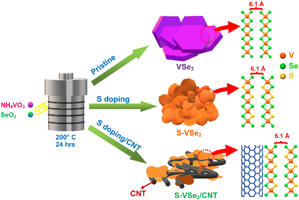
The synthesis route of VSe2, S-doped VSe2 (S-VSe2) and S-VSe2/CNT is depicted in Scheme 1, and the detailed synthesis procedure is provided in the ESI.† The carboxyl groups of functionalized CNT can act as nucleation sites that electrostatically absorb V4+ ion from the starting precursor and then culminate in the growth of S-VSe2 sheets on CNT.32,33 Crystalline phase analysis of the synthesised samples was carried out using XRD. XRD patterns of VSe2, S-VSe2 and S-VSe2/CNT (Fig. 1a) show the highly crystalline diffraction pattern of the hexagonal VSe2 phase (JCPDS: 89-1641). The XRD pattern of the S-doped sample agrees well with the undoped VSe2 sample without the formation of any isolated VS2 or VS phases. The intensity of the (00l) c-axis peaks in the S-VSe2 sample is substantially increased compared to that of pristine VSe2. A similar intensity variation can also be observed in the S-VSe2/CNT sample, signifying that this relative intensity variation of the c-axis plane is caused by S doping in the VSe2 lattice. This distinctly enhanced (00l) reflections in the doped samples can be attributed to the formation of multilayer VSe2 nanosheets compared to the bulk macro sheets of pristine VSe2.34,35 A broad reflection in the S-VSe2/CNT from the (002) plane of CNT is observed at ∼26°, confirming the incorporation of CNT. In the diffraction profile of S-VSe2/CNT, small reflections apart from VSe2 and CNT are also observed owing to the presence of minute fractions of V2O5.36,37 Further, the doping effects and hybrid formation in the samples are evaluated using Raman spectroscopy (Fig. 1b). Pristine VSe2 shows a sharp characteristic A1g vibration at 231 cm−1 and small Eg vibration at 137 cm−1.38 The presence of these vibrations can be observed in both S-VSe2 and S-VSe2/CNT confirming the formation of VSe2. In S-VSe2, the Eg vibration is prominently visible probably because of the S-doping-induced VSe2 multilayer nanosheet formation. In the case of S-VSe2/CNT, apart from the A1g and Eg bands of VSe2, the characteristic D and G Raman bands of CNT are observed at 1345 cm−1 and 1595 cm−1, respectively.39 The presence of D and G vibrations explicitly confirms the presence of CNT in the hybrid.
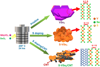 |
| | Scheme 1 Schematic representation of the synthesis of VSe2, S-VSe2 and S-VSe2/CNT. | |
 |
| | Fig. 1 (a) XRD pattern and (b) Raman spectra of VSe2, S-VSe2 and S-VSe2/CNT; high-resolution XPS spectra of (c) V 2p, (d) Se 3d, (e) S 2p and (f) C 1s in S-VSe2/CNT sample. | |
XPS is implemented to study the chemical state and composition of the S-VSe2/CNT sample. The XPS survey provided in Fig. S1 (ESI†) shows the presence of V 2p, Se 3d, S 2p and C 1s signals. The high-resolution V 2p spectra show two peaks corresponding to the V 2p3/2 and V 2p1/2 states (Fig. 1c). The V p3/2 peak is deconvoluted into two peaks located at 516.5 eV and 517.6 eV, and the V 2p1/2 peak is deconvoluted into two peaks at 523.8 eV and 525.1 eV. In particular, peaks at 516.5 eV and 523.8 eV correspond to the V4+ state confirming the presence of VSe2 formation.8,12,38 The peaks at 517.6 eV and 525.1 eV represent the V5+ state of V, showing the presence of V2O5 formation during the CNT hybrid synthesis.36
The deconvoluted Se 3d spectrum shows two peaks at 54.7 eV (Se 3d5/2) and 55.8 eV (Se 3d3/2) attributed to the V–Se bonding in VSe2 crystal (Fig. 1d).40Fig. 1e shows the high-resolution S 2p spectrum deconvoluted into two peaks at 161.1 eV and 162.08 eV corresponding to S 2p3/2 and S 2p1/2 states of S2− ions.24,41,42 These results imply the substitutional S doping by replacing Se atoms in the VSe2 lattice. A broad peak observed at 167.28 eV corresponds to the formation of SO2 after the surface oxidation of the S-VSe2/CNT sample.24,41 The C 1s core level spectrum shows an intense peak at 284.4 eV due to the sp2 hybridized graphitic carbon atoms, which double down the presence of CNT; peak 285.5 eV can be attributed to C–O bond formation due to the presence of phenols or ether (Fig. 1f).33 The oxygenated species of vanadium and carbon can cause the origin of the interfacial binding of S-VSe2 and CNT during the hybrid formation.43
FESEM analysis reveals the morphologies of the synthesized samples. Pristine VSe2 exhibits a large hexagonal sheet morphology similar to previous reports (Fig. 2a and b). After S doping, a significant change is observed in the morphology of VSe2. The S-VSe2 samples show a nanoflower type of morphology with each flower comprising thin S-VSe2 nanosheets (Fig. 2c and d). Compared to the bulk VSe2, this nanoflower in S-VSe2 exposes many electrochemical active centres that eventually enhance the adsorption rate and energy storage performance. In the case of S-VSe2/CNT, it can be observed that the S-VSe2 nanosheets were anchored by the multiwalled CNT (Fig. 2e and f). This interconnected network of CNT and S-VSe2 nanosheets provides more active centres and short diffusion pathways for ions that enhance the electrochemical performance of the S-VSe2/CNT sample. Fig. 2g depicts the EDS elementary mapping of S-VSe2/CNT showing the uniform distribution of V, Se, and C in the sample, confirming homogeneity.
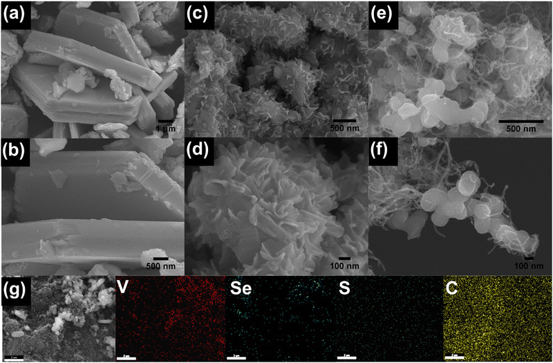 |
| | Fig. 2 Low and high magnified FESEM images of (a and b) VSe2, (c and d) S-VSe2, (e and f) S-VSe2/CNT and (g) EDS elemental mapping of S-VSe2/CNT sample showing the uniform distribution of V, Se, S, and C. | |
2.2 Electrochemical Assessment of S-VSe2/CNT
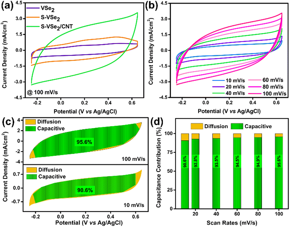
Electrochemical analysis of VSe2, S-VSe2 and S-VSe2/CNT is studied in a conventional three-electrode setup with a glassy carbon working electrode and a 0.5 M K2SO4 aqueous electrolyte. All the electrodes are assessed in a potential window ranging from −0.25 to 0.65 V. Pristine VSe2 shows a quasi-rectangular CV shape, which indicates the pseudocapacitor behaviour of the electrode. The broad redox peaks in the cyclic voltammogram suggest a possible intercalation of the K+ ions during the electrochemical reactions (Fig. S2a, ESI†).5,12Fig. 3a illustrates S-VSe2 with a significant enhancement in current response and enclosed CV area compared to pristine VSe2. This clearly suggests that S doping triggered a substantial enhancement in energy storage performance in VSe2. The electrochemical performance of pristine VSe2 and S-VSe2 is illustrated in Fig. S2 (ESI†). Similarly, the addition of CNT into S-VSe2 has further exceeded the energy storage performance (Fig. 3a). The CV performance of S-VSe2/CNT at various scan rates is shown in Fig. 3b. The CV shape of the S-VSe2/CNT electrode reflects the signatures of an EDLC behavior, which are obviously contributed by the presence of CNT in the sample. During all scan rates, S-VSe2/CNT electrode maintained a similar CV shape that indicates the reversibility of the electrode during the electrochemical activity. To confirm the cation contribution, we tested S-VSe2/CNT electrode in KCl; in both cases, the electrode retained a similar CV shape. This confirms the dominance of cation contribution in pseudocapacitive activity (Fig. S3, ESI†).
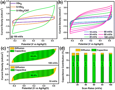 |
| | Fig. 3 Electrochemical measurements of VSe2, S-VSe2 and S-VSe2/CNT electrodes in 0.5 M K2SO4. (a) CV profile of VSe2, S-VSe2 and S-VSe2/CNT at a scan rate of 100 mV s−1, (b) CV profile of S-VSe2/CNT in scan rates ranging from 10 mV s−1 to 100 mV s−1, (c) segregated CV curves of S-VSe2/CNT into capacitive and diffusive regions at selected scan rates and (d) normalized capacitive and diffusive contribution in all the scan rates. | |
To understand the charge storage mechanism in S-VSe2/CNT electrode, we have the induced power law i = aνb in the CV curve, where i is the current response at a specific potential, a and b are the adjustable parameters, and ν is the scan rate.44 Generally, if b = 1, then the mechanism is dominated by capacitive contribution, and if b = ½, then the mechanism is dominated by diffusion reactions. The power law can be rewritten as follows:44
or
| | | i(V)/ν1/2 = k1ν1/2 + k2. | (2) |
By calculating
k1 and
k2, the CV profiles can be deconvoluted into capacitive and diffusive contributions. The deconvoluted CV profile of S-VSe
2/CNT shows complete domination of capacitive behaviour over diffusion.
Fig. 3c shows the segregation of capacitive and diffusive contributions at lower and higher scan rates. At a lower scan rate of 10 mV s
−1, the capacitive contribution is 90.6%, which clearly suggests that the electrochemical mechanism is dominated by capacitive contributions obtained from the intercalation pseudocapacitance of S-VSe
2 and the EDLC of CNT. The power law-induced deconvolution is performed at all scan rates, and the results are shown in
Fig. 3d. The electrochemical reactions in VSe
2 involve fast K
+ ion accessibility, which can be represented as follows:
45| | | VSe2 + K+e− ↔ VSe − KSe, | (3) |
| | | (VSe2)surface + K+ + e− ↔ (VSe2− − K+)surface. | (4) |
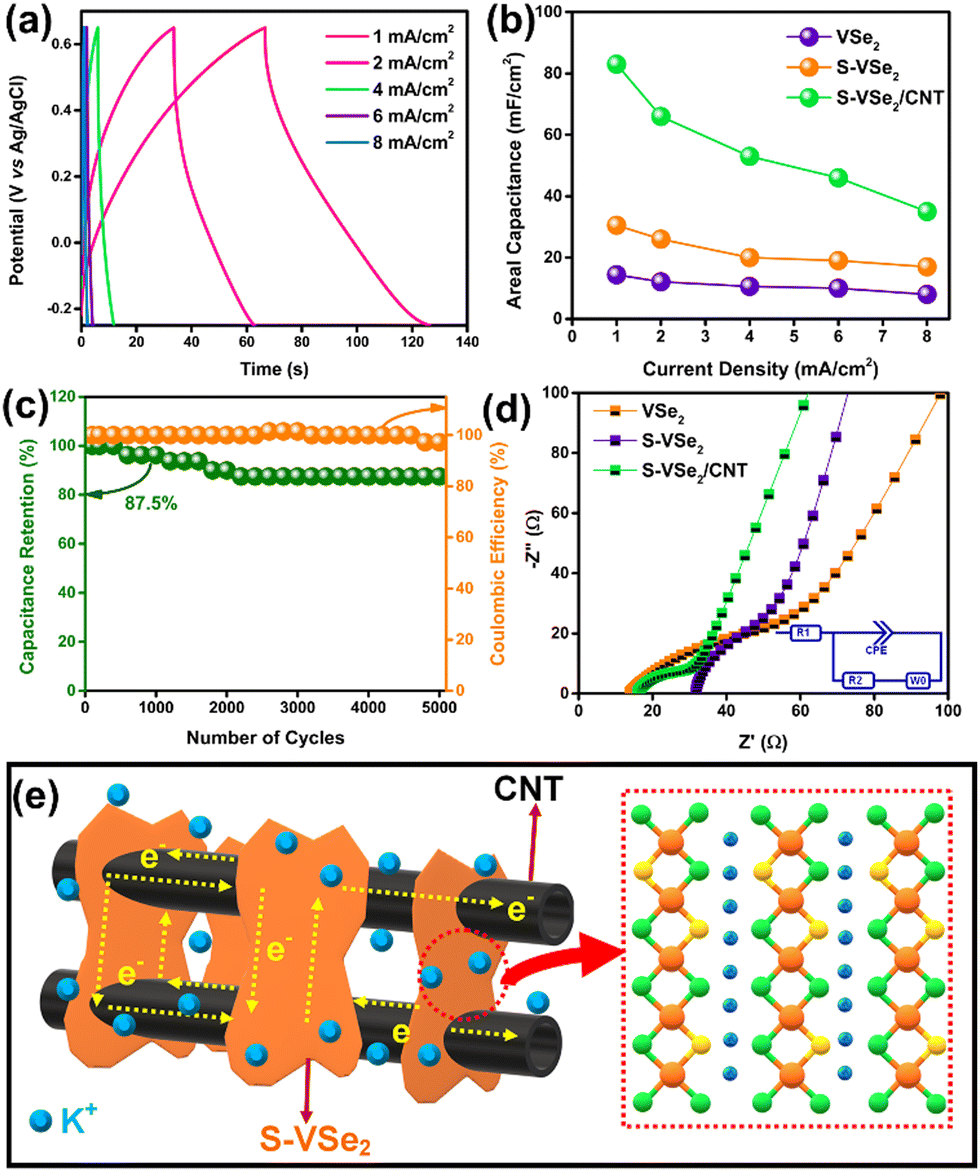
The GCD curves of S-VSe2/CNT show a quasi-triangular shape without any potential independent region in current densities ranging from 1 to 8 mA cm−2 (Fig. 4a). Further, the GCD curve limits the IR drop and exhibits excellent coulombic efficiency, corroborating the reversible electrochemical reactions involved with the S-VSe2/CNT electrode. Areal capacitance as a function of current density for VSe2, S-VSe2 and S-VSe2/CNT is illustrated in Fig. 4b. S doping increased the areal capacitance of S-VSe2 more than twice that of pristine VSe2. The addition of CNT further enhanced the areal capacitance to 83 mF cm−2, which is a significant enhancement from S-VSe2. The enhancement in the capacitance value of the S-VSe2/CNT electrode can be attributed to the synergistic effect between S-VSe2 and CNT. Cyclic stability is one of the most important factors in analysing the performance of supercapacitor electrodes. S-VSe2/CNT exhibited a capacitance retention of 87.5% after 5000 charge/discharge cycles with a coulombic efficiency of more than 97% (Fig. 4c). High capacitance retention and coulombic efficiency indicate excellent electrochemical stability and reversibility of the S-VSe2/CNT electrode. The kinetics of the electrochemical reactions of all the samples are analysed using EIS (Fig. 4d). The intersection at the high-frequency region is usually considered the intrinsic resistance of the electrode (Rs), and the diameter of the semi-circular region at the mid-high-frequency region represents the charge transfer resistance (Rct). The Nyquist plot reveals that S doping reduced charge transfer resistance of VSe2, which emphasises the enhanced electrochemical performance in S-VSe2.46 After the addition of CNT, the Rct value further decreased significantly. This correlates with the excellent charge storage performance of the electrode.14 Pristine VSe2 shows a low Rs value owing to its inherent metallic nature. An increase in the Rs value of the S-VSe2 sample is due to an altered electronic atmosphere after the doping of a non-metal. The addition of highly conducting CNT reduces the Rs value, which clearly affects the charge storage performance of the S-VSe2/CNT electrode. Rs and Rct values of all the samples are provided in Table S1 (ESI†). The diffusion-controlled high-frequency region of the S-VSe2/CNT electrode exhibits capacitor-type behaviour correlating with results obtained after the deconvolution of CV.
 |
| | Fig. 4 (a) GCD curves of S-VSe2/CNT electrode in various current densities, (b) areal capacitances of VSe2, S-VSe2 and S-VSe2/CNT plotted against corresponding current densities, (c) cyclic performance of S-VSe2/CNT during 5000 cycles at a current density of 10 mA cm−2, (d) Nyquist plots of VSe2, S-VSe2 and S-VSe2/CNT and (e) schematic illustration of the possible charge storage mechanism in S-VSe2/CNT electrode involving intercalation of K+ ions in S-VSe2 sheets. | |
S doping alters the electronic atmosphere inside the VSe2 lattice and provides better electronic conductivity.23,42 The formation of the nanoflower morphology of VSe2 after S doping improves the electrode/electrolyte contact area, and the increased number of active sites can enhance the rate of electrochemical reactions.47 CNT addition provides further improvement in electrochemical performance owing to the synergistic effect between S-VSe2 and CNT.48 The presence of CNT facilitates the accommodation of more electrolyte ions, and this enhances the electrochemical reactions. The highly conducting CNT network decreases ionic and electronic pathways between S-VSe2 nano sheets and fastens the rate of electrochemical reactions. CNT acts as a conductive skeleton and provides excellent electrochemical stability to S-VSe2.49 This hybrid architecture of S-VSe2/CNT prevents the volume expansion and restacking of S-VSe2 layers during K+ intercalation and deintercalation. The plausible charge storage mechanism of the S-VSe2/CNT electrode is schematically depicted in Fig. 4e.
2.3 Material Characterization of the BCN
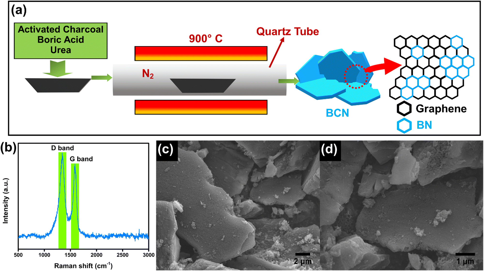
The synthesis procedure of the BCN nanosheets is schematically illustrated in Fig. 5a. The structural characteristics of the prepared BCN are analysed using XRD. The XRD pattern of the BCN shows characteristic peaks of the (002) and (100) planes located at 25.8° and 42.7°, respectively (Fig. S3a, ESI†). The broadening of the (002) peak indicates the formation of few-layer thick BCN sheets.30 Raman spectra show two distinct peaks at 1349 and 1596 cm−1, respectively (Fig. 5b), corresponding to in-plane B–N vibrations and graphitic D bands.27,30 Moreover, the peak observed at 1596 cm−1 (G band) is attributed to the sp2-bonded carbon atoms of the graphene domains. FESEM images of the prepared BCN are provided in Fig. 5c and d. The BCN shows a sheet-like morphology with porous structures on the surface. This porous sheet-like morphology enhances electrochemical adsorption and allows for the use of almost the entire available electrode surface for electrochemical reactions. EDS elemental mapping is provided in Fig. S4e (ESI†), showing a uniform distribution of B, C and N in the BCN sample. XPS analysis was implemented to understand the elemental composition of the BCN sample. The high-resolution B 1s spectrum provided in Fig. S4b (ESI†) depicts two distinct peaks located at 190.9 and 192.0 eV corresponding to B–C and B–N bonds. The C 1s spectrum of BCN was deconvoluted into three peaks at 283.8, 284.5 and 285.4 eV, representing C–B, C–C and C–N bonds, respectively (Fig. S4c, ESI†). The deconvoluted N 1s spectrum shows N–B and N–C bonding at binding energies of 398.4 and 400.1 eV, respectively (Fig. S4d, ESI†).31
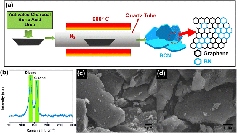 |
| | Fig. 5 (a) Schematic illustration of the synthesis of BCN sheets using urea route, (b) Raman spectrum of BCN, (c and d) FESEM images showing the porous sheet like morphology of BCN. | |
2.4 Electrochemical assessment of BCN
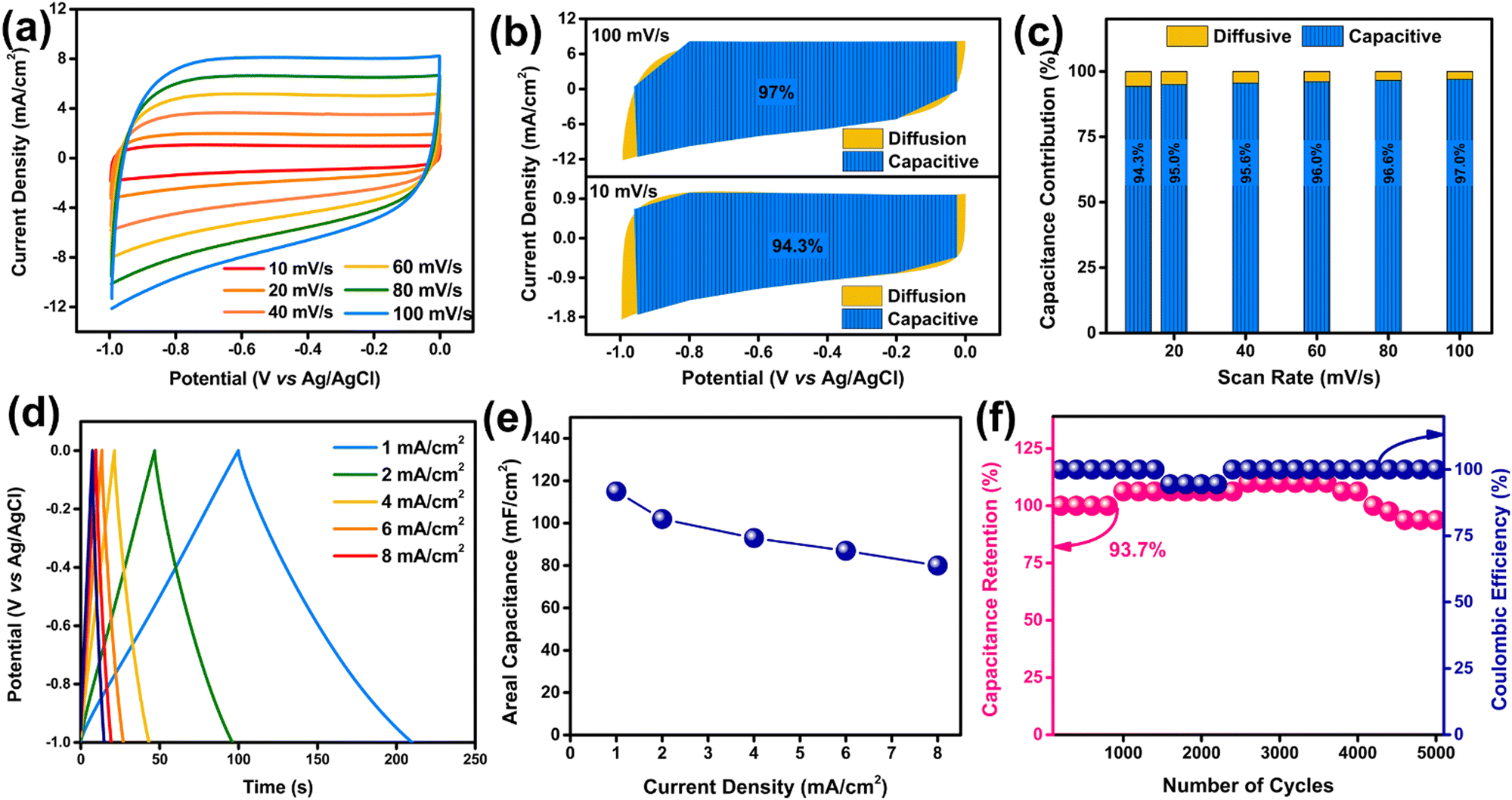
Similar to S-VSe2/CNT, the electrochemical performance of BCN is also analyzed in a 0.5 M K2SO4 electrolyte by employing a three-electrode cell. A cyclic voltammogram of BCN shows neat EDLC behaviour in a potential window of −1.0 to 0.0 V (Fig. 6a). From a lower scan rate to a higher scan rate, the BCN electrode maintained a rectangular shape without any deformation, showing excellent reversibility during electrochemical reactions. To further understand the charge storage mechanism of BCN, we segregated CV curves into capacitive and diffusive contributions using power law. The segregated CV profile of the BCN shows a complete dominance of capacitive contribution over diffusion due to the EDLC mechanism of the electrode. The capacitive contribution of the BCN electrode increases from 94.3% at 10 mV s−1 to 97% at 100 mV s−1 (Fig. 6b and c). Dominant capacitive performance is beneficial for the BCN electrode in terms of excellent cyclic stability and high-rate performance.
 |
| | Fig. 6 Electrochemical measurements of BCN sheets in 0.5 M K2SO4. (a) CV profile of BCN in scan rates ranging from 10 mV s−1 to 100 mV s−1, (b) segregated CV curves of BCN into capacitive and diffusive regions at selected scan rates, (c) normalized capacitive and diffusive contributions in all the scan rates, (d) GCD curves of BCN in various current densities, (e) areal capacitance of BCN plotted against corresponding current densities and (f) cyclic performance of BCN electrode during 5000 cycles at a current density of 10 mA cm−2. | |
The GCD curves of the BCN electrode exhibited a nearly triangular shape based on the EDLC behaviour (Fig. 6d). The linear charge/discharge curves in current densities ranging from 1 to 8 mA cm−2 suggest the excellent capacitive behaviour of the BCN electrode. The areal capacitance of the BCN electrode calculated from the GCD is shown in Fig. 6e. The BCN attained an areal capacitance of 115 mF cm−2 at a current density of 1 mA cm−2, and the electrode showed a great rate capability by retaining almost 69% of its initial capacitance after an eight-fold increment in current density. The cyclic stability of BCN is measured, and the electrode exhibited a 93.7% capacitance retention after 5000 GCD cycles (Fig. 6f). During the cyclic study, we observed that the capacitance value exceeded 100% and decreased after reaching the maximum value. The increase in capacitance is quite obvious in porous materials owing to the entrapment of ions inside the pores and the enhancement of pore size during long-cycle operation.50,51 BCN showed near 100% coulombic efficiency during the cyclic study, which emphasises the high reversibility and exceptional electrochemical stability of the BCN electrode. The Nyquist plot of BCN reveals a capacitor-type behaviour with an Rct value of 6.2 Ω (Fig. S5, ESI†).
2.5 Performance of S-VSe2/CNT//BCN asymmetric supercapacitor
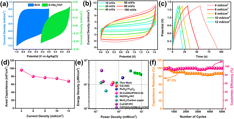
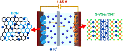
To evaluate the practical application of S-VSe2/CNT and BCN, an asymmetric supercapacitor (ASC) was constructed with S-VSe2/CNT as the positrode and BCN as the negatrode (Fig. 7a). Before assembling, mass balance theory was implemented to attain the charge balance in both electrodes, i.e., m−/m+ = 0.64. The potential stability of S-VSe2/CNT//BCN ASC is studied at various potential windows, and the optimized working window of the device is set at 1.65 V (Fig. S6a, ESI†). The CV curve of ASC is analogous to that of S-VSe2/CNT and BCN, showing that the working mechanism of ASC is an admixture of pseudocapacitance and EDLC (Fig. 7b). During all the scan rates of the ASC, no considerable distortions are observed in the CV shape, signifying the excellent capacitive behaviour of the device. The GCD profiles of the S-VSe2/CNT//BCN ASC show a near-symmetric shape without any plateaus, signalling the absence of diffusive contributions (Fig. 7c). The areal capacitance obtained from the GCD profiles of ASC is provided in Fig. 7d. The ASC delivered a high areal capacitance of 96 mF cm−2 at a current density of 4 mA cm−2 and retained 68 mF cm−2 of its initial capacitance at a high current density of 12 mA cm−2, exhibiting the high-rate capability of the device. The Ragone plot is important for evaluating the energy storage capability of a full cell. S-VSe2/CNT//BCN ASC achieved a high energy density of 36.3 μW h cm−2 at a power density of 3.2 mW cm−2, and the ASC retained 70% of the initial energy density at a large power density of 9.2 mW cm−2 (Fig. 7e). The energy storage performance of S-VSe2/CNT//BCN ASC is comparable to many recently reported values52–59 (Table S2, ESI†). Fig. 7f illustrates the cyclic performance of ASC, exhibiting an 87.2% capacitance retention after 5000 charge/discharge cycles performed at a current density of 15 mA cm−2 with a coulombic efficiency of more than 96%. Comparing the Nyquist plots of the ASC before and after stability, no considerable deviations in their shape were observed (Fig. S6b, ESI†). This corresponds to the electrochemical stability of the full cell. The working mechanism of S-VSe2/CNT//BCN ASC is illustrated in Scheme 2.
 |
| | Fig. 7 Electrochemical performance of S-VSe2/CNT//BCN asymmetric supercapacitor. (a) CV curves of S-VSe2/CNT and BCN at 100 mV s−1, (b) CV profile of S-VSe2/CNT//BCN ASC in scan rates ranging from 10 mV s−1 to 100 mV s−1, (c) GCD curves of S-VSe2/CNT//BCN ASC in various current densities, (d) areal capacitance of the ASC plotted against current densities, (e) the Ragone plot of S-VSe2/CNT//BCN ASC compared with reported ASCs and (f) cyclic performance of S-VSe2/CNT//BCN ASC during 5000 cycles at 15 mA cm−2. | |
 |
| | Scheme 2 Schematic representation of the working of S-VSe2/CNT//BCN ASC. | |
3. Conclusions
In summary, S-doped VSe2/CNT is successfully synthesized using a facile hydrothermal method. By applying sophisticated characterization techniques, the effects of S doping and CNT hybrid formation in VSe2 are analysed. The substitutional doping of S atoms in the VSe2 lattice can provide a considerable improvement in the charge storage capability of S-VSe2, but this improvement is limited to a certain extent. The S-VSe2/CNT hybrid as a positrode conferred excellent charge storage capabilities with remarkable cyclic stability compared to S-VSe2 and pristine VSe2. The enhanced electrochemical activity of S-VSe2/CNT can be attributed to the synergistic effect between S-VSe2 and CNT. BCN, an intriguing layered 2D material with EDLC behaviour prepared via a solid-state urea route, was electrochemically analysed as a negatrode. The material and electrochemical characterization provide insight into the chemical structure of BCN and its prodigious charge storage capability. An asymmetric supercapacitor was constructed with S-VSe2/CNT and BCN, showing exceptional energy density and power density along with long cycle life. The VSe2/CNT//BCN ASC inherits all the individual advantages of each electrode material to deliver a promising ASC for next-generation energy storage applications.
Conflicts of interest
The authors declare no conflict of interest.
Acknowledgements
The financial support for this work is provided by the Department of Science and Technology (DST)-SERB Early Career Research project (Grant No. ECR/2017/001850), DST-Nanomission (DST/NM/NT/2019/205(G)), Karnataka Science and Technology Promotion Society (KSTePS/VGST-RGS-F/2018-19/GRD NO. 829/315).
References
- Y. Gogotsi and P. Simon, Science, 2011, 334, 917–918 CrossRef CAS PubMed.
- P. Simonand and Y. Gogotsi, Nat. Mater., 2008, 7, 845–854 CrossRef PubMed.
- C. Costentin, T. R. Porter and J. M. Savéant, ACS Appl. Mater. Interfaces, 2017, 9, 8649–8658 CrossRef CAS PubMed.
- Y. Jiang and J. Liu, Energy Environ. Mater., 2019, 2, 30–37 CrossRef.
- Y. Shao, M. F. El-Kady, J. Sun, Y. Li, Q. Zhang, M. Zhu, H. Wang, B. Dunn and R. B. Kaner, Chem. Rev., 2018, 118, 9233–9280 CrossRef CAS PubMed.
- S. Manzeli, D. Ovchinnikov, D. Pasquier, O. V. Yazyev and A. Kis, Nat. Rev. Mater., 2017, 2, 1–15 Search PubMed.
- R. Lv, J. A. Robinson, R. E. Schaak, D. Sun, Y. Sun, T. E. Mallouk and M. Terrones, Acc. Chem. Res., 2015, 48, 56–64 CrossRef CAS PubMed.
- L. Wang, Z. Wu, M. Jiang, J. Lu, Q. Huang, Y. Zhang, L. Fu, M. Wu and Y. Wu, J. Mater. Chem. A, 2020, 8, 9313–9321 RSC.
- H. Lei, M. Wang, J. Tu and S. Jiao, Sustainable Energy Fuels, 2019, 3, 2717–2724 RSC.
- X. Wu, Z. B. Zhai, K. J. Huang, R. R. Ren and F. Wang, J. Power Sources, 2020, 448, 1–7 CrossRef.
- D. Li, X. Wang, C. M. Kan, D. He, Z. Li, Q. Hao, H. Zhao, C. Wu, C. Jin and X. Cui, ACS Appl. Mater. Interfaces, 2020, 12, 25143–25149 CrossRef CAS PubMed.
- C. Yang, J. Feng, F. Lv, J. Zhou, C. Lin, K. Wang, Y. Zhang, Y. Yang, W. Wang, J. Li and S. Guo, Adv. Mater., 2018, 30, 1–8 Search PubMed.
- K. A. Sree Raj, A. S. Shajahan, B. Chakraborty and C. S. Rout, RSC Adv., 2020, 10, 31712–31719 RSC.
- K. A. Sree Raj, A. S. Shajahan, B. Chakraborty and C. S. Rout, Chem. – Eur. J., 2020, 26, 6662–6669 CrossRef CAS PubMed.
- S. R. Marri, S. Ratha, C. S. Rout and J. N. Behera, Chem. Commun., 2017, 53, 228–231 RSC.
- S. P. Gupta, B. A. Kakade, B. R. Sathe, Q. Qiao, D. J. Late and P. S. Walke, ACS Appl. Energy Mater., 2020, 3, 11398–11409 CrossRef CAS.
- S. P. Gupta, S. W. Gosavi, D. J. Late, Q. Qiao and P. S. Walke, Electrochim. Acta, 2020, 354, 136626 CrossRef CAS.
- S. P. Gupta, A. R. Shakeelur Raheman, A. Gurung, Q. Qiao, D. J. Late and P. S. Walke, Carbon N. Y., 2022, 192, 153–161 CrossRef CAS.
- H. Peng, C. Wei, K. Wang, T. Meng, G. Ma, Z. Lei and X. Gong, ACS Appl. Mater. Interfaces, 2017, 9, 17067–17075 CrossRef CAS PubMed.
- X. Xu, Y. Ge, M. Wang, Z. Zhang, P. Dong, R. Baines, M. Ye and J. Shen, ACS Appl. Mater. Interfaces, 2016, 8, 18036–18042 CrossRef CAS PubMed.
- H. Jia, C. Chen, O. Oladele, Y. Tang, G. Li, X. Zhang and F. Yan, Commun. Chem., 2018, 1, 1–12 CrossRef CAS.
- W. Xu, J. Chen, M. Yu, Y. Zeng, Y. Long, X. Lu and Y. Tong, J. Mater. Chem. A, 2016, 4, 10779–10785 RSC.
- W. Fan, D. Wang, Z. Sun, X. Y. Ling and T. Liu, Inorg. Chem. Front., 2019, 6, 1209–1216 RSC.
- X. Fang, Z. Wang, Z. Jiang, J. Wang and M. Dong, Electrochim. Acta, 2019, 322, 134739 CrossRef CAS.
- Z. Shi, J. Zhu, Z. Li, Q. Xiao and J. Zhu, ACS Appl. Energy Mater., 2020, 3, 11082–11090 CrossRef CAS.
- L. Xu, X. Zhou, X. Xu, L. Ma, J. Luo and L. Zhang, Adv. Powder Technol., 2016, 27, 1560–1567 CrossRef CAS.
- C. N. R. Rao and K. Pramoda, Bull. Chem. Soc. Jpn., 2019, 92, 441–468 CrossRef CAS.
- S. Angizi, M. A. Akbar, M. Darestani-Farahani and P. Kruse, ECS J. Solid State Sci. Technol., 2020, 9, 083004 CrossRef CAS.
- K. Pramoda, M. M. Ayyub, N. K. Singh, M. Chhetri, U. Gupta, A. Soni and C. N. R. Rao, J. Phys. Chem. C, 2018, 122, 13376–13384 CrossRef CAS.
- N. Kumar, K. Moses, K. Pramoda, S. N. Shirodkar, A. K. Mishra, U. V. Waghmare, A. Sundaresan and C. N. R. Rao, J. Mater. Chem. A, 2013, 1, 5806–5821 RSC.
- I. Karbhal, A. Basu, A. Patrike and M. V. Shelke, Carbon N. Y., 2021, 171, 750–757 CrossRef CAS.
- B. Pandit, S. S. Karade and B. R. Sankapal, ACS Appl. Mater. Interfaces, 2017, 9, 44880–44891 CrossRef CAS PubMed.
- M. Sathiya, A. S. Prakash, K. Ramesha, J. M. Tarascon and A. K. Shukla, J. Am. Chem. Soc., 2011, 133, 16291–16299 CrossRef CAS PubMed.
- K. Xu, P. Chen, X. Li, C. Wu, Y. Guo, J. Zhao, X. Wu and Y. Xie, Angew. Chem., Int. Ed., 2013, 52, 10477–10481 CrossRef CAS PubMed.
- H. Lin, S. He, Z. Mao, J. Miao, M. Xu and Q. Li, Nanotechnology, 2017, 28, 0–16 Search PubMed.
- G. Sun, H. Ren, Z. Shi, L. Zhang, Z. Wang, K. Zhan, Y. Yan, J. Yang and B. Zhao, J. Colloid Interface Sci., 2021, 588, 847–856 CrossRef CAS PubMed.
- J. Qi, T. Wu, M. Xu and Z. Xiao, ACS Appl. Mater. Interfaces, 2021, 13, 39186–39194 CrossRef CAS PubMed.
- F. Ming, H. Liang, Y. Lei, W. Zhang and H. N. Alshareef, Nano Energy, 2018, 53, 11–16 CrossRef CAS.
- M. S. Dresselhaus, A. Jorio, M. Hofmann, G. Dresselhaus and R. Saito, Nano Lett., 2010, 10, 751–758 CrossRef CAS PubMed.
- Q. Zhu, M. Shao, S. H. Yu, X. Wang, Z. Tang, B. Chen, H. Cheng, Z. Lu, D. Chua and H. Pan, ACS Appl. Energy Mater., 2019, 2, 644–653 CrossRef CAS.
- N. Xue, Z. Lin, P. Li, P. Diao and Q. Zhang, ACS Appl. Mater. Interfaces, 2020, 12, 28288–28297 CrossRef CAS PubMed.
- Y. Yang, S. Wang, J. Zhang, H. Li, Z. Tang and X. Wang, Inorg. Chem. Front., 2015, 2, 931–937 RSC.
- H. Huang, W. Huang, Z. Yang, J. Huang, J. Lin, W. Liu and Y. Liu, J. Mater. Chem. A, 2017, 5, 1558–1566 RSC.
- Q. Jiang, N. Kurra, M. Alhabeb, Y. Gogotsi and H. N. Alshareef, Adv. Energy Mater., 2018, 8, 1–10 Search PubMed.
- K. A. Sree Raj, P. Mane, S. Radhakrishnan, B. Chakraborty and C. S. Rout, ACS Appl. Nano Mater., 2022, 5, 4423–4436 CrossRef.
- K. A. Sree Raj, S. Adhikari, S. Radhakrishnan, P. Johari and C. S. Rout, Nanotechnology, 2022, 33, 295703 CrossRef PubMed.
- S. Xie, J. Gou, B. Liu and C. Liu, Inorg. Chem. Front., 2018, 5, 1218–1225 RSC.
- B. Pandit, S. S. Karade and B. R. Sankapal, ACS Appl. Mater. Interfaces, 2017, 9, 44880–44891 CrossRef CAS PubMed.
- W. Zhang, B. Zhao, Y. Yin, T. Yin, J. Cheng, K. Zhan, Y. Yan, J. Yang and J. Li, J. Mater. Chem. A, 2016, 4, 19026–19036 RSC.
- Y. Luo, C. Yang, Y. Tian, Y. Tang, X. Yin and W. Que, J. Power Sources, 2020, 450, 227694 CrossRef CAS.
- S. Liu, D. Ni, H. F. Li, K. N. Hui, C. Y. Ouyang and S. C. Jun, J. Mater. Chem. A, 2018, 6, 10674–10685 RSC.
- S. C. Lee, U. M. Patil, S. J. Kim, S. Ahn, S. W. Kang and S. C. Jun, RSC Adv., 2016, 6, 43844–43854 RSC.
- L. Gao, J. U. Surjadi, K. Cao, H. Zhang, P. Li, S. Xu, C. Jiang, J. Song, D. Sun and Y. Lu, ACS Appl. Mater. Interfaces, 2017, 9, 5409–5418 CrossRef CAS PubMed.
- S. T. Senthilkumar and R. Kalai Selvan, Phys. Chem. Chem. Phys., 2014, 16, 15692–15698 RSC.
- H. Xu, X. Hu, Y. Sun, H. Yang, X. Liu and Y. Huang, Nano Res., 2015, 8, 1148–1158 CrossRef CAS.
- S. T. Senthilkumar, J. Kim, Y. Wang, H. Huang and Y. Kim, J. Mater. Chem. A, 2016, 4, 4934–4940 RSC.
- Y. Li, X. Yan, X. Zheng, H. Si, M. Li, Y. Liu, Y. Sun, Y. Jiang and Y. Zhang, J. Mater. Chem. A, 2016, 4, 17704–17710 RSC.
- J. Guo, Y. Zhao, A. Liu and T. Ma, Electrochim. Acta, 2019, 305, 164–174 CrossRef CAS.
- Z. Pan, F. Cao, X. Hu and X. Ji, J. Mater. Chem. A, 2019, 7, 8984–8992 RSC.
|
| This journal is © The Royal Society of Chemistry 2023 |

 *
*