
 Open Access Article
 This Open Access Article is licensed under a
 Creative Commons Attribution 3.0 Unported Licence
Direct observations of electrochemically induced intergranular cracking in polycrystalline NMC811 particles†
Huw C. W.
Parks
ab,
Adam M.
Boyce
ac,
Aaron
Wade
ab,
Thomas M. M.
Heenan
ab,
Chun
Tan
 ab,
Emilio
Martínez-Pañeda
d,
Paul R.
Shearing
abde,
Dan J. L.
Brett
ab and
Rhodri
Jervis
*ab
ab,
Emilio
Martínez-Pañeda
d,
Paul R.
Shearing
abde,
Dan J. L.
Brett
ab and
Rhodri
Jervis
*ab
aElectrochemical Innovation Lab, Department of Chemical Engineering, University College London, London, WC1E 7JE, UK. E-mail: Rhodri.Jervis@ucl.ac.uk
bThe Faraday Institution, Quad One, Harwell Science and Innovation Campus, Didcot, OX11 0RA, UK
cSchool of Mechanical and Materials Engineering, University College Dublin, Dublin D04V1W8, Ireland
dDepartment of Engineering Science, University of Oxford, Oxford OX1 3PJ, UK
eZero Institute Energy Research, Oxford University, Holywell House, Osney Mead, Oxford, OX2 0ES, UK
First published on 18th September 2023
Abstract
Establishing the nature of crack generation, formation, and propagation is paramount to understanding the degradation modes that govern decline in battery performance. Cracking has several possible origins; however, it can be classified in two general cases: mechanically induced, during manufacturing, or electrochemically induced, during operation. Accurate and repeatable tracking of operational cracking to sequentially image the same material as it undergoes cracking is highly challenging; observing these features requires the highest resolutions possible for 3D imaging techniques, necessitating very small sample geometry, while also achieving realistic electrochemical performance. Here, we present a technique in which particle cracking can be completely attributed to electrochemical stimulation via sequential ex situ imaging in a laboratory X-ray nano computed tomography (CT) instrument. This technique preserves the mechanical and electrochemical response of each particle without inducing damage in the particles except for the effects of high voltage. Significant cracking within the core of secondary particles was observed upon the electrochemical delithiation of NMC811, which propagated radially. As X-ray computed tomography allows for imaging of the particle cores, the particles were not required to be modified/milled, guaranteeing any synthesis induced strain in the particles was maintained during the whole technique, resulting in an observation that contrasts crystallographic data, suggesting a significant volume expansion of the secondary particles.
1 Introduction
Decarbonisation of the automotive industry has highlighted battery technologies as a viable successor to petroleum-based travel. With increasing performance of state-of-the-art Li-ion battery materials comes a tendency to initiate degradative mechanisms more rapidly than acceptable for commercially viable products. Even with the greatest gravimetric and volumetric density, promising transition metal (TM) oxide cathode materials can suffer from limited cycle life, high cost, and reduced performance. NMC (Li1[Ni1−x−yMnxCoy]O2) based Li-ion batteries have emerged as the most promising successor to LiCoO2 cathodes and could potentially facilitate ubiquitous adoption of Li-ion in mobile and transport devices.1 High specific capacities, high-rate capability, and long-term cycling abilities are driving extensive research into these cathode materials whilst forcing a higher nickel content with each iteration. The redox capability of nickel makes it highly attractive for Li-ion operation, being able to cycle between Ni(II) and Ni(III) as well as Ni(III) to Ni(IV) without a significant deviation in operational voltage. This has presented as an increase in nickel content to the current NMC811 cathode, which exhibits a specific capacity of 190–220 mA h g−1.2Initial observations of NMC811 by X-ray diffraction show expansion in the c-lattice parameter during charging/delithiation followed by a drastic reduction shortly after 4.1 V vs. Li/Li+, often termed the lattice collapse.2,3 Upwards of 4.1 V, delithiation is significant enough to reduce the interlayer spacing between TM-oxygen layers to less than that of a fully lithiated lattice.2,4 The evolution in the a- and c-lattice parameters coincides with a total unit cell volumetric reduction; during charging, the removal of lithium causes a contraction in the TM–O bond length from 2.87 to 2.81 Å, manifesting in a shrinkage of the a-lattice parameter. This has been reported to be due to charge compensation where Ni(II) oxidises to Ni(IV) and thus has a greater covalent attraction to its surrounding oxygen atoms.2 It is believed that this collapse then requires an additional energetic contribution to intercalate lithium back into the structure, consequently increasing the stress on the lattice.5 These extensive heterogenous volume fluctuations have been suggested as an origin for electrochemically mediated crack formation, as randomly aligned primary crystals expand and contract asymmetrically causing voids between grain boundries.6
Cracking in secondary particles has been suggested to cause reduced performance due to insufficient connection between particles and the conductive architecture in the electrode matrix,7 as well as fresh surface exposure to electrolyte and subsequent oxygen release accompanied by electrolyte oxidation.8 It has been determined that the significant expansion and contraction of the c-lattice parameter during cycling will induce strain on the cathode secondary particles, resulting in the possible development of micro-cracks along primary particles grain boundaries.9 As suggested above, the changes in lattice parameters are likely to be an origin of cracking and can advance degradation severely, especially during fast charge cycles that sees substantial changes in crystallographic parameters in a short space of time.5 Additional investigations have prompted a look at the origins of crack formation, showing that cracks may not be solely mediated by crystallographic activity, and therefore it is vital to the understanding of fracture behaviour to be able to register the initial condition of particles without compromising their mechanical and morphological integrity. Indeed, approximately 1/3 of all particles investigated had fabrication-induced cracking in particles due to physical stresses such as calendaring, winding, or synthesis induced fracturing.10 This also indicated an increased number of particles with larger cracks to be located towards the separator interface before cycling and suggested that any new cracks would be due to heterogeneous lattice activity. This through electrode directionality could be a feature of electrochemically mediated cracking and wrongly correlated if the initial state of the particle is unknown, concluding that electrochemical cracking was oriented in the lithium diffusion vector before characterising the pre-exiting cracks.
Understanding the role and the origins of cracking has become important to help develop preventative measures and prolong lifetime. Studies have attempted to show the propagation of cracks within secondary particles, most commonly utilising destructive focused ion beam scanning electron microscopy (FIB-SEM)11,12 methods or tracking of single particles mounted on a steel pin.13 Whilst these experiments provide good evidence for electrochemically induced cracking, the nature of the cracks presented have little relevance to commercial electrode environments. Using FIB-SEM provides high resolution images of cracks within the particle cores but, due to the particles being cut in half, any residual stresses that are inherent to secondary particles induced by synthesis may be released and thus won't contribute to the cracking phenomenon that may be observed in a whole secondary particle. The behaviour of a particle that has already been damaged by the milling process would presumably be affected and thus give an inaccurate representation of the fracturing that would be primarily caused during delithiation. In addition, a single particle mounted on a pin will not experience any of the external influences from being embedded in the complex electrode matrix, especially the elasticity of the PVDF (polyvinylidene fluoride) binder,14 and the directional lithium flux experienced as a function of co-planar electrode stacking.
Here, we demonstrate, for the first time, a lab-based X-ray tomographic method by which the same particles can be imaged before and after electrochemical testing within a commercially available electrode sheet, and thus the important distinction between mechanically induced cracks and those resulting from electrochemical stimulus can be made without the requirement for hundreds of particles to be processed to obtain satisfactory statistics. Nano X-ray computed tomography (XCT), which preserves the particle structure within an electrode matrix (i.e. is non-destructive), was utilised here with the addition of a specific electrode geometry designed for limited field of view (FoV) imaging techniques. This method can allow for sequential imaging of initially pristine particles within conditions typical of a bulk electrode and thus presents as a commercially relevant system in which to study cracking. Using a lasered micrometer appendage as the electrode geometry, the same particles were able to be located and assessed at pristine and extensively delithiated state, by charging the cell to a high potential. This electrode geometry has been previously adopted as a rapid technique for sample preparation in nano-CT and thus utilised here to gather cracking information from a composite NMC811 electrode as a function of cell potential.15,16
Modelling of the fracture of Li-ion batteries is typically considered at various length scales: the homogenised single particle level,17–22 the agglomerated single particle in 2D23 and 3D,24 and the full electrode level.25 While Allen et al.24 provided insight into the damage behaviour of agglomerate particles at a variety of cycling rates (1C–9C), they did not capture the excessive damage that occurs at low charging rates at high voltages. Here, for the first time to the author's knowledge, we combine X-ray CT imaging and chemomechanical fracture modelling that describes the anisotropic lattice collapse-related mechanism, which leads to cracking at high voltages up to 4.5 V. Furthermore, we employ a phase field method that is mesh objective, overcoming the mesh dependency issues intrinsic to continuum damage models.24
The phase field method permits complex crack patterns in arbitrary geometries to be predicted and has been used in the description of fracture due to hydrogen embrittlement in oil and gas pipelines,26 as well as fracture in materials for nuclear reactors27 and in shape memory alloys.28 Phase field calculations that consider intra- and intergranular cracking have been carried out on NMC811 particles before, these have been on 2D idealised particles by Singh A. and Pal S.,23 Here, we have presented interfacial calculations on realistic 3D particles that move a step beyond this and we present its use in capturing the intergranular, high voltage cracking of a 3D X-ray CT image-based agglomerate particle, while comparing the damage induced in the same particle before and after charging; this is the first time that such calculations have been carried out.
2 Materials and methods
2.1 Electrode preparation
Commercial electrode sheets (NEI Corporation) composed of active material (NMC811, Targray) dispersed within a carbon–binder–domain (CBD), of composition 90![[thin space (1/6-em)]](https://www.rsc.org/images/entities/char_2009.gif) :5:5 wt% NMC811, conductive carbon: and polyvinylidene difluoride (PVDF), respectively. These sheets were printed with an areal capacity of 2.2 mA h cm−2 with an approximate electrode thickness of 69 μm and calendared to porosity of approximately 30%, creating an active material density of 11.36 mg cm−2. The electrode sheets were fixed to a translation table of a laser micro-machining instrument (A Series, Oxford Lasers) containing a 532 nm laser and a spot size of 40 μm. The laser cut a series of lines resulting in an electrode that was 4.0 mm × 4.5 mm (w × h) with an 80 μm × 250 μm tab protrusion from the top (see Fig. S5† for electrode geometry). This tab was used for imaging as demonstrated previously.29
:5:5 wt% NMC811, conductive carbon: and polyvinylidene difluoride (PVDF), respectively. These sheets were printed with an areal capacity of 2.2 mA h cm−2 with an approximate electrode thickness of 69 μm and calendared to porosity of approximately 30%, creating an active material density of 11.36 mg cm−2. The electrode sheets were fixed to a translation table of a laser micro-machining instrument (A Series, Oxford Lasers) containing a 532 nm laser and a spot size of 40 μm. The laser cut a series of lines resulting in an electrode that was 4.0 mm × 4.5 mm (w × h) with an 80 μm × 250 μm tab protrusion from the top (see Fig. S5† for electrode geometry). This tab was used for imaging as demonstrated previously.29
2.2 Nano-CT imaging
Using a specifically designed holder for the electrode which held the tab still and perpendicular to the beam, the sample was loaded into a lab-based nano-CT instrument (Zeiss Xradia 810, Carl Zeiss). The instrument uses a rotating chromium source and employs a quasi-monochromatic 5.4 keV, parallel-beam geometry coupled to a Fresnel zone plate focusing architecture. Images were taken with a pixel binning of 2, leading to an approximate pixel size of 124 nm. Radiographs were taken for 15–30 seconds to produce average detector counts of 2500 over a 64 μm × 64 μm field of view (FoV). For each scan two separate FoV regions were taken, one at the current collector interface and one at the separator interface, with approximately 50% overlap in the middle to aid in post-processing and stitching (see Fig. S5†), allowing for imaging of the entire electrode thickness. Each tomography was comprised of 1601 projections, meaning total scan time was approximately 24 hours including reference images and motor movements. Regions of interest were noted and then located again for subsequent imaging.2.3 Cell assembly/disassembly
After pristine imaging, the electrode was then dried in a glass vacuum oven (Buchi, Germany) at 100 °C overnight before being transferred into an argon filled glove box and built into a standard 2032CR coin cell (Hosen, UK) against a lithium chip (Goodfellows, UK), with an excess of LiPF6 1 M electrolyte in EC/EMC 3:7, with 2 wt% vinylene carbonate (VC) (Soulbrain MI, UK). A tri-polymer separator (Celgard®2320, USA) was used to electrically isolate the electrodes with a glass fibre spacer employed to keep the separator from touching the laser machined tab reducing particle deposition on to the polymer separator (see Fig. S4† for coin cell assembly). After charging, the cell was then disassembled in an argon filled glovebox and left to dry before being added into the custom-made electrode holder. Storage of the electrode was maintained in the glovebox until ready to image to reduce damage from atmospheric conditions.
2.4 Electrochemical characterisation
The cell was charged using a standard constant-current-constant-voltage (CCCV) protocol on a Biologic BCS-805 cell cycler at room temperature to 4.5 V (vs. Li/Li+) at a c-rate of C/50 based on a calculated theoretical capacity of 0.5 mA h, constant voltage was applied until the current had fallen to C/100, and then the cell was disassembled as detailed above.2.5 Image processing
Image processing was performed in Avizo (V2020.2, Thermo Fisher Scientific) on the reconstructed nano-CT volume. Each state of charge scan consisted of two separate scans taken consecutively and thus horizontally stitched together using an image registration wizard to form the full volume of the electrode thickness. Each particle was extracted individually and segmented based on a thresholding algorithm derived from Otsu's method and adjusted manually to only include voxels within the particle boundary.30 Each particle at both pristine and charged state were then labelled using the label analysis Avizo module which assigns specific values to a binary image. For particle analysis all particles were filled. For crack level analysis the NMC phase was separated from the crack structure using the same thresholding method as before. The cracked phase was binarised and analysed using the label analysis module. Skeletonization was performed using the Auto-Skelton module. This module extracts a 1 voxel centreline of filamentous structures from image data by using an edge erosion algorithm until the centre line is extracted. The voxel skeleton is then converted to a spatial graph object, distance map, and provides local analysis on each segment including estimated volume and path radius.2.6 Model framework
The equations, material parameters, and boundary conditions for the chemomechanical phase field fracture model are outlined in ESI.† The model geometry comprises an NMC811 agglomerate secondary particle with internal randomly generated primary particles. The primary particles were idealised as isotropic and linear elastic with Ep = 150 GPa and Poisson's ratio of νp = 0.3, while the lithiation induced strains were applied in a transversely isotropic manner – a direct consequence of the transversely isotropic lattice constants, εa and εc, as measured by Xu et al.21 The lattice strains were implemented such that their direction was transformed through random angles, representing that of a realistic polycrystalline particle. The carbon binder surrounding the particle is assumed to be a linear elastic, isotropic solid of Young's modulus Ec = 0.3 GPa and Poisson's ratio of νc = 0.3. It is typically a nano-porous solid that provides electronic conduction and structural rigidity, while allowing transport and conduction of lithium ions; thus, we assume that charge transfer reactions are permitted at the particle–binder interface despite the presence of a fully solid computational domain. We employ a single particle model that permits the solution of the interface over-potential and current density, as well as the particle voltage. The interface kinetics take the form of a typical Butler–Volmer type equation, while a simplification is made such that the electrolyte is not considered. This is suitable for calculations that involve low cycling rates, and therefore appropriate here due to the C/50 charging regime employed. Further information can be found on the single particle model in the review of Planella et al.31A phase field formulation was used to describe fracture due to anisotropic lithiation-driven strains. Griffith's thermodynamics-based theory of fracture states that variation of total energy in a solid due to an incremental increase in the crack area is a function of the elastic strain energy density and the energy required to create to new surfaces.32 Here, Griffith's theory was recast in variational form,33,34 such that the unknown crack surface is calculated via a phase field variable, ϕ, which assumes a value of 1 for a fully cracked material point and 0 when the material is uncracked. Furthermore, a damage degradation function g can be defined that enables the diminishing stiffness (E′ = gE) of the material to be quantified, where g = (1 − ϕ)2, and E and E′ are the nominal and effective Young's modulus, respectively. A phase field length scale, l, which characterises the size of the fracture process zone was introduced and provided a relation with the material strength according to the AT2 model.35 In addition, to account for the different fracture energies of grain boundaries and bulk material, we introduce an auxiliary variable γ to characterise the transition between material properties (here fracture toughness) of the primary particles (when γ = 1) and that of the bond between the primary particles (γ = 0).23,36 An additional auxiliary differential equation is solved, giving the distribution of γ, while the function h = (1 − γ)2 defines the diffuse transition between the material properties; the equations, as well as the associated boundary conditions and material properties can be found in the ESI.†
2.7 Numerical methods
The secondary particle with diameter of 14 μm was extracted from the X-ray CT electrode image and then a randomised Voronoi microstructure of 400 primary particles was generated using Rhino Grasshopper, forming the polycrystalline geometry. A shell of diameter 20 μm was placed around the particle that captured the presence of carbon binder. The theoretical framework was implemented in the finite element software COMSOL Multiphysics (v6.0, Sweden) on a 3D tomography-based mesh, as described. The mesh consisted of approximately 4 million elements with 13 million degrees of freedom. The Multifrontal Massively Parallel Sparse Direct Solver (MUMPS) was used to solve the discretised transport, electrode kinetics and deformation kinematics equations in a fully coupled manner. Also, a history field was defined to ensure damage irreversibility.19 Time stepping was handled using 2nd order backward Euler differentiation, whilst a time step sensitivity analysis was carried out.3 Results and discussion
3.1 Nano-CT
X-ray CT has been extensively utilised to image and understand the morphology of polycrystalline NMC811, due to its ability to probe the core of particles with non-destructive interactions.10,15,37–39 We have also shown previously that 4D imaging can be achieved, using sequential imaging of the same region of interest (RoI) during temperature cycling of battery materials.40 Lab based nano-CT was adequate to investigate cracking in the internal structure without imaging induced damage of the sample before subsequent temperature cycles. For this, the sample environment was not suitable for electrochemical control. Further ex situ studies have shown that CT is indeed a viable technique for successfully imaging NMC811 particles and resolving micro-scale fractures within the internal structure.41 Work performed within our group has shown that a relationship between the potential of the positive electrode and the extent of cracking exists, proving that cracking is severe at 4.5 V, whereas the extent of cracking was much less so at lower voltages.42 Whilst extensive research has examined battery electrodes using X-ray CT, due to limitations in sample preparation it has yet to be used to track the condition of cathode particles at this resolution within a composite electrode matrix. Iterations of sample preparation have led to the use of a laser milled tab architecture as detailed in the methods section. This method has been presented as a stand-alone method for rapid CT imaging without the addition of an electrochemical component, as well as in XANES imaging,16,29 and here is employed as a technique to locate particles easily in an environment that is not only designed for limited FoV tomography, but that also allows for suitable electrochemical performance.To assess the cracking response to SoC, an initial scan was taken at a pristine state (i.e. prior to any cycling) to set a baseline for each particle and to determine the extent of cracking innately present within the electrode. As shown in the pristine scan (see Fig. 1a, d and e) the level of cracking is minimal with few particles containing resolvable voids between primary particles. Each particle assessed showed that there was no significant crack detected and a homogenous density was seen through all particles as confirmed by the GReyscale Erosion Algorithm for Tomography algorithm (GREAT) discussed in more detail and shown in Fig. 4c; the full method is described by Wade et al.43 This also allowed for a region of interest (RoI) to be determined and therefore reference particles to be located in the subsequent scan. Once scanned, the electrode was dried and built into a coin cell before charging to 4.5 V at C/50, relating to a delithiation state of greater than 85% according to Märker et al.,2 driving the potential of the electrode beyond the typical point where c-lattice collapse occurs and guarantee significant cracking.12
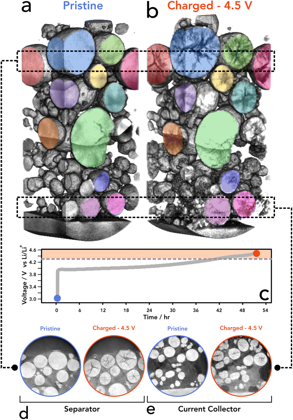 | ||
| Fig. 1 (a and b) Volume rendering of the same region of an NMC811 electrode at (a) blue – pristine and (b) red – charged state (4.5 V s Li/Li+). (c) Charging profile for NMC811 electrode to 4.5 V at C/50, noting potentials at which the two nano-CT datasets were collected. (d and e) Representative ortho slices of the same particles at pristine and charged state at (d) separator and (e) current collector. | ||
The electrode was then imaged for a second time (after disassembly of the coin cell) and the same RoI was located to directly observe any changes induced by charging (delithiation) of the NMC811 particles. As shown in Fig. 1b, d and e, particles that have cracked show a lower attenuation of the X-ray beam in the regions where the cracks reside, due to the lower density/lack of material.37 Since we were tracking individual particles, statistical errors introduced using bulk measurements, where the same particle cannot be examined before and after operation, have been mitigated. In all assessed particles, there was no cracking present prior to charging; consequently, we propose that the crack feature formations were introduced solely by the electrochemical charging conducted and delithiation of the NMC crystallographic structure. To the authors' knowledge, this is the first SoC resolved imaging of the same particles that has been achieved using laboratory nano-CT. We have proven that it is possible to image and re-image the same particles without destroying the sample whilst retaining a commercially relevant environment. We propose that the existence of cracking within particles located in the tab region is a reasonable indicator that the tab is electrochemically active and participating in the overall electrochemistry of the cell, providing evidence that this set up can be a suitable proxy for larger formats and commercial cells.
To assess the state of cracking, particles were selected and individually cropped from the raw data to be segmented using image processing software (Avizo, V2020.2, Thermo Fisher Scientific). Each particle was chosen based on their ability to be registered in both the pristine and the charged state, and that the charged particle had clearly defined boundaries for segmentation; any particle that had shattered during cycling, or could not be located in subsequent images, was not included, along with particles that were not entirely contained within the FoV. To understand the particle level response to charging, the entire volume of the particle, including the crack voxels, were included in the analysis (see Fig. S2†). From the 15 selected particles, an average of 19% volume increase was measured, with the greatest increase being approximately 28% (see Fig. 2). Due to the fact a 5% volume decrease has been reported in literature at 4.4 V with respect to the unit cell volume (of primary particles),2 an increase in secondary particle size presents as a topic for further investigation. It may be suggested that the expansion of the c-lattice could contribute to the expansion of the particle as a whole, and then the enlarged particle boundary maintains during the contraction phase, resulting in voids forming in the centre of the particle.
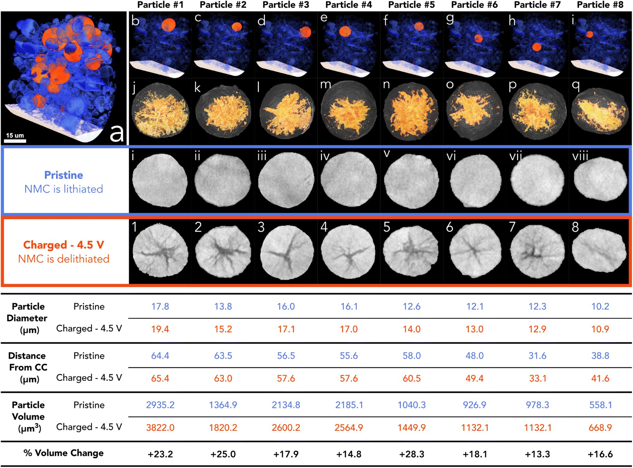 | ||
| Fig. 2 (a) Volume rendering of merged pristine electrode showing the current collector in white, analysed particles in orange, and other particles in blue. (b–i) Volume rendering of merged electrode showing the particle location of particles 1 to 8 in orange. (j–q) Surface rendering of charged particle with volume rendering of the segmented cracking within (yellow). (i–vii) Pristine particle centre ortho slice. (1–8) Charged particle centre ortho slice. Table below shows corresponding size and location values for each particle above. More particles than highlighted here have also been analysed (see Fig. S1†). | ||
Although the crack volume now contributes to the overall particle volume (particle volume post charging is defined as NMC + cracked voxels within the particle boundary (see Fig. S2†)), we may have expected a more modest increase, if we use the expansion of specific lattice parameters as a possible origin of particle expansion. Some increase in the volume can be attributed to the volume expansion of lattice grains in the c-lattice direction (up to 5%), and then during collapse the reduction in size manifests as intergranular cracking. However, this expansion is approximately 2% in this direction with the a-lattice parameter up to 210 mA h g−1.2 it is conceivable that during expansion of the c-lattice to 4.1 V, the crystal grains (which are orientated randomly) experience a variety of complex stress/strain interactions, maximised at the grain boundaries. We propose that the overall volume expansion of the secondary agglomerate is due to the release of thermally induced residual stresses when grain boundary cracking occurs. The residual stresses may have been introduced during the high-temperature sintering process while the primary particles were fused. When the stresses are released during the delithiation process, the particles will expand and impinge upon one another, resulting in a net volume expansion. Substantiating this hypothesis is a matter for future work.
As shown previously, there is a tendency for composite electrodes to exhibit gradients in material utilisation due to diffuse transport limitations arising from slow diffusion of lithium ions; coupled with high toruosities from the carbon binder network, the material closest to the separator is more active than the material at the current collector surface, meaning that there is a spatial polarisation within the electrodes.44,45 Often, more lithium is extracted from the separator region and thus can reach a higher local potential. The volumetric strain distribution was analysed through the thickness of the electrode and showed a slight tendency for particles at the separator to undergo a larger volume expansion; however, this was established from only 15 particles in the electrode with an R2 value of 0.49 hence is not a statistically significant result (see Fig. S2†). The size of the pristine particle may also play a role in the cracking behaviour as charging occurs; however, it was shown that the size of the particle had an insignificant effect on the volume expansion between pristine and 4.5 V, with no discernible trend (see Fig. S2†). Although, at higher C-rates than that employed here (C/50), both sources of SoC heterogeneities (electrode thickness and particle diameter) may become more prominent.25,44,46,47
In the first instance, analysis was conducted on the particle including all crack voxels, but in addition, we report the crack volume subsequently segmented as a separate phase to the NMC material (i.e. NMC + crack, analysed separately). On average, the crack volume was approximately 9% of the total volume, with the largest amount of cracking occupying 16% of the total particle volume (see Fig. 3k and l). Additionally, the crack volume did not account for all of the absolute volume increase of each particle; in the best cases about 70% of the volume increase was associated with “segmentable” crack volume via a greyscale thresholding method as described in the methods section. However, the residual volume increase was not able to be accounted for at this resolution and can be assumed to be associated with fractures smaller than the 124 nm voxel resolution. This phenomenon, known as partial averaging, occurs when voxels are occupied by two phases and thus NMC voxels that have a reduction in intensity due to the inclusion of void space.48 Due to the difference between the volume increase and the crack volume, it would appear that the NMC fraction of the particle had increased, but as discussed above we believe this to be due to unresolvable crack formation.
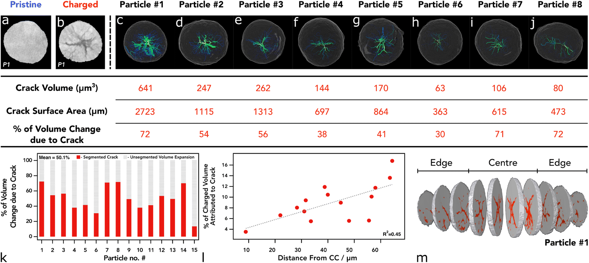 | ||
| Fig. 3 (a and b) Ortho slice of particle 1 at (a) pristine and (b) charged state. (c–j) Surface rending of 8 charged particles with skeletonised crack structure within, colour represents mean radius and line thickness represents volume. The table below shows the corresponding results from the crack segmentation. (k) Graph showing the % of particle volume change that is attributed to segmented crack. (l) Percentage of total particle volume occupied by the segmented crack. (m) Split rendering of particle 1 showing the crack (red) concentrated in the centre portions. | ||
We also see a higher proportion of cracking towards the centre of the particle that reduces in severity when tracing radially outwards towards the particle surface (see Fig. 3 and 4). This is a feature noted previously with electrochemically induced cracking, as opposed to cracks that have been induced by the manufacturing process which tend to have a more random orientation, however, this has yet to be proven beyond speculation of the initial condition of the particle.6,12 Again, the location of each particle was assessed in accordance with their cracking nature. Particles that reside closest to the separator show a higher percentage of “segmentable” cracking with respect to the total particle volume, thus suggesting that particles at the separator form larger, more broad, void structures and particles at the current collector develop smaller cracks that are more evenly distributed, rather than a single large void in the centre of the particle with micro-cracks forming off this structure (Fig. 3k). Whilst cracks of less than 124 nm are technically un-resolvable, its is well documented with higher resolution techniques that they exist in charged/aged NMC811 particles and thus can be reliably attributed to volume increase even if they are unable to be visualised.49,50 This phenomenon may be explained by a lithium diffusion rate factor, where particles that are able to delithiate quickly at the separator, go through intraparticle polarisation from the centre of the particle, and thus exhibit greater anisotropic mechanical stresses on the particles causing large void structures in the centre, as shown previously with operando measurements on single particles.47 Conversely, particles at the current collector exhibit a more modest lithium diffusion rate and therefore do not have such an elevated level of polarisation within the particle, causing cracking to occur more homogeneously throughout the particle and therefore less likely to be segmented as a separate phase at the resolution used in these CT investigations. We understand that at the rate used here this may lead to a more homogenous distribution of intraparticle delithiation states, however, similar observations have been reported by previous electrochemo-mechanical and phase field modelling that also showed higher damage in the centre of secondary particles at the separator region.25 Another possible explanation for this might be the presence of residual stresses as described previously, where the greatest residual stresses may reside in the centre of the particles and correspond with the large central voids, although this wouldn't explain the prevalence of this phenomenon at the separator, unless a significant c-rate polarisation existed through the electrode thickness which we wouldn't expect here.
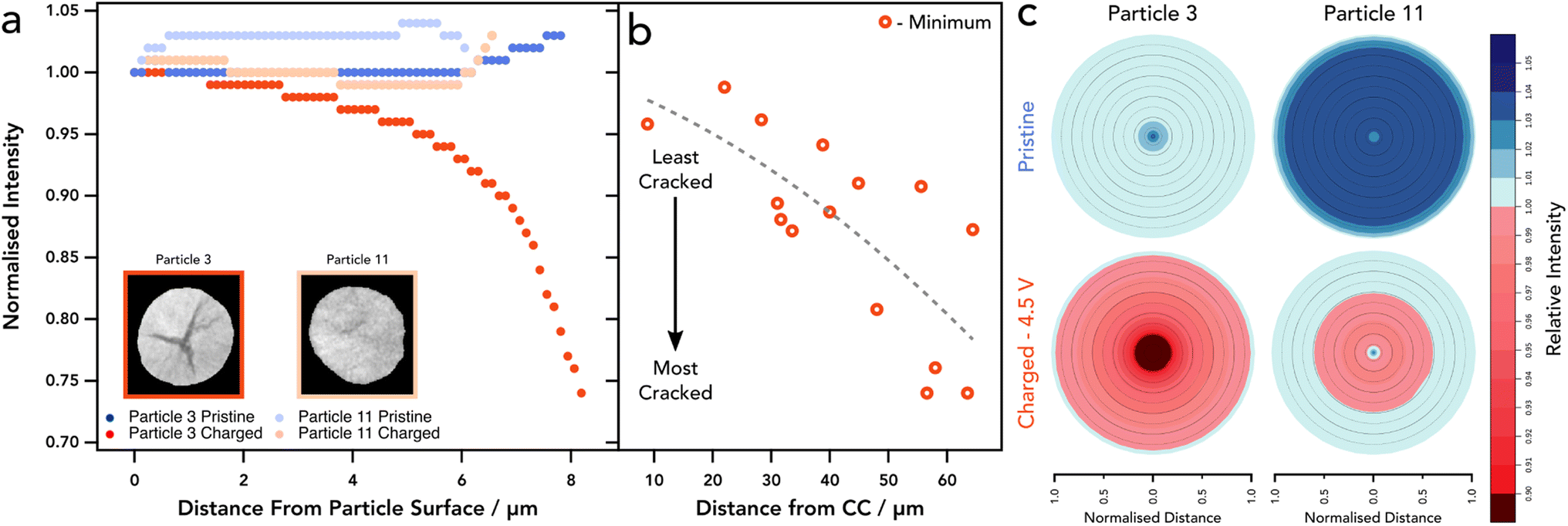 | ||
| Fig. 4 (a) GREAT analysis of exemplar particles with different cracking profiles, with ortho slice of each particle inset. (b) Through thickness analysis of minimum normalised intensity value for all particles. (c) Radial distribution plots of pixel intensity showing cracked areas in red and un-cracked areas in blue. | ||
3.2 Fracture modeling
In order to interpret the experimental results and gain insight into the fracture behaviour during the entire charging process, we now consider the chemomechanical fracture model. Fig. 5a illustrates the 3D geometry of a single particle of diameter ∼14 μm extracted from the X-ray CT image, while Fig. 5b shows the associated computational mesh, with a cutout showing a selection of the 400 randomly generated primary particles. The particle was charged at a rate of C/50 and it is clear from Fig. 5c that there is good agreement between the simulated voltage response and that of the experiment. We note that the discrepancy at low voltages is likely due to the fact that we are modelling a single particle and there are no effects of electrolyte or transport limitations through a full electrode, for example.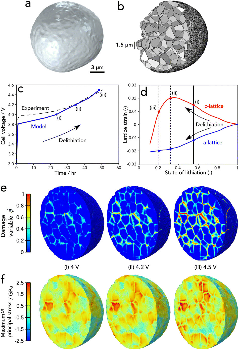 | ||
| Fig. 5 (a) Model geometry extracted from X-ray CT. (b) Cut-out of the underlying agglomerate microstructure comprising 400 primary particles. (c) Comparison of the single particle voltage with the experimental cell voltage response. (d) The lattice parameter strains as measured by Xu et al.21 (e) The phase field damage variable and (f) maximum principal stress profiles at a cut-out mid-way through the particle. | ||
In general, the damage response from the single particle model corresponds with that of the experiment – high levels of damage are found to occur at a charged state of 4.5 V. The present model indicates that this is a result of the anisotropic deformation of the primary particle lattice and their random orientation relative to their neighbouring crystal within the secondary particle agglomerate. The relationship between lattice strains and degree of lithiation, as measured by Xu et al.21 is shown in Fig. 5d; we highlight the points of crack initiation, and progression of fracture (i–iii), which correspond with the same markings on the voltage response in Fig. 5c and the damage and stress profiles of Fig. 5e. Note that the damage variable in Fig. 5e shows damage when ϕ = 1 and undamaged otherwise. The principal stress profiles of Fig. 5e highlight (a) the significant degree of heterogeneity in the stress response as a result of the randomly oriented primary particles, (b) their transversely isotropic behaviour when lithiated and (c) the high levels of tensile stresses that exist within the particles from c-axis stretching and the tensile stresses at the boundaries due to the tendency for particles to pull away from one another as they contract due to delithiation.
The particle damage process during charging proceeds as follows: the majority of cracks initiate within the central region of the particles at a c-lattice strain of 0.015. This happens at a voltage of approximately 4 V as shown in Fig. 5e(i). As delithiation proceeds, a small number of cracks continue to initiate and subsequently propagate outwards with increasing severity as the c-lattice strain increases to a maximum at approximately 0.55 state of lithiation; this can be observed in Fig. 5e(ii). Finally, once the peak in the c-lattice strain is reached, lattice collapse occurs and the bulk contraction of the particles follows, resulting in a steep increase in the level of damage as shown in Fig. 5e(iii). While the maximum principal stress relaxes in the regions of newly developed cracks, it is clear that this relaxation is not enough to inhibit further crack growth and stresses continuously ramp upwards during charging. We note that the majority of damage was located along the particle boundaries. We find little evidence of cracks branching into the grains; however, a deeper analysis of the mechanisms that govern this in 3D particles is left for future work. The interested reader can find such analysis of 2D idealised structures in the work of Singh et al.23
The trends observed by the model match that of the experiment; however, there are two phenomena that are not explained by the simulations here and have not been observed in the literature to the best of the authors' knowledge: the large voids that open in the centre of the particles, and the outward expansion of the particles by 13–25%. As stated previously, these phenomena are likely to be due to residual stresses from the manufacturing process, and it remains as future work to include thermally induced residual stresses within the model to account for this behaviour. It must also be noted that another failure mechanism is not considered here: delamination at the particle–carbon binder interface is possible and contributes to electrical isolation of the active material.21 It can be modelled using the present approach,23 however it is beyond the scope of this study and carbon binder domain is non-trivial to resolve properly using adsorption CT.
4 Conclusions
To fully understand cracking mechanisms exhibited in next generation Li-ion batteries we must be able to decouple mechanically induced cracking triggered during manufacturing from cracking introduced under electrochemical control. Here we have presented a methodology by which the structure and integrity of the electrode and the particles can be preserved within a commercially relevant setting, for sequential imaging and electrochemical operation. Employing a unique electrode design required for limited FoV X-ray CT, we have shown that it is possible to consecutively image the same RoI in both a pristine and charged state to directly monitor, extract, and quantify cracks directly induced by electrochemical activity. This provides the first of its kind analysis on a commercial electrode (active NMC material within a CBD matrix), in a set up where the internal structure of the particles is imaged non-destructively, with sufficient resolution to resolve the intergranular cracking.Image processing revealed that secondary particles tend to increase in volume during charging and will crack aggressively at a voltage above the c-lattice collapse. Cracking primarily exhibits within the centre of the particles and then reduces in severity radially, proving that electrochemical cracking has distinct directional properties. This method presents a pertinent procedure for future imaging of the same RoI that can be registered to an initial pristine state, allowing for understanding of how the propagation of cracking occurs over a matrix of voltages, rates, and health states. The lack of an obvious correlation between rate-limitations (particle size, electrode thickness) can be attributed to the very slow rate and relatively low electrode loading; we anticipate that at faster rates, a more apparent correlation would be observed, which is an avenue for future experimentation.
In addition, we have modelled the fracture behaviour using an X-ray CT based chemomechanical finite element model that shows a clear link between primary particle anisotropy and significant cracking at elevated voltages. We predict crack initiation in the centre of the particle at approximately 4 V that propagates outwards as voltage increases – this is commensurate with the experimental evidence. Excessive cracking at 4.5 V can be directly linked with the collapse of the c-lattice, at which point the primary particles undergo aggressive contraction that generates tensile stresses at the joints between their neighbours.
This technique could be applied to other chemistries including single crystal and solid state electrolytes as a an easy way to confirm the origin of cracking and the cracking tendencies in these materials. In addition, phase contrast imaging could be used in the future to resolve the carbon binder domain of the electrode and elucidate any contribution to secondary particle cracking that may be missed here. For all next generation chemistries looking to be employed in EVs, it is paramount to understand the cracking and loss of conductive contact behaviour to help mitigate these and prolong the lifetimes of cells, which may contribute to a reduction in battery wastage as they become more prominent in the automotive industry.
Data availability
Data can be found for open access usage at DOI: 10.5522/04/22120061 under CC by 4.0 licence.Author contributions
HP conducted all computed tomography imaging and image processing analysis. AB developed phase field model with EMP. AW conducted GREAT analysis on computed tomography data. TH and CT conceived of experimental design and analysis. PS, DB, and RJ supervised all experimentation. All authors contributed to manuscript and review process.Conflicts of interest
Authors declare no competing interests.Acknowledgements
This work was carried out with funding from the Faraday Institution (https://www.faraday.ac.uk; EP/S003053/1), grant numbers FIRG001, FIRG003, FIRG015, FIRG0024 and FIRG25; and the EPSRC grant EP/M014045/1. In addition, PhD funding for HP and AW by the Faraday Institution is also acknowledged: EPSRC training grant number EP/S514901/1. E. Martínez-Pañeda was supported by an UKRI Future Leaders Fellowship [grant MR/V024124/1].References
- N. Nitta, F. Wu, J. T. Lee and G. Yushin, Li-ion battery materials: present and future, Mater. Today, 2015, 18, 252–264 CrossRef CAS.
- K. Märker, P. J. Reeves, C. Xu, K. J. Griffith and C. P. Grey, Evolution of structure and lithium dynamics in LiNi0. 8Mn0. 1Co0. 1O2 (NMC811) cathodes during electrochemical cycling, Chem. Mater., 2019, 31, 2545–2554 CrossRef.
- C. Xu, K. Märker, J. Lee, A. Mahadevegowda, P. J. Reeves, S. J. Day, M. F. Groh, S. P. Emge, C. Ducati and B. L. Mehdi, et al., Bulk fatigue induced by surface reconstruction in layered Ni-rich cathodes for Li-ion batteries, Nat. Mater., 2021, 20, 84–92 CrossRef CAS PubMed.
- A. S. Leach, A. V. Llewellyn, C. Xu, C. Tan, T. M. Heenan, A. Dimitrijevic, K. Kleiner, C. P. Grey, D. J. Brett and C. C. Tang, et al., Spatially Resolved Operando Synchrotron-Based X-Ray Diffraction Measurements of Ni-Rich Cathodes for Li-Ion Batteries, Front. Chem. Eng., 2022, 3, 794194 CrossRef.
- J. Li, R. Shunmugasundaram, R. Doig and J. Dahn, In situ x-ray diffraction study of layered Li–Ni–Mn–Co oxides: effect of particle size and structural stability of core–shell materials, Chem. Mater., 2016, 28, 162–171 CrossRef CAS.
- H.-H. Ryu, K.-J. Park, C. S. Yoon and Y.-K. Sun, Capacity fading of Ni-rich Li [Ni x Co y Mn1–x–y] O2 (0.6 ≤ x ≤ 0.95) cathodes for high-energy-density lithium-ion batteries: bulk or surface degradation?, Chem. Mater., 2018, 30, 1155–1163 CrossRef CAS.
- T. Li, X.-Z. Yuan, L. Zhang, D. Song, K. Shi and C. Bock, Degradation mechanisms and mitigation strategies of nickel-rich NMC-based lithium-ion batteries, Electrochem. Energy Rev., 2020, 3, 43–80 CrossRef.
- R. Jung, M. Metzger, F. Maglia, C. Stinner and H. A. Gasteiger, Oxygen release and its effect on the cycling stability of LiNixMnyCozO2 (NMC) cathode materials for Li-ion batteries, J. Electrochem. Soc., 2017, 164, A1361 CrossRef CAS.
- L. de Biasi, B. Schwarz, T. Brezesinski, P. Hartmann, J. Janek and H. Ehrenberg, Chemical, structural, and electronic aspects of formation and degradation behavior on different length scales of Ni-Rich NCM and Li-Rich HE-NCM cathode materials in Li-Ion batteries, Adv. Mater., 2019, 31, 1900985 CrossRef.
- T. M. Heenan, A. Wade, C. Tan, J. E. Parker, D. Matras, A. S. Leach, J. B. Robinson, A. Llewellyn, A. Dimitrijevic and R. Jervis, et al., Identifying the Origins of Microstructural Defects Such as Cracking within Ni-Rich NMC811 Cathode Particles for Lithium-Ion Batteries, Adv. Energy Mater., 2020, 10, 2002655 CrossRef CAS.
- H. Wu, C. Qin, K. Wang, X. Han, M. Sui and P. Yan, Revealing two distinctive intergranular cracking mechanisms of Ni-rich layered cathode by cross-sectional scanning electron microscopy, J. Power Sources, 2021, 503, 230066 CrossRef CAS.
- X. Cheng, Y. Li, T. Cao, R. Wu, M. Wang, H. Liu, X. Liu, J. Lu and Y. Zhang, Real-time observation of chemomechanical breakdown in a layered nickel-rich oxide cathode realized by in situ scanning electron microscopy, ACS Energy Lett., 2021, 6, 1703–1710 CrossRef CAS.
- P.-C. Tsai, B. Wen, M. Wolfman, M.-J. Choe, M. S. Pan, L. Su, K. Thornton, J. Cabana and Y.-M. Chiang, Single-particle measurements of electrochemical kinetics in NMC and NCA cathodes for Li-ion batteries, Energy Environ. Sci., 2018, 11, 860–871 RSC.
- P. Liu, E. Sherman and A. Jacobsen, Design and fabrication of multifunctional structural batteries, J. Power Sources, 2009, 189, 646–650 CrossRef CAS.
- T. M. Heenan, C. Tan, J. Hack, D. J. Brett and P. R. Shearing, Developments in X-ray tomography characterization for electrochemical devices, Mater. Today, 2019, 69–85 CrossRef CAS.
- C. Tan, S. Daemi, T. Heenan, F. Iacoviello, A. Leach, L. Rasha, R. Jervis, D. Brett and P. Shearing, Rapid preparation of geometrically optimal battery electrode samples for nano scale X-ray characterisation, J. Electrochem. Soc., 2020, 167, 060512 CrossRef CAS.
- M. Klinsmann, D. Rosato, M. Kamlah and R. M. McMeeking, Modeling crack growth during Li insertion in storage particles using a fracture phase field approach, J. Mech. Phys. Solids, 2016, 92, 313–344 CrossRef CAS.
- W. Ai, B. Wu and E. Martínez-Pañeda, A coupled phase field formulation for modelling fatigue cracking in lithium-ion battery electrode particles, J. Power Sources, 2022, 544, 231805 CrossRef CAS.
- C. Miehe, H. Dal, L.-M. Schänzel and A. Raina, A phase-field model for chemo-mechanical induced fracture in lithium-ion battery electrode particles, Int. J. Num. Methods Eng., 2016, 106, 683–711 CrossRef.
- A. Mesgarnejad and A. Karma, Phase field modeling of chemomechanical fracture of intercalation electrodes: Role of charging rate and dimensionality, J. Mech. Phys. Solids, 2019, 132, 103696 CrossRef CAS.
- B.-X. Xu, Y. Zhao and P. Stein, Phase field modeling of electrochemically induced fracture in Li-ion battery with large deformation and phase segregation, GAMM-Mitteilungen, 2016, 39, 92–109 CrossRef.
- M. Ahmadi, A hybrid phase field model for fracture induced by lithium diffusion in electrode particles of Li-ion batteries, Comput. Mater. Sci., 2020, 184, 109879 CrossRef CAS.
- A. Singh and S. Pal, Chemo-mechanical modeling of inter-and intra-granular fracture in heterogeneous cathode with polycrystalline particles for lithium-ion battery, J. Mech. Phys. Solids, 2022, 163, 104839 CrossRef CAS.
- J. M. Allen, P. J. Weddle, A. Verma, A. Mallarapu, F. Usseglio-Viretta, D. P. Finegan, A. M. Colclasure, W. Mai, V. Schmidt and O. Furat, et al., Quantifying the influence of charge rate and cathode-particle architectures on degradation of Li-ion cells through 3D continuum-level damage models, J. Power Sources, 2021, 512, 230415 CrossRef CAS.
- A. M. Boyce, E. Martínez-Pañeda, A. Wade, Y. S. Zhang, J. J. Bailey, T. M. Heenan, D. J. Brett and P. R. Shearing, Cracking predictions of lithium-ion battery electrodes by X-ray computed tomography and modelling, J. Power Sources, 2022, 526, 231119 CrossRef CAS.
- E. Martínez-Pañeda, A. Golahmar and C. F. Niordson, A phase field formulation for hydrogen assisted cracking, Comput. Methods Appl. Mech. Eng., 2018, 342, 742–761 CrossRef.
- W. Li and K. Shirvan, Multiphysics phase-field modeling of quasi-static cracking in urania ceramic nuclear fuel, Ceram. Int., 2021, 47, 793–810 CrossRef CAS.
- M. Simoes and E. Martínez-Pañeda, Phase field modelling of fracture and fatigue in Shape Memory Alloys, Comput. Methods Appl. Mech. Eng., 2021, 373, 113504 CrossRef.
- C. Tan, A. S. Leach, T. M. M. Heenan, H. Parks, R. Jervis, J. N. Weker, D. J. L. Brett and P. R. Shearing, Nano-Scale State-of-Charge Heterogeneities within Polycrystalline Ni-Rich Layered Oxide Cathode Materials, Cell Rep. Phys. Sci., 2021, 2(12), 100647 CrossRef CAS.
- N. Otsu, A threshold selection method from gray-level histograms, IEEE Trans. Syst. Man Cybern. Syst., 1979, 9, 62–66 Search PubMed.
- F. Brosa Planella, W. Ai, A. M. Boyce, A. Ghosh, I. Korotkin, S. Sahu, V. Sulzer, R. Timms, T. G. Tranter and M. Zyskin, et al., A continuum of physics-based lithium-ion battery models reviewed, Prog. Energy, 2022, 4(4), 042003 CrossRef.
- A. A. V. I. Griffith, The phenomena of rupture and flow in solids, Philos. Trans. R. Soc. London, 1921, 221, 163–198 CrossRef.
- G. A. Francfort and J.-J. Marigo, Revisiting brittle fracture as an energy minimization problem, J. Mech. Phys. Solids, 1998, 46, 1319–1342 CrossRef.
- B. Bourdin, G. A. Francfort and J.-J. Marigo, The variational approach to fracture, J. Elasticity, 2008, 91, 5–148 CrossRef.
- E. Tanné, T. Li, B. Bourdin, J.-J. Marigo and C. Maurini, Crack nucleation in variational phase-field models of brittle fracture, J. Mech. Phys. Solids, 2018, 110, 80–99 CrossRef.
- J. C. Stallard, L. Wheatcroft, S. G. Booth, R. Boston, S. A. Corr, M. F. De Volder, B. J. Inkson and N. A. Fleck, Mechanical properties of cathode materials for lithium-ion batteries, Joule, 2022, 6, 984–1007 CrossRef CAS.
- T. M. Heenan, A. V. Llewellyn, A. S. Leach, M. D. Kok, C. Tan, R. Jervis, D. J. Brett and P. R. Shearing, Resolving Li-Ion Battery Electrode Particles Using Rapid Lab-Based X-Ray Nano-Computed Tomography for High-Throughput Quantification, Adv. Sci., 2020, 2000362 CrossRef CAS.
- Y. Yang, R. Xu, K. Zhang, S.-J. Lee, L. Mu, P. Liu, C. K. Waters, S. Spence, Z. Xu and C. Wei, et al., Quantification of Heterogeneous Degradation in Li-Ion Batteries, Adv. Energy Mater., 2019, 1900674 CrossRef.
- Y. Zhang, Z. Yang and C. Tian, Probing and quantifying cathode charge heterogeneity in Li ion batteries, J. Mater. Chem. A, 2019, 23628–23661 RSC.
- T. Heenan, D. Finegan, B. Tjaden, X. Lu, F. Iacoviello, J. Millichamp, D. J. Brett and P. Shearing, 4D nano-tomography of electrochemical energy devices using lab-based X-ray imaging, Nano Energy, 2018, 47, 556–565 CrossRef CAS.
- X. Lu, A. Bertei, D. P. Finegan, C. Tan, S. R. Daemi, J. S. Weaving, K. B. O'Regan, T. M. Heenan, G. Hinds and E. Kendrick, et al., 3D microstructure design of lithium-ion battery electrodes assisted by X-ray nano-computed tomography and modelling, Nat. Commun., 2020, 11, 2079 CrossRef CAS.
- A. Wade, A. V. Llewellyn, T. M. M. Heenan, C. Tan, D. J. L. Brett, R. Jervis and P. R. Shearing, First cycle cracking behaviour within Ni-rich cathodes during high-voltage charging, J. Electrochem. Soc., 2023, 170(7), 070513 CrossRef.
- A. Wade, T. Heenan, M. Kok, T. Tranter, A. Leach, C. Tan, R. Jervis, D. Brett and P. Shearing, A greyscale erosion algorithm for tomography (GREAT) to rapidly detect battery particle defects, npj Mater. Degrad., 2022, 6, 1–13 CrossRef.
- Z. Li, L. Yin, G. S. Mattei, M. R. Cosby, B.-S. Lee, Z. Wu, S.-M. Bak, K. W. Chapman, X.-Q. Yang and P. Liu, et al., Synchrotron Operando Depth Profiling Studies of State-of-Charge Gradients in Thick Li (Ni0. 8Mn0. 1Co0. 1) O2 Cathode Films, Chem. Mater., 2020, 32, 6358–6364 CrossRef CAS.
- H. Liu, Z. Li, A. Grenier, G. E. Kamm, L. Yin, G. S. Mattei, M. R. Cosby, P. G. Khalifah, P. J. Chupas and K. W. Chapman, Best practices for operando depth-resolving battery experiments, J. Appl. Crystallogr., 2020, 53, 133–139 CrossRef CAS.
- Z. Du, D. L. Wood, C. Daniel, S. Kalnaus and J. Li, Understanding limiting factors in thick electrode performance as applied to high energy density Li-ion batteries, J. Appl. Electrochem., 2017, 47, 405–415 CrossRef CAS.
- C. Xu, A. J. Merryweather, S. S. Pandurangi, Z. Lun, D. S. Hall, V. S. Deshpande, N. A. Fleck, C. Schnedermann, A. Rao and C. P. Grey, Operando visualization of kinetically induced lithium heterogeneities in single-particle layered Ni-rich cathodes, Joule, 2022, 6, 2535–2546 CrossRef CAS.
- T. Heenan, C. Tan, R. Jervis, X. Lu, D. Brett and P. Shearing, Representative resolution analysis for X-ray CT: a solid oxide fuel cell case study, Chem. Eng. Sci.: X, 2019, 4, 100043 CAS.
- G. Qian, Y. Zhang, L. Li, R. Zhang, J. Xu, Z. Cheng, S. Xie, H. Wang, Q. Rao and Y. He, et al., Single-crystal nickel-rich layered-oxide battery cathode materials: synthesis, electrochemistry, and intra-granular fracture, Energy Storage Mater., 2020, 27, 140–149 CrossRef.
- Q. Lin, W. Guan, J. Zhou, J. Meng, W. Huang, T. Chen, Q. Gao, X. Wei, Y. Zeng and J. Li, et al., Ni–Li anti-site defect induced intragranular cracking in Ni-rich layer-structured cathode, Nano Energy, 2020, 76, 105021 CrossRef CAS.
Footnote |
| † Electronic supplementary information (ESI) available. See DOI: https://doi.org/10.1039/d3ta03057a |
| This journal is © The Royal Society of Chemistry 2023 |