
 Open Access Article
 This Open Access Article is licensed under a
 Creative Commons Attribution 3.0 Unported Licence
Unravelling the CO2 capture and conversion mechanism of a NiRu–Na2O switchable dual-function material in various CO2 utilisation reactions†
Loukia-Pantzechroula
Merkouri
a,
Juan Luis
Martín-Espejo
b,
Luis F.
Bobadilla
b,
José Antonio
Odriozola
 b,
Anna
Penkova
b,
Tomas
Ramirez Reina
b and
Melis S.
Duyar
*a
b,
Anna
Penkova
b,
Tomas
Ramirez Reina
b and
Melis S.
Duyar
*a
aSchool of Chemistry and Chemical Engineering, University of Surrey, Guildford, GU2 7XH, UK. E-mail: m.duyar@surrey.ac.uk
bDepartment of Inorganic Chemistry and Materials Sciences Institute, University of Seville-CSIC, 41092, Seville, Spain
First published on 23rd May 2023
Abstract
Time-resolved operando DRIFTS-MS was performed to elucidate the CO2 capture and conversion mechanisms of a NiRuNa/CeAl DFM in CO2 methanation, reverse water–gas shift, and dry reforming of methane. CO2 was captured mainly in the form of carbonyls and bidentate carbonates, and a spillover mechanism occurred to obtain the desired products.
 Melis S. Duyar | Dr Melis Duyar is a Senior Lecturer in the School of Chemistry and Chemical Engineering at the University of Surrey. She has a research background in heterogeneous catalysis for energy and environmental applications. Her current research interests include the development of novel adsorbent materials for CO2 capture, catalytic/dual function materials for CO2 utilisation, and chemical upcycling of microplastics. Dr Duyar received her BSc (2012) in Chemical and Biological Engineering from Koç University. She obtained her M.S. (2013) and PhD (2015) in Earth and Environmental Engineering from Columbia University and conducted post-doctoral research (2015–2017) in the Chemical Engineering Department at Stanford University. Prior to her academic appointment at the University of Surrey (2019), she worked at the US Department of Energy's SLAC National Accelerator Laboratory as Associate Staff Scientist at the SUNCAT Center for Interface Science and Catalysis and was also Lecturer of Chemical Engineering at Stanford University (2017–2019). |
Introduction
Efforts to mitigate climate change have recently been intensified as we are approaching 2030, when a significant drop in greenhouse emissions needs to be achieved so as to meet the target of net-zero emissions by 2050.1–4 Capturing CO2, either from stationary sources or directly from the air, and storing it in underground formations, or utilising it to produce high-value chemicals and fuels, is considered essential so as to attain the net zero.5–7 Dual-function materials (DFMs) offer a modular solution to the circular economy since they integrate the CO2 capture and utilisation steps, eliminating the high costs of CO2 compression and transportation. Consisting of both a mid-temperature adsorbent and a catalyst, DFMs are able to reversibly capture CO2 at intermediate temperatures and then convert it into the desired products.8–10The most studied reaction with DFMs is the CO2 methanation reaction (eqn (1)) and DFMs have been optimised so that CO2 capture and methanation can be performed at the same temperature, ca. 300–350 °C. In addition, the main product is CH4, or synthetic natural gas, which can be introduced to the current natural gas grid.11 However, DFMs have been studied in other reactions as well, such as reverse water-gas shift, dry reforming of methane, and dry reforming of ethane, all of which produce syngas with various H2/CO ratios (eqn (2)–(4)).12–20 Therefore, it is evident that DFMs can be applicable to a wide range of CO2 utilisation technologies. Moreover, if the same DFM is able to operate in more than one CO2 utilisation reaction by simply changing the reaction conditions, it is possible to devise switchable systems that can respond to fluctuations in reactant supply or product demand.15 By using switchable DFMs, flexible chemical synthesis can be accomplished, thus overcoming the market uncertainties which result from fluctuations in the supply and demand.
| CO2 methanation: CO2 + 4H2 → CH4 + 2H2O | (1) |
| RWGS: CO2 + H2 → CO + H2O | (2) |
| DRM: CO2 + CH4 → 2CO + 2H2 | (3) |
| DER: 2CO2 + C2H6 → 4CO + 3H2 | (4) |
The urgency of achieving net-zero emissions makes it a priority to understand the DFMs at a fundamental level. By perceiving the various reaction intermediates that are formed and the reaction pathway that each species promotes, connections between structure and activity can be made, leading to a faster DFM optimisation. Diffuse Reflectance Infrared Fourier Transform Spectroscopy (DRIFTS) is a key technique for elucidating the reaction mechanism that is used to observe the evolution of adsorbed, desorbed, and intermediate species over a catalyst surface under working conditions. We have previously shown that NiRuNa/CeAl acts as a switchable DFM that first captures the CO2 and subsequently catalyses methanation, RWGS, and DRM by adjusting the temperature and co-reactant (H2 or CH4) used.15 We have also demonstrated that CO2 adsorption on different adsorbent sites also has an effect on selectivity, indicating that the mechanism of reaction on DFMs is closely connected to the interaction of CO2 with the DFM surface during the capture step, in addition to its interaction with the catalytic sites during the subsequent reduction step. As a result, DRIFTS data can help with the reaction mechanism comprehension in order to synthesise more efficient DFMs in the future, allowing to tune up the selectivity and reactivity of DFMs. Even though some mechanistic studies have been performed for CO2 capture and utilisation separately,21–26 there are only few DRIFTS studies of DFMs to date,12,19,27–30 creating the need for further investigation of the structure–activity relations.
In this project, a DFM consisting of Ni and Ru as the active catalytic species and Na as the adsorbent, prepared and analysed in our previous work,15 was used to elucidate the mechanism during CO2 capture and conversion. In particular, 5 cycles of CO2 capture and conversion were performed, with the targeted reactions being CO2 methanation, RWGS, and DRM.
Results and discussion
Ex situ characterisation: XPS and particle size analysis
Fig. 1a is a representative TEM image of the NiRuNa sample and Fig. 1b shows its particle size distribution. The average particle size was calculated to be 6.3 nm. Overall, small nanoparticles were observed, showing that a good dispersion of the active species was achieved during the DFM synthesis. XPS results are demonstrated in Fig. 1c and d, displaying the Ru 3p and Na 1s regions. It can be seen that Ru had a mixture of reduced (Ru0) and oxidised species (Ru4+), with the oxidised species being predominant. This is attributed to the air exposure prior to the measurement of DFM and to the fact that XPS is a surface technique. Previously conducted XRD of the reduced NiRuNa sample showed no Ru0 peaks despite the fact that the fresh sample displayed RuO2 peaks, demonstrating the high dispersion of Ru species and/or the Ni–Ru alloy formation,15 further proving that a thin oxidised layer was formed after air exposure. In Fig. 1d, the Na 1s region presents a single peak at 1071.6 eV ascribed to carbonate species,31 in accordance with the DRIFTS spectra after reduction (not shown here) and its CO2-TPD profile showing CO2 release at room temperature.15 The Ni and Ce XPS regions can be found in the ESI in Fig. S1.†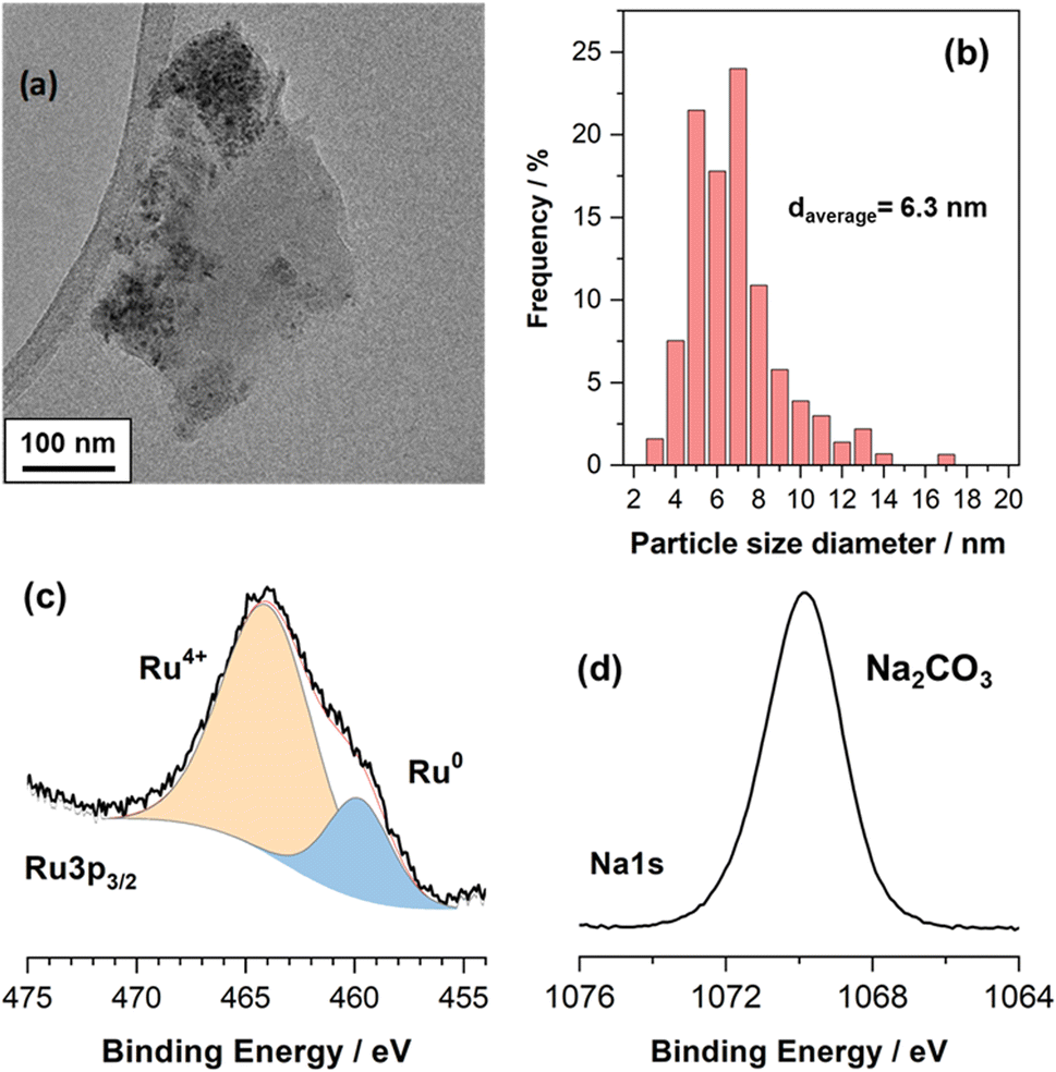 | ||
| Fig. 1 Ex situ characterisation of NiRuNa sample (a) representative TEM image. (b) Particle size distribution based on TEM images. (c) Ru 3p XPS region. (d) Na 1s XPS region. | ||
Time-resolved operando DRIFTS-MS experimental analysis
In order to get insights into the surface intermediates involved and obtain relevant mechanistic aspects during CO2 capture and subsequent reduction reaction, we performed an operando DRIFTS-MS study by alternating successive CO2 capture and H2 or CH4 cycles under isothermal conditions at 250 °C for methanation and 550 °C for RWGS and DRM reactions. MS-data can be found in the ESI in Fig. S2, S3, and S4.†CO2 capture and methanation
Fig. 2a contains a bidimensional representation of the dynamic evolution of the spectra successively recorded during the alternated cycles of CO2 capture and methanation at 250 °C. All IR spectra were subtracted with respect to the spectrum of the surface activation for distinguishing between emerging and disappearing species. As can be noticed, the development of bands ascribed to gaseous CO2 (2360 cm−1) and the symmetric/asymmetric stretching OCO vibrations typical of carbonate species (1600–1300 cm−1) were clearly distinguished during the CO2 capture period. It is also worth observing the appearance of bands ascribed to CO adsorbed on metal sites (1900–2000 cm−1) during the capture step, revealing that CO2 may be dissociatively adsorbed as CO* and O* species. The presence of ruthenium decreased the energy barrier for CO2 dissociation and promoted the subsequent hydrogenation of CO* adsorbed species.32 Likewise, CO2 could also be reduced to CO onto the oxygen-deficient sites of the CeO2–Al2O3 support, and CO migrated to form carbonyl species adsorbed on metal sites.33 This was coherent with the absence of gaseous CO. After switching from the CO2 capture to H2 reduction stream, the evolution of a new band at 3016 cm−1 attributed to gaseous methane was observed, which was the predominant product.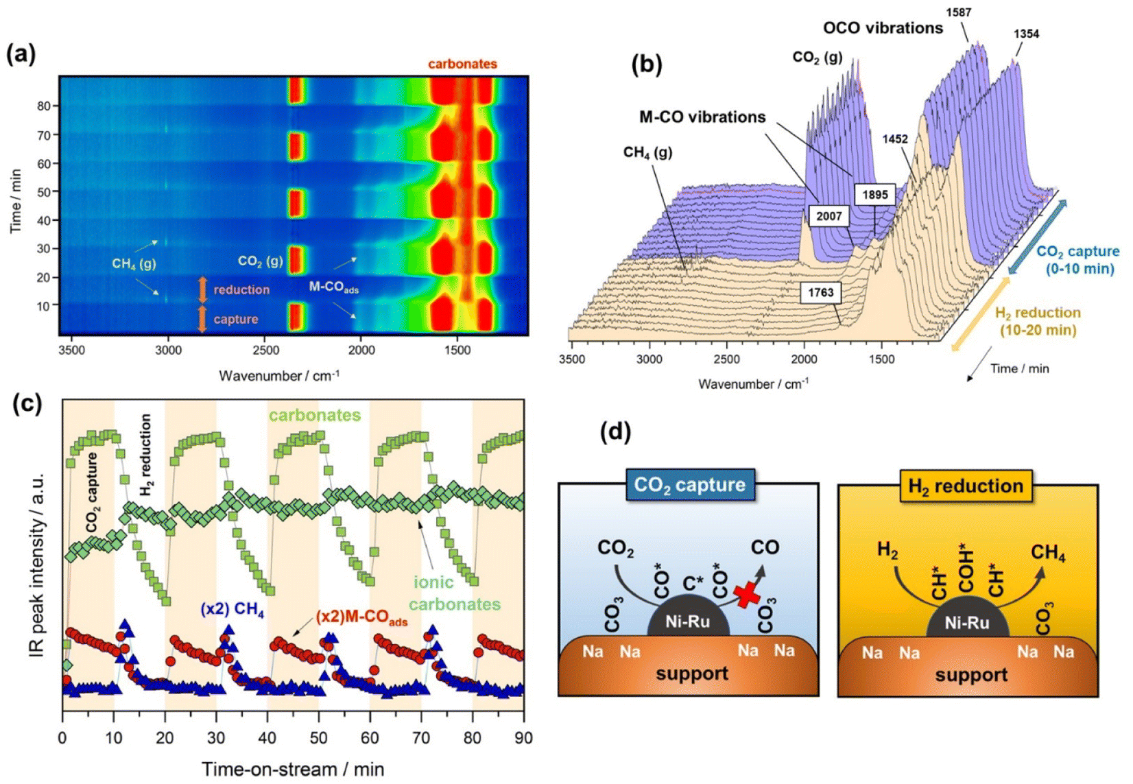 | ||
| Fig. 2 (a) Bidimensional representation of time-resolved DRIFTS spectra on the reduced NiRuNa/CeAl during capture/reduction cycles (10% CO2 in Ar and 10% H2 in Ar, both at 50 mL min−1) at 250 °C. (b) Representative evolution of spectra during the first cycle of capture/reduction. (c) Evolution of selected IR bands signal during the capture/reduction cycles: CH4 (3016 cm−1), ionic carbonates (1452 cm−1), carbonates (1587 cm−1) and M–COads (2007 cm−1) (d) illustrative sketch of the capture/reduction process on NiRuNa/CeAl. | ||
In more detail, Fig. 2b shows the evolution of the IR spectra collected during the first cycle of capture/reduction. As can be seen, the spectra recorded during the CO2 capture stage (0–10 min) were dominated by the presence of two intense bands in the 1800–1200 cm−1 region. These bands were ascribed to the symmetric and asymmetric stretching vibrations related to carbonate-like species with different adsorption geometry on the basic sites of the support. Accordingly, the pair of bands at 1587–1354 cm−1 (Δν3 splitting = 233) were associated with bridged or bidentate carbonates.28,34,35 It has been suggested that CO2 is preferably adsorbed, forming bidentate carbonates on Al–O–Na sites over Na-promoted catalysts.28 It is noteworthy that the intensity of these bands only decreased slightly after switching to the 10% H2/Ar stream, indicating that bidentate carbonates were only partially removed at 250 °C. In addition, other two features at 1452 and 1763 cm−1 were clearly visible and remained stable during the reduction step. These two bands are typical of very symmetric D3h alkali carbonates with high ionicity degree.36,37 As can be observed, these species were highly stable and remained on the surface upon switching to the reduction stream. Moreover, it should be noted that bicarbonate species could be formed by reaction between CO2 and surface hydroxyls. However, the bands related to bicarbonate species (1225, 1430, and 1650 cm−1) were absent due to the fact that sodium addition neutralised the hydroxyl groups on the support surface.38
As regards the bands developed in the CO stretching region (2100–1800 cm−1), two bands at 2007 and 1895 cm−1 emerged during the capture step. These two features were respectively ascribed to linear and bridged carbonyl-adsorbed species on metallic sites. In our recent work,39 we suggested that an induced electron transfer from Ru to Ni atoms, resulting in metallic sites with high electron density existed, redshifting the carbonyl stretching vibrations. The presence of carbonyl-adsorbed species during CO2 capture step revealed that CO2 was partially dissociated into CO* and O* on metallic sites, or reduced on the oxygen vacancies of the cerium-promoted sites of the support. Besides, the fact that CO was further dissociated into C* and O* species could not be ruled out in this case because it is known that this path is facilitated by Ru sites.40 It should be noted that vibrational modes of carbon species are hardly detectable by IR.
Fig. 2c displays the evolution of the IR bands intensities ascribed to bidentate carbonates (1587 cm−1), ionic carbonates (1452 cm−1), linearly CO* bounded species (2007 cm−1), and CH4 gas formation (3016 cm−1) as a function of time during the successive capture and reduction cycles. It is interesting to note that upon switching to the H2 stream, bidentate carbonates were partially depleted with a simultaneous increase in the concentration M–CO adsorbed species and production of methane. Likewise, it was clearly evidenced that ionic carbonates were accumulated on the surface. These species were thermally stable and required higher temperatures to be decomposed and/or reduced. Based on these observations, we could conclude that bidentate carbonates were reduced to CO* adsorbed species and subsequently hydrogenated into methane in a sequential reaction pathway (eqn (5)).
 | (5) |
Loveless et al.41 report that the step of CO hydrogenation on ruthenium sites involves the formation of formyl species (CHO*) that are subsequently hydrogenated into methane or larger hydrocarbons. In another theoretical study, in which density functional theory (DFT) calculations were applied, it was calculated that the direct dissociation of CO2 to CO* and O* is favoured on Ru (0001) terraces, and that the subsequent CO hydrogenation occurs via either COH* or CHO* intermediates formation.32 Although formyl species were scarcely detected in our study, we could not overlook their presence in the form of very kinetically labile intermediates. Accordingly, Fig. 2d includes a schematic representation of the steps involved in the CO2 capture and H2 reduction steps.
CO2 capture and reverse water–gas shift
In the following case study, analogous successive cycles of CO2 capture and H2 reduction were performed at 500 °C to enable the RWGS against the methanation reaction. As can be observed in Fig. 3a and b, the bands involved in the process at 500 °C were similar to those observed at 250 °C. However, it was remarkable that upon switching to H2 atmosphere, most of the captured CO2 like bidentate (1587–1354 cm−1) and ionic carbonate (1452 cm−1) species reacted with H2 over the NiRu active sites, releasing the reduction product composed predominantly by gaseous CO accompanied by some traces of CH4. The IR intensity profiles shown in Fig. 3c clearly evidence that the reduction kinetic of carbonates was much faster at 500 °C, and the surface was regenerated to initiate a new cycle of capture after reduction. As can be noticed, the formation of carbonates during CO2 capture step was accompanied by dissociation of CO2, which was more facile at 500 °C, achieving high initial coverage of CO* adsorbed species (linear at 2007 cm−1 and bridged at 1895 cm−1), which were in turn progressively desorbed, releasing CO gas. As sketched in Fig. 3d, we propose two parallel routes for CO formation during integrated CO2 capture and RWGS. The first route is an associative reaction mechanism in which carbonates species are formed during CO2 capture phase and subsequently reduced to CO gas during the reduction stage. At the same time, a dissociative mechanism also occurs on the metal sites during CO2 capture step in which CO* adsorbed species (linear and bridged) are formed and subsequently desorbed, liberating CO gas (Fig. S3†). Accordingly, Fig. 3c and S3† show that CO gas was released in two routes, evident from the two peaks ascribed to the adsorbed CO* species on the metal sites and the CO gas from the reduction of carbonates. The presence of some traces of methane could be explained, considering that the temperature was not sufficiently high from the thermodynamic viewpoint so as to completely favour the RWGS reaction against methanation, and minor quantities of CO* adsorbed species and/or carbonates were sequentially reduced to methane.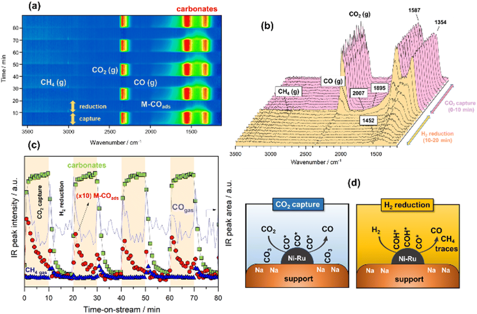 | ||
| Fig. 3 (a) Bidimensional representation of time-resolved DRIFTS spectra on the reduced NiRuNa/CeAl during capture/reduction cycles (10% CO2 in Ar and 10% H2 in Ar, both at 50 mL min−1) at 500 °C. (b) Representative evolution of spectra during the first cycle of capture/reduction. (c) Evolution of selected IR bands signal during the capture/reduction cycles: CO gas (area of left-peak at 2143 cm−1), carbonates (1587 cm−1) and M–COads (2007 cm−1) (d) illustrative sketch of the capture/reduction process on NRuNa/CeAl. | ||
Some authors have proposed that the reduction of CO2 either to methane or CO takes place via the formation of formates following an associative mechanism. For instance, Proaño et al.27 suggest that methanation occurs through sequential hydrogenation with formates as reaction intermediaries. It is well known that bicarbonates are firstly formed by the reaction of CO2 with hydroxyls, and they are subsequently reduced to formates at the metal/support interfacial sites. The formates are the main intermediates for producing CO or CH4 depending on the reaction conditions.26 In our study, we observed that the reaction followed a different reaction pathway since the hydroxyls were neutralised with sodium, and the formation of bicarbonates was inhibited. Consequently, formates could not be produced. Herein, the initial step involved the reduction of carbonates to CO* adsorbed species and the subsequent formation of HCO* intermediates by hydrogenation of CO* adsorbed species onto the metal sites. In the case of methanation, the following step comprised the reaction between HCO* and H* to form HCOH* species, which dissociated into CH* and OH* with the subsequent hydrogenation into methane.41 In the case of RWGS, the hydrogenation of CO* was inhibited by the temperature, and CO was directly released. A similar mechanism was proposed by Hu and Urakawa,19 who found that alkali promoted catalysts lead to the formation of formyls and bidentate carbonates as main intermediates for the methanation reaction, but with the formyl species being the most active surface species for the CH4 production.
CO2 capture and dry reforming of methane
Finally, in the last approach unsteady-state, dry reforming reaction was performed by alternatingly passing 10% CO2/Ar and 10% CH4/Ar gas streams under isothermal conditions at 500 °C. It should be stressed that this approach made use of the coke generated by methane dissociation to reduce the CO2 captured, following a process known as chemical looping CH4 conversion coupled with CO2 utilisation.42 In our case study, the cycles started by the CH4 reduction atmosphere and successive cycles of reduction/capture were performed. As shown in Fig. 4a, several weak features emerged in the 1700–1300 and 3300–3100 cm−1 regions when the flow of 10% CH4/Ar was introduced. The intensity of these bands became gradually more intense when the CH4 exposure was advancing during the cycles. More specifically, two bands at 1340 and 1663 cm−1 (Fig. 4b) together with another broad one centred at 3245 cm−1 (shown in Fig. 4a) were ascribed to vibrational modes characteristic of graphitic carbon,43 which was produced from the CH4 decomposition favoured at this low reforming temperature by thermodynamics.44 More specifically, the bands at 1663 and 1340 cm−1 were respectively ascribed to conjugated C![[double bond, length as m-dash]](https://www.rsc.org/images/entities/char_e001.gif) C stretching vibrations and cyclic carbon groups, whereas the band at 3245 cm−1 may have been related to “in-plane” overtones of highly ordered or crystalline graphite.45–48 This reaction was confirmed by the simultaneous production of H2, detected by MS (Fig. S4†). On the other hand, it was observed from Fig. 4b that bands, typical of bidentate carbonates (1587–1354 cm−1), were formed during the CO2 capture phase with simultaneous production of CO gas. In addition, the presence of CO* adsorbed species with linear (2007 cm−1) and bridged (1895 cm−1) coordination on metal sites was detected, while it was also possible that Ru could have further promoted CO* dissociation into C* and O*, as mentioned earlier. It should be remarked that in this case, the CO production was not only attributed to the CO2 dissociation on metal active sites, but also to the gasification of the
C stretching vibrations and cyclic carbon groups, whereas the band at 3245 cm−1 may have been related to “in-plane” overtones of highly ordered or crystalline graphite.45–48 This reaction was confirmed by the simultaneous production of H2, detected by MS (Fig. S4†). On the other hand, it was observed from Fig. 4b that bands, typical of bidentate carbonates (1587–1354 cm−1), were formed during the CO2 capture phase with simultaneous production of CO gas. In addition, the presence of CO* adsorbed species with linear (2007 cm−1) and bridged (1895 cm−1) coordination on metal sites was detected, while it was also possible that Ru could have further promoted CO* dissociation into C* and O*, as mentioned earlier. It should be remarked that in this case, the CO production was not only attributed to the CO2 dissociation on metal active sites, but also to the gasification of the  species, following the reverse Boudouard reaction shown below (eqn (6)).
CO2 + C* ![[left over right harpoons]](https://www.rsc.org/images/entities/char_21cb.gif) CO CO | (6) |
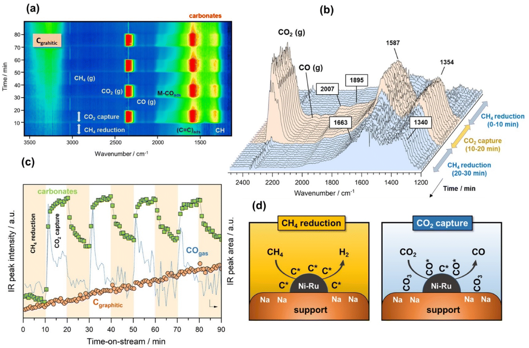 | ||
| Fig. 4 (a) Bidimensional representation of time-resolved DRIFTS spectra on the reduced NiRuNa/CeAl during reduction/capture cycles (10% CH4 in Ar and 10% CO2 in Ar, both at 50 mL min−1) at 500 °C. (b) Representative evolution of spectra during the first cycle of reduction/capture/reduction. (c) Evolution of selected IR bands signal during the capture/reduction cycles: CO gas (area of left-peak at 2143 cm−1), carbonates (1587 cm−1) and CHads (3245 cm−1) (d) illustrative sketch of the capture/reduction process on NiRuNa/CeAl. | ||
This fact was reflected in Fig. 4c, where the first cycle of CO2 capture clearly showed two differentiated peaks of CO production, both related to CO2 dissociation and CO2 gasification. It should be noted that the first peak of the CO progressively dropped, whereas the second one dropped more drastically. At the same time, the intensity of the band at 3245 cm−1 ascribed to highly ordered graphitic carbon increased with the time of reaction regardless of the gas used, i.e. CO2 or CH4. This implied slower kinetics of the coke gasification by CO2 during the capture step than the kinetics of the overall coke formation and consequently, a rapid deactivation of the catalyst in which the nickel metal sites became blocked and the support's pores were recovered with carbonaceous deposits. Fig. 4d includes a representative illustration of the phenomena occurring in both the CH4 reduction and CO2 capture steps. Coke is hardly avoided under these conditions due to the thermodynamic restrictions as mentioned earlier, and its accumulation on the catalyst surface causes deactivation. However, this culprit can be overcome using temperatures above 700 °C, in which the endothermic Boudouard reaction is thermodynamically and kinetically more favoured.
It is worth mentioning that these DRIFTS findings were in contrast to our previous work, demonstrating that when the DFM was exposed to CO2 and then CH4, the captured CO2 was converted into CO.15 Consequently, the order of gases, CH4 and CO2, affected the performance of the material. DRIFTS indicated that CO2 was adsorbed onto the adsorbent sites (carbonates signal), but only part of this signal disappeared upon re-exposure to CH4. In contrast to our previous findings,15 upon exposure to CH4, the adsorbed CO2 was partially released as CO2 (gas peak shown in Fig. 4a), and the rest remained adsorbed as carbonates, meaning that none was converted into CO during the DRM step, as the MS data in Fig. S4† and the CO gas signal in Fig. 4c confirmed. When comparing the DRIFTS data for DRM and RWGS, it was observed that in the RWGS experiments almost all the carbonate peaks disappeared upon exposure to H2. An explanation for that might be that not all the CO2 was captured reversibly and that some of the carbonates formed at a Na–Ni/Ru interface. If that interface was coke free, it would have allowed further conversion into CO. By performing CH4 cracking first, these metal/adsorbent interfaces were blocked, preventing the captured CO2 from reacting. This mechanism highlights the need to control methane cracking during DRM operation of the DFM, through process engineering and material design.
Conclusions
Time-resolved operando DRIFTS was performed to understand the mechanism of CO2 capture and then, CO2 methanation, RWGS, or DRM on a NiRuNa/CeAl DFM. This was the first mechanistic study on a switchable DFM, providing us with insight into three important CO2 utilisation reaction pathways that were previously unknown. In this work, it was revealed that during the capture step, CO2 was dissociated on the metallic sites and reduced on the oxygen-deficient sites of Ce, and that bridged and bidentate carbonates were also formed. During the DRM capture step, CO was also produced due to the coke gasification with the available CO2, while CH4 decomposition took place during the DRM step, producing H2. As far as the conversion steps are concerned, the formation of HCO* intermediates by hydrogenation of CO* adsorbed species onto the metal sites was observed when H2 was used as a co-reactant. However, CO was liberated in the case of RWGS, while it was subsequently hydrogenated into CH4 in the case of CO2 methanation. Overall, it was evident that these findings elucidated the reaction mechanism of DFMs, paving the way of optimised materials formulations in the near future, with maximised catalyst–adsorbent interface, tuned adsorption strength, and site distribution so as to achieve full conversion and higher selectivity.Author contributions
Loukia-Pantzechroula Merkouri: conceptualisation, methodology, validation, formal analysis, investigation, writing – original draft, visualisation. Juan Luis Martín-Espejo: methodology, validation, formal analysis, investigation, visualisation. Luis Francisco Bobadilla: methodology, formal analysis, resources, writing – original draft, writing – review & editing, visualisation, supervision. José Antonio Odriozola: formal analysis, resources, funding acquisition. Anna Penkova: formal analysis, investigation. Tomás Ramirez Reina: conceptualisation, methodology, resources, writing – review & editing, supervision, project administration, funding acquisition. Melis S. Duyar: conceptualisation, methodology, resources, writing – review & editing, supervision, project administration, funding acquisition.Conflicts of interest
There are no conflicts to declare.Acknowledgements
This research was funded by the School of Chemistry and Chemical Engineering and the Doctoral College of the University of Surrey. This work was partially sponsored by the European Commission through the H2020-MSCA-RISE-2020 BIOALL project (Grant Agreement: 101008058). L. P. Merkouri acknowledges the Erasmus+ programme, which allowed her to conduct part of the experiments in Seville, Spain. L.-P. Merkouri also thanks Dr Vlad Stolojan of the Department of Electrical and Electronic Engineering for his assistance with TEM training. The team at University of Seville also acknowledge financial support from the Spanish Ministry of Science through the projects NICER-BIOFUELS (ref: PLEC2021-008086), sponsored by MCIN/AEI/10.13039/501100011033 Next Generation Europe SMART-FTS (ref: PID2021-126876OB-I00).Notes and references
- United Nations Framework Convention on Climate Change, Adoption of the Paris Agreement, Paris, 2015 Search PubMed.
- J. Rogelj, M. Den Elzen, N. Höhne, T. Fransen, H. Fekete, H. Winkler, R. Schaeffer, F. Sha, K. Riahi and M. Meinshausen, Nature, 2016, 534, 631–639 CrossRef CAS PubMed.
- United Nations, Climate change: No ‘credible pathway’ to 1.5C limit, UNEP warns, accessed 3 March 2023, https://news.un.org/en/story/2022/10/1129912 Search PubMed.
- IEA, An updated roadmap to Net Zero Emissions by 2050, accessed 9 December 2022, https://www.iea.org/reports/world-energy-outlook-2022/an-updated-roadmap-to-net-zero-emissions-by-2050 Search PubMed.
- IEA, CCUS in the transition to net-zero emissions, accessed 3 March 2023, https://www.iea.org/reports/ccus-in-clean-energy-transitions/ccus-in-the-transition-to-net-zero-emissions Search PubMed.
- J. C. M. Pires, F. G. Martins, M. C. M. Alvim-Ferraz and M. Simões, Chem. Eng. Res. Des., 2011, 89, 1446–1460 CrossRef CAS.
- A. Al-Mamoori, A. Krishnamurthy, A. A. Rownaghi and F. Rezaei, Energy Technol., 2017, 5, 834–849 CrossRef.
- L. P. Merkouri, T. R. Reina and M. S. Duyar, Energy Fuels, 2021, 35, 19859–19880 CrossRef CAS.
- I. S. Omodolor, H. O. Otor, J. A. Andonegui, B. J. Allen and A. C. Alba-Rubio, Ind. Eng. Chem. Res., 2020, 59, 17612–17631 CrossRef CAS.
- S. Sun, H. Sun, P. T. Williams and C. Wu, Sustainable Energy Fuels, 2021, 5, 4546–4559 RSC.
- M. S. Duyar, M. A. A. Treviño and R. J. Farrauto, Appl. Catal., B, 2015, 168–169, 370–376 CrossRef CAS.
- H. Sun, J. Wang, J. Zhao, B. Shen, J. Shi, J. Huang and C. Wu, Appl. Catal., B, 2019, 244, 63–75 CrossRef CAS.
- H. Sun, Y. Wang, S. Xu, A. I. Osman, G. Stenning, J. Han, S. Sun, D. Rooney, P. T. Williams, F. Wang and C. Wu, Fuel, 2021, 286, 119308 CrossRef CAS.
- A. Al-Mamoori, A. A. Rownaghi and F. Rezaei, ACS Sustainable Chem. Eng., 2018, 6, 13551–13561 CrossRef CAS.
- L.-P. Merkouri, R. Reina and M. S. Duyar, Nanoscale, 2022, 14, 12620–12637 RSC.
- S. Bin Jo, J. H. Woo, J. H. Lee, T. Y. Kim, H. I. Kang, S. C. Lee and J. C. Kim, Sustainable Energy Fuels, 2020, 4, 5543–5549 RSC.
- S. Jo, J. H. Lee, J. H. Woo, T.-Y. Kim, H.-J. Ryu, B. Hwang, J. C. Kim, S. C. Lee and K. L. Gilliard-AbdulAziz, Sustainable Energy Fuels, 2022, 6, 81–88 RSC.
- L. F. Bobadilla, J. M. Riesco-García, G. Penelás-Pérez and A. Urakawa, J. CO2 Util., 2016, 14, 106–111 CrossRef CAS.
- L. Hu and A. Urakawa, J. CO2 Util., 2018, 25, 323–329 CrossRef CAS.
- S. Sun, Z. Lv, Y. Qiao, C. Qin, S. Xu and C. Wu, Carbon Capture Sci. Technol., 2021, 1, 100001 CrossRef CAS.
- J. Graciani, K. Mudiyanselage, F. Xu, A. E. Baber, J. Evans, S. D. Senanayake, D. J. Stacchiola, P. Liu, J. Hrbek, J. F. Sanz and J. A. Rodriguez, Science, 2014, 345, 546–550 CrossRef CAS PubMed.
- S. C. Qi, J. K. Wu, J. Lu, G. X. Yu, R. R. Zhu, Y. Liu, X. Q. Liu and L. B. Sun, J. Mater. Chem. A, 2019, 7, 17842–17853 RSC.
- S. C. Qi, X. Y. Liu, R. R. Zhu, D. M. Xue, X. Q. Liu and L. B. Sun, Chem. Eng. J., 2022, 430, 132784 CrossRef CAS.
- C. Vogt, J. Kranenborg, M. Monai and B. M. Weckhuysen, ACS Catal., 2020, 10, 1428–1438 CrossRef CAS.
- M. T. Dunstan, F. Donat, A. H. Bork, C. P. Grey and C. R. Müller, Chem. Rev., 2021, 121, 12681–12745 CrossRef CAS PubMed.
- X. Wang, Y. Hong, H. Shi and J. Szanyi, J. Catal., 2016, 343, 185–195 CrossRef CAS.
- L. Proaño, E. Tello, M. A. Arellano-Trevino, S. Wang, R. J. Farrauto and M. Cobo, Appl. Surf. Sci., 2019, 479, 25–30 CrossRef.
- L. Proaño, M. A. Arellano-Treviño, R. J. Farrauto, M. Figueredo, C. Jeong-Potter and M. Cobo, Appl. Surf. Sci., 2020, 533, 147469 CrossRef.
- D. Pinto, V. Van der Bom Estadella and A. Urakawa, Catal. Sci. Technol., 2022, 12, 5349–5359 RSC.
- Z. Zhou, N. Sun, B. Wang, Z. Han, S. Cao, D. Hu, T. Zhu, Q. Shen and W. Wei, ChemSusChem, 2020, 13, 360–368 CrossRef CAS PubMed.
- J. F. Moulder, W. F. Stickle, P. E. Sobol and K. D. Bomben, Handbook of X-Ray Photoelectron Spectroscopy, 1979, vol. 3 Search PubMed.
- S. T. Zhang, H. Yan, M. Wei, D. G. Evans and X. Duan, RSC Adv., 2014, 4, 30241–30249 RSC.
- M. Zhu, P. Tian, X. Cao, J. Chen, T. Pu, B. Shi, J. Xu, J. Moon, Z. Wu and Y. F. Han, Appl. Catal., B, 2021, 282, 119561 CrossRef CAS.
- L. Azancot, L. F. Bobadilla, M. A. Centeno and J. A. Odriozola, Appl. Catal., B, 2021, 285, 119822 CrossRef CAS.
- G. Busca and V. Lorenzelli, Mater. Chem., 1982, 7, 89–126 CrossRef CAS.
- S. Joshi, S. Kalyanasundaram and V. Balasubramanian, Appl. Spectrosc., 2013, 67, 841–845 CrossRef CAS PubMed.
- J. Kiefer, A. Strk, A. L. Kiefer and H. Glade, Energies, 2018, 11, 798 CrossRef.
- S. Navarro-Jaén, A. Szego, L. F. Bobadilla, Ó. H. Laguna, F. Romero-Sarria, M. A. Centeno and J. A. Odriozola, ChemCatChem, 2019, 11, 2063–2068 CrossRef.
- L. Merkouri, J. L. Martín-espejo, L. F. Bobadilla, J. A. Odriozola, M. S. Duyar and T. R. Reina, Nanomaterials, 2023, 13, 506 CrossRef CAS PubMed.
- J. Wang, Y. Wang and K. Jacobi, Surf. Sci., 2001, 488, 83–89 CrossRef CAS.
- B. T. Loveless, C. Buda, M. Neurock and E. Iglesia, J. Am. Chem. Soc., 2013, 135, 6107–6121 CrossRef CAS PubMed.
- Z. Zhou, Z. Sun and L. Duan, Curr. Opin. Green Sustainable Chem., 2023, 39, 100721 CrossRef CAS.
- V. Ţucureanu, A. Matei and A. M. Avram, Crit. Rev. Anal. Chem., 2016, 46, 502–520 CrossRef PubMed.
- T. Stroud, T. J. Smith, E. Le Saché, J. L. Santos, M. A. Centeno, H. Arellano-Garcia, J. A. Odriozola and T. R. Reina, Appl. Catal., B, 2018, 224, 125–135 CrossRef CAS.
- L. Bokobza, J. L. Bruneel and M. Couzi, Vib. Spectrosc., 2014, 74, 57–63 CrossRef CAS.
- B. Manoj, A. M. Raj and G. C. Thomas, Sci. Rep., 2018, 8, 13891 CrossRef PubMed.
- R. J. Nemanich and S. A. Solin, Phys. Rev., 1979, 20, 392–401 CAS.
- Y. Wang, D. C. Alsmeyer and R. L. McCreery, Chem. Mater., 1990, 2, 557–563 CrossRef CAS.
Footnote |
| † Electronic supplementary information (ESI) available. See DOI: https://doi.org/10.1039/d3ta01892j |
| This journal is © The Royal Society of Chemistry 2023 |