An ultrathin 2D NiCo-LDH nanosheet decorated NH2-UiO-66 MOF-nanocomposite with exceptional chemical stability for electrocatalytic water splitting†
Saddam
Sk
 ab,
Ragunath
Madhu
 bc,
Deepak S.
Gavali
d,
Vidha
Bhasin
e,
Ranjit
Thapa
d,
Shambhu Nath
Jha
e,
Dibyendu
Bhattacharyya
e,
Subrata
Kundu
 *bc and
Ujjwal
Pal
 *ab
*ab
aDepartment of Energy & Environmental Engineering, CSIR-Indian Institute of Chemical Technology, Hyderabad-500007, India. E-mail: upal03@gmail.com; ujjwalpal@iict.res.in
bAcademy of Scientific and Innovative Research (AcSIR), Ghaziabad-201002, India
cElectrochemical Process Engineering (EPE) Division, CSIR-Central Electrochemical Research Institute (CECRI), Karaikudi-630003, Tamil Nadu, India. E-mail: kundu.subrata@gmail.com; skundu@cecri.res.in
dDepartment of Physics, SRM University-AP, Amaravati 522240, Andhra Pradesh, India
eAtomic and Molecular Physics Division, Bhabha Atomic Research Centre, Mumbai 400085, India
First published on 14th April 2023
Abstract
Utilization of bifunctional high-efficiency non-precious electrocatalysts for stable and effective water splitting is crucial to the growth of the clean energy industry. Topologically, the predetermined ordered structures of metal–organic frameworks (MOFs) can be contrived through the judicious assembly of a tailor-made synthesis strategy of layered double hydroxide (LDH) films. Aiming at NiCo-LDH@NH2-UiO-66 as a model system, for the first time, we examine the 2-methyl imidazole-induced ultrathin 2D NiCo-LDH nanosheet arrays in NH2-UiO-66 as an effective bifunctional electrocatalytic system for overall H2O splitting with marvellous performance and robustness in alkaline environments. The progressively tuned NiCo-LDH@NH2-UiO-66 catalyst demands overpotential values of 296 and 224 mV to deliver a current density of 50 mA cm−2 for the O2 evolution reaction (OER) and H2 evolution reaction (HER) in 1 M KOH aqueous solution, respectively. Tafel studies also revealed favorable reaction kinetics during electrochemical processes. The NiCo-LDH@NH2-UiO-66 bifunctional electrode displayed superior activity exhibiting a voltage of 1.65 V at a benchmarking current density of 10 mA cm−2 towards overall water splitting. Importantly, the NiCo-LDH@NH2-UiO-66 electrode shows an excellent specific capacitance of 0.00364 mF cm−2 with remarkable durability of the capacitor after 1000 cycles. To compare with the experimental result, we have performed density functional theory (DFT)-based calculation to estimate the HER and OER activity of the NiCo-LDH@NH2-UiO-66 heterostructure. From the HER free energy profile and Bader charge analysis, we have confirmed that the presence of NH2-UiO-66 helps in H2 production with 0.10 eV free energy of H2 adsorption (GH*). From the OER free energy profile, the estimated overpotential (η) is about 0.96 eV, which confirms that the electrochemical reaction towards the OER is also possible on the NiCo-LDH@NH2-UiO-66 structure. This study will bestow a beneficial blueprint for the utilization of an effective, durable, and economical MOF-based bifunctional catalytic system for overall water splitting.
Introduction
Due to the concerns from the growing world population, rapid industrial development, the impending depletion of fossil fuels, global warming, and an energy crisis on a global scale, researchers are looking for an environmentally friendly yet economically viable alternative to sustainable green energy. In this regard, the conversion of solar/electric energy into chemical energy via photoelectric/electrically power-driven H2O splitting to obtain H2 fuel is one of the most promising and realistic ways.1–3 To achieve these objectives, there is an urgent requirement for effective electrocatalysts to improve the reaction kinetics since electrocatalytic water splitting is an energy-intensive process.4 As of now, Pt is acknowledged as the best HER electrocatalyst in acidic solutions, whereas noble metal-based materials like Ru, Ir, RuO2, and IrO2 are regarded as the benchmark OER electrocatalysts in alkaline as well as acidic aqueous solutions.5 However, owing to their restricted availability and prohibitive price, their commercial usage is severely constrained. So far various transition metal-based catalysts have been investigated for this technique.3,6,7 However, further work is needed to develop and synthesize novel robust and efficient inorganic electrocatalysts with excellent stability. In this context, MOFs, as a class of highly crystalline materials with a dynamic, adjustable porous structure and an abundance of active sites, are currently assumed to be suitable for OER and HER electrocatalytic performance.8,9 On the other hand, promoting both the OER and HER using identical electrodes is still a challenge that needs to be addressed.In this respect, a rational design and synthesis of NH2-UiO-66 catalysts, made up of Zr–O clusters and NH2-BDC organic linkers, has now been extensively researched for use in electrocatalytic overall H2O splitting with good stability.8 A potential structural motif on NH2-UiO-66 results in a larger electroactive surface area and more active sites, which may enhance the area of contact between the catalyst and the electrolyte as well as shorten the active species' diffusion pathways, both of which improve catalytic activity.10 With logical adjustment and development, this state-of-the-art demonstrates their potential to function as optimistic candidates for both the OER and HER. While adding dopants to a MOF could result in a better interface for the adsorption and active species activation, designing heterostructures might make it easier for active sites to be exposed, improving the electrocatalytic activity.11,12
In recent years, bimetallic LDHs, as one of the representatives of two-dimensional (2D) materials, are electrocatalysts for both the OER and HER because of their adaptable layered structure and chemical adaptability, which enhance their catalytically active sites, improve anion exchange capability, and enrich the charge/mass dynamics. As a well-known bimetallic LDH molecule, Ni and Co-based LDH have been intensively researched for highly effective and stable OER and HER electrocatalytic performance in alkaline environments.13,14 Subsequently, heterostructure electrocatalysts based on NiCo-LDH including NiCo-LDH/NiCo2S4,15 Co3O4@NiCo-LDH,16 Co9S8@NiCo-LDH,17 Co3S4@NiCo-LDH,18 MoS2/NiCo2S4,19 NiCo-LDH@NiCoP,20 Ni3S2/Cu–NiCo LDH,21 Ce3+ doped NiCo-LDH,22 V doped NiCo-LDH,23 and so on have been reported for overall H2O splitting. Based on the reports, the development and exploitation of bifunctional electrocatalytic systems for satisfactory HER and OER activities is the fundamental challenge, which alongside simplifying the experimental procedure and lowering the cost, also enhances the overall H2O splitting efficiency. For the optimization of the electronic structure and enhancement in the HER and OER activities, it is important to efficiently construct the desirable microscopic morphology and structure through elemental doping and heterostructure growth. As far as our literature survey is concerned, no research has been carried out to determine how the spatial location of the electron acceptor, ultrathin 2D nanosheet, and electronic properties influence the catalytic performance of 2-methylimidazole derived ultrathin NiCo-LDH nanosheet arrays. The complexing agent in this reaction was 2-methylimidazole, which was later substituted by a –OH functional group in the reaction system to successfully fabricate the ultrathin NiCo-LDH nanosheet.24 Moreover, the ultrathin nanosheet structure is favourable for the electrostatic self-assembly of the heterostructure with efficient charge separation for H2O splitting.25,26 To improve the charge transport and surface reaction kinetics, it is important to examine the structure–activity relationships of the 2D NiCo-LDH with NH2-UiO-66 for rational heterostructure development and synergistic impact of materials.
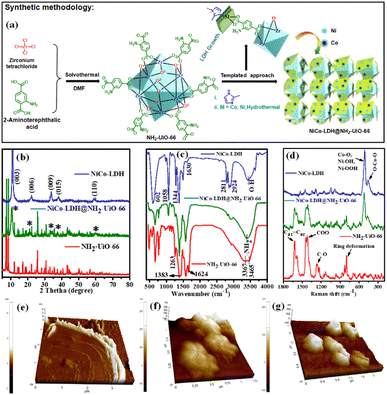
Herein, in this contribution, we demonstrate the novel report of making a new class of 2-methyl imidazole derived ultrathin 2D NiCo-LDH nanosheet arrays anchored via in situ growth on the NH2-UiO-66 octahedron surface (as shown in Fig. 1a; synthetic methodology) for efficient electrocatalytic OER, HER, and overall H2O splitting at room temperature via a facile and cost-effective strategy. Benefiting from its interfacial structure, the NiCo-LDH@NH2-UiO-66 catalyst demonstrated an excellent H2O splitting activity, obtaining a current density of 10 mA cm−2 at 1.65 V in an alkaline electrolyser, accompanied by outstanding durability. Furthermore, we have also used spectroscopic methods to thoroughly study the functions of each element in the binary system.
Results and discussion
Structure characterization of NiCo-LDH@NH2-UiO-66
Ultrathin NiCo-LDH nanosheets were synthesized using controlled hydrolysis of Ni and Co precursors in the presence of imidazole. For clarification, we named them NiCo-LDH (Ni![[thin space (1/6-em)]](https://www.rsc.org/images/entities/char_2009.gif) :
:![[thin space (1/6-em)]](https://www.rsc.org/images/entities/char_2009.gif) Co = 1
Co = 1![[thin space (1/6-em)]](https://www.rsc.org/images/entities/char_2009.gif) :
:![[thin space (1/6-em)]](https://www.rsc.org/images/entities/char_2009.gif) 1.07), as revealed by inductively coupled plasma-optical emission spectra (ICS-OES). The growth of NiCo-LDH nanosheets probably follows a similar mechanism to the co-axial-oriented growth of hydrotalcite-like Ni(OH)2 nanostructures.27 We have confirmed the formation of NiCo-LDH and NH2-UiO-66 nanocrystals by recording their powder XRD pattern (Fig. 1b). The NiCo-LDH@NH2-UiO-66 heterostructure was prepared using in situ growth of LDH in the presence of the MOF nanocrystals as schematically illustrated in Fig. 1a and S1.† The growth of the LDH has not been poised by the MOF and both the structures were retained without forming any phase impurities. The diffraction peaks of NiCo-LDH at 11.3°, 22.2°, 33.9°, 38.6°, and 59.6° correspond to the (003), (006), (009), (015), and (110) facets, respectively (JCPDS no. 38-0715).28,29 (Fig. 1b) On the other hand, all the series of diffraction peaks related to pristine NH2-UiO-66 match with the previous report.30
1.07), as revealed by inductively coupled plasma-optical emission spectra (ICS-OES). The growth of NiCo-LDH nanosheets probably follows a similar mechanism to the co-axial-oriented growth of hydrotalcite-like Ni(OH)2 nanostructures.27 We have confirmed the formation of NiCo-LDH and NH2-UiO-66 nanocrystals by recording their powder XRD pattern (Fig. 1b). The NiCo-LDH@NH2-UiO-66 heterostructure was prepared using in situ growth of LDH in the presence of the MOF nanocrystals as schematically illustrated in Fig. 1a and S1.† The growth of the LDH has not been poised by the MOF and both the structures were retained without forming any phase impurities. The diffraction peaks of NiCo-LDH at 11.3°, 22.2°, 33.9°, 38.6°, and 59.6° correspond to the (003), (006), (009), (015), and (110) facets, respectively (JCPDS no. 38-0715).28,29 (Fig. 1b) On the other hand, all the series of diffraction peaks related to pristine NH2-UiO-66 match with the previous report.30
Further, the FTIR spectra of pristine NH2-UiO-66, NiCo-LDH, and the in situ grown NiCo-LDH@NH2-UiO-66 heterostructure with peak assignments are presented in Fig. 1c. The spectra of NH2-UiO-66 are strikingly like those previously published and may be separated into three regions. The first region is below 1400 cm−1, and it comprises numerous bands corresponding to 2-amino terephthalate vibrations, like the noted peaks at 1263 and 1383 cm−1 attributed to the aromatic C and N bonding of the amine.31 The carboxylate interactions are associated with the second region from 1400 to 1600 cm−1. The range 1430–1533 cm−1 was measured more specifically, suggesting the existence of amino carboxylate molecules coordinating with the Zr metal core by the –COO asymmetrical stretching with peaks at 1499 and 1570 cm−1 and the –COO symmetrical stretching with peaks at 1584 and 1434 cm−1.32,33 Due to the obvious symmetric and asymmetric interactions of –NH2 on the organic linker, the region shows peaks at 3465 and 3367 cm−1.34 After the in situ growth of LDH on the MOF surface, the characteristic bands related to both NiCo-LDH and NH2-UiO-66 are observed in the FT-IR spectrum of the NiCo-LDH@NH2-UiO-66 heterostructure. The O–H stretching mode is confirmed by a wide band at roughly 3442 cm−1 as represented by a signature of molecular vibrations of intercalated anions of NiCo-LDH. The H2O molecule and –OH groups at the interlayer are thought to be responsible for balancing the positively charged Ni and Co in the framework layer.24 Furthermore, the bending mode of the H2O molecule's vibration spectrum is shown, with a peak at roughly 1630 cm−1, proving the presence of molecular H2O in the NiCo-LDH structure.35 Asymmetric stretching of interlayer CO32− anions is responsible for the strong peak at 1344 cm−1.36 The peaks at 1058, 2924, and 2811 cm−1 are attributed to the νC–O and νC–H modes of vibration of the interlayer MeOH molecules, while the peaks at roughly 602 cm−1 are ascribed to the vibrational modes of M–O or O–M–O/M–O–M (M = Ni and Co).37,38 Additionally, the structural properties of the samples are further investigated by Raman spectroscopy in Fig. 1d. For the NiCo-LDH nanosheet, the intense band at 508 cm−1 corresponds to the symmetric stretching vibrations of Co–O, Ni–OOH, and Ni–OH, whereas the band at 452 cm−1 corresponded to O–Co–O.39 The NH2-UiO-66 Raman signature is presented in the Raman spectrum of NiCo-LDH@NH2-UiO-66. The Raman spectra of NiCo-LDH@NH2-UiO-66 also showed a hypochromic shift, suggesting the existence of electronic interactions between NH2-UiO-66 and NiCo-LDH nanosheets. The weaker Raman peaks of the NiCo-LDH@NH2-UiO-66 can be attributed to the evolution of the crystalline structure,29 which is in line with the XRD results. The FT-IR and Raman results reflect the formation of the NiCo-LDH@NH2-UiO-66 nanostructure with retained structural integrity. Moreover, the thickness of the NiCo-LDH nanosheet was investigated by atomic force microscopy (AFM) to verify the ultrathin characteristics (Fig. 1e–g and S2†). The thickness of the NiCo-LDH nanosheet is around 1.5–3.5 nm (Fig. 1e and S2a†). The AFM images confirmed the successful synthesis of the ultrathin NiCo-LDH nanosheet. The outside and interior of the NiCo-LDH are nearly transparent due to its ultrathin thickness, which could contribute to the increase of specific surface areas to provide more active sites. The height profile for both NH2-UiO-66 and NiCo-LDH@NH2-UiO-66 is approximately 120–180 nm, which is in good agreement with the crystal size (Fig. 1f, g and S2b, c†).
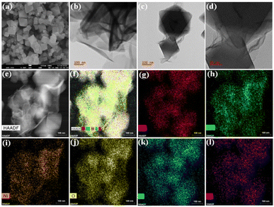
As our major focus lies on the morphological properties, NH2-UiO-66 displayed a large octahedral-like morphology with a smooth surface and sharp crystal edges (Fig. 2a and S3a†). On the other hand, the pristine NiCo-LDH showed microscale growth with hierarchical 2D nanosheet-like porous morphology (Fig. 2b, S3b, c & S4c†). The NiCo-LDH exhibited a stacked fishing network. However, the LDH growth was limited in the presence of MOF, and layers of LDH are seen to be irregularly wrapped but closely interfacing with the MOF crystals in the NiCo-LDH@NH2-UiO-66 heterostructure (Fig. 2c, d & S4f†). Interestingly, the achieved NiCo-LDH maintains the overall vertically aligned and interconnected nanosheet morphology in the presence of MOF. It demonstrated that the ultrathin nanosheets are anchored on the surface of the MOF template, which favours the exposure of active sites, leading to high catalytic performance. The (015) facet of the NiCo-LDH is visible in the high-resolution TEM profile and correlated with an interplanar spacing of 0.24 nm (Fig. S5†).24,29 Another point worth stating is that the NiCo-LDH@NH2-UiO-66 heterostructure reveals a strong contrast between its LDH nanosheets on the MOF surface from the high-angle annular dark-field scanning transmission electron micrograph (HAADF STEM) (Fig. 2e and f). The images show that all the elements are homogeneously distributed. Furthermore, the line profile of the NiCo-LDH@NH2-UiO-66 heterostructure (Fig. S7†) at a particular area reveals the presence of elements and verifies the high density of Ni, Co, and Zr metals. Alongside, energy dispersive X-ray (EDX) and elemental mapping analysis showed that the Ni, Co, and Zr metals were distributed throughout the whole NiCo-LDH@NH2-UiO-66 heterostructure composite (Fig. 2g–l and S8†).
Furthermore, the BET surface area and associated profiles of the pore size patterns for the materials are explored using nitrogen adsorption–desorption isotherm measurements at 77 K. The curves for the NH2-UiO-66, NiCo-LDH, and NiCo-LDH@NH2-UiO-66 materials are type IV isotherms with a typical H3 hysteresis circuit, as depicted in Fig. S9,† indicating that the materials are all mesoporous structures. The SBET of NH2-UiO-66, NiCo-LDH, and NiCo-LDH@NH2-UiO-66 was 668.7, 25.5, and 276.6 m2 g−1, respectively. (Table S1†) The higher specific surface area of the modulated NiCo-LDH@NH2-UiO-66 compared to NiCo-LDH is due to the formation of heterostructures which eventually alter the electronic and chemical properties of NiCo-LDH@NH2-UiO-66, leading to the formation of more active sites. Porous NH2-UiO-66, NiCo-LDH, and NiCo-LDH@NH2-UiO-66 have comparable pore size distribution curves. Meanwhile, NiCo-LDH@NH2-UiO-66 has a higher pore volume (0.37 cm3 g−1) and lower pore size (5.35 nm) than the NiCo-LDH, implying that the introduced LDH is grown on the surface of NH2-UiO-66 (Fig. S9 and Table S1†). NiCo-LDH@NH2-UiO-66 may create a new interface between the LDH and MOF that can facilitate charge transfer and provide more surface-active sites for improving the catalytic process. To investigate the weight loss of the MOF/LDH nanostructure, we used thermogravimetric quantitative analysis (TGA). Two distinct stages of weight loss were noticed in the NiCo-LDH, as depicted in Fig. S10.† The initial minor weight loss (∼5%) up to 250 °C occurs mainly because of the loss of surface and intercalated H2O molecules. In the next step, the major weight loss (∼35%) between 250 and 350 °C is due to interlayer anions and de-hydroxylation of LDH.40,41 On the other hand, the TGA profile of NH2-UiO-66 shows a small weight loss below 150 °C due to solvent volatilization. Next, the weight loss between 150 and 450 °C can be attributed to the elimination of monocarboxylate ligands and dihydroxylation of the Zr6 system.42,43 The magnitude of weight loss in the last step corresponds to the combustion of the linker/framework. NiCo-LDH@NH2-UiO-66 possessed thermal performances like NH2-UiO-66. The residue percentage of the NiCo-LDH@NH2-UiO-66 was much higher than that of NiCo-LDH, indicating that the in situ growth of LDH with the MOF system significantly improved the thermal stability.
The analysis by several methods to determine the formation of NiCo-LDH and the in situ growth of LDH on the MOF surface NiCo-LDH@NH2-UiO-66 heterostructure was followed by the application of X-ray photoelectron spectroscopy (XPS) measurements to learn more about the electronic states of the surface elements as well as the composition. As depicted in Fig. S11a,† NiCo-LDH@NH2-UiO-66 was primarily composed of all elements namely Zr, Co, Ni, N, C, and O contained in NiCo-LDH and NH2-UiO-66. In addition, as illustrated in Fig. S11b,† the Zr 3d spectrum is divided into four peaks. The peaks at 181.5 and 184.3 eV were ascribed to Zr–O bonds, and the peaks at 182.6 and 185.2 eV were ascribed to Zr–Zr bonds, therefore, illustrating the existence of Zr4+.44,45 The Zr 3d spectra of NiCo-LDH@NH2-UiO-66 are like the characteristic peaks of pristine NH2-UiO-66. In addition, NiCo-LDH@NH2-UiO-66's Co 2p spectra consist of two spin–orbit doublets and two shakeup satellites (Fig. S11c†). In particular, the peaks at 781.8 and 797.3 eV are ascribed to 2p3/2 and 2p1/2 of Co2+, respectively, while the peaks at 780.2 and 796.3 eV are ascribed to 2p3/2 and 2p1/2 of Co3+.24,39 The two shakeup satellite peaks are situated at 790.2 and 803.4 eV. As illustrated in Fig. S11d,† the characteristic peaks at 855.3 and 872.7 eV correspond to the 2p3/2 and 2p1/2 of Ni2+, respectively,46,47 and the peaks at 861.8 and 878.5 eV correspond to the satellite peaks. The Co 2p and Ni 2p spectra of NiCo-LDH@NH2-UiO-66 are like the characteristic peaks of pristine NiCo-LDH. Further, it can be seen clearly that the two N 1s peaks at 400.2 and 401.5 eV corresponding to –NH2 and –NH groups of the organic linkers in pristine NH2-UiO-66 are shifted to 399.7 and 401.1 eV, respectively, after the in situ growth of LDH, as shown in Fig. S11e.†48 In addition, deconvolution of the C 1s spectrum (Fig. S11f†) displays three characteristic peaks, which are located at 284.2, 285.3, and 288.2 eV assigned to C–H/C–C, C–N, and C–O respectively.38,49 As revealed in Fig. S11g,† HR-XPS spectra of O 1s have deconvoluted into two characteristics peaks at 530.8, and 531.9 eV related to the Zr–O bond and metal–hydroxyl bonding (Ni–OH and Co–OH), respectively.24,46,50 The result is believed to indicate the successful in situ growth of LDH on the MOF surface.
X-ray absorption spectroscopy (XAS) measurement
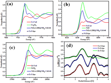
Fig. 3a–c shows the XANES spectra of the NiCo-LDH@NH2-UiO-66 sample at Co, Ni, and Zr K edges respectively along with that of Co foil, Co3O4, Ni foil, NiO, Zr foil, and ZrO2 as standards. Fig. 3a clearly depicts an enhancement in the effective charge of Co cations in the NiCo-LDH@NH2-UiO-66 sample as compared to that in Co3O4 as the absorption edge of the sample is shifted towards higher energy relative to that of standard Co3O4. Fig. 3b illustrates the XANES spectra of the NiCo-LDH@NH2-UiO-66 sample at the Ni K edge together with Ni metal foil and NiO as standards. A similar shift in the absorption edge of the sample towards higher energy is observed as compared to that of standard NiO, suggesting an increase in the effective charge of Ni cations in the NiCo-LDH@NH2-UiO-66 sample. Fig. 3c presents the XANES spectra of the NiCo-LDH@NH2-UiO-66 sample at the Zr K edge along with Zr metal foil and ZrO2 as standards. The shift in the absorption edge of the sample towards lower energy compared to that of standard ZrO2 could be due to the presence of Zr4+ in the NiCo-LDH@NH2-UiO-66 sample. The XANES spectra also confirm the partial reduction of the Zr4+ oxo-cluster and the existence of Zr4+ ions. Further, Fig. 3d presents the χ(r) versus r plots of the NiCo-LDH@UiO-66-NH2 sample at Co, Ni, and Zr K edges. The χ(r) versus r plot of the NiCo-LDH@NH2-UiO-66 sample at the Co K edge has been fitted from 1 to 3.1 Å assuming one Co–O shell and a Co–Ni/Co shell, and the χ(r) versus r plot at Ni K edge has been fitted from 1.1–3.2Å assuming one Ni–O shell and a Ni–Ni/Co shell and the χ(r) versus r plot at the Zr K edge has been fitted in the range of 1.25–2.2 Å assuming two Zr–O shells. The best-fit theoretical simulations have been shown in Fig. 3d along with the experimental data and the best-fit results are shown in Table S2.†Electrocatalytic performance of the OER in 1 M KOH electrolyte
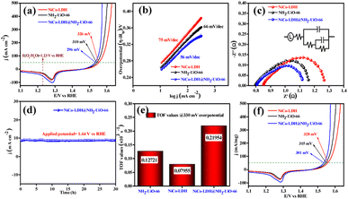
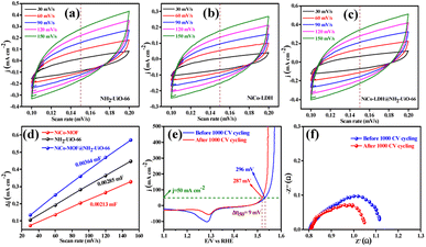
The electrocatalytic OER activities of NH2-UiO-66, NiCo-LDH, and NiCo-LDH@NH2-UiO-66 catalysts were analyzed in a standard three-electrode setup. The linear sweep voltammetry (LSV) curves of all the catalytic systems were analyzed at the fixed scan rate of 5 mV s−1 in an ‘Fe free’ 1 M KOH solution. For determining the accurate overpotential, backward LSV (60% iR compensation) from the positive to the negative potential of cyclic voltammetry (CV) was performed to eliminate the strong oxidation peak around a potential of 1.32–1.45 V (vs. RHE) and the obtained results are depicted in Fig. 4. From Fig. 4a, it can be observed that the NiCo-LDH@NH2-UiO-66 hybrid exhibits superior OER activity with a low overpotential of 296 mV to attain a current density of 50 mA cm−2. The catalysts NH2-UiO-66 and NiCo-LDH possess 310 and 326 mV as overpotential and exhibit least electrocatalytic activity than NiCo-LDH@NH2-UiO-66 to attain the above current density. Moreover, commercial RuO2 also demands an overpotential of 324 mV to achieve the current density of 50 mA cm−2.51 The enhanced OER activity of NiCo-LDH@NH2-UiO-66 is due to the increase in charge transfer around the Fermi level after hybridizing NH2-UiO-66 with NiCo-LDH. In addition, the pH-dependent electrocatalytic activity of the NiCo-LDH@NH2-UiO-66 catalyst was analyzed at four different pHs of KOH electrolyte such as ∼14.0, 13.6, 13.4, and 13.0 and the results are provided in Fig. S12.† These results showed that with the decrease in pH of the KOH, the catalytic activity of the NiCo-LDH@NH2-UiO-66 was decreased (296, 351, 370 and 396 mV) to attain the same benchmarking current density. This decrease in electrocatalytic activity is due to the availability of a smaller number of free OH− ions for the generation of O2 molecules in the lower pHs of KOH electrolyte. The Tafel slope analysis was derived from the geometrical LSV polarization results and is provided in Fig. 4b. As expected, NiCo-LDH@NH2-UiO-66 shows less resistance towards the charge transfer kinetics with a Tafel slope value of 56 mV dec−1 at the electrode–electrolyte interface. The catalysts NH2-UiO-66 and NiCo-LDH having a Tafel slope value of 66 and 75 mV dec−1, respectively, exhibit poor reaction kinetics than the NiCo-LDH@NH2-UiO-66 hybrid. The small Tafel slope of NiCo-LDH@NH2-UiO-66 hikes the catalytic current density by reducing the overpotential. The influence of charge transfer resistance (Rct) was evaluated from the electrochemical impedance spectroscopy (EIS) and the results are demonstrated in Fig. 4c. Fig. 4c reveals that Rct of NiCo-LDH@NH2-UiO-66 is 0.313 Ω, whereas NH2-UiO-66 and NiCo-LDH Rct values noticeably increase as 0.365 Ω and 0.416 Ω respectively. As a result, hybridization of NH2-UiO-66 and NiCo-LDH shows less resistance towards charge transfer at the electrode–electrolyte interface, which might be due to the formation of a heterointerface between the NH2-UiO-66 and NiCo-LDH. The long-term static stability of NiCo-LDH@NH2-UiO-66 was analyzed through chronoamperometric analysis at an applied of 1.64 V (vs. RHE) and observed high stability over 30 h towards the OER without any reduction from the initial current density (Fig. 4d). Moreover, chronocoulometric analysis has been carried out for 2 h and the obtained charge vs. time relation is given in Fig. S13.† The chronocoulometric analysis showed a linear straight line, suggesting that continuous charge accumulated over the active sites of the catalysts is constant which implies the highly stable nature of the NiCo-LDH@NH2-UiO-66. In addition, the turn over frequency (TOF) of all the catalysts was calculated at an overpotential of 330 mV, and the corresponding bar diagram is provided in Fig. 4e. The calculated TOF values are 0.21954 × 10³ s−1 for NH2-UiO-66, 0.07955 × 10³ s−1 for NiCo-LDH and 0.12721 × 10³ s−1 for NiCo-LDH@NH2-UiO-66. TOF outcomes explain that NiCo-LDH@NH2-UiO-66 exhibits many active sites for the adsorption of OH− during the OER process. Further mass-dependent electrocatalytic activity of all the catalysts given in Fig. 4f was analyzed through normalization of current density with the mass of the catalyst loading (Table S3†) and the obtained overpotential values are 301, 315, and 328 mV for NiCo-LDH@NH2-UiO-66, NH2-UiO-66, and NiCo-LDH respectively to attain a 50 mA cm−2 current density. To know the inherent performance of all the electrocatalysts, double-layer capacitance (Cdl) was determined from the electrochemical active surface area (ECSA) at a potential interval of 0.1–0.2 V (vs. Hg/HgO) at various scan rates. From the measured CV curves (Fig. 5a–c), Cdl values were determined and observed that NiCo-LDH@NH2-UiO-66 possesses the highest Cdl value of 0.00364 mF cm−2 compared to the NH2-UiO-66 (0.00285 mF cm−2) and NiCo-LDH (0.00213 mF cm−2). These Cdl values (Fig. 5d) suggest that NiCo-LDH@NH2-UiO-66 possesses a greater number of active sites for the conversion of O2 molecules. Moreover, by using the reduction area of all catalysts, the surface area was determined by eliminating the oxidation peak in the redox region and the obtained results are provided in Fig. S14(a–c).† The obtained surface area values are 5.3586, 5.2070, and 7.4664 VA for NH2-UiO-66, NiCo-LDH, and NiCo-LDH@NH2-UiO-66 respectively, suggesting that NiCo-LDH@NH2-UiO-66 exhibits larger reduction surface area for the generation of oxygen molecules. The above results demonstrate that the NiCo-LDH@NH2-UiO-66 catalyst holds many catalytically active surface sites towards the OER process. Besides, the dynamic stability of NiCo-LDH@NH2-UiO-66 was determined by carrying out the CV for 1000 cycles at a scan rate of 150 mV s−1. After 1000 CV cycles, the obtained LSV outcomes show a slight reduction in the overpotential of 9 mV compared to that before 1000 CV cycles to meet the benchmark current density (Fig. 5e). However, EIS analysis after 1000 CV cycles given in Fig. 5f shows an Rct value of 0.245 Ω which is smaller than that before 1000 CV cycling and even in good accordance with the LSV results. From the cycling results, it is evident that the NiCo-LDH@NH2-UiO-66 hybrid exhibits dynamic stability even at harsh anodic potential sweep towards the OER process. Notably, the obtained OER activities are comparable with those of the previously reported catalyst and are listed in Table S4.† In addition, to know the influence of the electrode surface, electrocatalytic performance of NiCo-LDH@NH2-UiO-66 has been probed via analyzing over carbon cloth (CC) in addition to metallic nickel foam (NF). NiCo-LDH@NH2-UiO-66 delivers a lower overpotential value of 340 mV to 50 mA cm−2 current density value which is quite high as compared to the electrode prepared by using NF as a substrate (Fig. S15†). This increase in overpotential value because of changing the working electrode substrate might be due to the high conductivity of the metallic foam which allows faster charge transfer kinetics at the interface. But it is interesting to note that the onset potential for the OER is unchanged irrespective of the working electrode substrate.Electrocatalytic performance of the HER in 1 M KOH electrolyte
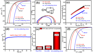
We further evaluated the HER electrocatalytic activity of all the catalysts in the same 1 M KOH solution using the same three-electrode setup. The LSV outcomes (60% iR compensation) given in Fig. 6a show that NiCo-LDH@NH2-UiO-66 exhibits the highest catalytic activity with a lower overpotential of 224 mV than NiCo-LDH (281 mV) and NH2-UiO-66 (292 mV) to reach a 50 mA cm−2 current density. Besides, the commercial Pt/C shows high electrocatalytic activity with an overpotential of 132 mV to reach the same current density (50 mA cm−2).51 Moreover, the analyzed pH-dependent electrocatalytic activity of the NiCo-LDH@NH2-UiO-66 catalyst at four different pHs of KOH (Fig. S16†) disclosed the reduction of catalytic activity with the decrease in pH of KOH. Besides, the obtained overpotential for pH ∼ 14, 13.6, 13.4, and 13.0 was 224, 292, 303, and 324 mV to attain the same current density of 50 mA cm−2.The higher electrocatalytic activity of NiCo-LDH@NH2-UiO-66 towards the HER might be due to the moderate adsorption/desorption of H* than the bare NH2-UiO-66 and NiCo-LDH materials. However, the EIS analysis in Fig. 6b shows that hybrid NiCo-LDH@NH2-UiO-66 possesses less resistance with an Rct value of 0.49 Ω towards the charge transfer at the electrode–electrolyte interface than the NiCo-LDH (0.58 Ω) and NH2-UiO-66 (0.61 Ω). The LSV-derived Tafel slope outcomes in Fig. 6c suggest that the NiCo-LDH@NH2-UiO-66 hybrid displays a lower Tafel slope of 82 mV dec−1, whereas NiCo-LDH and NH2-UiO-66 require 88 and 92 mV dec−1 as Tafel values, respectively. Tafel slope outcomes further confirm that the formation of the heterostructure between NH2-UiO-66 and NiCo-LDH facilitates the faster charge transfer at the interface, which further enhances the activity of NiCo-LDH@NH2-UiO-66 by reducing the overpotential. The long-term chronoamperometric analysis in Fig. 6d revealed the highly stable nature of the NiCo-LDH@NH2-UiO-66 electrocatalyst up to 30 h at an applied potential of −0.33 V (vs. RHE). In addition, the chronocoulometric analysis results revealed that the continuous accumulation of charge over the catalyst is unceasing at a certain applied potential for 2 h, which can be evident from the straight line as shown in Fig. S17.† These results again confirm the stable nature of the catalyst NiCo-LDH@NH2-UiO-66. To know the number of hydrogen molecules evolved per second, TOF values are calculated at 275 mV overpotential, and the respective bar diagram is given in Fig. 6e. The bar diagram showed that the NiCo-LDH@NH2-UiO-66 hybrid exhibits a higher TOF value of 0.47453, as expected which is higher than that of the NiCo-LDH (0.10548 × 10³ s−1) and NH2-UiO-66 (0.08452 × 10³ s−1), suggesting that NiCo-LDH@NH2-UiO-66 evolves a larger number of hydrogen molecules per second than the other catalyst. The mass-dependent normalization with the catalyst loading given in Table S3† of all the catalysts follows the same activity trend with an overpotential of 228, 283, and 293 mV corresponding to NiCo-LDH@NH2-UiO-66, NiCo-LDH, and NH2-UiO-66 respectively (Fig. 6f). Moreover, Fig. S18a† shows the LSV results of NiCo-LDH@NH2-UiO-66 after 1000 continuous CV cycles, which depicted the hike in the overpotential with a difference of 15 mV than the one achieved before 1000 CV cycles suggesting the high dynamic stability over the HER process. EIS analysis also displayed the same with an Rct of (0.55 Ω) which is higher than the one obtained before cycling (Fig. S18b†). Moreover, the obtained results of HER activities are comparable with the reported catalyst in the literature and provided in Table S5.†
Total water splitting (TWS) performance of the NiCo-LDH@NH2-UiO-66 electrode
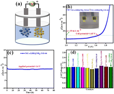
Inspired by the higher electrocatalytic activity of the NiCo-LDH@NH2-UiO-66 electrode towards the HER and OER in an alkaline medium, we demonstrate a full cell in the same 1 M KOH solution. However, we employed NiCo-LDH@NH2-UiO-66 as both the cathode and anode (bifunctional catalyst; NiCo-LDH@NH2-UiO-66 || NiCo-LDH@NH2-UiO-66) for total water splitting (Fig. 7a). Interestingly, NiCo-LDH@NH2-UiO-66 || NiCo-LDH@NH2-UiO-66 requires a cell voltage of 1.65 V to split water molecules at a benchmarking current density of 10 mA cm−2 (Fig. 7b). Notably, NiCo-LDH@NH2-UiO-66 || NiCo-LDH@NH2-UiO-66 shows remarkable operating stability for 78 h with no obvious reduction from the initial current density at an applied potential of 1.6 V as seen from Fig. 7c. Our bifunctional electrocatalyst cell voltage is comparable to the majority of previously reported bifunctional electrocatalysts (Fig. 7d). The process of total water splitting in the alkaline environment is given as ESI† video. The above obtained best activity explains that NiCo-LDH@NH2-UiO-66 will be a potential candidate for the total water-splitting reaction.Moreover, after 1000 continuous CV cycles of NiCo-LDH@NH2-UiO-66 towards the OER and HER, the chemical nature and morphology were analysed through XRD, FE-SEM, and XPS techniques. In the XRD pattern (Fig. S19†), no characteristic peaks corresponding to NiCo-LDH@NH2-UiO-66 were observed other than the nickel peak. In addition, Fig. S20(a–d)† represents the FE-SEM analysis of NiCo-LDH@NH2-UiO-66 after OER and HER analyses. These results show that after continuous CV cycles the morphology of NiCo-LDH@NH2-UiO-66 was intact, suggesting the highly stable nature of the catalyst in 1 M KOH solution. Further, the XPS analysis of NiCo-LDH@NH2-UiO-66 after OER and HER analysis was carried out, and the obtained spectrum is presented in Fig. S21a–g.† The XPS survey spectrum in Fig. S21a† shows the presence of all the expected elements like Zr 3d, Co 2p, Ni 2p, N 1s, C 1s and O 1s even after the OER and HER analysis. The deconvoluted Co 2p XPS spectrum (Fig. S21c†) shows that after OER and HER analysis the Co 2p3/2 peaks are shifted towards lower binding (0.89 and 0.94 eV for the OER and HER, respectively) which might have originated due to the increase of the Co3+ state during OER and HER analysis. The above results suggest that Co has served as the active sites for both reactions and further prove the highly stable nature of NiCo-LDH@NH2-UiO-66 after the continuous 1000 CV cycles in 1 M KOH solution.
DFT calculations
The free energy of hydrogen adsorption (GH*) can be a good indicator of the activity of H2 evolution. The HER activity can be determined from the free energy profile. There are a total of three steps, involved in the calculation of the free energy profile. The first (GH+) and final are anticipated as in equilibrium conditions considering the computational hydrogen electrode concept. Although, hydrogen adsorption (H*) is the key step to define the evolution of H2, it is defined as the second step in the free energy profile. The Gibbs free energy is calculated by using the following equation ΔGH = ΔE − TΔS + ZPE, where ΔE represents the difference in total energy (calculated from DFT), and ΔS and ZPE imply the gradient in entropy and the zero-point energy difference between the adsorbed and the gas phase of hydrogen, respectively.52 However, ΔS and ZPE of the adsorbed hydrogen are considered negligible and ignored as compared to those obtained for the gaseous phase under ambient conditions.
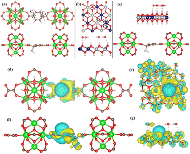
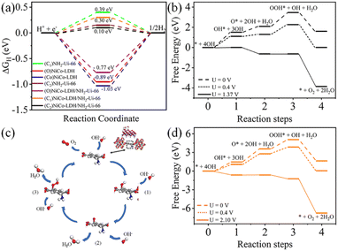
To confirm the experimental finding and to define the HER activity, we have used DFT-based calculation to evaluate the ΔGH. In this work, we have considered three model structures namely, (i) NiCo-LDH (Fig. 8b) (R3M-space group), (ii) NH2-UiO-66 (Fig. 8a), and (iii) NiCo-LDH@NH2-UiO-66 as shown in Fig. 8c. To build the NiCo-LDH@NH2-UiO-66 heterostructure, we have considered a (2 × 1 × 1) supercell of the alpha phase of the NiCo-LDH structure and NH2-UiO-66 structure where two metal clusters are separated by a carbon ring, which is named NiCo-LDH@NH2-UiO-66. First, we have estimated the GH* for NiCo-LDH, where we have defined two active sites for hydrogen adsorption, (i) Co–NiCo-LDH and (ii) O–NiCo-LDH as shown in Fig. 8b. The GH* for Co–NiCo-LDH and O–NiCo-LDH is −1.03 eV and −0.89 eV, respectively, which shows the strong binding of hydrogen to the surface. The estimated GH* for the Co–NiCo-LDH site is well matched with the previous report.53 From Bader charge analysis and charge density difference, it is confirmed that a total 0.72 e charge is transferred to the LDH surface, where Co and O atoms gain 0.38 e and 0.42 e, respectively. The charge density plot for hydrogen adsorbed at the Co site of NiCo-LDH is shown in Fig. 8(f and g). Next, we have estimated the hydrogen adsorption on the NH2-UiO-66 surface. For NH2-UiO-66 (Zr-MOF), we have defined two active sites, C1 and C2, where the C1 site is not surrounded by any molecule and the C2 site is surrounded by NH2 molecules as shown in Fig. 8a. The estimated GH* for C1 and C2 site is 0.39 eV and 0.15 eV, respectively. Further, charge density difference and Bader charge analysis show negligible charge transfer from the H atom to the C atom (Fig. 8d and e). For MOF at both sites, the H atom loses 0.12 e and the C atom gains the same charge. In the case of the NiCo-LDH@NH2-UiO-66 heterostructure, we have considered three H adsorption sites, C1 and C2 sites of NH2-UiO-66 and the O site of the NiCo-LDH structure. The calculated H2 adsorption energies for the C1, C2, and O sites of NiCo-LDH@NH2-UiO-66 are 0.30 eV, 0.10 eV, and −0.77 eV, respectively. We have calculated the Bader charge for the most efficient site C2 of the NiCo-LDH@NH2-UiO-66 structure for HER activity. In this case, H loses 0.10 e charge whereas C gains the same charge, and the charge density difference for C2 of the NiCo-LDH@NH2-UiO-66 structure also confirms that H loses the charge, which accumulates towards the C site. From the complete free energy profile, as shown in Fig. 9a and Bader charge analysis, we can conclude that NiCo-LDH@NH2-UiO-66 is an efficient catalyst for H2 production.
After theoretical confirmation of a favourable site for HER activity, we analyzed the electrochemical performance towards the OER and estimated the associated overpotential (η) through a complete OER-free energy profile. There are a total of three intermediate steps associated with the OER free energy profile: (i) ΔGOH*, (ii) ΔGO*, and (iii) ΔGOOH*.54,55 The adsorption energy of OH and OOH at particular sites is linearly dependent and correlates with the adsorption strength of the O atom. The change in free energy of O, OH, and OOH is calculated using the relation:
respectively. Here, GO(NiCo-LDH@NH2-UiO-66), GOH(NiCo-LDH@NH2-UiO-66), and GOOH(NiCo-LDH@NH2-UiO-66) represent the Gibbs free energy of O, OH, and OOH, respectively. With this, we have calculated the complete OER free energy for C1 and C2 of the NiCo-LDH@NH2-UiO-66 structure. In the case of the C2 site of the NiCo-LDH@NH2-UiO-66 structure, we have observed that the difference between ΔGOOH − ΔGO is determined as the potential determining step with a maximum uphill at U = 0. The estimated η for the C2 site of the NiCo-LDH@NH2-UiO-66 structure is about 0.96 eV at equilibrium potential (U = 0.4), requiring 1.37 eV onset potential to perform the reaction as shown in Fig. 9b. But in the case of the C1 site of the NiCo-LDH@NH2-UiO-66 structure, ΔGOH − ΔGO can be determined as the potential determining step with a maximum uphill at U = 0. The predicted η is 1.71 eV and the required onset potential is 2.1 eV to perform the reaction. The complete OER energy profile for C1 of the NiCo-LDH@NH2-UiO-66 structure is shown in Fig. 9d. The schematic diagram of the OER is shown in Fig. 9c. Overall, from theoretical observation, the NiCo-LDH@NH2-UiO-66 structure can be used as an ideal catalyst for the HER as well as OER.
Conclusions
In conclusion, the present investigation has demonstrated the first example of a 2-methyl imidazole-derived ultrathin 2D NiCo-LDH nanosheet array anchored via in situ growth on the NH2-UiO-66 octahedron surface for efficient electrocatalytic OER and HER. Surface and bulk characterization (employing, e.g., electron microscopy, AFM, X-ray-based techniques, Raman, FT-IR, BET, etc.) of the as-prepared composite confirms the successful linkage of the individual components and retention of the structural integrity. NiCo-LDH@NH2-UiO-66 bifunctional electrocatalysts showed exceptional stability and enhanced overall efficiency of H2O splitting in an alkaline medium. The marvelous electrocatalytic efficiency is ascribed to the following contributing factors: (1) in situ NiCo-LDH growth over the MOF substrate alongside improving structural stability and conductivity, also endowed rapid charge transfer and bubble release; (2) its intricate morphological features provide higher specific surface area, largely accessible exposed sites and improved charge/mass dynamics; (3) extensive symbiotic relationship between NH2-UiO-66 and NiCo-LDH explains the advanced electrochemical performance towards HER and OER processes. We also believe that combining charge-carrier dynamic analysis with DFT calculations exposed both the exclusive spatial coordination structure and electronic properties of ultrathin 2D NiCo-LDH sites and the strong metal-support interface effect on NH2-UiO-66, the main reasons for achieving the significantly enhanced electrocatalytic performance. This report is the first example of decorating ultrathin 2D LDH nanosheets on a MOF as a robust non-noble bifunctional electrocatalyst for renewable energy conversion applications, and further in-depth studies of related materials are in progress.Conflicts of interest
There are no conflicts to declare.Acknowledgements
This work was supported by the DST HFC research grants (project No: DST/TMD/HFC/2K18/60/(C)/3) Government of India's financial support. S. Sk and M. R. thank AcSIR for Ph.D. enrolment. The authors are also grateful to CSIR-IICT (IICT/Pubs./2022/239) for support. R. T. thanks the National Supercomputer Mission (NSM), India for financial support (Ref. No. DST/NSM/R&D-HPC-Applications/2021/19) and Science and Engineering Research Board (SERB), India, for financial support (Grant No. CRG/2021/000620). The authors thank the High-Performance Computing Centre, SRM University-AP, India, for providing the central computational facility. S. Kundu also wishes to acknowledge DST for HFC research funding #DST/TMD/HFC/2K18/60/(C)/2 with institute OM number 18-29-03/(31/19)-TTBD-CSIR-CECRI on 24/10/2019.Notes and references
- N. S. Lewis and D. G. Nocera, Proc. Natl. Acad. Sci., 2006, 103, 15729–15735 CrossRef CAS PubMed.
- H. B. Gray, Nat. Chem., 2009, 1, 7 CrossRef CAS PubMed.
- A. Gautam, S. Sk and U. Pal, Phys. Chem. Chem. Phys., 2022, 24, 20638–20673 RSC.
- A. Govind Rajan, J. M. P. Martirez and E. A. Carter, ACS Catal., 2020, 10, 11177–11234 CrossRef CAS.
- B. Xiong, L. Chen and J. Shi, ACS Catal., 2018, 8, 3688–3707 CrossRef CAS.
- C.-Z. Yuan, K. S. Hui, H. Yin, S. Zhu, J. Zhang, X.-L. Wu, X. Hong, W. Zhou, X. Fan, F. Bin, F. Chen and K. N. Hui, ACS Mater. Lett., 2021, 3, 752–780 CrossRef CAS.
- V.-H. Do and J.-M. Lee, ACS Nano, 2022, 16, 17847–17890 CrossRef CAS PubMed.
- Y. Yan, T. He, B. Zhao, K. Qi, H. Liu and B. Y. Xia, J. Mater. Chem. A, 2018, 6, 15905–15926 RSC.
- S. Sk, I. Mondal, A. Mahata, B. M. Abraham, C. Nayak, D. Bhattacharyya, S. N. Jha, R. Ghosh and U. Pal, ACS Appl. Energy Mater., 2022, 5, 12324–12335 CrossRef CAS.
- W. Wang, X. Xu, W. Zhou and Z. Shao, Adv. Sci., 2017, 4, 1600371 CrossRef PubMed.
- D. Senthil Raja, X.-F. Chuah and S.-Y. Lu, Adv. Energy Mater., 2018, 8, 1801065 CrossRef.
- S. Sk, C. S. Vennapoosa, A. Tiwari, B. M. Abraham, M. Ahmadipour and U. Pal, Int. J. Hydrogen Energy, 2022, 47, 33955–33965 CrossRef CAS.
- D. P. Sahoo, K. K. Das, S. Mansingh, S. Sultana and K. Parida, Coord. Chem. Rev., 2022, 469, 214666 CrossRef CAS.
- A. Hameed, M. Batool, Z. Liu, M. A. Nadeem and R. Jin, ACS Energy Lett., 2022, 7, 3311–3328 CrossRef CAS.
- Y. Liu, Y. Bai, W. Yang, J. Ma and K. Sun, Electrochim. Acta, 2021, 367, 137534 CrossRef CAS.
- R. Que, S. Liu, Y. Yang and Y. Pan, Mater. Lett., 2021, 288, 129364 CrossRef CAS.
- J. Yan, L. Chen and X. Liang, Sci. Bull., 2019, 64, 158–165 CrossRef CAS PubMed.
- X. Xu, L. Su, Y. Zhang, L. Dong and X. Miao, New J. Chem., 2021, 45, 15429–15436 RSC.
- X. Xu, W. Zhong, L. Zhang, G. Liu, W. Xu, Y. Zhang and Y. Du, Surf. Coat. Technol., 2020, 397, 126065 CrossRef CAS.
- L. Zhang, J. Peng, Y. Yuan, W. Zhang and K. Peng, Appl. Surf. Sci., 2021, 557, 149831 CrossRef CAS.
- L. Jia, G. Du, D. Han, Y. Hao, W. Zhao, Y. Fan, Q. Su, S. Ding and B. Xu, J. Mater. Chem. A, 2021, 9, 27639–27650 RSC.
- H. N. Dhandapani, D. Mahendiran, A. Karmakar, P. Devi, S. Nagappan, R. Madhu, K. Bera, P. Murugan, B. R. Babu and S. Kundu, J. Mater. Chem. A, 2022, 10, 17488–17500 RSC.
- K. Bera, A. Karmakar, S. Kumaravel, S. Sam Sankar, R. Madhu, H. N Dhandapani, S. Nagappan and S. Kundu, Inorg. Chem., 2022, 61, 4502–4512 CrossRef CAS PubMed.
- T. Wang, S. Zhang, X. Yan, M. Lyu, L. Wang, J. Bell and H. Wang, ACS Appl. Mater. Interfaces, 2017, 9, 15510–15524 CrossRef CAS.
- D. Zhao, Y. Wang, C.-L. Dong, Y.-C. Huang, J. Chen, F. Xue, S. Shen and L. Guo, Nat. Energy, 2021, 6, 388–397 CrossRef CAS.
- J. Ran, H. Zhang, S. Fu, M. Jaroniec, J. Shan, B. Xia, Y. Qu, J. Qu, S. Chen, L. Song, J. M. Cairney, L. Jing and S.-Z. Qiao, Nat. Commun., 2022, 13, 4600 CrossRef CAS PubMed.
- L. Xu, Y.-S. Ding, C.-H. Chen, L. Zhao, C. Rimkus, R. Joesten and S. L. Suib, Chem. Mater., 2008, 20, 308–316 CrossRef CAS.
- J. Jiang, A. Zhang, L. Li and L. Ai, J. Power Sources, 2015, 278, 445–451 CrossRef CAS.
- R. Fan, Q. Mu, Z. Wei, Y. Peng and M. Shen, J. Mater. Chem. A, 2020, 8, 9871–9881 RSC.
- K. Sun, M. Liu, J. Pei, D. Li, C. Ding, K. Wu and H.-L. Jiang, Angew. Chem., Int. Ed., 2020, 59, 22749–22755 CrossRef CAS PubMed.
- H. Zhang, X. Shi, J. Li, P. Kumar and B. Liu, Nanomaterials, 2019, 9, 1283 CrossRef CAS PubMed.
- S. Chavan, J. G. Vitillo, M. J. Uddin, F. Bonino, C. Lamberti, E. Groppo, K.-P. Lillerud and S. Bordiga, Chem. Mater., 2010, 22, 4602–4611 CrossRef CAS.
- L. Shen, S. Liang, W. Wu, R. Liang and L. Wu, Dalton Trans., 2013, 42, 13649–13657 RSC.
- A. Helal, M. Qamaruddin, M. A. Aziz, M. N. Shaikh and Z. H. Yamani, ChemistrySelect, 2017, 2, 7630–7636 CrossRef CAS.
- C. Yu, J. Yang, C. Zhao, X. Fan, G. Wang and J. Qiu, Nanoscale, 2014, 6, 3097–3104 RSC.
- R. Li, Z. Hu, X. Shao, P. Cheng, S. Li, W. Yu, W. Lin and D. Yuan, Sci. Rep., 2016, 6, 18737 CrossRef CAS PubMed.
- H. Chen, L. Hu, M. Chen, Y. Yan and L. Wu, Adv. Funct. Mater., 2014, 24, 934–942 CrossRef CAS.
- F. Meng, Y. Qin, J. Lu, X. Lin, M. Meng, G. Sun and Y. Yan, J. Colloid Interface Sci., 2021, 584, 464–473 CrossRef CAS PubMed.
- Q. Pan, F. Zheng, D. Deng, B. Chen and Y. Wang, ACS Appl. Mater. Interfaces, 2021, 13, 56692–56703 CrossRef CAS PubMed.
- A. Garcia-Gallastegui, D. Iruretagoyena, M. Mokhtar, A. M. Asiri, S. N. Basahel, S. A. Al-Thabaiti, A. O. Alyoubi, D. Chadwick and M. S. P. Shaffer, J. Mater. Chem., 2012, 22, 13932–13940 RSC.
- M. Li, J. P. Cheng, F. Liu and X. B. Zhang, Chem. Phys. Lett., 2015, 640, 5–10 CrossRef CAS.
- T. He, X. Xu, B. Ni, H. Wang, Y. Long, W. Hu and X. Wang, Nanoscale, 2017, 9, 19209–19215 RSC.
- G. C. Shearer, S. Chavan, S. Bordiga, S. Svelle, U. Olsbye and K. P. Lillerud, Chem. Mater., 2016, 28, 3749–3761 CrossRef CAS.
- X. Fang, S. Wu, Y. Wu, W. Yang, Y. Li, J. He, P. Hong, M. Nie, C. Xie, Z. Wu, K. Zhang, L. Kong and J. Liu, Appl. Surf. Sci., 2020, 518, 146226 CrossRef CAS.
- F. Yang, S. Xie, G. Wang, C. W. Yu, H. Liu and Y. Liu, Environ. Sci. Pollut. Res., 2020, 27, 20246–20258 CrossRef CAS PubMed.
- J. Acharya, T. H. Ko, M.-K. Seo, M.-S. Khil, H.-Y. Kim and B.-S. Kim, ACS Appl. Energy Mater., 2020, 3, 7383–7396 CrossRef CAS.
- J. An, T. Shen, W. Chang, Y. Zhao, B. Qi and Y.-F. Song, Inorg. Chem. Front., 2021, 8, 996–1004 RSC.
- J. Xu, S. He, H. Zhang, J. Huang, H. Lin, X. Wang and J. Long, J. Mater. Chem. A, 2015, 3, 24261–24271 RSC.
- M. Zhang, Z. Luo, M. Zhou, G. Zhang, K. A. Alamry, L. A. Taib, A. M. Asiri and X. Wang, Appl. Catal., B, 2017, 210, 454–461 CrossRef CAS.
- S. Li, L. Wang, Y. Li, L. Zhang, A. Wang, N. Xiao, Y. Gao, N. Li, W. Song, L. Ge and J. Liu, Appl. Catal., B, 2019, 254, 145–155 CrossRef CAS.
- R. Madhu, R. Jayan, A. Karmakar, S. S. Selvasundarasekar, S. Kumaravel, K. Bera, S. Nagappan, H. N Dhandapani, M. M. Islam and S. Kundu, ACS Sustainable Chem. Eng., 2022, 10, 11299–11309 CrossRef CAS.
- A. Tiwari, A. Gautam, S. Sk, D. S. Gavali, R. Thapa and U. Pal, J. Phys. Chem. C, 2021, 125, 11950–11962 CrossRef CAS.
- G. Chen, T. Wang, J. Zhang, P. Liu, H. Sun, X. Zhuang, M. Chen and X. Feng, Adv. Mater., 2018, 30, 1706279 CrossRef PubMed.
- S. Kapse, S. Janwari, U. V. Waghmare and R. Thapa, Appl. Catal., B, 2021, 286, 119866 CrossRef CAS.
- I. C. Man, H.-Y. Su, F. Calle-Vallejo, H. A. Hansen, J. I. Martínez, N. G. Inoglu, J. Kitchin, T. F. Jaramillo, J. K. Nørskov and J. Rossmeisl, ChemCatChem, 2011, 3, 1159–1165 CrossRef CAS.
Footnote |
| † Electronic supplementary information (ESI) available. See DOI: https://doi.org/10.1039/d3ta00836c |
| This journal is © The Royal Society of Chemistry 2023 |

