A novel strategy of constructing an artificial light-harvesting system based on a supramolecular organic framework for photocatalysis†
Ying
Wang
,
Chao-Qun
Ma
,
Xin-Long
Li
,
Rui-Zhi
Dong
,
Hui
Liu
,
Rong-Zhou
Wang
,
Shengsheng
Yu
and
Ling-Bao
Xing
 *
*
School of Chemistry and Chemical Engineering, Shandong University of Technology, Zibo 255000, P. R. China. E-mail: lbxing@sdut.edu.cn
First published on 26th January 2023
Abstract
A supramolecular organic framework (SOF) was fabricated based on the tetraphenylethylene derivative MV-TPE with four methylated viologen units, tetraphenylethylene derivative NA-TPE with four methoxynaphthyl units, and cucurbit[8]uril (CB[8]) through encapsulation-enhanced donor–acceptor interaction. When the hydrophobic dye 4,7-bis(thien-2-yl)-2,1,3-benzothiadiazole (DBT) is introduced into the aqueous solution of a SOF, an efficient energy transfer process can take place from the SOF to DBT. In addition, after the addition of amphoteric sulforhodamine 101 (SR101), a two-step sequential energy transfer process can occur from the SOF to DBT and then to SR101. Furthermore, a white emission with the CIE coordinate of (0.31, 0.32) can be realized by the direct addition of SR101 to the SOF. Moreover, to utilize the harvested energy from the SOF + DBT + SR101 system, we tried to apply the SOF-based light-harvesting systems (LHSs) as a catalyst to advance the aerobic cross-dehydrogenative coupling (CDC) reaction in water. To our delight, under the promotion of 0.45 mol% catalyst, the yield of the reaction reached 87%, which exhibited the promising potential of SOF-based LHSs in the promotion of the CDC reaction.
Introduction
Supramolecular organic frameworks (SOFs), which were first constructed in the solution phase by Li et al. in 2013,1 not only have the advantages of periodic pore structure, homogeneous solubility, synthetic diversity, easy synthesis, and functional modification, but also have the intrinsic cavity of the supramolecular large ring with multi-dimensional pores, and have been widely reported in recent years.2–5 Non-covalent interactions, including host–guest interactions,6–11 electrostatic interactions,12,13 coordination interaction,14–16 hydrophobic interactions, and hydrogen bonding,17,18 are the main driving forces during the construction of supramolecular assemblies. Among them, host–guest interaction is commonly used as the driving force for the construction of SOFs due to its high bonding strength.19–23 For example, in 2013, Li et al. reported a SOF with a honeycomb pore driven by the host–guest interaction between CB[8] and 4,4′-bipyridin-1-ium units.1 In 2018, Cao et al. fabricated a two-dimensional (2D) SOF through CB[8]-based host–guest interaction.24In 2001, Kim et al. reported the encapsulation-enhanced donor–acceptor interaction, that is, the hydrophobic cavity of CB[8] can selectively accommodate electron-deficient and electron-rich guests to form a 1![[thin space (1/6-em)]](https://www.rsc.org/images/entities/char_2009.gif) :
:![[thin space (1/6-em)]](https://www.rsc.org/images/entities/char_2009.gif) 1
1![[thin space (1/6-em)]](https://www.rsc.org/images/entities/char_2009.gif) :
:![[thin space (1/6-em)]](https://www.rsc.org/images/entities/char_2009.gif) 1 ternary complex with high stability.25 Based on this classical model, several SOFs have been constructed in these years. For example, in 2015, Feng et al. reported a 2D monolayer SOF based on the encapsulation-enhanced donor–acceptor interaction.26 In 2016, Li et al. reported two single-layer SOFs based on the encapsulation-enhanced donor–acceptor interaction with pH responsiveness.27 The above reports greatly enriched the research of SOFs and aroused people's great research interest.
1 ternary complex with high stability.25 Based on this classical model, several SOFs have been constructed in these years. For example, in 2015, Feng et al. reported a 2D monolayer SOF based on the encapsulation-enhanced donor–acceptor interaction.26 In 2016, Li et al. reported two single-layer SOFs based on the encapsulation-enhanced donor–acceptor interaction with pH responsiveness.27 The above reports greatly enriched the research of SOFs and aroused people's great research interest.
Up to now, there are many reports on the application of SOFs, such as ion and explosive detection,28–30 cell imaging,5,20 visible-light-driven hydrogen evolution,31,32 drug delivery,33 and photodynamic therapy.34,35 However, the application of SOFs still needs to be further expanded. To expand the application of SOFs and effectively utilize the ordered porous structure, water solubility, and luminescence properties of SOFs, we proposed the strategy of employing SOFs to construct artificial light-harvesting systems (LHSs). To date, the construction of artificial LHSs has received extensive attention. In recent years, examples of supramolecular assemblies that were employed to construct artificial LHSs have been widely reported. For example, in 2017, Liu et al. reported an artificial LHS based on nanoparticles through the self-assembly method.36 In 2016, Zhou and co-workers fabricated a highly efficient LHS based on nanotubes constructed through the host–guest interaction.37 However, examples of applying SOFs to construct artificial LHSs have rarely been reported. Therefore, it is a promising method to introduce acceptor dyes into fluorescent SOF systems to construct artificial LHSs. In addition, to fully utilize the energy obtained from artificial LHSs, many reports introduced the application of LHSs in photocatalysis. The artificial LHSs showed good catalytic performance for many photocatalytic reactions, including the cross-coupling hydrogen evolution reaction,38 aerobic cross-dehydrogenative coupling (CDC) reaction,39,40 and the dehalogenation reaction.41 Therefore, it is also innovative to employ SOF-based artificial LHSs as the catalyst to advance photocatalytic reactions.
In this work, a tetraphenylethylene derivative MV-TPE with four methylated viologens (MV) units and a tetraphenylethylene derivative NA-TPE with four methoxynaphthyl units (NA) units were designed and synthesized (Scheme 1). The MV units of MV-TPE and the NA units of NA-TPE can co-encapsulate by the cavity of CB[8] to form a stable three-component SOF. After the SOF is formed, the mixed solution still has a strong emission at 489 nm, which is beneficial to the fabrication of artificial LHSs. After the addition of the acceptor (4,7-bis(thien-2-yl)-2,1,3-benzothiadiazole, DBT), the obvious energy transfer process from the SOF to DBT can be observed. When the ratio of SOF to DBT was 100![[thin space (1/6-em)]](https://www.rsc.org/images/entities/char_2009.gif) :
:![[thin space (1/6-em)]](https://www.rsc.org/images/entities/char_2009.gif) 1, the energy transfer efficiency was determined to be 70.2%. In addition, the second step energy transfer process can be realized by adding the second acceptor (sulforhodamine 101, SR101) into the SOF + DBT system, and the energy transfer efficiency was calculated to be 44.5% (SOF
1, the energy transfer efficiency was determined to be 70.2%. In addition, the second step energy transfer process can be realized by adding the second acceptor (sulforhodamine 101, SR101) into the SOF + DBT system, and the energy transfer efficiency was calculated to be 44.5% (SOF![[thin space (1/6-em)]](https://www.rsc.org/images/entities/char_2009.gif) :
:![[thin space (1/6-em)]](https://www.rsc.org/images/entities/char_2009.gif) DBT
DBT![[thin space (1/6-em)]](https://www.rsc.org/images/entities/char_2009.gif) :
:![[thin space (1/6-em)]](https://www.rsc.org/images/entities/char_2009.gif) SR101 = 300
SR101 = 300![[thin space (1/6-em)]](https://www.rsc.org/images/entities/char_2009.gif) :
:![[thin space (1/6-em)]](https://www.rsc.org/images/entities/char_2009.gif) 3
3![[thin space (1/6-em)]](https://www.rsc.org/images/entities/char_2009.gif) :
:![[thin space (1/6-em)]](https://www.rsc.org/images/entities/char_2009.gif) 20). Interestingly, a bright white light emission (0.31, 0.32) can be obtained by adding SR101 into the solution of SOF directly. Furthermore, the SOF + DBT + SR101 system was used as the catalyst to promote the CDC reaction of N-phenyl tetrahydroisoquinoline and indole. The yield of the model reaction reached 87% after 18 h of UV irradiation, indicating that the SOF + DBT + SR101 system has a good promotion effect on the CDC reaction. And the SOF + DBT + SR101 system also showed a good promotion effect on the reaction of various N-phenyl tetrahydroisoquinoline derivatives and indole derivatives, indicating that this strategy is suitable for promoting a wide range of CDC reactions in water.
20). Interestingly, a bright white light emission (0.31, 0.32) can be obtained by adding SR101 into the solution of SOF directly. Furthermore, the SOF + DBT + SR101 system was used as the catalyst to promote the CDC reaction of N-phenyl tetrahydroisoquinoline and indole. The yield of the model reaction reached 87% after 18 h of UV irradiation, indicating that the SOF + DBT + SR101 system has a good promotion effect on the CDC reaction. And the SOF + DBT + SR101 system also showed a good promotion effect on the reaction of various N-phenyl tetrahydroisoquinoline derivatives and indole derivatives, indicating that this strategy is suitable for promoting a wide range of CDC reactions in water.
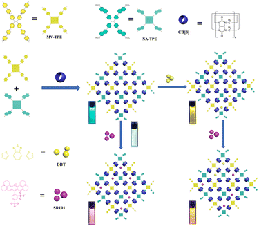 | ||
| Scheme 1 Illustration of the artificial light-harvesting systems based on MV-TPE, NA-TPE, and CB[8]. | ||
Results and discussion
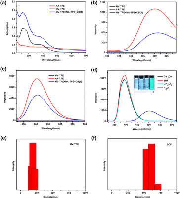
A detailed description of the synthesis and characterization of MV-TPE and NA-TPE is listed in the ESI (Scheme S1, S2 and Fig. S1, S2†). We first investigated the host–guest interaction between MV-TPE, NA-TPE, and CB[8] using UV–vis absorption spectra. Due to the extremely poor solubility of NA-TPE in water, we set the concentration of the sample at 2.0 × 10⁻⁵ M. As shown in Fig. 1a, the absorption curve of MV-TPE showed two absorption peaks at 278 nm and 365 nm, which can be attributed to the absorption of the MV unit and the TPE unit, respectively. NA-TPE has absorption peaks at 320 nm and 365 nm in organic solution solvent and water, respectively (Fig. 1a and S3†). After the addition of NA-TPE and CB[8] (MV-TPE![[thin space (1/6-em)]](https://www.rsc.org/images/entities/char_2009.gif) :
:![[thin space (1/6-em)]](https://www.rsc.org/images/entities/char_2009.gif) NA-TPE
NA-TPE![[thin space (1/6-em)]](https://www.rsc.org/images/entities/char_2009.gif) :
:![[thin space (1/6-em)]](https://www.rsc.org/images/entities/char_2009.gif) CB[8] = 1
CB[8] = 1![[thin space (1/6-em)]](https://www.rsc.org/images/entities/char_2009.gif) :
:![[thin space (1/6-em)]](https://www.rsc.org/images/entities/char_2009.gif) 1
1![[thin space (1/6-em)]](https://www.rsc.org/images/entities/char_2009.gif) :
:![[thin space (1/6-em)]](https://www.rsc.org/images/entities/char_2009.gif) 4), the absorption of the mixed solution was enhanced obviously. This result can be attributed to the charge transfer between the donor (MV unit) and the acceptor (NA unit), which are co-encapsulated by the cavity of CB[8].35 Subsequently, the fluorescence emission spectra of MV-TPE and NA-TPE are also employed to investigate the self-assembly properties of these three compounds. As shown in Fig. 1b and c, MV-TPE has an extremely weak fluorescence emission when excited at 276 nm and 365 nm. In contrast, NA-TPE has strong emission at 350 nm–500 nm in some organic solvents and showed strong blue-green emission at 400 nm–600 nm in water (Fig. 1d). When excited at 276 nm, the mixed solution of MV-TPE, NA-TPE, and CB[8] (MV-TPE
4), the absorption of the mixed solution was enhanced obviously. This result can be attributed to the charge transfer between the donor (MV unit) and the acceptor (NA unit), which are co-encapsulated by the cavity of CB[8].35 Subsequently, the fluorescence emission spectra of MV-TPE and NA-TPE are also employed to investigate the self-assembly properties of these three compounds. As shown in Fig. 1b and c, MV-TPE has an extremely weak fluorescence emission when excited at 276 nm and 365 nm. In contrast, NA-TPE has strong emission at 350 nm–500 nm in some organic solvents and showed strong blue-green emission at 400 nm–600 nm in water (Fig. 1d). When excited at 276 nm, the mixed solution of MV-TPE, NA-TPE, and CB[8] (MV-TPE![[thin space (1/6-em)]](https://www.rsc.org/images/entities/char_2009.gif) :
:![[thin space (1/6-em)]](https://www.rsc.org/images/entities/char_2009.gif) NA-TPE
NA-TPE![[thin space (1/6-em)]](https://www.rsc.org/images/entities/char_2009.gif) :
:![[thin space (1/6-em)]](https://www.rsc.org/images/entities/char_2009.gif) CB[8] = 1
CB[8] = 1![[thin space (1/6-em)]](https://www.rsc.org/images/entities/char_2009.gif) :
:![[thin space (1/6-em)]](https://www.rsc.org/images/entities/char_2009.gif) 1
1![[thin space (1/6-em)]](https://www.rsc.org/images/entities/char_2009.gif) :
:![[thin space (1/6-em)]](https://www.rsc.org/images/entities/char_2009.gif) 4) also has emission at 400 nm–600 nm. However, the emission intensity of the solution is much lower than that of a single NA-TPE at the same concentration (Fig. 1b). This phenomenon may be attributed to the charge transfer process between the electron-rich MV unit and the electron-deficient NA unit since they are both encapsulated in the cavity of CB[8].35,36 The fluorescence spectra of MV-TPE and NA-TPE have also been investigated when excited at 365 nm. As shown in Fig. 1c, under the excitation at 365 nm, the system showed similar fluorescence changes. The fluorescence quantum yield of the NA-TPE in water was determined to be 18.5%. In contrast, the fluorescence quantum yield of the mixed solution (MV-TPE
4) also has emission at 400 nm–600 nm. However, the emission intensity of the solution is much lower than that of a single NA-TPE at the same concentration (Fig. 1b). This phenomenon may be attributed to the charge transfer process between the electron-rich MV unit and the electron-deficient NA unit since they are both encapsulated in the cavity of CB[8].35,36 The fluorescence spectra of MV-TPE and NA-TPE have also been investigated when excited at 365 nm. As shown in Fig. 1c, under the excitation at 365 nm, the system showed similar fluorescence changes. The fluorescence quantum yield of the NA-TPE in water was determined to be 18.5%. In contrast, the fluorescence quantum yield of the mixed solution (MV-TPE![[thin space (1/6-em)]](https://www.rsc.org/images/entities/char_2009.gif) :
:![[thin space (1/6-em)]](https://www.rsc.org/images/entities/char_2009.gif) NA-TPE
NA-TPE![[thin space (1/6-em)]](https://www.rsc.org/images/entities/char_2009.gif) :
:![[thin space (1/6-em)]](https://www.rsc.org/images/entities/char_2009.gif) CB[8] = 1
CB[8] = 1![[thin space (1/6-em)]](https://www.rsc.org/images/entities/char_2009.gif) :
:![[thin space (1/6-em)]](https://www.rsc.org/images/entities/char_2009.gif) 1
1![[thin space (1/6-em)]](https://www.rsc.org/images/entities/char_2009.gif) :
:![[thin space (1/6-em)]](https://www.rsc.org/images/entities/char_2009.gif) 4) was determined to be 7.5%, which is consistent with fluorescence measurements.
4) was determined to be 7.5%, which is consistent with fluorescence measurements.
The dynamic light scattering (DLS) experiments were then performed in water to investigate the self-assembly process. As shown in Fig. 1e and f, the hydrodynamic diameter (DH) values of the solution of MV-TPE in water were determined to be about 200 nm. After the addition of 1 equiv. NA-TPE and 4 equiv. CB[8], a larger size structure with an average diameter of about 600 nm was detected, which indicates that a three-component SOF with a larger size structure was successfully assembled. And the DH value of the SOF increases with increasing concentration of the solution (Fig. S4†). Furthermore, the mixed solution of MV-TPE, NA-TPE, and CB[8] also exhibited higher zeta potential than that of the solution of MV-TPE (Fig. S5†).
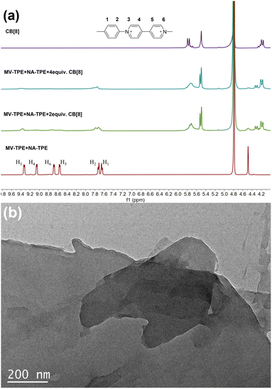
1H NMR titration experiments were further used to prove the assembly process between MV-TPE, NA-TPE, and CB[8]. Fig. 2a shows the changes in the 1H NMR spectra of MV-TPE and NA-TPE in D2O with an increasing amount of CB[8]. Due to the low resolution of NA-TPE in D2O, almost no change in the spectra of MV-TPE was observed. However, after the addition of 2 equiv. of CB[8] in the mixed solution of MV-TPE and NA-TPE in D2O, the signals of MV units of MV-TPE shift downfield and the peaks of MV units are significantly broadened. When the amount of CB[8] is increased to 4 equiv., the signals of the MV unit continue to shift downfield and the signals of H4–6 protonated disappeared completely, which indicates that the binding ratio of MV-TPE, NA-TPE, and CB[8] was 1![[thin space (1/6-em)]](https://www.rsc.org/images/entities/char_2009.gif) :
:![[thin space (1/6-em)]](https://www.rsc.org/images/entities/char_2009.gif) 1
1![[thin space (1/6-em)]](https://www.rsc.org/images/entities/char_2009.gif) :
:![[thin space (1/6-em)]](https://www.rsc.org/images/entities/char_2009.gif) 4. In addition, transmission electron microscopy (TEM) was performed in water to investigate the self-assembly structure of the SOF. As shown in Fig. 2b, a complete large-size sheet structure can be observed clearly. The above results proved that the three-component SOF was successfully obtained through the self-assembly between MV-TPE, NA-TPE, and CB[8].
4. In addition, transmission electron microscopy (TEM) was performed in water to investigate the self-assembly structure of the SOF. As shown in Fig. 2b, a complete large-size sheet structure can be observed clearly. The above results proved that the three-component SOF was successfully obtained through the self-assembly between MV-TPE, NA-TPE, and CB[8].
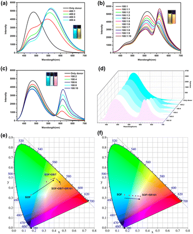
Although the emission of the SOF in water is lower than that of NA-TPE, there is still strong emission at 450 nm–600 nm. In addition, the formation of the SOF significantly improves the solubility of NA-TPE in water. The fluorescence quantum yield of the SOF in water was determined to be 7.5%, which indicates that it can be used as a suitable platform to construct artificial LHSs. Hydrophobic fluorescent dye DBT has a wide absorption range from 390 nm to 600 nm, which greatly overlaps with the emission region of the SOF (450 nm–600 nm), and can be used as a suitable energy acceptor to fabricate an artificial LHS (Fig. S6a†). As shown in Fig. 3a, with the continuous addition of DBT, the emission of the SOF at 487 nm gradually decreased. The emission of DBT at 558 nm gradually increased with the addition of DBT. When the molar ratio of SOF![[thin space (1/6-em)]](https://www.rsc.org/images/entities/char_2009.gif) :
:![[thin space (1/6-em)]](https://www.rsc.org/images/entities/char_2009.gif) DBT = 100
DBT = 100![[thin space (1/6-em)]](https://www.rsc.org/images/entities/char_2009.gif) :
:![[thin space (1/6-em)]](https://www.rsc.org/images/entities/char_2009.gif) 1, the emission color of the mixed solution was changed from cyan to yellow through the naked eye. And the CIE coordinate diagram also shows similar fluorescence changes (Fig. 3e). The energy transfer efficiency and the antenna effect of the energy transfer process from the SOF to DBT were calculated to be 70.2% and 12.3, respectively, which proved that the energy transfer process between the SOF and DBT is quite efficient among the most reported LHSs (Fig. S8a and S9a†).
1, the emission color of the mixed solution was changed from cyan to yellow through the naked eye. And the CIE coordinate diagram also shows similar fluorescence changes (Fig. 3e). The energy transfer efficiency and the antenna effect of the energy transfer process from the SOF to DBT were calculated to be 70.2% and 12.3, respectively, which proved that the energy transfer process between the SOF and DBT is quite efficient among the most reported LHSs (Fig. S8a and S9a†).
In recent years, the construction of a two-step sequential energy transfer LHS has been reported, which has attracted the most research interest. Therefore, we tried to realize the second energy transfer by introducing the second acceptor (SR101) into the SOF + DBT system. As shown in Fig. S6b and 3b,† due to the good spectral overlap between the emission of SOF + DBT and SR101, an efficient sequential energy transfer occurred from the SOF to DBT and then to SR101. The energy transfer efficiency of the second energy transfer was 44.5% and the antenna effect was 1.8 (Fig. S8b and S9b,† SOF![[thin space (1/6-em)]](https://www.rsc.org/images/entities/char_2009.gif) :
:![[thin space (1/6-em)]](https://www.rsc.org/images/entities/char_2009.gif) DBT
DBT![[thin space (1/6-em)]](https://www.rsc.org/images/entities/char_2009.gif) :
:![[thin space (1/6-em)]](https://www.rsc.org/images/entities/char_2009.gif) SR101 = 100
SR101 = 100![[thin space (1/6-em)]](https://www.rsc.org/images/entities/char_2009.gif) :
:![[thin space (1/6-em)]](https://www.rsc.org/images/entities/char_2009.gif) 1
1![[thin space (1/6-em)]](https://www.rsc.org/images/entities/char_2009.gif) :
:![[thin space (1/6-em)]](https://www.rsc.org/images/entities/char_2009.gif) 10), and the emission color of the mixed solution was changed from yellow to orange through the naked eye. In addition, the energy transfer between the SOF and SR101 was also investigated. There is a small overlap between the emission of the SOF and the absorption of SR101 (Fig. S7†). As shown in Fig. 3c, with the direct addition of SR101 to the SOF, the energy transfer process between the SOF and SR101 can be observed. When the ratio of SOF and SR101 is 10
10), and the emission color of the mixed solution was changed from yellow to orange through the naked eye. In addition, the energy transfer between the SOF and SR101 was also investigated. There is a small overlap between the emission of the SOF and the absorption of SR101 (Fig. S7†). As shown in Fig. 3c, with the direct addition of SR101 to the SOF, the energy transfer process between the SOF and SR101 can be observed. When the ratio of SOF and SR101 is 10![[thin space (1/6-em)]](https://www.rsc.org/images/entities/char_2009.gif) :
:![[thin space (1/6-em)]](https://www.rsc.org/images/entities/char_2009.gif) 1, the energy transfer efficiency was calculated to be 21.5%, which is much lower than the result between the SOF and DBT. This may be due to the poor energy matching between the emission of the SOF and the absorption of SR101 (Fig. S7†). More importantly, during the titration, the CIE coordinates of the SOF + SR101 system pass through the white light region (0.31, 0.32), which is close to the CIE coordinates of standard white light (0.33, 0.33) (Fig. 3f). A bright white light emission can be obtained by adjusting the ratio between the SOF and SR101 (Fig. 3d, SOF
1, the energy transfer efficiency was calculated to be 21.5%, which is much lower than the result between the SOF and DBT. This may be due to the poor energy matching between the emission of the SOF and the absorption of SR101 (Fig. S7†). More importantly, during the titration, the CIE coordinates of the SOF + SR101 system pass through the white light region (0.31, 0.32), which is close to the CIE coordinates of standard white light (0.33, 0.33) (Fig. 3f). A bright white light emission can be obtained by adjusting the ratio between the SOF and SR101 (Fig. 3d, SOF![[thin space (1/6-em)]](https://www.rsc.org/images/entities/char_2009.gif) :
:![[thin space (1/6-em)]](https://www.rsc.org/images/entities/char_2009.gif) SR101 = 100
SR101 = 100![[thin space (1/6-em)]](https://www.rsc.org/images/entities/char_2009.gif) :
:![[thin space (1/6-em)]](https://www.rsc.org/images/entities/char_2009.gif) 8). The result proves that the SOF + SR101 system can be employed as a white light-emitting material with potential application value.
8). The result proves that the SOF + SR101 system can be employed as a white light-emitting material with potential application value.
To investigate the potential application value of the SOF + DBT + SR101 system, we try to use the harvested energy obtained by the artificial LHS to catalyze the organic reactions. The aerobic CDC reaction promoted by noble-metal catalysts is commonly reported in recent years. However, noble metal catalysts are often expensive and difficult to synthesize. Therefore, it is meaningful to realize the promotion of the CDC reaction by metal-free catalysts. Therefore, we attempt to apply the SOF + DBT + SR101 system as a catalyst for the aerobic CDC reaction in water. The UV lamp was selected as the excitation source, and the reaction was irradiated in water under air conditions for 18 h. As shown in Table S1,† with the participation of a 0.45 mol% catalytic system, the yield of the reaction reached 87%, which indicates that the SOF + DBT + SR101 system has a good catalytic effect on the CDC reaction. By comparison, as shown in Table 1, the yield of the reaction promoted by the SOF was only 50%, which indicates that SOF has a much poor catalytic effect than the SOF + DBT + SR101 system without the participation of the dyes. The efficient two-step energy transfer process greatly improves the light-use efficiency, leading to a significant increase in reaction yield. The yields of the reaction catalyzed by DBT and SR101 are 30% and 41%, which are much lower than those of the SOF + DBT + SR101 group. In addition, the CDC reaction was also carried out under a N2 atmosphere and the yield was extremely low, which indicates the importance of the participation of O2.
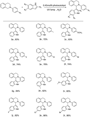
To investigate the universality of the SOF + DBT + SR101 system as a photocatalyst to promote the CDC reaction in an aqueous solution, various substrates were employed to carry out the CDC reaction. The yields of the reaction were determined by the 1H NMR of the reaction system in CDCl3 (Fig. S10–S21†). As shown in Table 2, the N-phenyl tetrahydroisoquinoline derivatives bearing electron-donating groups (–CH3 and –OCH3) can achieve high yields (72% for 3b and 83% for 3c), and the N-phenyl tetrahydroisoquinoline derivatives bearing electron-withdrawing groups (including –F, –Cl, and –Br) can also successfully react with indole in high yields (74% for 3d, 78% for 3e and 74% for 3f). Furthermore, we also employed various indole derivatives to carry out the CDC reactions (3g–3m). For both compounds with electron-donating groups (–CH3 and –OCH3) and compounds with electron-withdrawing groups (–F, –Cl, and –Br), the reactions proceeded with high yields (84% (3g), 82% (3h), 80% (3i), 82% (3j), 86% (3k), and 86% (3m)). The above results indicate the promising potential of the SOF + DBT + SR101 system in the promotion of the CDC reaction under mild conditions.
| a Isolated yields. |
|---|
|
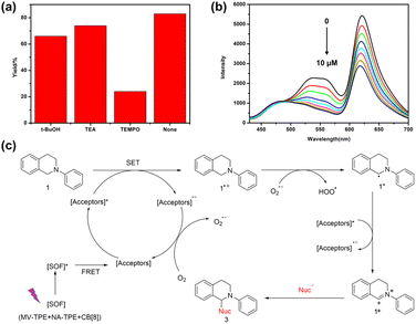
Moreover, to study the mechanism of the photocatalytic reaction, we also studied the active species in the catalytic CDC reaction catalyzed by the SOF + DBT + SR101 system. Three free radical scavengers tertiary butanol (t-BuOH), triethylamine (TEA), and (2,2,6,6-tetramethylpiperidin-1-yl)oxidanyl (TEMPO) were added to the reaction system to scavenge the hole (h+), hydroxyl radical (˙OH) and the superoxide anion radicals (O2˙−), respectively. As shown in Fig. 4a, after the addition of TEMPO, the yield of the CDC reaction showed a significant decrease (22%). However, the yield of the reaction remained almost the same with the participation of t-BuOH and TEA, which indicates that O2˙− is the main reactive species in the CDC reaction. In addition, the fluorescence titration experiments were also carried out to investigate the reaction mechanism. As shown in Fig. 4b, with the addition of N-phenyl tetrahydroisoquinoline to the solution of SOF + DBT + SR101 system, the emission peak of DBT and SR101 has significantly decreased, which demonstrates the electron transfer process between N-phenyl tetrahydroisoquinoline and DBT + SR101.
Based on the previous reports and the above experimental results,39,42,43 we propose a possible mechanism for the CDC reaction catalyzed by the SOF + DBT + SR101 system in an aqueous solution (Fig. 4c). First, the SOF reached its excited state under the irradiation of a UV lamp. Then, the energy was transferred from the [SOF]* to the acceptors (DBT and SR101) through the energy transfer process and [Acceptors]* was generated. Subsequently, 1 will lose one electron to generate 1˙+, and [Acceptors]* will abstract one electron to generate [Acceptors]˙−. This electron transfer process can be proved by the titration experiments of N-phenyl tetrahydroisoquinoline into the solution of SOF + DBT + SR101 (Fig. 4b). Then [Acceptors]˙− was quenched by O2 to generate O2˙− and [Acceptors] will regenerate. Subsequently, O2˙− will abstract one proton from 1˙+ to generate the intermediate 1˙. The [Acceptors]* will abstract one electron from 1˙ to generate [Acceptors]˙− and intermediate iminium 1+, and product 3 will be obtained after the addition of nucleophiles.
Conclusions
In summary, we successfully fabricated a three-component SOF based on the encapsulation-enhanced donor–acceptor interaction between MV-TPE, NA-TPE, and CB[8]. The obtained SOF exhibited strong emissions and further served as energy donors to fabricate artificial LHSs. An efficient two-step sequential energy transfer process from the SOF to DBT and then to SR101 can be realized by introducing DBT and SR101 into the solution of SOF. And the white light emission can be achieved by the direct addition of SR101 into the solution of SOF. In addition, to make full use of the harvested energy, we applied the SOF + DBT + SR101 system as a catalyst to promote the CDC reaction in water. The LHS herein exhibits excellent catalytic ability in the CDC reaction and can be applied to a wide range of substrates. This work realizes for the first time the fabrication of an artificial LHS based on a SOF and further applies it to photocatalytic reactions, which provides a new strategy for constructing artificial LHSs for photocatalysis.Author contributions
Ying Wang: investigation, methodology, data curation, writing – original draft. Chao-Qun Ma: methodology, data curation. Xin-Long Li: methodology, data curation. Rui-Zhi Dong: methodology. Hui Liu: methodology, funding acquisition, resources. Rong-Zhou Wang: funding acquisition, resources. Shengsheng Yu: methodology, funding acquisition, resources. Ling-Bao Xing: conceptualisation, funding acquisition, project administration, resources, supervision, writing – review & editing.Conflicts of interest
There are no conflicts to declare.Acknowledgements
The authors acknowledge the support from the National Natural Science Foundation of China (52205210 and 22005179) and the Natural Science Foundation of Shandong Province (ZR2020MB018, ZR2022QE033, ZR2021QB049, and ZR2020QB113).References
- K. D. Zhang, J. Tian, D. Hanifi, Y. Zhang, A. C. Sue, T. Y. Zhou, L. Zhang, X. Zhao, Y. Liu and Z. T. Li, J. Am. Chem. Soc., 2013, 135, 17913–17918 CrossRef CAS PubMed
.
- J. Tian, T. Y. Zhou, S. C. Zhang, S. Aloni, M. V. Altoe, S. H. Xie, H. Wang, D. W. Zhang, X. Zhao, Y. Liu and Z. T. Li, Nat. Commun., 2014, 5, 5574 CrossRef CAS PubMed
.
- B. Yang, S. B. Yu, P. Q. Zhang, Z. K. Wang, Q. Y. Qi, X. Q. Wang, X. H. Xu, H. B. Yang, Z. Q. Wu, Y. Liu, D. Ma and Z. T. Li, Angew. Chem., Int. Ed., 2021, 60, 26268–26275 CrossRef CAS PubMed
.
- Y. Li, Q. Li, X. Miao, C. Qin, D. Chu and L. Cao, Angew. Chem., Int. Ed., 2021, 60, 6744–6751 CrossRef CAS PubMed
.
- Y. P. Wu, B. Yang, J. Tian, S. B. Yu, H. Wang, D. W. Zhang, Y. Liu and Z. T. Li, Chem. Commun., 2017, 53, 13367–13370 RSC
.
- X. H. Wang, N. Song, W. Hou, C. Y. Wang, Y. Wang, J. Tang and Y. W. Yang, Adv. Mater., 2019, 31, 1903962 CrossRef PubMed
.
- Y. Sun, F. Guo, T. Zuo, J. Hua and G. Diao, Nat. Commun., 2016, 7, 1–13 Search PubMed
.
- H. Wu, Y. Chen, X. Dai, P. Li, J. F. Stoddart and Y. Liu, J. Am. Chem. Soc., 2019, 141, 6583–6591 CrossRef CAS PubMed
.
- W. C. Geng, Y. C. Liu, Y. Y. Wang, Z. Xu, Z. Zheng, C. B. Yang and D. S. Guo, Chem. Commun., 2016, 53, 392–395 RSC
.
- H. Wu, Y. Chen, X. Dai, P. Li, J. F. Stoddart and Y. Liu, J. Am. Chem. Soc., 2019, 141, 6583–6591 CrossRef CAS PubMed
.
- H. Bai, Z. Liu, T. Zhang, J. Du, C. Zhou, W. He, J. H. C. Chau, R. T. K. Kwok, J. W. Y. Lam and B. Z. Tang, ACS Nano, 2020, 14, 7552–7563 CrossRef CAS PubMed
.
- Y. Liu, S. Li, K. Li, Y. Zheng, M. Zhang, C. Cai, C. Yu, Y. Zhou and D. Yan, Chem. Commun., 2016, 52, 9394–9397 RSC
.
- I. Shulov, S. Oncul, A. Reisch, Y. Arntz, M. Collot, Y. Mely and A. S. Klymchenko, Nanoscale, 2015, 7, 18198–18210 RSC
.
- P. Wei, X. Yan and F. Huang, Chem. Soc. Rev., 2015, 44, 815–832 RSC
.
- K. Acharyya, S. Bhattacharyya, H. Sepehrpour, S. Chakraborty, S. Lu, B. Shi, X. Li, P. S. Mukherjee and P. J. Stang, J. Am. Chem. Soc., 2019, 141, 14565–14569 CrossRef CAS PubMed
.
- P. P. Jia, L. Xu, Y. X. Hu, W. J. Li, X. Q. Wang, Q.
H. Ling, X. Shi, G. Q. Yin, X. Li, H. Sun, Y. Jiang and H. B. Yang, J. Am. Chem. Soc., 2021, 143, 399–408 CrossRef CAS PubMed
.
- H.-Q. Peng, C.-L. Sun, L.-Y. Niu, Y.-Z. Chen, L.-Z. Wu, C.-H. Tung and Q.-Z. Yang, Adv. Funct. Mater., 2016, 26, 5483–5489 CrossRef CAS
.
- H. Q. Peng, J. F. Xu, Y. Z. Chen, L. Z. Wu, C. H. Tung and Q. Z. Yang, Chem. Commun., 2014, 50, 1334–1337 RSC
.
- H. Liu, Z. Zhang, Y. Zhao, Y. Zhou, B. Xue, Y. Han, Y. Wang, X. Mu, S. Zang, X. Zhou and Z. Li, J. Mater. Chem. B, 2019, 7, 1435–1441 RSC
.
- J. Li, Y. Zhao, Y. Dong, Y. Yu, L. Cao and B. Wu, CrystEngComm, 2016, 18, 7929–7933 RSC
.
- H. Liu, Q. Pan, C. Wu, J. Sun, T. Zhuang, T. Liang, X. Mu, X. Zhou, Z. Li and Y. Zhao, Mater. Chem. Front., 2019, 3, 1532–1537 RSC
.
- L. Zhang, T.-Y. Zhou, J. Tian, H. Wang, D.-W. Zhang, X. Zhao, Y. Liu and Z.-T. Li, Polym. Chem., 2014, 5, 4715–4721 RSC
.
- Y. Li, C. Qin, Q. Li, P. Wang, X. Miao, H. Jin, W. Ao and L. Cao, Adv. Opt. Mater., 2020, 8, 1902154 CrossRef CAS
.
- Y. Li, Y. Dong, X. Miao, Y. Ren, B. Zhang, P. Wang, Y. Yu, B. Li, L. Isaacs and L. Cao, Angew. Chem., Int. Ed., 2018, 57, 729–733 CrossRef CAS PubMed
.
- J. H. H. J. Kim, W. S. Jeon, E. Lee, J. Kim, S. Sakamoto and K. Kim, Angew. Chem., Int. Ed., 2001, 40, 1526–1529 CrossRef PubMed
.
- M. Pfeffermann, R. Dong, R. Graf, W. Zajaczkowski, T. Gorelik, W. Pisula, A. Narita, K. Mullen and X. Feng, J. Am. Chem. Soc., 2015, 137, 14525–14532 CrossRef CAS PubMed
.
- L. Zhang, Y. Jia, H. Wang, D.-W. Zhang, Q. Zhang, Y. Liu and Z.-T. Li, Polym. Chem., 2016, 7, 1861–1865 RSC
.
- X. Zhang, G. Ren, Z. He, W. Yang, H. Li, Y. Wang, Q. Pan and X. Shi, Cryst. Growth Des., 2020, 20, 6888–6895 CrossRef CAS
.
- Y. Zhang, T. G. Zhan, T. Y. Zhou, Q. Y. Qi, X. N. Xu and X. Zhao, Chem. Commun., 2016, 52, 7588–7591 RSC
.
- J. Liu, Y.-Q. Fan, S.-S. Song, G.-F. Gong, J. Wang, X.-W. Guan, H. Yao, Y.-M. Zhang, T.-B. Wei and Q. Lin, ACS Sustainable Chem. Eng., 2019, 7, 11999–12007 CAS
.
- H. J. Lee, H. J. Kim, E. C. Lee, J. Kim and S. Y. Park, Chem.–Asian J., 2018, 13, 390–394 CrossRef CAS PubMed
.
- J. Tian, Z. Y. Xu, D. W. Zhang, H. Wang, S. H. Xie, D. W. Xu, Y. H. Ren, H. Wang, Y. Liu and Z. T. Li, Nat. Commun., 2016, 7, 11580 CrossRef CAS PubMed
.
- Y. C. Zhang, P. Y. Zeng, Z. Q. Ma, Z. Y. Xu, Z. K. Wang, B. Guo, F. Yang and Z. T. Li, Drug Delivery, 2022, 29, 1–9 CrossRef CAS PubMed
.
- Z. Y. Xu, W. Mao, Z. Zhao, Z. K. Wang, Y. Y. Liu, Y. Wu, H. Wang, D. W. Zhang, Z. T. Li and D. Ma, J. Mater. Chem. B, 2022, 10, 899–908 RSC
.
- W. Wang, B. Qi, X. Yu, W. Z. Li, Z. Yang, H. Zhang, S. Liu, Y. Liu and X. Q. Wang, Adv. Funct. Mater., 2020, 30, 2004452 CrossRef CAS
.
- J. J. Li, Y. Chen, J. Yu, N. Cheng and Y. Liu, Adv. Mater., 2017, 29, 1701905 CrossRef PubMed
.
- D. Zhang, Y. Liu, Y. Fan, C. Yu, Y. Zheng, H. Jin, L. Fu, Y. Zhou and D. Yan, Adv. Funct. Mater., 2016, 26, 7652–7661 CrossRef CAS
.
- Z. Zhang, Z. Zhao, Y. Hou, H. Wang, X. Li, G. He and M. Zhang, Angew. Chem., Int. Ed., 2019, 58, 8862–8866 CrossRef CAS PubMed
.
- W.-J. Li, X.-Q. Wang, D.-Y. Zhang, Y.-X. Hu, W.-T. Xu, L. Xu, W. Wang and H.-B. Yang, Angew. Chem., Int. Ed., 2021, 60, 18761–18768 CrossRef CAS PubMed
.
- C.-Q. Ma, X.-L. Li, N. Han, Y. Wang, R.-Z. Wang, S. Yu, Y.-B. Wang and L.-B. Xing, J. Mater. Chem. A, 2022, 10, 16390–16395 RSC
.
- M. Hao, G. Sun, M. Zuo, Z. Xu, Y. Chen, X. Y. Hu and L. Wang, Angew. Chem., Int. Ed., 2020, 59, 10095–10100 CrossRef CAS PubMed
.
- C. J. Wu, J. J. Zhong, Q. Y. Meng, T. Lei, X. W. Gao, C. H. Tung and L. Z. Wu, Org. Lett., 2015, 17, 884–887 CrossRef CAS PubMed
.
- J.-J. Zhong, Q.-Y. Meng, G.-X. Wang, Q. Liu, B. Chen, K. Feng, C.-H. Tung and L.-Z. Wu, Chem.–Eur. J., 2013, 19, 6443–6450 CrossRef CAS PubMed
.
Footnote |
| † Electronic supplementary information (ESI) available. See DOI: https://doi.org/10.1039/d2ta09227a |
| This journal is © The Royal Society of Chemistry 2023 |

