DOI:
10.1039/D2SM01675C
(Paper)
Soft Matter, 2023,
19, 2319-2329
Torsion-induced stick-slip phenomena in the delamination of soft adhesives†
Received
20th December 2022
, Accepted 27th February 2023
First published on 28th February 2023
Abstract
Soft adhesive contacts are ubiquitous in nature and are increasingly used in synthetic systems, such as flexible electronics and soft robots, due to their advantages over traditional joining techniques. While methods to study the failure of adhesives typically apply tensile loads to the adhesive joint, less is known about the performance of soft adhesives under shear and torsion, which may become important in engineering applications. A major challenge that has hindered the characterization of shear/torsion-induced delamination is imposed by the fact that, even after delamination, contact with the substrate is maintained, thus allowing for frictional sliding and re-adhesion. In this work, we address this gap by studying the controlled delamination of soft cylinders under combined compression and torsion. Our experimental observations expose the nucleation of delamination at an imperfection and its propagation along the circumference of the cylinder. The observed sequence of ‘stick-slip’ events and the sensitivity of the delamination process to material parameters are explained by a theoretical model that captures axisymmetric delamination patterns, along with the subsequent frictional sliding and re-adhesion. By opening up an avenue for improved characterization of adhesive failure, our experimental approach and theoretical framework can guide the design of adhesives in future applications.
The advantages of adhesives, in comparison with traditional joining techniques, have fueled their development in various industries, with emerging applications in automotives,1 aerospace,2–4 structural engineering5–9 medical practice,10 and robotics.11 In contrast to mechanical fastening and welding, adhesives allow for the joining of dissimilar materials, have improved fatigue performance, and can reduce stress concentrations.12–14 Such improvements are traditionally estimated via testing in specific plane-strain geometric settings, such as ‘lap-joint’ tests12–14 and peeling tests,12,15–17 or in axially symmetric settings, such as ‘probe tack tests’ using either flat or spherical punches.18 However, these results cannot be directly translated to explain and predict the performance of adhesive joints in more complex loading conditions.
We can classify the failure of adhesives into two broad categories:19 (i) failure in the bulk of the adhesive, and (ii) failure at the interface between the adhesive layer and the materials that it is bonding, also known as peeling or delamination. While several studies have been devoted to enhancing the durability of adhesives and preventing delamination by tuning the material composition,12,20–22 the loading state and geometry of the system can also affect the strength and failure mode of the adhesive joint.23 For example, peeling tests are commonly conducted by pulling the adhesive off the substrate at an angle, and the force at which delamination occurs has been shown to depend on the loading angle.16 Additionally, recent work on longitudinally-loaded rectangular adhesive pads15,17 discovered a tradeoff between two failure modes (cavitation and curling) that depends on the dimensions of the adhesive and its ability to re-establish the bond upon contact with the substrate after initial peeling.
One phenomenon that has garnered particular interest is the delamination of adhesive joints subjected to torsional loading. Several researchers have conducted torsion-delamination tests with rigid spherical indenters in contact with a planar adhesive sample,24,25 while others have studied tubular joints where the adhesive layer is sandwiched between two coaxial cylindrical shells.19,26,27 However, rather than examining the progression of delamination in detail, these analyses are geared towards quantifying the interfacial toughness and thus focus on a limited set of observations (i.e. the initiation of delamination). Accordingly, such experiments are configured to minimize the influence of transient interfacial phenomena. Spherical adhesive joints are used to produce localized deformations at a small point of contact between the indenter and the substrate. Similarly, tubular joints (in which adhesives bond the lateral surfaces of two coaxial cylinders) minimize the thickness of the adhesive zone and often are not conducive to visual observation, especially for joints with adherends made of an opaque material like steel.26 Hence, alternative methods are needed to obtain measurements that may explain and predict delamination in realistic settings, where the adhesive bond does not ‘fail’ instantaneously, but rather undergoes a complex delamination process that is highly dependent on the interfacial geometry and the presence of imperfections.
Our study relies on a different geometry: a cylindrical adhesive sample with one circular face in contact with a glass substrate. We apply axial compression to adhere the sample to the glass, then we apply torsion and observe the initiation and progression of delamination. Consistent with prior work, we have chosen to use the naturally-adhesive elastomer polydimethylsiloxane (PDMS) as our laboratory model of an adhesive material, and we have used glass as the substrate.24,28 This configuration has multiple advantages over the ones mentioned above. It provides a better model of the real-world applications of adhesives compared to the spherical indenter tests, since adhesives under torsion (e.g. composite laminates) are more likely to have adhesive contact in a planar setting than on a sphere. In addition, the use of a transparent adhesive and substrate in contact on the cylinder's circular surface (instead of the lateral surface) allows for visual tracking of the delamination process in a way that the tubular joint tests do not. This setup therefore enables us to observe behaviors beyond the initiation of delamination and to capture the effect of nonlinear deformations, which have recently been shown to play a significant role in determining the interfacial toughness of soft adhesives.29,30
Some preliminary research has already been conducted on the cylinder/flat-plate geometry we propose. The linear elastic model created by Pérez-Ràfols and Nicola31 considers the initiation of delamination, but did not capture the reattachment and stick-slip behavior. Chaudhury and Chung28 studied the same configuration through an experimental lens; they placed a glass disk in torsional contact with a thin PDMS film and observed the formation of delamination cavities and stick-slip behavior consistent with prior observations of Schallamach waves on adhesive joints.32,33 To minimize effects of bulk deformation, Chaudhury and Chung28 focused on thin films. However, in some adhesive applications (such as robotic grippers), the adhesive's thickness may be on the same order of magnitude as its radius, so it is necessary to observe the deformation of thick adhesive layers under torsion as well. Our work aims to address the limitations of these prior studies, in order to develop a comprehensive understanding of the initiation and progression of delamination in cylindrical adhesive joints. Our experimental configuration also enables the investigation of stick-slip cycles and the propagation of Schallamach waves,33 where the adhesive-substrate interface ruptures and then re-establishes the bond.17
This manuscript is organized as follows: In the next section, we detail our experimental procedure and discuss the experimental findings. These observations agree with the key results of a minimal theory, presented in Section 2, which captures both the delamination, frictional sliding, and stick-slip cycles of cylindrical adhesives under combined compression and torsion. We show results of the model in Section 3 and conclude in Section 4.
1 Experimental observations
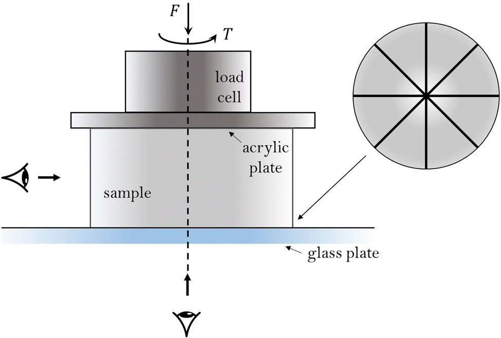
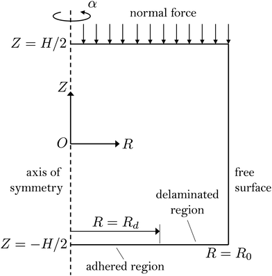
To examine the delamination patterns that emerge under a combination of compressive and torsional loading, we developed a cylindrical experimental model (Fig. 1). We fabricated cylindrical samples of PDMS34,35 (Sylgard 184) with diameter 2.4 cm, height 1 cm, and a base:cross-linker ratio of 40![[thin space (1/6-em)]](https://www.rsc.org/images/entities/char_2009.gif) :1 to yield an elastic modulus E ∼ 21 kPa, as measured from the torsion data in the linear range. We chose to limit our analysis to these small samples due to the high sensitivity of wider samples to imperfections in the tilt of the experimental setup (as discussed in the ESI†). We placed one circular surface of each sample in weakly-bonded adhesive contact with a glass plate (see ESI† for fabrication procedure). The other cylindrical surface was rigidly bonded to an acrylic disk using cyanoacrylate glue. Each acrylic disk was given a 3-digit Serial Number (SN) to aid in data processing.
:1 to yield an elastic modulus E ∼ 21 kPa, as measured from the torsion data in the linear range. We chose to limit our analysis to these small samples due to the high sensitivity of wider samples to imperfections in the tilt of the experimental setup (as discussed in the ESI†). We placed one circular surface of each sample in weakly-bonded adhesive contact with a glass plate (see ESI† for fabrication procedure). The other cylindrical surface was rigidly bonded to an acrylic disk using cyanoacrylate glue. Each acrylic disk was given a 3-digit Serial Number (SN) to aid in data processing.
 |
| | Fig. 1 Schematic illustration of the experimental configuration. The top surface of the PDMS sample is rigidly attached to an acrylic plate that can be rotated in the plane or vertically translated, as controlled by an Instron universal testing machine. The normal force and the torque are measured by the load cell. The bottom surface of the sample is marked with radial lines (which allow for tracking of the delamination process) and put in weak adhesive contact with a glass plate. The sample is viewed both from the side and from below. | |
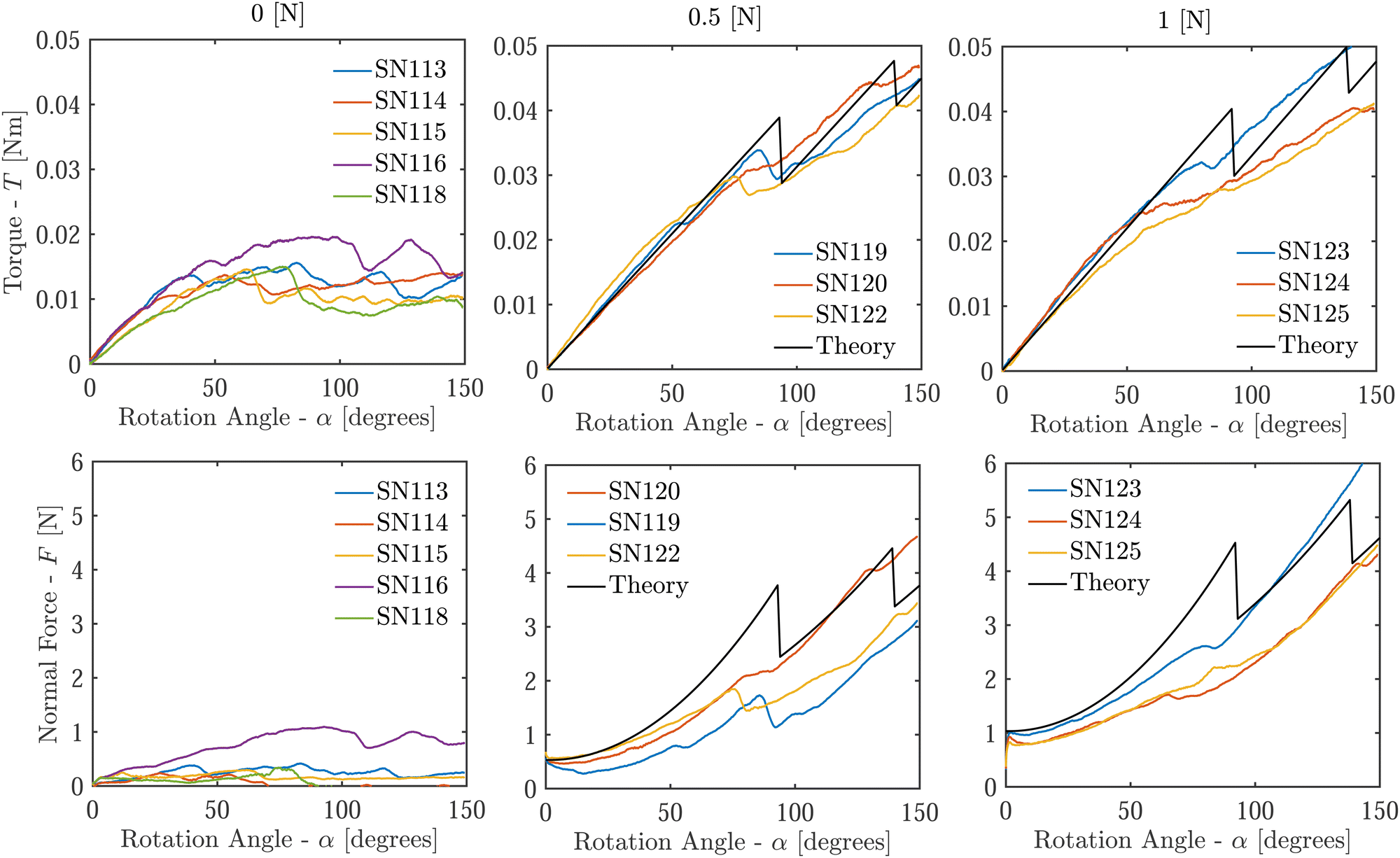
We attached the acrylic disk to the load cell of a dynamic Instron ElectroPuls E3000 universal testing machine and performed a combined compression-torsion test on the samples (details are given in ESI†). To characterize the effect of compressive normal force on the torsional delamination process, we initially applied one of three compressive force values F = (0,0.5,1) N, then rotated the load cell at a quasi-static rate of ![[small alpha, Greek, dot above]](https://www.rsc.org/images/entities/i_char_e14c.gif) = 0.2 deg s−1, up to the final rotation angle α = 150 degrees, while holding the load cell's vertical position constant. During the rotation, we measured the variation in torque (T) and normal force (F).
= 0.2 deg s−1, up to the final rotation angle α = 150 degrees, while holding the load cell's vertical position constant. During the rotation, we measured the variation in torque (T) and normal force (F).
We tracked the displacement of the sample at the interface with the glass plate by marking 4 straight lines at equal angular spacing across the diameter of the PDMS surface (Fig. 1). During each test, we took photographs of the the bottom surface (Fig. 2) and the lateral surface. From the images, we obtained a surface-averaged estimate of the radial fraction that had delaminated as a function of rotation angle (also shown in Fig. 2). Note that only the initial delamination of a given part of a radial line was considered – segments of the lines that had previously delaminated and re-adhered were still denoted as having delaminated. Corresponding measurements of the torque and normal force are shown in Fig. 3 (where compressive normal force values are positive). We used the images of the lateral surface to identify wrinkling instabilities and fracture initiation throughout the rotation, and after each test, we further examined the samples to determine the degree to which fractures had formed (see ESI†). We identified and eliminated clear outlier tests based on these results (more detail in ESI†).
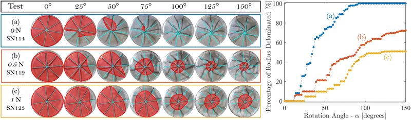 |
| | Fig. 2 Typical progression of delamination. On the left, the sequence of images shows delamination at different rotation angles for one representative sample in each of the three categories of applied normal force. The red-shaded region indicates the area that has not yet delaminated. The radial and circumferential progression of delamination is apparent, as is the change in the final delaminated state with increasing applied compression. On the right, the corresponding evolution of the surface-averaged delaminated radius is shown. The boxes around the sets of images (on the left) correspond to the colors of the curves (on the right). Time-lapse slideshows of the delamination process for these three tests can be found in the ESI.† | |
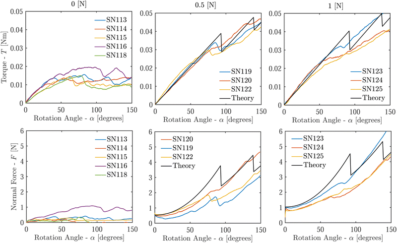 |
| | Fig. 3 Torque (top) and normal force (bottom), shown as a function of the rotation angle for the three initial values of normal force (columns). The variability between samples is caused by the imperfection sensitivity of the delamination process, and is most significant for samples with no initially-applied normal force. Correspondence between jumps in torque and jumps in normal force is also observed, and is associated with rapid delamination events (see ESI†). The outlier tests (SN117, SN121, and SN126) are not shown on the graphs (see ESI†). Black curves are results of the theoretical model using material parameters μ = 7 kPa, k = 0.5, and Γ = 53 J m−2, which corresponds to γ = 0.625. | |
Three sequential delamination phenomena emerge from our observations: (i) first, peeling initiates at a site of imperfect adhesion between the sample and glass; (ii) next, the delamination forms a front that propagates along the circumference and radially inward in a stick-slip manner; (iii) finally, the radial progression of delamination is arrested when fractures begin to form on the lateral surface, leaving an adhered region in the center of the interface. These trends are found to be consistent in samples that are subjected to normal force; in absence of a normal force, delamination occurs more abruptly over the entire surface. These behaviors are discussed below in more detail:
(i) Initiation
Across all the tests, peeling begins along the outer edge of the circular adhered surface at a site of imperfect adhesion between the sample and the glass plate, evident from the symmetry breaking in Fig. 2. This pattern is in accordance with analytical models of the delamination of tubular adhesive joints,27 in which imperfections on the outer edge of the joint lead to higher stresses and increased likelihood of shear failure. Interestingly, our experiments show that the level of defect sensitivity in the initiation and propagation of delamination can be tuned by applying a normal force, as seen by the increasing repeatability among tests with increasing normal force in Fig. 3.
(ii) Propagation
Once delamination initiates, it propagates circumferentially, as seen by the shrinkage of the red-shaded regions in Fig. 2 with increasing rotation angle. The propagation occurs in a stick-slip manner, such that regions that have previously delaminated re-adhere and later delaminate again. For samples with no applied normal force, delamination propagates through the sample's entire radius from the onset of peeling (Fig. 2a). For samples with an applied normal force, the stick-slip cycles start at the edge and spiral inward as they move around the circumference (Fig. 2b and c). The propagation of delamination that we observe is in line with results from prior torsion studies: the inward-radial progression matches the findings of Chateauminois et al.,24 and the circumferential stick-slip cycles are broadly consistent with the work of Chaudhury and Chung.28 This stick-slip process is visible as alternating jumps and plateaus in the delaminated radius percentage in Fig. 2 and corresponds to fluctuations in the otherwise-monotonic normal force and torque graphs (Fig. 3; also see ESI† for more detail).
(iii) Arrest
In all samples, we eventually observe the termination of delamination. The reason for the termination depends on the applied normal force. For samples with non-zero applied force, the delamination stops at some radial distance from the center, giving way to fracturing. For samples without applied compression, the entire sample delaminates by the end of the test and does not fracture. This behavior may be seen by contrasting the observations in Fig. 2: in the absence of normal force, the sample fully delaminates by 92 degrees of rotation, while the plots for samples with an initial normal force reach a plateau prior to delaminating through the whole surface.
Aside from the three observations detailed above, we identified experimental evidence of several other phenomena. In Fig. 3, the normal compression is shown to increase as the rotation angle increases. This finding is consistent with the well-documented ‘Poynting effect’,36 which predicts that torsion elongates cylinders, so compression must be applied to preserve their height.37,38 At the very beginning of rotation, the normal force sometimes decreases before it begins to increase – one possible explanation is that any initial misalignment can cause the cylinder to reconfigure at onset of loading. This effect induces an offset of the normal force throughout the loading, which becomes more pronounced for larger samples, as shown in the ESI.† In addition, we observed the emergence of wrinkles on the lateral surface of the cylinders once the sample was rotated beyond a critical angle, in accordance with the theory proposed by Ciarletta and Destrade.39 While the fractures on the lateral surface have been discussed briefly above, more investigation is required to understand the particular fracturing patterns that emerge in these compression/torsion tests. More detail on the wrinkling and fracturing patterns we observed is provided in the ESI.†
Based on the experimental data, delamination of a circular surface under combined axial compression and torsion is a process in which an initial imperfection in the adhesion between the PDMS sample and the glass plate creates a delamination front that propagates circumferentially and radially inward. The sample often re-adheres to the substrate after delamination, creating successive stick-slip waves. Fluctuations in the trends of normal force and torque as a function of the rotation angle correspond to snap-through events where delamination progresses rapidly. The delamination process is highly sensitive to imperfections, though application of a normal force is shown to reduce the level of imperfection sensitivity and make the process considerably more repeatable. Moreover, by resisting delamination, applied compression limits the radial range of delamination and eventually drives the sample to fracture rather than delaminate the innermost part of the surface. However, if no normal force is initially applied, the sample delaminates across the whole interface and does not fracture. The physical mechanisms behind these key observations are discussed through a theoretical lens below.
2. Theoretical framework
In this section, we derive a theoretical model that can explain the experimental phenomena described in the previous section. A key assumption that we make, to simplify the kinematic description, is axial symmetry. Although our experimental observations exhibit delamination patterns that start locally at imperfections, and are thus not initially axially symmetric, we find that, with applied normal force, the delamination propagates circumferentially and stabilizes once it completes a whole circle. Hence, axial symmetry becomes a good approximation to capture the quasistatic process, allowing us to obtain insights on the observed phenomena.
Problem setting and kinematic assumptions
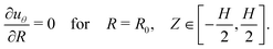
To describe the experimental system illustrated in Fig. 1, we consider an elastic cylinder made of a hyperelastic, isotropic, homogeneous, and incompressible material. Its undeformed axial length is denoted by H, and it has an undeformed radius of R0. Material points are labeled using the cylindrical coordinate system, as X = X(R, Θ, Z) in the undeformed state, such that| | | 0 ≤ R ≤ R0, 0 ≤ Θ < 2π, −H/2 ≤ Z ≤ H/2, | (1) |
as illustrated in Fig. 4. Upon deformation, a mapping function x = χ(X) assigns the material points to their location in the deformed cylindrical coordinates x = x(r, θ, z).
 |
| | Fig. 4 Illustration of the boundary value problem. | |
The cylinder is initially pushed against a rigid substrate (at Z = −H/2), by application of a normal stress at the top surface (Z = H/2), which is then rotated quasistatically to increase the prescribed rotation angle α. Delamination is permitted only at the bottom surface and, with the assumption of axial symmetry, is restricted to the annular region Rd ≤ R ≤ R0, where the innermost radius of the delaminated region, Rd = Rd(α), can vary throughout the loading. Understanding the propagation of this delamination front and its dependence on model parameters is the central goal of this formulation.
To simplify the mathematical derivation, a set of kinematic assumptions are made. First, we assume that horizontal planes remain horizontal throughout the deformation. Second, we impose axial symmetry such that the deformation field is independent of Θ. As a result of these two assumptions, the vertical displacement uz of any point on a horizontal plane is independent of the radial and angular coordinates (i.e. uz = uz(Z)). We restrict our attention to small initial vertical deformations imposed by the applied normal force, which results in a uniform vertical stretch (λz = ∂z/∂Z) that is held constant throughout the torsion process. Lastly, we assume that the cylinder preserves its cylindrical shape throughout the deformation process, namely that radial displacements are independent of the vertical coordinate, i.e. the radial displacement function becomes ur = ur(R). This assumption neglects any barreling effects that may occur in the initial compression, essentially implying that the initial compression permits sliding along the substrate. Additionally, wrinkling of the free surface of the cylinder is neglected. In our experiments, such wrinkling may emerge at large rotations, as described in the previous section, but capturing the wrinkling process is beyond the scope of this theory. With these kinematic assumptions, we are left with displacement fields of the form
| | | r = R + ur(R), θ = Θ + uθ(R, Z), z = Z + uz(Z), | (2) |
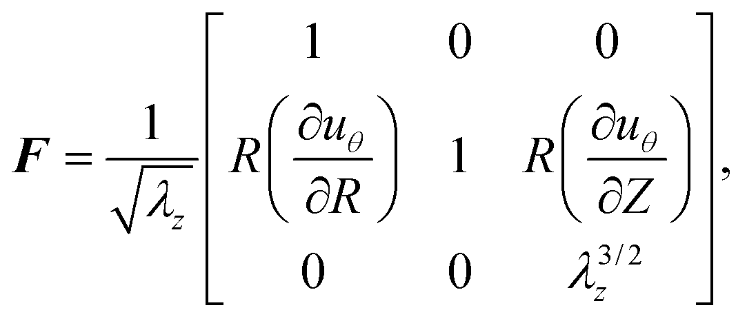
where the displacement functions are defined as the difference between the deformed (lowercase) and undeformed (uppercase) coordinates. The deformation gradient
F = ∂
χ/∂
X can thus be written as
| | 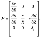 | (3) |
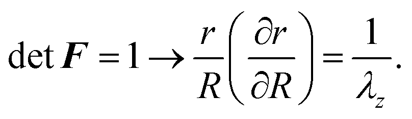
and incompressibility implies
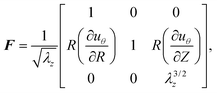
| | 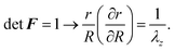 | (4) |
Integrating the above formula, and eliminating radial translation of the cylinder (
i.e. imposing
ur(0) = 0), yields the relations
| | 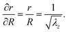 | (5) |
Substituting the above result into
(3), we obtain the final form of the deformation gradient as
| |  | (6) |
where the only remaining unknown field variable is the angular displacement function
uθ.
Governing equations and boundary conditions
The problem at hand is concerned with a non-conservative process, whereby torsional deformation induces delamination and frictional sliding. All of these energetic contributions must be considered to determine the propagation of delamination Rd(α). Nonetheless, if Rd and α are separately prescribed, the deformation of the elastic body, uθ(R, Z; Rd, α) and the corresponding stored elastic energy Ee = Ee(Rd, α), can be derived for a known set of boundary conditions (note the notation used in defining uθ: the variables before the semicolon are spatial coordinates, while those after the semicolon are prescribed system parameters). After obtaining Ee = Ee(Rd, α), we will also consider the surface energy Ed = Ed(Rd), i.e. the energy invested in delamination, and we will show in the next subsection that the work done by friction can be represented as an effective potential Ef = Ef(Rd). By combining all of these energetic contributions, we will determine the location of the delamination front as the one that minimizes the total energy in the system.
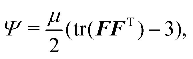
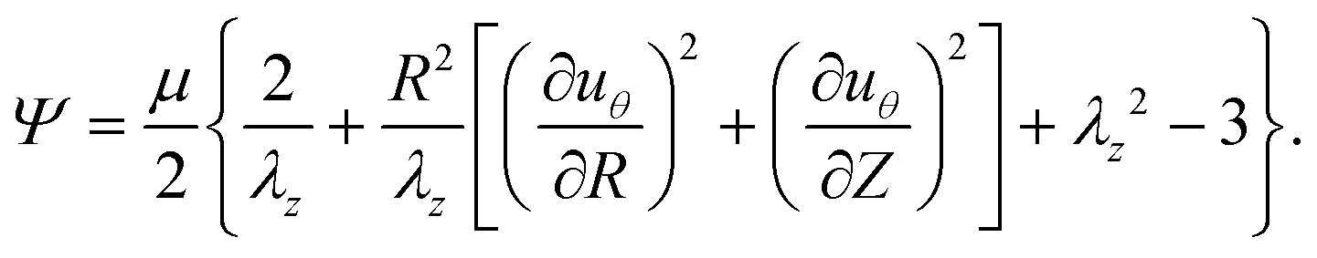
First, we employ the neo-Hookean model to describe the elastic strain energy density of the material as
| | 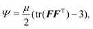 | (7) |
where
μ is the shear modulus. Substituting
(6) in
(7) gives
| |  | (8) |
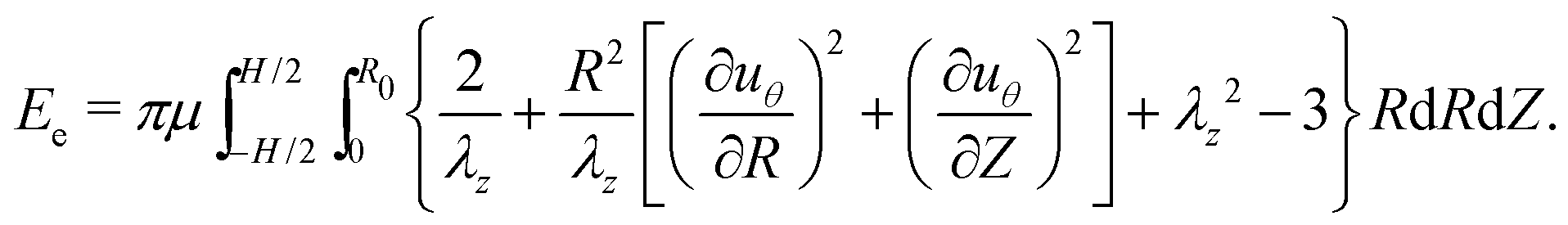
The total elastic energy of the system,
Ee, is thus given by integration of the strain energy density over the entire volume of the cylinder:
| | 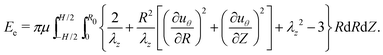 | (9) |
Next, the virtual work
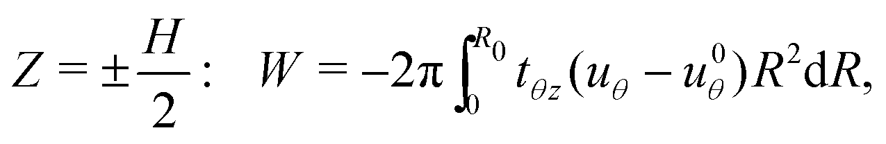
W done by the traction force on the top and bottom surfaces, can be written as
| | 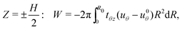 | (10) |
where
tθz is the generalized shear traction corresponding to displacement
uθ, but is defined positive in the opposite direction. Here, without loss of generality, we assume an arbitrary externally applied shear traction and account for pre-deformation of the adhered surface,
u0θ =
u0θ(
R). Though initially
u0θ = 0; if a ‘stick-slip’ event occurs, bonding of the interface can be re-established imposing a nonzero
u0θ(
R). This will be explained later in more detail in describing the boundary conditions and solution procedure.
An additional energy contribution Ed comes from the creation of new surface area as the bottom surface of the cylinder delaminates – this contribution can be written as
where
Γ is the interface toughness per unit area.
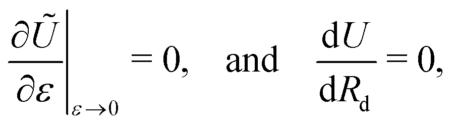
An equilibrium solution minimizes the potential energy U in the system,
For a prescribed rotation angle
α, the potential energy is a functional of
uθ and
Rd,
i.e. U =
U(
uθ,
Rd;
α).
Using the tools of calculus of variations, we consider perturbations of the stationary function uθ(R,Z) in the form ũθ = uθ + εδuθ, where δuθ(R, Z) is an arbitrary function that must vanish on the boundaries of the body that are subjected to a displacement constraint, and ε is a small constant. Next, we substitute ũθ into the potential energy and require that
| | 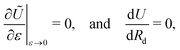 | (13) |
where we have used the notation
Ũ =
U(
ũθ,
Rd;
α). Additionally, a full derivative in the second equation accounts for the dependence of the displacement field on the location of the delamination front, which may emerge from the boundary condition at
Z = −
H/2, such that
uθ =
uθ(
R,
Z;
Rd).
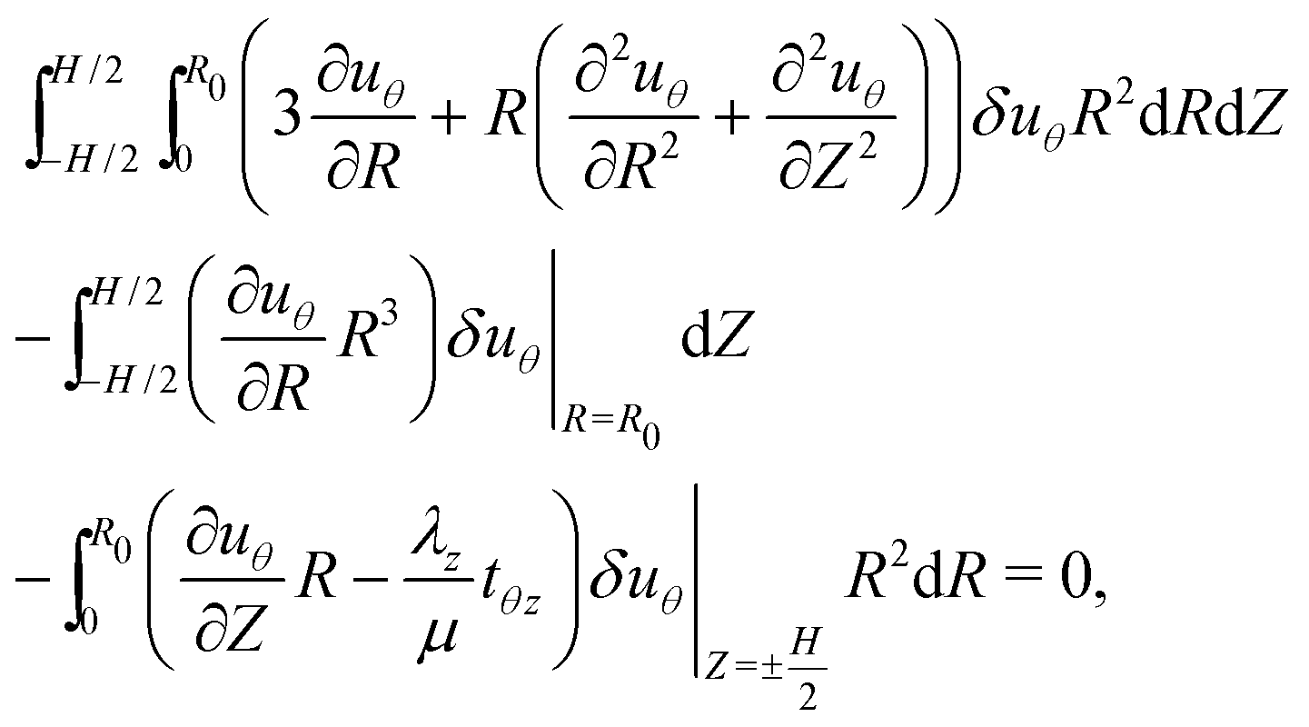
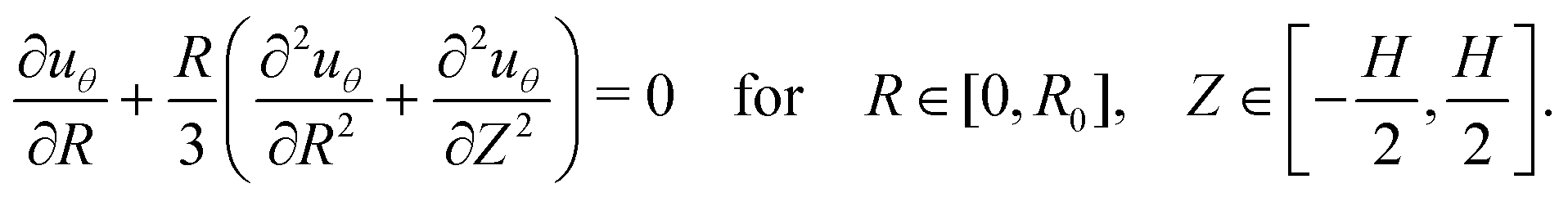
By substituting (9) and (10) and performing integration by parts, the first of the above two equations can be recast in the following form
| | 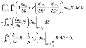 | (14) |
which does not depend on the interfacial energy contribution (
Ed). For the above equality to hold for an arbitrary variation
δuθ, each term must vanish separately. The first term gives rise to the governing equation
| | 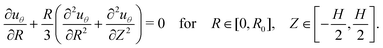 | (15) |
The second integral implies that on the free boundary of the cylinder, we have
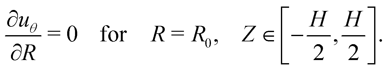
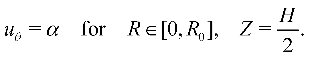
| |  | (16) |
The last integral corresponds to the top and bottom surfaces of the cylinder. At
Z =
H/2, to enforce uniform rotation about the axis of symmetry, the displacement is prescribed as
| |  | (17) |
Hence, the variation must vanish (
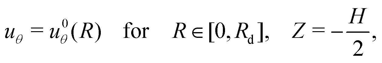
δuθ = 0), and thus the corresponding integral term vanishes. At
Z = −
H/2, we split the integral to distinguish the different regions of the surface. In the adhered region, the displacement is prescribed:
| |  | (18) |
and thus the corresponding integral term vanishes.
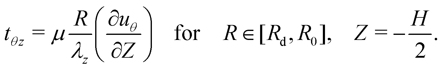
In the delaminated region, sliding is permitted and can be balanced by a shear traction. The variation need not vanish in this region and thus, to ensure that the integral term vanishes, we enforce
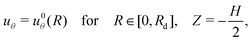
| |  | (19) |
The shear traction that emerges from the frictional sliding between the substrate and the cylinder acts as an external force on the system and needs to be prescribed to complete the boundary value problem.
Eshelby-like force as a driver of delamination
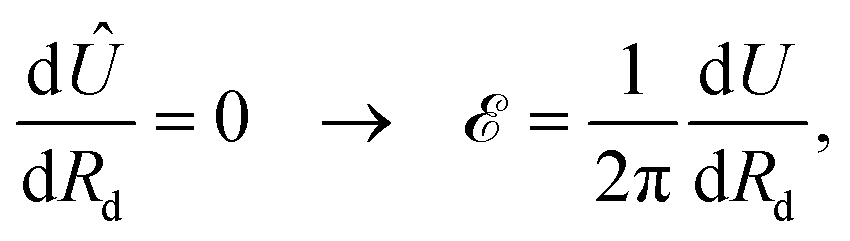
Inspired by the work of Bigoni et al.,40,41 we now perform the differentiation in (13)2, to obtain the configurational force associated with propagation of delamination. Such forces are often named after Eshelby.42,43
It is instructive to note that the derivative in (13)2 is directly related to the “energy release rate”, which is commonly considered in fracture mechanics. The resulting integral that we write next is thus a specialized version of the J-integral, for the present problem. An illuminating discussion on the analogies between these different formulations for a 1D delamination problem is found in ref. 44. Here, the derivation is complicated by the fact that we are considering a 2D field with combined traction and displacement boundary conditions, as detailed next.
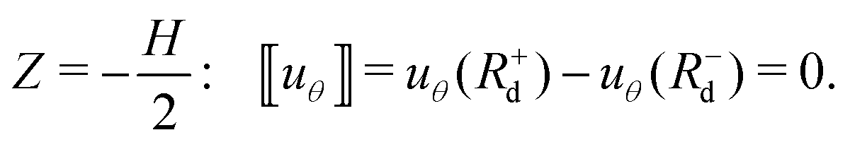
First, it is instructive to examine the differentiability of the displacement function, uθ(R, Z; Rd). In the bulk of the homogeneous cylinder, we can assume the displacement field is smooth, namely that uθ ∈ C2. However, the transition from a displacement boundary condition (18) to a traction boundary condition (19) permits discontinuity in the slope of uθ at (R, Z) = (Rd, −H/2), while continuity of uθ must be preserved, namely
| |  | (20) |
Here, we have introduced the bracket notation, which will be used in this work as a short-hand to denote the jump of a function exclusively at (
R,
Z) = (
Rd, −
H/2).
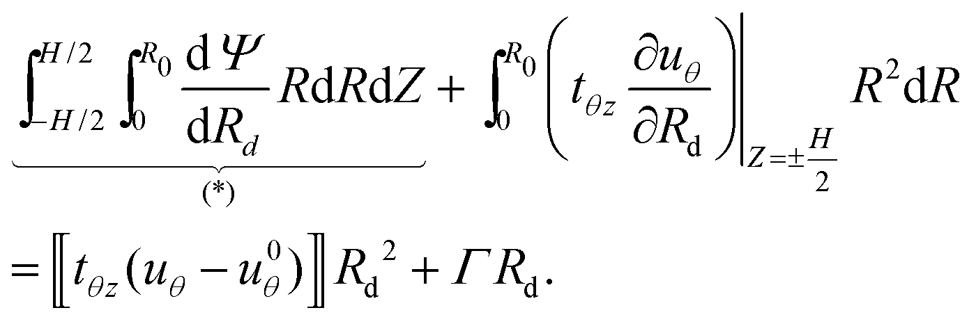
Accordingly, we perform the differentiation in (13)2 while using the Leibniz integral rule to account for the discontinuity at (R, Z) = (Rd, −H/2), to write‡
| |  | (21) |
Here, to simplify the derivation, we consider an arbitrary surface traction,
tθz, at
Z = ±
H/2 and permit a jump in its value at (
R,
Z) = (
Rd, −
H/2). The notation (*) is introduced to denote the first integral term that we evaluate next.
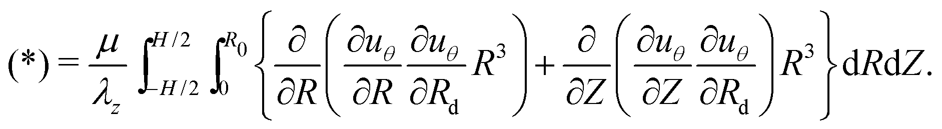
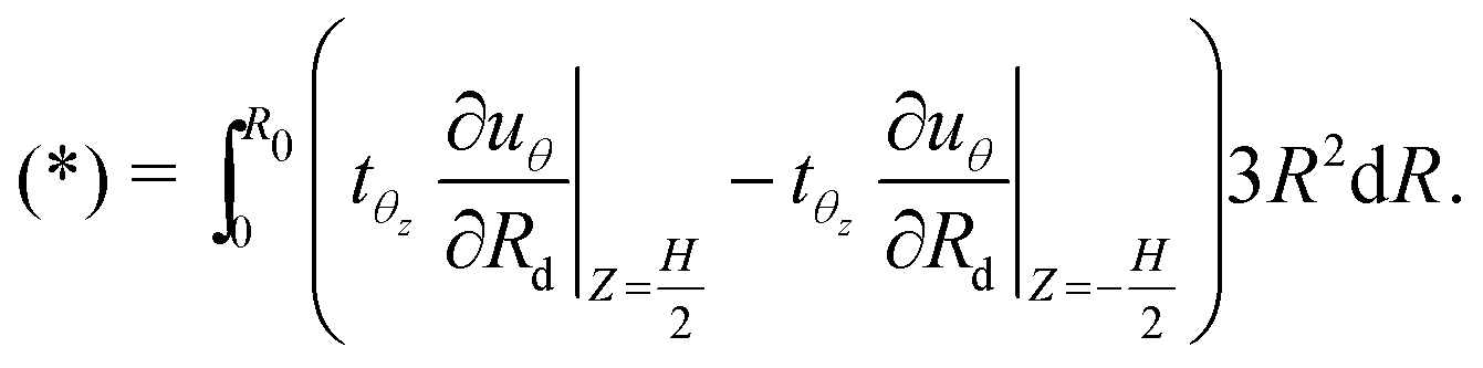
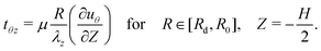
By substituting (8) in (*), performing integration by parts, and making use of the governing eqn (15), we have
| |  | (22) |
By direct integration of the above terms, and making use of the boundary condition
(16) and the relation for the boundary traction
(19), we find that the first integral cancels and the remaining term reads
| | 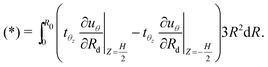 | (23) |
Now, by substituting
(23) in
(21) and noticing that according to
(17), ∂
uθ/∂
Rd = 0 at
Z =
H/2, the derivative in
(13)2 can be recast in the form
| |  | (24) |
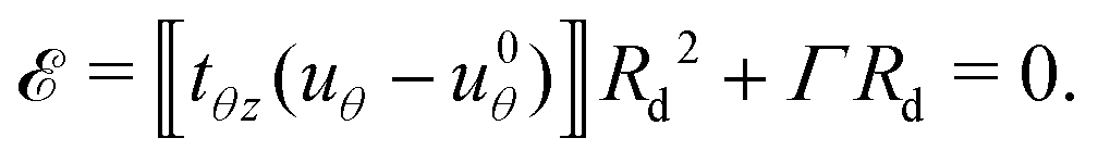
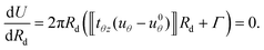
To determine the Eshelby-like force that emerges from this analysis, we use the principle of virtual work to write a modified potential energy in the form
| | Û = U − 2πRd![[scr E, script letter E]](https://www.rsc.org/images/entities/char_e140.gif) , , | (25) |
where
is an Eshelby-like force, and the second term on the right-hand-side represents the virtual work done by this configurational force in propagating the delamination front along the negative
R direction. In equilibrium we require
| |  | (26) |
and thus from
(24) we have
| |  | (27) |
As seen from the above result, the Eshelby-like force is determined from the singularity at the delamination front.
42 Namely, since
uθ −
u0θ → 0 as
R →
Rd the shear traction must become unbounded (
i.e. tθz → ∞). From a numerical point of view this becomes intractable and is thus avoided in this work by directly performing the differentiation in
(13)2, in analogy to the use of the J-integral.
45
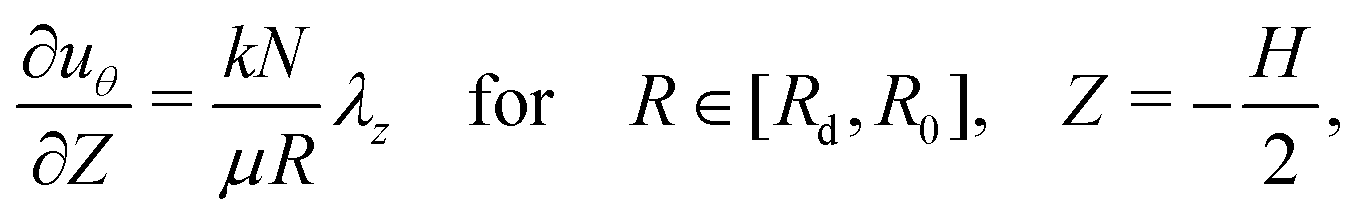
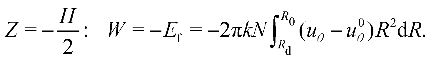
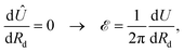
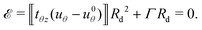
Work of friction as an effective potential
The above derivation considered an arbitrary applied shear traction, tθz, on the top and bottom boundaries of the cylinder (Z = ±H/2). Here we specialize the formulation to the specific boundary conditions. As a first step, we notice that the virtual work on the displacement controlled boundaries can be neglected. On the remaining boundary, at the limit of quasistatic motion, we can simplify the representation of the kinetic friction by assuming that it is constant throughout the sliding, and proportional to the initially applied normal force N through the constant k, such that tθz = kN. Accordingly, (19) simplifies to a boundary condition on the slope of the displacement field, in the form| | 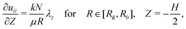 | (28) |
and the virtual work done by friction equals the true work (10) which can be alternatively written as| |  | (29) |
Since this result is path-independent§Ef = −W behaves as an effective potential, in analogy to the Rayleigh dissipation potential. We can now rewrite the potential energy in the simplified formWe will use this form of the potential energy in our subsequent derivations.
We would like to emphasize that although the present model is limited to quasistatic motion, kinetic friction must be accounted for here if unstable delamination ensues, and will allow us to capture the newly established equilibrium state that follows. This will be explained in more detail in describing the solution procedure.
Torque and normal force
The above formulation is derived assuming a prescribed rotation angle – α, and deformed height – h = λzH. Hence, the corresponding generalized forces, i.e. the torque – T, and the normal force – N (defined positive in compression as shown in Fig. 1, where the compressive force F is equivalent to the quantity N discussed in this section), do not naturally emerge from the formulation. Nonetheless, a direct method to obtain them at a given state (i.e. with given Rd), is by considering perturbations of the elastic energy with respect to the corresponding generalized coordinate, which translates to the partial derivatives| |  | (31) |
Though these derivatives can only be calculated a posteriori, they will be useful for comparison with the experimental observations.
Energy minimization
The above formulation consists of a single second order, partial differential eqn (15) for uθ = uθ(R,Z), complemented by conditions on the different regions of the boundary (16)–(18) and (28). This completes our boundary value problem, but for a prescribed location of the delamination front Rd and for a given α. To determine Rd(α), the location of the delamination front as rotation progresses, we must invoke the second requirement in (13). This requirement implies that the system should choose the location of the delamination front to minimize the total potential energy of the system. Though the dependence on Rd is not explicit in U and thus the differentiation cannot be done analytically, identifying the location of the front can be achieved numerically by considering all different candidate values of Rd and finding the one that corresponds to the minimal potential energy. This can alternatively be written in the form| |  | (32) |
Solution procedure and snap-through events
The delamination process is not gradual. The build-up of elastic energy in the cylinder is necessary to trigger delamination, which is then abrupt, leading to finite sliding at the interface, before arriving at a new equilibrium state for which kinetic friction is balanced by the elastic forces. Then, once at rest, the adhesive bond is re-established, akin to a static friction, and loading can proceed without immediately inducing additional delamination. It is instructive to notice that this sequence of events is analogous to a one-dimensional stick-slip system, with the applied displacement in the one-dimensional system representing the prescribed angular rotation of the top surface; the deformation of the spring in the one-dimensional system representing the torsional deformation of the cylinder; and the resulting uniaxial motion in the one-dimensional system representing the motion of material particles distributed throughout the surface, along circular trajectories.
In each of the steps of the deformation and delamination process described above (i.e. as α increases), the boundary conditions need to be adjusted accordingly in the solution procedure:
Step I – Initial deformation: In this initial stage of the process, no delamination has occurred. Accordingly, the boundary value problem is solved with Rd = R0 and uθ0 = 0. Nonetheless, at every increment of applied rotation α, solutions with Rd ≤ R0 are examined, employing the shear traction boundary condition (28). Then, the minimum energy requirement (32) is used to determine the location of the propagation front. If Rd = R0, the solution procedure remains in Step I; otherwise, it transitions to Step II.
Step II – Snap-through: Once Rd = R0 no longer provides an energetically favorable solution, a delamination front will propagate, also leading to a drop in the applied torque. Considering a quasistatic process, our model captures the new equilibrium state that the system will choose, which results from the minimum energy requirement (32), as calculated in the previous step. Once the propagation stops, the adhesive bond is re-established and the displacement at the bottom surface is constrained to a new location, namely uθ0 is re-assigned to uθ0(R) = uθ(R, −H/2).
Step III – Secondary deformation: In this step torsional deformation proceeds with no additional delamination. Hence, the boundary value problem is solved with Rd = R0 and uθ0(R) from Step II. Similar to Step I, in this stage of the process, no additional delamination occurs. Nonetheless, at every increment of applied rotation α we examine solutions with Rd ≤ R0 and employ the shear traction boundary condition (28). The minimum energy requirement (32) is again used to determine the location of the propagation front. If Rd = R0 then the solution procedure remains in Step III, otherwise it transitions back to Step II.
All of the numerical derivations are conducted in Matlab. The governing equation in (15) is integrated using a finite difference scheme.
3. Results and sensitivity analysis
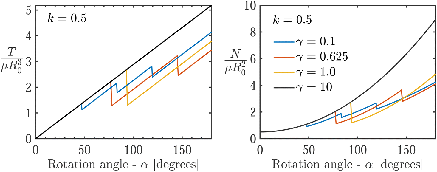
To study the delamination process, we employ the solution procedure described in the previous section. Theoretical results are found both in Fig. 3 (black curves) to compare with experiments, and in dimensionless form in Fig. 5 and 6. In all cases, both the torque and the normal force initially increase monotonically with rotation α. The linear torque response is explained by the linearity of the neo-Hookean model under shear deformation, and the increase in the normal force is consistent with the Poynting effect in large torsional deformations of soft solids.37,38 The sharp drops observed in the curves indicate delamination events, which in the present framework manifest as first-order transitions and thus exhibit a finite drop in the applied load until a new equilibrium state is achieved by the resistance of the frictional force.
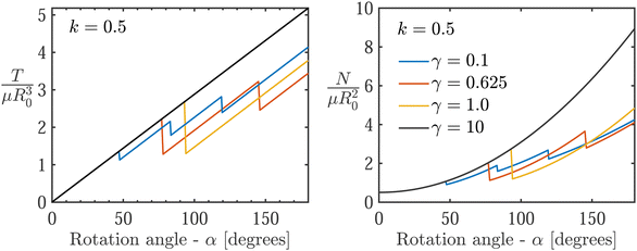 |
| | Fig. 5 The evolution of dimensionless torque (left) and corresponding normal force (right) with respect to rotation angle, for various values of γ. Here we use k = 0.5, R0/H = 1, and the initially applied dimensionless normal force is set to 0.5. | |
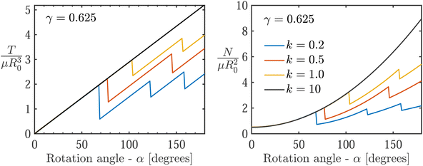 |
| | Fig. 6 The evolution of dimensionless torque (left) and corresponding normal force (right) with respect to rotation angle, for various values of k. Here we use γ = 0.625, R0/H = 1, and the initially applied dimensionless normal force is set to 0.5. | |
Though we do not attempt to fit the experiments and the model, which is limited to cylindrically-symmetric deformations and thus cannot capture the transient propagation of delamination along the circumference, we find that a good qualitative agreement is achieved for k = 0.5 and γ = 0.625 (Fig. 3). These values compare well with reported values in the literature. Reported friction coefficients for similar materials are in the range46k = 0.5–1.5. For the surface toughness, this implies Γ ∼ 53 J m−2, which agrees with recently reported measurements.30 Note that directly measuring the surface properties (i.e. k and Γ) in such soft material interfaces is complicated by the fact that the material itself undergoes nonlinear deformations prior to sliding or delamination.29 This explains the spread of reported values in the literature and the ongoing effort to develop new characterization methods.30 Within this context, the indirect estimates obtained in this work offer an alternative approach.
Further comparing the theoretical and experimental curves in Fig. 3, we find that the theory results in a higher normal force compared to the experiments, which exhibit an artificial decrease in normal force due to initial misalignment (as explained earlier). Note that we do not attempt to compare the theory with experiments for the case with no normal force (i.e. N = 0 [N]) in Fig. 3, since adhesion is not well established in this limit. Nonetheless, among the two considered values (i.e. N = 0.5, 1 [N]), we observe minimal influence of the initial normal force on the torque, consistent with the experiments.
Next, the constitutive sensitivities are investigated by varying the dimensionless interface toughness γ = Γ/μR0 and the friction coefficient k in Fig. 5 and 6, while holding the dimensions of our sample constant with R0/H = 1, and restricting our attention to a normal compression value of N = 0.5 [N]. Snap-through events are observed in all the curves except for γ = 10. For lower values of γ and for the range of considered friction coefficients, k, we observe that weaker interfaces (analogous to the cases with low normal force in the experiments) exhibit a larger number of stick-slip events.
The influence of material parameters in determining the occurrence of snap-through events is further examined using the phase portrait in Fig. 7. Each point on the phase portrait, associated with a pair (k,γ), corresponds to a theoretical prediction for a system that has reached α = 180 degrees. The number of delamination events within this range is then recorded using the corresponding color. A clear trend emerges, where the number of delamination events increases for weaker interfaces (i.e. smaller γ and k) until a high number of consecutive stick-slip cycles take place, thus arriving at a limit where frictional sliding and stick-slip become indistinguishable.
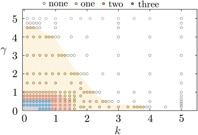 |
| | Fig. 7 Phase portrait showing the number of stick-slip events that occur for rotation of α = 180 degrees, as a function of the dimensionless material properties (k,γ). Different shaded regions correspond to different numbers of delamination events, as identified from theoretical predictions, indicated via circular markers. The gray region corresponds to situations in which the number of snap-through events is greater than 4. | |
4. Conclusion
Soft adhesive solids are becoming ubiquitous due to their advantages over traditional joining techniques. This renders the understanding of their mechanical behavior and failure under various settings vital. Here, relevant physical phenomena to their mechanical behavior, failure and self-healing under combined compression-torsion loading are experimentally investigated and reported. A minimal theoretical framework is provided as an attempt to have a basic understanding of the observed phenomena, and it is shown to be in qualitative agreement with the experimental observations. There is a breadth of opportunities to extend the theoretical model to include fracture in the bulk, examine the response for different constitutive models that incorporate strain stiffening, viscoelasticity, and compressibility, to investigate the change in adhesive strength from one delamination to the next, and to expand the framework to capture the role of inertia or non-rigid substrates. In addition, the experiments could be broadened to test a greater range of radius-to-height aspect ratios and different PDMS base:cross-linker ratios, to determine how changes in the geometric and material parameters may affect the properties of the adhesive bond and the delamination phenomena discussed above.
Conflicts of interest
There are no conflicts to declare.
Acknowledgements
The authors acknowledge the support from the National Science Foundation under award number CMMI-1942016. T. K. V. acknowledges the Barry Goldwater Scholarship and the support of the MIT Undergraduate Research Opportunities Program.
References
- M. Alfano, C. Morano, F. Moroni, F. Musiari, G. D. Spennacchio and D. Di Lonardo, Procedia Struct. Integr., 2018, 8, 561–565 CrossRef.
- A. Kinloch, Proc. Inst. Mech. Eng., Part G, 1997, 211, 307–335 CrossRef.
- G. Davies, D. Hitchings and J. Ankersen, Compos. Sci. Technol., 2006, 66, 846–854 CrossRef.
- M. Barzegar and M. Mokhtari, J. Adhes., 2020, 96, 1431–1448 CrossRef CAS.
-
G. C. Mays and A. R. Hutchinson, Adhesives in civil engineering, Cambridge University Press Cambridge, UK, 1992, vol. 32 Search PubMed.
- O. Buyukozturk and B. Hearing, J. Compos. Constr., 1998, 2, 138–144 CrossRef CAS.
- H. Rahimi and A. Hutchinson, J. Compos. Constr., 2001, 5, 44–56 CrossRef.
- O. Buyukozturk, O. Gunes and E. Karaca, Constr. Build. Mater., 2004, 18, 9–19 CrossRef.
-
S. R. Hartshorn, Structural adhesives: chemistry and technology, Springer Science & Business Media, 2012 Search PubMed.
- Y. Li, J. Krahn and C. Menon, J. Bionic Eng., 2016, 13, 181–199 CrossRef.
- H. Jiang, E. W. Hawkes, C. Fuller, M. A. Estrada, S. A. Suresh, N. Abcouwer, A. K. Han, S. Wang, C. J. Ploch, A. Parness and M. R. Cutkosky, Sci. Robot., 2017, 2, eaan4545 CrossRef PubMed.
- M. Bowditch and S. Shaw, Adv. Perform. Mater., 1996, 3, 325–342 CrossRef CAS.
- X. Shang, E. Marques, J. Machado, R. Carbas, D. Jiang and L. da Silva, Proc. Inst. Mech. Eng., Part L, 2019, 233, 521–530 Search PubMed.
- M. Banea and L. F. da Silva, Proc. Inst. Mech. Eng., Part L, 2010, 224, 51–62 CrossRef.
- T. Cohen, C. U. Chan and L. Mahadevan, Soft Matter, 2018, 14, 1771–1779 RSC.
- R. R. Collino, N. R. Philips, M. N. Rossol, R. M. McMeeking and M. R. Begley, J. R. Soc., Interface, 2014, 11, 20140453 CrossRef PubMed.
- E. Ringoot, T. Roch, J.-F. Molinari, T. J. Massart and T. Cohen, J. Mech. Phys. Solids, 2021, 155, 104528 CrossRef.
- K. R. Shull, D. Ahn, W.-L. Chen, C. M. Flanigan and A. J. Crosby, Macromol. Chem. Phys., 1998, 199, 489–511 CrossRef CAS.
- J. H. Oh, Compos. Sci. Technol., 2007, 67, 1340–1347 CrossRef CAS.
- Y. Liu, D. He, A.-L. Hamon, B. Fan, P. Haghi-Ashtiani, T. Reiss and J. Bai, Compos. Sci. Technol., 2018, 167, 331–338 CrossRef CAS.
- U. Khashaba, R. Othman and I. M. Najjar, Proc. Inst. Mech. Eng., Part G, 2020, 234, 490–507 CrossRef CAS.
- S. Razavi, M. Ayatollahi, E. Esmaeili and L. Da Silva, European Journal of Mechanics-A/Solids, 2017, 65, 349–359 CrossRef.
- M. D. Bartlett, A. B. Croll, D. R. King, B. M. Paret, D. J. Irschick and A. J. Crosby, Adv. Mater., 2012, 24, 1078–1083 CrossRef CAS PubMed.
- A. Chateauminois, C. Fretigny and L. Olanier, Phys. Rev. E: Stat., Nonlinear, Soft Matter Phys., 2010, 81, 026106 CrossRef PubMed.
- M. Hetenyi and P. H. McDonald Jr., J. Appl. Mech., 1958, 25, 396–401 CrossRef.
- R. Bryant and W. Dukes, Br. J. Appl. Phys., 1965, 16, 101 CrossRef.
- M. Shishesaz and S. Tehrani, J. Adhes., 2020, 96, 1396–1430 CrossRef CAS.
- M. K. Chaudhury and J. Y. Chung, Langmuir, 2007, 23, 8061–8066 CrossRef CAS PubMed.
- T. Henzel, J. Nijjer, S. Chockalingam, H. Wahdat, A. J. Crosby, J. Yan and T. Cohen, Proc. Natl. Acad. Sci. U. S. A., 2022, 1, pgac217 Search PubMed.
- H. Wahdat, C. Zhang, N. Chan and A. J. Crosby, Soft Matter, 2022, 18, 755–761 RSC.
- F. Pérez-Ràfols and L. Nicola, Friction, 2021, 1–14 Search PubMed.
- M. Barquins, R. Courtel and D. Maugis, Wear, 1976, 38, 385–389 CrossRef CAS.
- A. Schallamach, Wear, 1971, 17, 301–312 CrossRef.
- S. Raayai-Ardakani, Z. Chen, D. R. Earl and T. Cohen, Soft Matter, 2019, 15, 381–392 RSC.
- S. Chockalingam, C. Roth, T. Henzel and T. Cohen, J. Mech. Phys. Solids, 2021, 146, 104172 CrossRef CAS.
- J. H. Poynting, Proc. R. Soc. London, Ser. A, 1909, 82, 546–559 Search PubMed.
- L. M. Kanner and C. O. Horgan, J. Thermoelasticity, 2008, 93, 39–61 CrossRef.
- G. Zurlo, J. Blackwell, N. Colgan and M. Destrade, Am. J. Phys., 2020, 88, 1036–1040 CrossRef.
- P. Ciarletta and M. Destrade, J. Inst. Math. Its Appl., 2014, 79, 804–819 CrossRef.
- D. Bigoni, F. Dal Corso, F. Bosi and D. Misseroni, Mech. Mater., 2015, 80, 368–374 CrossRef.
-
D. Bigoni, F. Bosi, F. Dal Corso and D. Misseroni, 50+ Years of AIMETA, Cham, 2022, pp. 229–241 Search PubMed.
- J. D. Eshelby, Philos. Trans. R. Soc., A, 1951, 244, 87–112 CrossRef.
-
J. Eshelby, J. Eshelby, Academic Press, 1956, vol. 3, pp. 79–144 Search PubMed.
- C. Majidi, Mech. Res. Commun., 2007, 34, 85–90 CrossRef.
- J. R. Rice, J. Appl. Mech., 1968, 35, 379–386 CrossRef.
- S. Maegawa, F. Itoigawa and T. Nakamura, Tribol. Int., 2015, 92, 335–343 CrossRef CAS.
Footnotes |
| † Electronic supplementary information (ESI) available. See DOI: https://doi.org/10.1039/d2sm01675c |
| ‡ Note that this formula has been divided by 2π for compactness. |
| § Note that here we restrict our attention to loading, without considering unloading. |
|
| This journal is © The Royal Society of Chemistry 2023 |
Click here to see how this site uses Cookies. View our privacy policy here. 
 Open Access Article
 This Open Access Article is licensed under a Creative Commons Attribution-Non Commercial 3.0 Unported Licence
 *cd
*cd