Biomass-derived carbon sponges for use as sodium-ion capacitor electrodes†
Received
2nd March 2023
, Accepted 14th April 2023
First published on 14th April 2023
Abstract
S-doped carbon sponges have been synthesized via an eco-friendly approach based on a salt-templating strategy followed by an easy S-doping process. Gluconic acid was chosen as a sustainable carbon precursor, sodium carbonate as a low toxicity, water-removable template, and sulfur as an environmentally benign, earth-abundant S-dopant. These carbon sponges are characterized by a 3D structure of thin interconnected carbon walls with a highly disordered structure, dilated mean interlayer spacing (d > 0.36 nm) and high content of electrochemically active covalent sulfur (up to 13% by weight, mainly as thiophene groups). As a result of these properties, they provide high sodium storage capacity at both low and high discharge rates: 524 mA h g−1 at 0.1 A g−1 and 161 mA h g−1 at 10 A g−1. A Na-ion capacitor was assembled with the S-doped carbon sponges with optimized sodium storage performance as the negative electrode and a gluten-derived highly porous 3D carbon (SBET ∼ 2600 m2 g−1) as the positive electrode. The sodium-ion capacitor with an optimized positive-to-negative electrode mass ratio of 1 can be steady cycled with low capacity fade of 0.0022% per cycle, and is able to deliver a high specific energy of 72 W h kg−1 under a high-power regime (24.4 kW kg−1).
1. Introduction
Hybrid metal-ion capacitors (HICs) are emerging energy storage devices that combine the virtues of batteries (high energy density and low self-discharge) and supercapacitors (high power density and lifespan of >105 cycles). They are preferred candidates for applications requiring storage or delivery of a considerable amount of energy in a short time, including regenerative braking, back-up power systems, and even to buffer power fluctuations in electric microgrids. The unique characteristics of HICs are achieved by the combination of a high voltage battery-type electrolyte (generally carbonate-based) with an asymmetric electrode configuration based on distinct (bulk and surface) energy storage mechanisms.1 The most widely-studied and successful cell configuration involves a pre-metallized battery-type negative electrode based on intercalation, alloying, or conversion processes and a supercapacitor-type positive electrode that adsorbs/desorbs the electrolyte anions on/from its surface.2,3
Driven by the success of currently dominant Li-ion batteries, lithium-ion capacitors (LICs) were the first HICs to be developed,4 and are already commercially available. Similar to progress in the battery field, Na-ion hybrid capacitors (NICs) are a more viable alternative to Li-based capacitors, given the scarcity and uneven distribution of lithium reserves and the similar electrochemical nature of the two alkali metals (sodium standard reduction potential is only 0.34 V higher than that of lithium). Remarkably, and unlike the situation for batteries, Na-based hybrid capacitors have been shown to be able to perform similarly or better than LICs.1 In addition, Na-based systems use aluminium as the current collector at the negative electrode, while their lithium-based counterparts require more expensive, heavier copper collectors as lithium alloys irreversibly with aluminium at low potentials.
Electric double layer capacitor (EDLC)-type highly porous carbons seem to satisfy the requirements for the capacitive electrode of HICs, since their working mechanism is based on fast adsorption and desorption of the anions. In contrast, the search for suitable negative electrode materials combining a battery-type mechanism with good performance at the high current densities typical of capacitor operation is still a significant challenge. Indeed, much research is now being devoted to the design of negative electrode materials with improved power characteristics that could help mitigate the kinetic imbalance between the two electrodes.5–7 Disordered carbon materials, particularly non-graphitizable or hard carbons with large mean interlayer spacings (d > 0.36 nm), are able to store sodium cations reversibly within their structural defects and pores, reaching sodium capacities greater than 300 mA h g−1 at low current densities. These features have established them as the best option for NIC negative electrodes.8–10 In addition, HICs containing carbon materials in both electrodes (so-called dual carbon hybrid ion capacitors) are not only characterized by their robustness and cycling stability,11 but also by potential cost-effectiveness, low toxicity and sustainability (e.g. both electrode materials can be prepared from biomass). Regrettably, the capacity of hard carbons (generally obtained as bulky micron-sized particles) is rapidly lost with increased current density due to the high resistance to sodium diffusion through their bulk structure. One way to mitigate these diffusion restrictions is to design carbon material morphologies with short diffusional pathways, locating the final insertion sites closer to the particle surface. To that end, various carbon nanomaterials including graphenic materials,12,13 carbon nanofibers,14,15 carbon nanoparticles16,17 and nanocapsules,18,19 and foam-like or sponge-like carbonaceous structures20,21 have been investigated as sodium stores. A second strategy involves doping or co-doping the carbon materials with heteroatoms such as nitrogen, sulfur, phosphorus, boron or oxygen, that boosts the pseudocapacitive mechanisms for Na insertion via: (i) increasing the density of structural defects in the carbon matrix; (ii) increasing the average interlayer distance between graphenic sheets, thus reducing the ion diffusion barrier; and (iii) their higher affinity towards Na ions.22,23 In some cases, the heteroatom moieties can also participate in reversible redox reactions with sodium, further enhancing the storage performance of the carbon. This is the case of sulfur groups, which have been shown to contribute to sodium storage capacity through cleaving the C–S–C bonds.24
According to the Sustainable Development Goals,25 the production of electrode materials should meet the criteria of sustainability and so, for carbon-based electrodes, biomass is the preferred carbon source. In particular, biomass-derived substances with low melting points are appropriate candidates for synthesizing carbon materials with tailored morphologies by using endo-templating approaches.26 In this paper, we describe the synthesis of an S-doped sponge-like carbon using gluconic acid (melting point ≈ 160 °C) as the carbon precursor, sodium carbonate as a benign, water-removable salt template, and elemental sulfur as an abundant, cheap S-dopant. The resulting S-doped carbon sponges (11.5–13.1 wt% S) combine a highly disordered microstructure with short solid-state ion diffusion pathways and redox active sulfur functionalities, all of which contribute to the fast, pseudocapacitive storage of sodium. They provide high sodium storage capacities of up to 524 mA h g−1 at low current densities and up to 161 mA h g−1 at 10 A g−1. The optimized material was also analyzed as the negative electrode in a full cell NIC assembled with a positive electrode composed of a highly porous carbon sponge (SBET of 2630 m2 g−1) prepared from gluten via an environmentally friendly, salt-templating chemical activation approach. Different electrode mass ratios were investigated, and the NIC built using a positive-to-negative ratio of 1 demonstrated the best performance in terms of cycling stability, with a capacity fade of 0.0022% per cycle over 10![[thin space (1/6-em)]](https://www.rsc.org/images/entities/char_2009.gif) 000 cycles, and the largest energy output under high power conditions (72 W h kg−1 at 24.4 kW kg−1).
000 cycles, and the largest energy output under high power conditions (72 W h kg−1 at 24.4 kW kg−1).
2. Experimental section
2.1. Synthesis of the negative electrode materials
In a typical synthesis, 16 g sodium carbonate (>99.5%, Sigma-Aldrich) was first dissolved in 80 ml water. Then, D-(+)-gluconic acid δ-lactone (GA) (Sigma-Aldrich) was added in a Na2CO3:GA wt ratio of 7:1. This mixture was frozen in liquid nitrogen (−196 °C) and then transferred to a lyophilizer (Telstar Cryodos) and freeze-dried at a temperature of −50 °C and a pressure of 0.06 mbar. The solid thus obtained was pre-carbonized under N2 gas flow at 550 °C for 1 h, following a heating rate of 3 °C min−1. The carbonized product was washed with abundant hot distilled water and then dried in an oven at 120 °C for 3 h. The purified carbon material was mixed with elemental sulfur in a sulfur/carbon wt ratio of 3 and subjected to a heat-treatment (heating rate = 3 °C min−1) in two stages: first, 2 h at 300 °C and, second, 3 h at the final carbonization temperature (600–750 °C). These materials were labelled AGS-T, where T is the temperature of the sulfur doping treatment. In addition, a reference sample was synthesized by heating the pre-carbonized material to 600 °C (following the same two-stage heating program) in the absence of sulfur. This material was labelled AG-600.
2.2. Synthesis of the positive electrode material
Potassium chloride (Merck, ball-milled), potassium carbonate (Merck, ball-milled) and gluten (Sigma-Aldrich) were thoroughly mixed in an agate mortar (K2CO3:KCl:Gluten wt ratio of 0.5:4:1). The mixture was then heat-treated at a temperature of 850 °C (4 °C min−1) under a nitrogen gas flow and held at the maximum temperature for 1 h. The resulting carbon-inorganic salts mixture was washed several times with hot distilled water to remove the inorganic salt particles and finally dried at 120 °C for 3 h. The purified porous carbon was then subjected to a second carbonization treatment at 850 °C for 2 h (heating rate: 5 °C min−1).
2.3. Physicochemical characterization
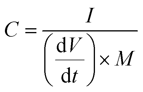
The N2 sorption isotherms were measured at −196 °C using a Micromeritics ASAP 2020 sorptometer. The apparent surface area was calculated by the BET (Brunauer–Emmet–Teller) method using Rouquerol's criteria. The total pore volume was determined from the amount of nitrogen adsorbed at a relative pressure (P/Po) of 0.90. The pore size distributions (PSDs) were determined by the Quenched Solid-state Density Functional Theory (QSDFT) method for nitrogen. Scanning electron microscopy (SEM) images were acquired in a Quanta FEG650 (FEI) instrument. X-ray diffraction (XRD) patterns were obtained on a Bruker D8 Advanced instrument operating at 40 kV and 20 mA, using a Cu-Kα radiation source. The Raman spectra were recorded on a Horiba (LabRam HR-800) spectrometer with a laser source of radiation that operated at a wavelength of 514 nm and a power of 25 mW. The electronic conductivity of the carbon powders was determined in a homemade apparatus in which the powders were placed between two plungers inside a hollow nylon cylinder (inner diameter of 8 mm) and then subjected to a pressure of 7.1 MPa. The formula used for the calculation of the conductivity is:where I is the current (A), h is the height of the sample inside the cylinder (cm), A is the area of the cross section (cm2) and V is the voltage drop (V). Elemental CHN analysis of the samples was carried out on a LECO TruSpec_micror, while the oxygen content was determined on a LECO TruSpec_micro_o and the sulfur content on a LECO S632. X-ray photoelectron spectroscopy (XPS) was carried out with a Specs spectrometer, using Mg KR (1253.6 eV) radiation from a double anode at 150 W.
2.4. Electrochemical characterization
For the preparation of the negative and positive electrodes, aqueous slurries were first prepared from the active material, carbon black (Super C65) and carboxymethylcellulose binder (CMC, Sigma-Aldrich, Mw = 700000) in a weight ratio of 8:1:1. The slurry was stirred overnight and then cast onto a carbon-coated aluminum foil—used as the current collector—by the Doctor Blade technique (Micrometer Adjustable film, EQ-Se-KTQ-SO) using a blade height of 250 μm and automatic lamination equipment (Heating Type Cast Coater, MSK-AFA-HC100). The coated foils were then dried at 105 °C under vacuum overnight and subjected to calendering. Finally, the electrodes were cut with a diameter of 10 mm (the active carbon mass loading was ∼1 mg cm−2). The positive and negative electrodes were first tested in a half-cell configuration, using a Na disc (Merck, ACS Reagent) as reference and counter electrodes. CR2032 coin-type cells were assembled using a 1 mm thick spacer and a wave spring to ensure proper fit. The electrodes were electrically isolated with a 16 mm glass fiber separator (Whatman). The electrolyte consisted of a solution of 1 M NaClO4 in a mixture of ethylene carbonate:diethyl carbonate (EC:DEC, 1:1 by volume, Sigma Aldrich). The electrochemical experiments were performed at room temperature in a computer-controlled potentiostat (Biologic VMP3). Galvanostatic charge/discharge (GCD) experiments were recorded from 0.01 to 3.0 V vs. Na+/Na for the negative electrode and from 2 to 4.2 V vs. Na+/Na for the positive electrode, using current densities that ranged from 0.1 to 10 A g−1. Cyclic voltammetry experiments (CV) were recorded within the same potential windows at sweep rates. Electrochemical impedance spectroscopy (EIS) experiments were carried out after the first sodiation–desodiation cycle and 5 h of resting at open circuit potential, applying a sinusoidal voltage signal with an amplitude of 10 mV and a frequency range from 100 kHz to 1 mHz.
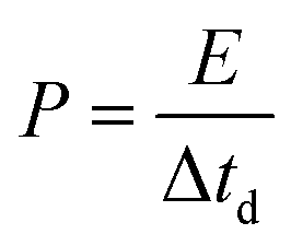
The full NIC cells were assembled using a three-electrode configuration (Swagelok T-cell) with S-doped carbon material as the negative electrode, the microporous carbon as the positive electrode, and a metallic Na disc as the reference electrode. The separator and the electrolyte were the same as those used in the half-cells, and three stainless-steel rods were used as the current collectors. Before full cell assembly, the negative and positive electrodes were pre-conditioned separately to compensate for initial sodium losses. The negative electrode was cycled 3 times at 0.1 A g−1, setting a cut-off potential of 0.05 V vs. Na+/Na. The positive electrode was cycled 5 times between 2 and 4.2 V vs. Na+/Na at 0.1 A g−1, setting a cut-off potential of 4.2 V vs. Na+/Na. Full cells were galvanostatically charged and discharged within the 1–4 V range. Different positive-to-negative electrode active mass ratios (1:1, 1.5:1 and 2:1) were evaluated, in every case keeping a total active mass of ∼2–3 mg cm−2 in the device. The specific capacitance (F g−1), specific energy (W h kg−1), and specific power (W kg−1) of the NICs were calculated using the formulae:
| |  | (2) |
| |  | (3) |
| |  | (4) |
where
I is the current,
M is the total mass of active materials in the positive and negative electrodes, d
V/d
t is the slope of the discharge curve, Δ
Vd is the operation voltage (
Vmax −
IRdrop −
Vmin) and Δ
td is the discharge time.
27
3. Results and discussion
3.1. Physico-chemical properties of the negative electrode materials
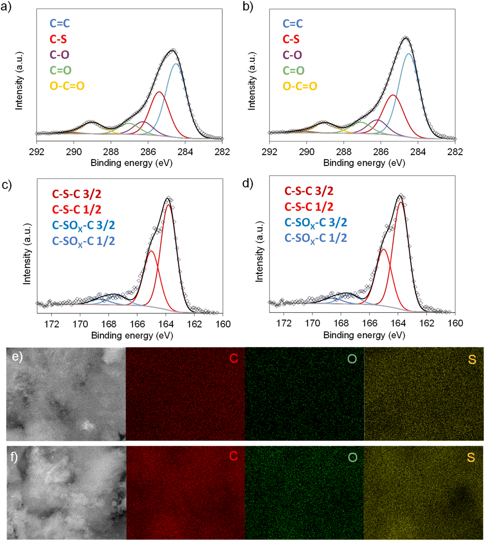
Scheme 1 illustrates the synthesis strategy for the production of the S-doped carbon sponges, which builds upon a simple, eco-friendly salt-templating approach recently reported by our group.25 Briefly, it is based on using: (i) sodium carbonate as an abundant, economic, low toxicity, water-removable salt template, (ii) gluconic acid as a biomass-derived carbon precursor with a low melting temperature (131 °C) and a relatively high carbon yield (i.e., 20%), and (iii) a freeze-drying procedure to induce self-assembly of the Na2CO3 particles into a 3D structure that serves as an endo-template. In order to increase the density of active sites for Na storage, the sponge-like materials were then doped with sulfur heteroatoms by a simple post-treatment at relatively low temperatures (600–750 °C) in the presence of earth-abundant, environmentally benign elemental sulfur. An additional advantage of using sulfur as a dopant is that there is no need for a final purification step, as sulfur evaporates at temperatures above 445 °C. A temperature of 550 °C was selected for the salt template-assisted pre-carbonization given that most of the polymerization/condensation reactions leading to the carbonaceous material have already occurred at this temperature, so that the carbonaceous framework does not collapse on removing the template. In addition, this pre-carbonized material still contains a large number of functional groups that are beneficial for heteroatom attachment during the subsequent doping treatment.28 It should be noted that the direct heat-treatment of the mixture of gluconic acid, sodium carbonate and sulfur leads to a product which is completely soluble in water, making the pre-carbonization process a key step for retaining the sponge-like morphology. The yield of this pre-carbonization step is 23%, while that of the S-doping process falls within the 96–106% range, hence the overall yield of the synthesis process ranges from 22 to 24% (Table 1). The higher yield of the second heat treatment (106% for AGS-600) compared to that of the control, non-doped counterpart (79% for AG-600) clearly hints at substantial S-doping of the material. This was confirmed by the elemental chemical analysis, which shows sulfur content in the 11.5–13.1% range (Table 1). In addition, the materials preserve a high oxygen content of 7.1–11.9%. The chemical environment of the oxygen and sulfur heteroatoms was analyzed by XPS. As Fig. 1a and b show, the high-resolution C 1s spectra of the materials obtained at the lowest and the highest temperatures (AGS-600 and AGS-750) can be deconvoluted into four contributions at 284.5, 286.3, 287.0, 289.0 eV attributable to C![[double bond, length as m-dash]](https://www.rsc.org/images/entities/char_e001.gif) C, C–O, CO and O–CO groups, respectively, as well as one extra, intense peak at 285.4 eV corresponding to the covalently attached sulfur (C–S).29 The high-resolution S 2p spectra in Fig. 1c and d shows that sulfur is mostly present as thiophenic-S (C–Sx–C, doublet at 163.8 and 165 eV), and, to a minor extent (<10%), as oxidized sulfur (C–SOx–C, 167.4 and 168.6 eV).29 This sulfur functionalization is expected to increase the sodium storage capacity of these materials by means of the reversible cleavage and rearrangement of C–S–C bonds.29 Energy dispersive X-ray elemental mappings in Fig. 1e and f show the homogeneous distribution of the sulfur and oxygen functionalities in the carbon sponges. The S-doping process also leads to an enhancement of electronic conductivity by 150% (Table 1), which is highly advantageous for materials targeted at electrochemical applications. Increasing the doping temperature also leads to an additional enhancement of the electronic conductivity (of an order of magnitude for T ≥ 700 °C), which is consistent with a greater degree of condensation/aromatization of the carbonaceous structure.
C, C–O, CO and O–CO groups, respectively, as well as one extra, intense peak at 285.4 eV corresponding to the covalently attached sulfur (C–S).29 The high-resolution S 2p spectra in Fig. 1c and d shows that sulfur is mostly present as thiophenic-S (C–Sx–C, doublet at 163.8 and 165 eV), and, to a minor extent (<10%), as oxidized sulfur (C–SOx–C, 167.4 and 168.6 eV).29 This sulfur functionalization is expected to increase the sodium storage capacity of these materials by means of the reversible cleavage and rearrangement of C–S–C bonds.29 Energy dispersive X-ray elemental mappings in Fig. 1e and f show the homogeneous distribution of the sulfur and oxygen functionalities in the carbon sponges. The S-doping process also leads to an enhancement of electronic conductivity by 150% (Table 1), which is highly advantageous for materials targeted at electrochemical applications. Increasing the doping temperature also leads to an additional enhancement of the electronic conductivity (of an order of magnitude for T ≥ 700 °C), which is consistent with a greater degree of condensation/aromatization of the carbonaceous structure.
 |
| | Scheme 1 Experimental strategy used for synthesis of the S-doped carbon sponges. | |
Table 1 Physico-chemical properties of the carbon sponges
| Carbon material |
Global yielda (%) |
Textural properties |
Structural properties |
Chemical properties |
Electronic conductivityc [S cm−1] |
|
S
BET [m2 g−1] |
V
p0.9
[cm3 g−1] |
d
002 [nm] |
I
D/IG |
C [wt%] |
O [wt%] |
S [wt%] |
|
The yield of the S-doping step is indicated in parenthesis.
Pore volume determined at (P/P0) = 0.90.
Determined at 7.1 MPa.
|
| AG-600 |
18 (79) |
590 |
0.43 |
0.371 |
2.51 |
87.9 |
10.6 |
0 |
0.034 |
| AGS-600 |
25 (106) |
340 |
0.26 |
0.378 |
2.66 |
74.4 |
11.9 |
13.1 |
0.086 |
| AGS-650 |
23 (99) |
450 |
0.33 |
0.380 |
2.69 |
80.4 |
6.4 |
12.8 |
0.083 |
| AGS-700 |
23 (100) |
500 |
0.39 |
0.369 |
2.73 |
79.1 |
7.2 |
12.7 |
0.197 |
| AGS-750 |
22 (96) |
500 |
0.40 |
0.363 |
2.75 |
81.2 |
7.1 |
11.5 |
0.462 |
| AGA-850 |
12 |
2630 |
1.25 |
— |
— |
91.8 |
3.6 |
— |
3.029 |
 |
| | Fig. 1 High-resolution C 1s spectra of (a) AGS-600 and (b) AGS-750; high-resolution S 2p spectra of (c) AGS-600 and (d) AGS-750; EDX mappings of C, O and S for (e) AGS-600 and (f) AGS-750. | |
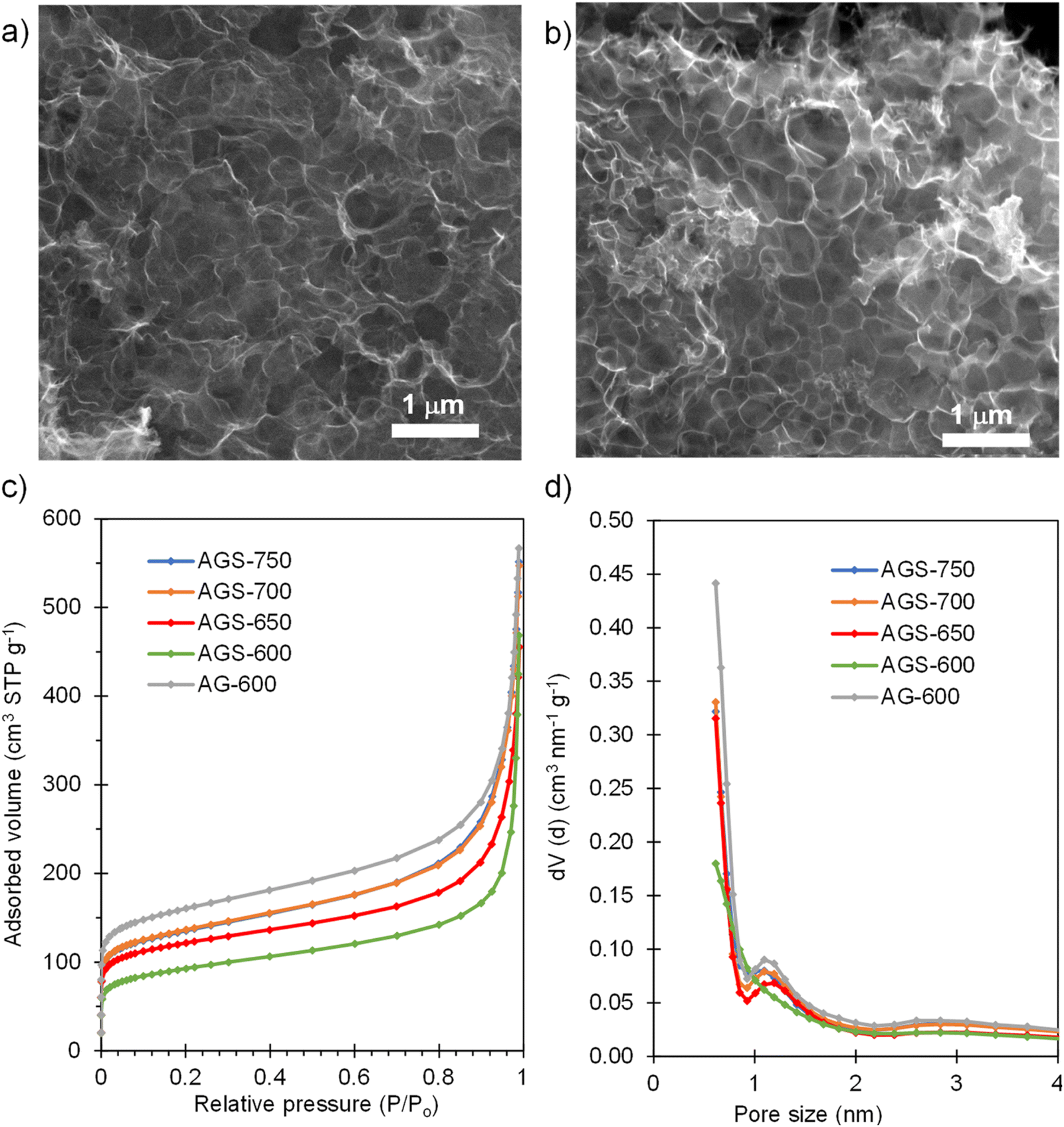
SEM inspection of the S-doped and non-doped materials shows that neither the S-doping process nor the doping temperature modify the sponge-like morphology of the carbons (Fig. 2a and b and Fig. S1†). N2 physisorption experiments were carried out to investigate the effect of doping and doping temperature on the porous structure of the materials. As Fig. 2c shows, the isotherms of the S-doped sponges are type I–IV with significant nitrogen adsorption at relative pressures above 0.9, arising from the presence of the nanosized macropores defined by the sponge-like morphology, and below 0.05, which indicates the presence of certain amount of micropores within the thin carbon walls. This kind of 3D porous structure is very beneficial from a diffusion of species perspective, since it provides rapid access to the active sites even at high rates, as will be demonstrated below. As Table 1 shows, the value of the BET specific surface area and the volume of pores confined within the carbon walls (Vp0.9) rise with the doping temperature from 340 to 500 m2 g−1, and from 0.26 to 0.40 cm3 g−1, respectively. These results may be ascribed to pore opening as a result of removing oxygen and sulfur functionalities. On the other hand, the presence of sulfur somehow limits pore development; the control non-doped sample exhibited a slightly larger content of micropores and narrow mesopores (0.43 cm3 g−1) and therefore a higher value of specific surface area (590 m2 g−1). Comparison of pore size distributions in Fig. 2d shows that the decrease of porosity extends over the full range of pores. This observation contrasts with the increased pore development found when raw precursors are used, such as polypyrrole30 and biomass.31
 |
| | Fig. 2 SEM micrograph of (a) AGS-600 and (b) AGS-750; (c) N2 adsorption isotherms and (d) pore size distributions of the non-doped material and materials doped with S at different temperatures. | |
The microstructure of the S-doped carbon sponges was studied by X-ray diffraction and Raman spectroscopy. The diffractograms in Fig. S2a† show broad and low intensity bands at 2θ ∼ 24° and 44°, corresponding to the (002) and (100) diffraction planes of graphitic carbon, indicating a highly disordered microstructure. The average interlayer space (d002), calculated by applying Bragg's equation to the (002) band, falls within the 0.36–0.38 nm range (Table 1). Importantly, the S-doping process causes a certain increase in the average interlayer space (0.371 nm for AG-600 vs. 0.378 nm for AGS-600), which is known to enhance the material's solid-state diffusion properties and sodium storage capacity. The first-order Raman spectra in Fig. S2b,† with broad and overlapping D- and G-bands, confirm the disordered microstructure of the materials. The ID/IG integrated intensity ratios (see deconvolution for AGS-650 in Fig. S2c†) are 2.66–2.75 for the S-doped carbons (Table 1). The lower ID/IG value of 2.51 calculated for the non-doped AG-600 confirms that sulfur doping causes a higher degree of disorder in the materials that is beneficial for pseudocapacitive storage of sodium cations.
3.2. Electrochemical characterization of the negative electrode materials
The sodium storage properties of the S-doped carbon sponges were analyzed in half-cells using metallic Na as both the counter and the reference electrode. Fig. 3a compares the cyclic voltammograms obtained in the potential range of 0.01–3 V vs. Na+/Na for the materials doped at different temperatures and for the non-doped sample. The CV of the non-doped AG-600 is typical of hard carbons, broadening at lower potentials, indicating a storage mechanism based on Na adsorption on defects (i.e., oxygenated functional groups, edges of basal planes, vacancies, etc.). The pair of intensity peaks at the lowest potential can be ascribed to the filling of nanopores, as described by Titirici et al.32 Its S-doped counterpart, AGS-600, exhibits two well-defined pairs of redox signals at 1.77/2.08 V vs. Na+/Na and 1.12/1.78 V vs. Na+/Na, which are assigned to the faradaic redox reactions between sulfur heteroatoms and sodium.24,29 As doping temperature increases, these redox peaks become less intense as a consequence of decreasing sulfur content (it should be noted that no changes in sulfur speciation into less electroactive groups were detected by XPS, see Fig. 1c and d). The first galvanostatic charge/discharge cycle at 0.1 A g−1 is shown in Fig. S3.† During the first sodiation process an irreversible, extra capacity is recorded for all the materials, which corresponds to the decomposition of the electrolyte and the formation of the solid electrolyte interface (SEI) layer at the negative electrode surface. The initial coulombic efficiency (ICE) values are 49% for non-doped AG-600 and 50–62% for the S-doped materials. These higher values of ICE for the S-doped materials are very important from a practical point of view since lower initial electrolyte consumption imposes lower demands on the negative electrode pre-sodiation process during NIC conditioning.33,34 The galvanostatic profiles of the S-doped sponges corresponding to the second cycle (Fig. 3b) show good reversibility and, in agreement with the CVs, they describe a desodiation (charge) plateau at around 1.5 V and two sodiation (discharge) pseudo-plateaus at ∼1.7 and 1.2 V vs. Na+/Na corresponding to the redox activity of the sulfur functional groups. In contrast, the non-doped material exhibits a sloping profile over the whole potential range, typical of non-doped hard carbons.32
 |
| | Fig. 3 Electrochemical characterization of the negative electrode materials: (a) CVs recorded at a potential sweep rate of 0.1 mV s−1; (b) GCD profiles at 0.1 A g−1 corresponding to the second cycle; (c) impact of the current density on the reversible sodium storage capacity; (d) long-term cycling stability at 0.2 A g−1 for the S-doped carbon sponges and the non-doped material; (e) CVs at different potential sweep rates for AGS-650 (inset: plot of b value); (f) CV recorded at 0.2 mV s−1 for AGS-650, including the pseudocapacitive contribution in green. | |
The sodium storage capacity of the carbon materials was analyzed at different current densities between 0.1 and 10 A g−1. As Fig. 3c shows, the S-doped carbon sponges possess remarkable reversible capacities of 428–515 mA h g−1 at 0.1 A g−1. More importantly, they retain capacities above 140 mA h g−1 at a fast charge–discharge rate of 10 A g−1, which makes them appropriate negative electrode materials for high power systems such as NICs. Compared to the non-doped material, the faradaic contribution of the S-groups means an increase in capacity of 40–70% at low desodiation rates and 100–120% at the highest current rate. Furthermore, when the current density is set back to 0.1 A g−1, all the materials recover the initial capacity, which is indicative of good resilience of the materials microstructure at high charge and discharge rates. Further cycling of the S-doped materials at 0.2 A g−1 for 200 cycles proves their good long-term stability, with a high capacity retention in the range of 80–90% (Fig. 3d) and a coulombic efficiency of 100% during the whole cycling test. The material exhibiting optimum performance in terms of capacity, rate capability, cycling stability and ICE is AGS-650. Its excellent performance must be attributed to the combination of large interlayer spacing (i.e., 0.380 nm), high content of sulfur redox-active heteroatoms (ca. 13%) and high electronic conductivity that helps lowering the ESR of the system (Fig. S4†). Accordingly, this carbon was selected as the negative electrode material for the assembly of the NIC capacitor. As Table S1† shows, the sodium storage performance of AGS-650 is amongst the best reported so far.
To gain further insight into the sodium storage mechanism of the S-doped sponges, a kinetic study was carried out by performing cyclic voltammetry experiments at different potential sweep rates. By fitting the generated current (i) at a given potential with the potential sweep rate (ν) through the power law (i = kνb), it is possible to elucidate the nature of the dominant sodium storage mechanism.35 Thus, a value of b = 0.5 indicates a diffusion-controlled process, and a value of b = 1 is indicative of a surface-driven, pseudocapacitive process. In the case of the non-doped sample AG-600, the kinetic analysis applied to the desodiation peak observed at low potentials (<0.5 V vs. Na+\Na) confirms a pseudocapacitive nature (b = 0.94), typical of insertion processes in structural defects (Fig. S5a†). As for the S-doped materials, the analysis applied to the de-sodiation peak at 1.74 V provides a value of b of 0.85 regardless of the doping temperature (Fig. 3e, S5b and S5c†), also indicating a predominantly pseudocapacitive mechanism. The analysis applied to the non-doped material at the same potential resulted in a comparable value of the b parameter. This proves that the contribution of the redox signal is not limited by species diffusion, and also expresses in a pseudocapacitive manner. The impedance spectroscopy analysis (EIS) showed that these redox processes did not contribute noticeably to the charge transfer resistance (Rct) in the electrodes (Fig. S4†). To quantify the specific contribution of the surface-driven and the diffusion-controlled mechanisms, Dunn's equation was applied to the CV data of the best performing material, AGS-650. According to the equation i(V) = k1ν + k2ν0.5, the total current can be described as the addition of two terms, namely the surface-controlled current (k1ν) and the diffusion-controlled current (k2ν0.5).36 This analysis leads to a pseudocapacitive contribution as high as 84% even at a low voltage sweep rate of 2 mV s−1 (Fig. 3f). This high pseudocapacitive contribution is expected to boost the sodiation–desodiation kinetics, which is crucial for NIC-targeted negative electrodes.
3.3. Physico-chemical properties and electrochemical characterization of the positive electrode material
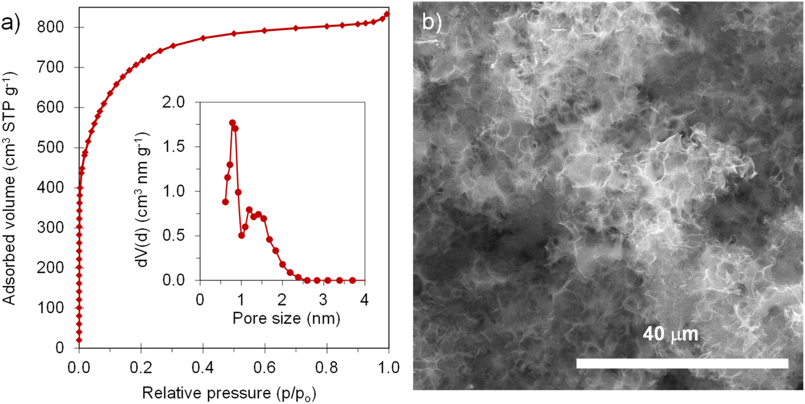
The positive electrode material, labelled AGA-850, was synthesized following a sustainable salt template-assisted chemical activation approach developed by our group, which allows the synthesis of highly porous carbon sponges and is illustrated in Scheme 2. It should be noted, however, that instead of freeze-drying, ball-milled KCl and K2CO3 were used in this case since the selected carbon precursor, gluten, is not soluble in water. Gluten was selected as the carbon precursor on account of its abundance, cost-effectiveness, low glass transition temperature (that allows it to be used in a template-assisted activation), and its nitrogen-rich chemical structure which can boost the porogenic effect of potassium-based salts.37 In this way, even by using a very low K2CO3/gluten weight ratio of 0.5, the highly porous carbon produced achieved a high BET specific surface area of 2630 m2 g−1 and a large pore volume of 1.25 cm3 g−1 (see Table 1). As shown by its type Ib nitrogen adsorption isotherm (Fig. 4a), the material possesses abundant micropores and small mesopores. The PSD in the inset of Fig. 4a shows that these pores are up to ∼3 nm in size. It should be noted that a post-synthesis thermal treatment was applied in order to increase the electronic conductivity of the material. This treatment causes the removal of oxygen functionalities along with a three-fold enhancement of the electric conductivity (Table S2†). As Fig. S6† shows, the textural properties are barely affected by the thermal treatment, registering only a slight widening of the microporosity. Similar to the negative electrode material, AGA-850 shows a 3D sponge-like morphology characterized by interconnected thin nanosheets as a result of the templating effect of the micron-sized KCl and K2CO3 particles (Fig. 4b).
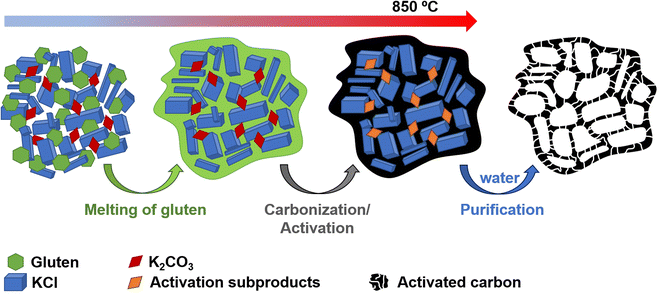 |
| | Scheme 2 Experimental procedure used for the synthesis of AGA-850. | |
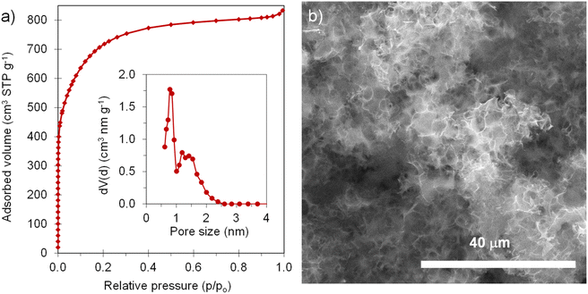 |
| | Fig. 4 (a) N2 adsorption isotherm (inset: QSDFT PSD) and (b) SEM micrograph of AGA-850. | |
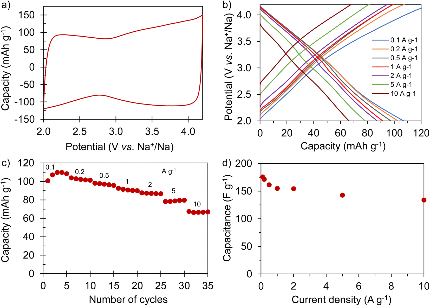
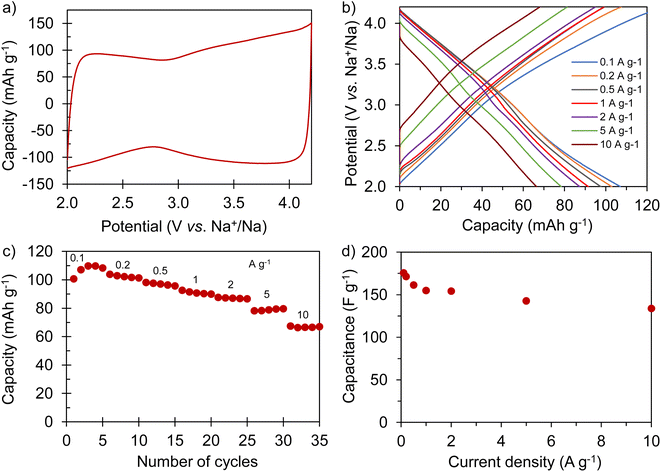
The electrochemical performance of AGA-850 was analyzed within the potential range of 2–4.2 V vs. Na+/Na, which comprises the usual working range of positive electrodes in NICs. The CV curve recorded at 1 mV s−1 (Fig. 5a) exhibits the symmetrical, squared shape typical of capacitive materials. The narrowing around 2.9 V vs. Na/Na+ (agreeing with the value of open circuit potential of the electrode) indicates that adsorption of ClO4− anions occurs at potentials >2.9 V vs. Na/Na+ whilst Na+ cations are adsorbed below this potential. Fig. 5b shows linear galvanostatic charge–discharge potential profiles, confirming the capacitive behavior. As Fig. 5c and d show, the material reaches a maximum capacity of 110 mA h g−1 (176 F g−1) in the 5th cycle at 0.1 A g−1, which is retained to a large extent with increasing current density, providing 67 mA h g−1 (134 F g−1) at a fast charge–discharge rate of 10 A g−1. It is worth highlighting that the second thermal treatment endows the material with a higher capacity and rate capability as a consequence of higher electronic conductivity and probably the slight widening of microporosity (Fig. S7†).
 |
| | Fig. 5 Electrochemical characterization of AGA-850: (a) cyclic voltammogram recorded at 2 mV s−1; (b) galvanostatic charge–discharge potential profiles recorded at different current densities; rate capability expressed in terms of (c) capacity and (d) capacitance. | |
3.4. Electrochemical performance of the sodium-ion capacitor
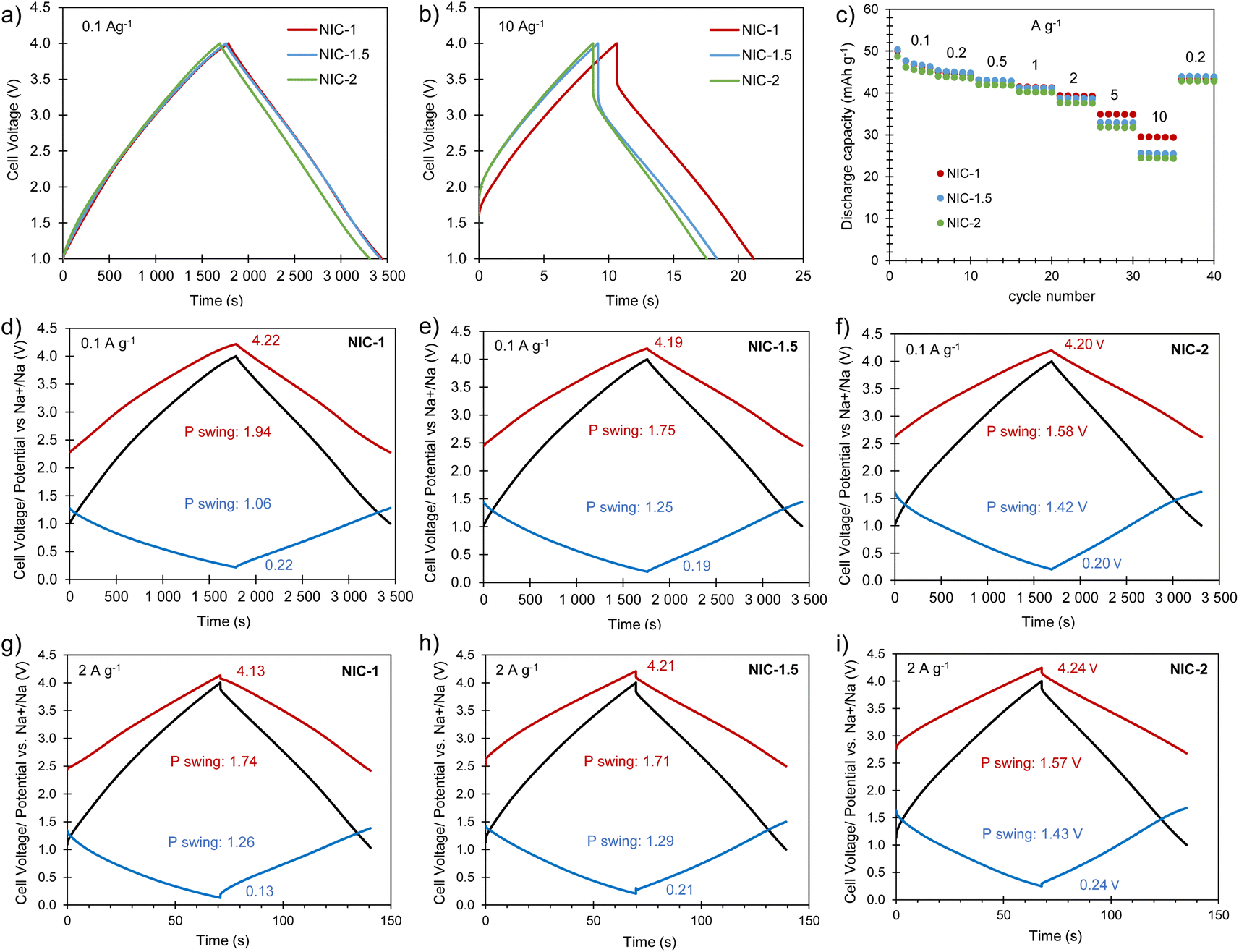
Full cells were built using the best Na store S-doped carbon sponge (AGS-650) as the negative electrode material and the highly porous carbon sponge AGA-850 as the positive electrode material. To optimize the electrochemical performance of the NIC, different positive-to-negative electrode mass ratios of 1:1 (NIC-1), 1.5:1 (NIC-1.5) and 2:1 (NIC-2) were analyzed, keeping the total mass of active material in the cell constant. Before assembling the NICs, the negative and positive electrodes were preconditioned separately in half-cells as detailed in the experimental section. The cells were cycled within the voltage range of 1–4 V at different current densities between 0.1 and 10 A g−1 (based on the total active mass in the cell). The straight voltage profiles displayed by the galvanostatic curves (Fig. 6a and b) confirm the capacitive behavior of the hybrid devices. As Fig. 6c and S8† show, all of the full cells achieve high capacity (and capacitance) values of 49–50 mA h g−1 (53–58 F g−1) at 0.1 A g−1. With increased current density, NIC-1 is better able to retain capacity, delivering as much as 30 mA h g−1 (47 F g−1) at 10 A g−1. The potential swing displayed by each of the electrodes in the full cells at the current densities of 0.1 and 2 A g−1 are shown in Fig. 6d–i. At each current rate, with the increase of the positive-to-negative mass ratio, the positive electrode experiences a narrower potential swing, whilst the negative electrode polarizes within a larger potential range, as expected. For NIC-1, a deeper utilization of the supercapacitor-type electrode (and hence lower utilization of the battery-type electrode) is likely the reason for its better rate capability. At the lowest current rate, the extreme potentials achieved by both electrodes are roughly the same for all of the NICs; with the increased current density, the potential spam of the electrodes evolves differently for each NIC. In all the cases, the lowest potential achieved by the negative electrode is far from 0 V vs. Na+/Na (thus avoiding the risk of dendrite formation), whilst the positive electrode reaches safe maximum potentials below 4.3 V (see Fig. S9† for the determination of the potential window that avoids oxidation of AGA-850).
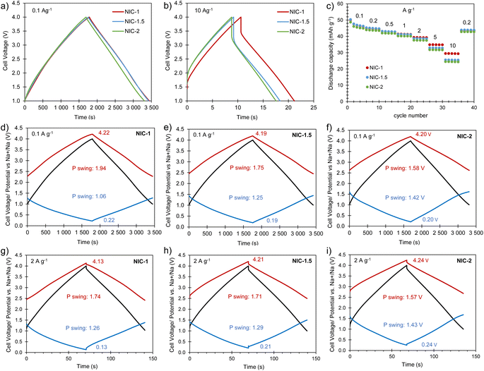 |
| | Fig. 6 Electrochemical characterization of the full cells: (a) galvanostatic charge–discharge profiles recorded at (a) 0.1 A g−1 and (b) 10 A g−1; (c) evolution of capacity with the current density; (d–i) potential/voltage profiles of the full cell (black), positive electrode (red) and negative electrode (blue) of NIC-1, NIC-1.5 and NIC-2 recorded at 0.1 A g−1 and 2 A g−1. | |
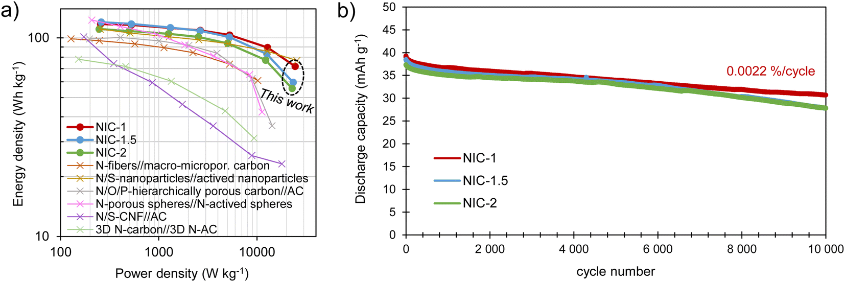
The energy and power performance of the different NICs is combined in the Ragone plot in Fig. 7a. All of the NICs are able to provide maximum energy densities of 111–120 W h kg−1, with NIC-1 retaining the highest energy density, of 72 W h kg−1, at a high-power density of 24.4 kW kg−1. Such an excellent response under high power conditions compares favorably with state-of-the-art sodium-ion capacitors,38–43 and can be attributed to its optimized kinetic balance between the electrodes. These energy/power characteristics are combined with good long-term stability, as tested by 10000 charge/discharge cycles at a current density of 2 A g−1 (Fig. 7b). The best capacity retention is also shown by NIC-1, with a fade of only 0.0022% per cycle, which is likely due to the lower utilization of the battery-type electrode. This slight loss of capacity-which remarks the excellent reversibility of the full cell system-may be ascribed to a minor rise in resistance (the voltage drop increased from 84 to 108 mV) and a small upshift of the negative electrode potential window which, on the other hand, ensures its safe operation (Fig. S10†).
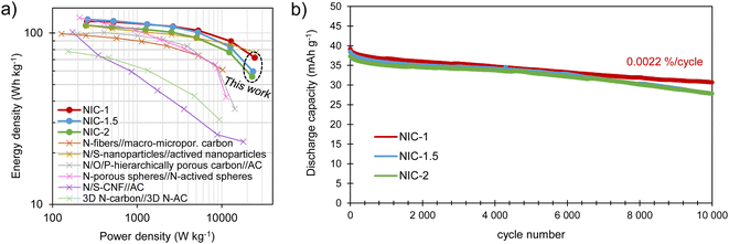 |
| | Fig. 7 (a) Ragone plot showing the energy/power performance of the NICs and (b) long-term cycling test performed at 2 A g−1. | |
4. Conclusions
A sustainable and environmentally friendly synthesis procedure was developed for the production of sponge-like, S-doped carbon materials with a high sodium storage capacity. This method is based on the use of gluconic acid as the carbon precursor, sodium carbonate as an endo-template, and elemental sulfur as a doping agent. The carbon materials achieved a high content of electrochemically active sulfur functional groups (11.5–13.1 wt% of S) and structural defects serving as active sites for Na storage. In addition, their dilated mean interlayer spacing, together with their sponge-like morphology containing thin carbon walls, provides them with a low solid-state diffusion barrier and high accessibility to the active centers. Such chemical and structural features provide the material with high sodium storage capacities (of up to 524 mA h g−1 at 0.1 A g−1) mainly through pseudocapacitive mechanisms, which allow good capacity retention at fast charge and discharge rates (of up to 161 mA h g−1 at 10 A g−1). The material with optimized characteristics, AGS-650, was used as the negative electrode in NICs, using a sponge-like microporous carbon prepared from gluten as the positive electrode material. The hybrid capacitor with a positive-to-negative electrode mass ratio of 1 displayed the best performance in terms of energy and power densities (72 W h kg−1 at 24.4 kW kg−1) and capacity fade on repetitive cycling (0.0022% per cycle).
Conflicts of interest
There are no conflicts to declare.
Acknowledgements
This research was supported by project IDI/2018/000148 (FICYT/FEDER) and PID2021-123648OB-I00 (MCIN/AEI/10.13039/501100011033/and ERDF a way of making Europe).
References
- J. Ding, W. Hu, E. Paek and D. Mitlin, Chem. Rev., 2018, 118, 6457 CrossRef CAS PubMed.
- Y. Zhang, J. Jiang, Y. An, L. Wu, H. Dou, J. Zhang, Y. Zhang, S. Wu, M. Dong, X. Zhang and Z. Guo, ChemSusChem, 2020, 13, 2522 CrossRef CAS PubMed.
- A. Jagadale, X. Zhou, R. Xiong, D. P. Dubal, J. Xu and S. Yang, Energy Storage Mater., 2019, 19, 314 CrossRef.
- G. G. Amatucci, F. Badway, A. Du Pasquier and T. Zheng, J. Electrochem. Soc., 2001, 148, A930 CrossRef CAS.
- S. Dong, N. Lv, Y. Wu, G. Zhu and X. Dong, Adv. Funct. Mater., 2021, 31, 2100455 CrossRef CAS.
- Y. Sun, S. Guo and H. Zhou, Adv. Energy Mater., 2019, 9, 1800212 CrossRef.
- J. Yuan, M. Qiu, X. Hu, Y. Liu, G. Zhong, H. Zhan and Z. Wen, ACS Nano, 2022, 16, 14807 CrossRef CAS PubMed.
- B. Xiao, T. Rojo and X. Li, ChemSusChem, 2019, 12, 133 CrossRef CAS PubMed.
- B. Wang, X. Gao, L. Xu, K. Zou, P. Cai, X. Deng, L. Yang, H. Hou, G. Zou and X. Ji, Batter. Supercaps, 2021, 4, 538 CrossRef CAS.
- D. Saurel, B. Orayech, B. Xiao, D. Carriazo, X. Li and T. Rojo, Adv. Energy Mater., 2018, 8, 1703268 CrossRef.
- T. Panja, J. Ajuria, N. Díez, D. Bhattacharjya, E. Goikolea and D. Carriazo, Sci. Rep., 2020, 10, 10842 CrossRef CAS PubMed.
- H. Wang, D. Mitlin, J. Ding, Z. Li and K. Cui, J. Mater. Chem. A, 2016, 4, 5149 RSC.
- J. Ding, H. Wang, Z. Li, K. Cui, D. Karpuzov, X. Tan, A. Kohandehghan and D. Mitlin, Energy Environ. Sci., 2015, 8, 941 RSC.
- J. Xu, Z. Liu, F. Zhang, J. Tao, L. Shen and X. Zhang, RSC Adv., 2020, 10, 7780 RSC.
- S. Wang, L. Xia, L. Yu, L. Zhang, H. Wang and X. W. Lou, Adv. Energy Mater., 2016, 6, 1502217 CrossRef.
- L. Yang, M. Hu, Q. Lv, H. Zhang, W. Yang and R. Lv, Carbon, 2020, 163, 288 CrossRef CAS.
- G. Wang, M. Shao, H. Ding, Y. Qi, J. Lian, S. Li, J. Qiu, H. Li and F. Huo, Angew. Chem. Int. Ed., 2019, 58, 13584 CrossRef CAS PubMed.
- R. Thangavel, A. G. Kannan, R. Ponraj, G. Yoon, V. Aravindan, D. W. Kim, K. Kang, W. S. Yoon and Y. S. Lee, Energy Storage Mater., 2020, 25, 702 CrossRef.
- J. Ye, J. Zang, Z. Tian, M. Zheng and Q. Dong, J. Mater. Chem. A, 2016, 4, 13223 RSC.
- J. Wang, Z. Xu, J. C. Eloi, M. M. Titirici and S. J. Eichhorn, Adv. Funct. Mater., 2020, 3, 2478 Search PubMed.
- J. Niu, J. Guan, M. Dou, Z. Zhang, J. Kong and F. Wang, ACS Appl. Energy Mater., 2020, 3, 2478 CrossRef CAS.
- D. Li, L. Zhang, H. Chen, L. X. Ding, S. Wang and H. Wang, Chem. Commun., 2015, 51, 16045 RSC.
- G. Zhao, D. Yu, H. Zhang, F. Sun, J. Li, L. Zhu, L. Sun, M. Yu, F. Besenbacher and Y. Sun, Nano Energy, 2020, 67, 104219 CrossRef CAS.
- W. Li, M. Zhou, H. Li, K. Wang, S. Cheng and K. Jiang, Energy Environ. Sci., 2015, 8, 2916 RSC.
-
United Nations Sustainable Development Goals, https://sdgs.un.org/2030agenda, accessed March 2023.
- N. Díez, M. Sevilla and A. B. Fuertes, Carbon, 2021, 178, 451 CrossRef.
- P. A. T. Kelly, C. J. Davis and G. M. Goodwin, Neuroscience, 1988, 25, 907 CrossRef CAS PubMed.
- A. Fombona-Pascual, N. Díez, A. B. Fuertes and M. Sevilla, ChemSusChem, 2022, 15, e202201046 CrossRef CAS PubMed.
- T. Wu, M. Jing, L. Yang, G. Zou, H. Hou, Y. Zhang, Y. Zhang, X. Cao and X. Ji, Adv. Energy Mater., 2019, 9, 1803478 CrossRef.
- N. Díez, M. Sevilla and A. B. Fuertes, Carbon, 2021, 178, 451 CrossRef.
- G. Zhao, D. Yu, H. Zhang, F. Sun, J. Li, L. Zhu, L. Sun, M. Yu, F. Besenbacher and Y. Sun, Nano Energy, 2020, 67, 104219 CrossRef CAS.
- H. Au, H. Alptekin, A. C. S. Jensen, E. Olsson, C. A. O'Keefe, T. Smith, M. Crespo-Ribadeneyra, T. F. Headen, C. P. Grey, Q. Cai, A. J. Drew and M. M. Titirici, Energy Environ. Sci., 2020, 13, 3469 RSC.
- H. Wei, K. Liao, P. Shi, J. Fan, Q. Xu and Y. Min, Nanoscale, 2018, 10, 15842 RSC.
- N. Sun, H. Liu and B. Xu, J. Mater. Chem. A, 2015, 3, 20560 RSC.
- H. Lindström, S. Södergren, A. Solbrand, H. Rensmo, J. Hjelm, A. Hagfeldt and S. E. Lindquist, J. Phys. Chem. B, 1997, 101, 7710 CrossRef.
- J. Wang, J. Polleux, J. Lim and B. Dunn, J. Phys. Chem. C, 2007, 111, 14925 CrossRef CAS.
- M. Sevilla, G. A. Ferrero and A. B. Fuertes, Chem. Mater., 2017, 29, 6900 CrossRef CAS.
- R. Yan, E. Josef, H. Huang, K. Leus, M. Niederberger, J. P. Hofmann, R. Walczak, M. Antonietti and M. Oschatz, Adv. Funct. Mater., 2019, 29, 1902858 CrossRef.
- D. Qiu, C. Yue, C. Qiu, L. Xian, M. Li, F. Wang and R. Yang, Electrochim. Acta, 2022, 405, 139791 CrossRef CAS.
- C. Wang, Q. Yu, N. Zhao, B. Li, W. Shen, F. Kang, Z. H. Huang and R. Lv, J. Mater., 2022, 8, 1149 Search PubMed.
- L. Liu, Y. Lu, S. Wang, Y. Ding, Y. Chen, D. Qiu, D. Wang, J. Niu, J. Zhang, X. Chen and H. Song, J. Colloid Interface Sci., 2022, 620, 24 CrossRef CAS PubMed.
- Q. Yu, T. Dong, R. Qiu and H. Wang, Mater. Res. Bull., 2021, 138, 111211 CrossRef CAS.
- N. Diez, M. Sevilla and A. B. Fuertes, Carbon, 2023, 201, 1126 CrossRef CAS.
|
| This journal is © The Royal Society of Chemistry 2023 |
Click here to see how this site uses Cookies. View our privacy policy here. 
 Open Access Article
 This Open Access Article is licensed under a Creative Commons Attribution-Non Commercial 3.0 Unported Licence
 *
*