 Open Access Article
The phenomenon of “dead” metal in heterogeneous catalysis: opportunities for increasing the efficiency of carbon-supported metal catalysts
Roman M.
Mironenko
 a,
Dmitry B.
Eremin
 bc and
Valentine P.
Ananikov
 *acd
*acd
aCenter of New Chemical Technologies BIC, Neftezavodskaya St. 54, Omsk 644040, Russia
bBridge Institute and Department of Chemistry, University of Southern California, Los Angeles, 90089-3502, USA
cN. D. Zelinsky Institute of Organic Chemistry, Leninsky Pr. 47, Moscow 119991, Russia. E-mail: val@ioc.ac.ru; Web: https://AnanikovLab.ru
dSaint Petersburg State University, 7/9 Universitetskaya Nab., St. Petersburg, 199034, Russia
First published on 20th November 2023
Abstract
This review addresses the largely overlooked yet critical issue of “dead” metal in heterogeneous metal catalysts. “Dead” metal refers to the fraction of metal in a catalyst that remains inaccessible to reactants, significantly reducing the overall catalyst performance. As a representative example considered in detail here, this challenge is particularly relevant for carbon-supported metal catalysts, extensively employed in research and industrial settings. We explore key factors contributing to the formation of “dead” metal, including the morphology of the support, metal atom intercalation within the support layers, encapsulation of metal nanoparticles, interference by organic molecules during catalyst preparation, and dynamic behavior under microwave irradiation. Notably, the review outlines a series of strategic approaches to mitigate the occurrence of “dead” metal during catalyst preparation, thus boosting the catalyst efficiency. The knowledge gathered is important for enhancing the preparation of catalysts, especially those containing precious metals. Beyond the practical implications for catalyst design, this study introduces a novel perspective for understanding and optimizing the catalyst performance. The insights are expected to broadly impact different scientific disciplines, empowered with heterogeneous catalysis and driving innovation in energy, environmental science, and materials chemistry, among others. Exploring the “dead” metal phenomenon and potential mitigation strategies brings the field closer to the ultimate goal of high-efficiency, low-cost catalysis.
1 Introduction
Supported metal catalysts are widely acknowledged as one of the most impactful categories of heterogeneous catalysts and are extensively utilized in synthetic organic chemistry. Their application extends to large-scale industrial catalytic processes and environmental protection initiatives.1–4 These catalysts are composed of catalytically active transition metals dispersed across cost-effective materials, typically characterized by an expansive surface area and well-developed porosity. Economically, supported metal catalysts offer advantages in terms of stability and durability of use, primarily due to the tuned arrangement of metals (particularly, precious metals). This is achieved by distributing the metal particles across the support, which effectively maximizes the metal's active surface area at low metal loadings and small particle sizes.Supported metal catalysts generally contain metal nanoparticles (NPs) that vary in size from single units to tens of nanometers. This variance is contingent upon the nature of the support, the preparation conditions, and the catalyst's pretreatment. As the size of metal NPs expands, the proportion of surface metal atoms diminishes. It is vital to control the size of metal NPs, as only the metal atoms exposed on the NP surface and accessible to reactants constitute the active sites that govern catalytic activity. Conversely, the metal atoms hidden inside the NPs typically do not engage in the catalytic reaction. Metal atom accessibility (or metal dispersion) could be enhanced by supporting small metal clusters or single metal atoms instead of metal NPs.5 Even in these circumstances, however, a reduction in metal accessibility cannot be entirely dismissed due to spatial constraints imposed by the support surface's structural elements. These elements often present a heterogeneous characteristic, marked by various defects and structural imperfections.
The fraction of the supported metal inaccessible to reacting molecules and, consequently, not contributing to catalytic reactions could be referred to as “dead” metal. This “dead” metal phenomenon is a critical issue often encountered in the practical implementation of supported catalysts. If all the supported metal is inaccessible to the molecules, the catalyst will consequently become inactive in the catalytic reaction. The proportion of “dead” metal in supported catalysts can be ascertained through the chemisorption of probe molecules,6,7 an essential step for accurately estimating the specific catalytic activity and turnover frequency. Many studies employ transmission electron microscopy (TEM) to visualize the formation and location of “dead” metal.7–9 For example, a distinctive indicator of “dead” metal's presence is a significantly larger mean size of metal NPs as determined by the chemisorption of probe molecules (apparent size) compared to that determined by TEM measurements (actual size).
The emergence of “dead” metal in supported catalysts can be attributed to numerous factors, including the micro- and macrostructure of a support, conditions of catalyst preparation, heat treatment, and operational conditions. The possible sources of “dead” metal can be broadly divided into those that are (1) difficult or largely impossible to control and those that are (2) controllable, and in some cases, deliberately applied to render a portion of the metal surface inaccessible. This article will survey the issue of uncontrollable metal accessibility loss and the emergence of “dead” metal, specifically using carbon-supported catalysts as examples. We will omit discussion of specific methods to obtain supported catalysts with partially inaccessible (encapsulated) metal NPs.10–14 Additionally, this work will exclude considerations of catalyst deactivation processes occurring during the catalytic reaction, which lead to an increase in the proportion of “dead” metal (metal sintering and active site blockage due to coking and various types of poisoning). These issues have been thoroughly reviewed elsewhere.15–18
Addressing the issue of “dead” metal is critical from a sustainability perspective. Reduction of the quantity of metal used in catalysts is one of the primary objectives and an existing challenge. Avoiding “dead” metal could facilitate the creation of new catalyst designs with enhanced performance attributes and increased turnover number (TON) or turnover frequency (TOF) values. A further consideration is a substantial improvement in cost-efficiency, an effect most pronounced in the case of precious metal catalysis, such as Ir, Rh, Pd, Pt, etc.
The description of “dead” metal as a term has been used in metallurgy and metal processing scholar literature,19,20 dendrite formation and other processes in batteries,21–23 and soluble metal complexes.24 In heterogeneous catalysis, the term “dead” metal was introduced only recently by our study.25 This review delves into a more comprehensive discussion of the term.
Our focus is on carbon-supported metal catalysts, which are among the most prevalent and broadly utilized catalysts in laboratory practice and the chemical industry. Traditionally, activated carbon (AC) types serve as supports for such catalysts. In addition, a range of carbon nanomaterials—such as graphene, carbon nanotubes (CNTs), carbon nanofibers (CNFs), carbon nanospheres, and nanoglobular carbon (NGC)—are currently of significant interest as structurally diverse and well-defined catalyst supports.26–31 Owing to the structural and morphological characteristics of carbon materials, the effects leading to the emergence of “dead” metal are quite pronounced and varied for carbon-supported catalysts. This makes them a suitable system for studying and discussing the “dead” metal phenomenon. Due to size limitations, only some representative examples are discussed in this brief review in order to highlight the main concept.
2 Origins of “dead” metal in M/C catalysts and methods of its “revival”
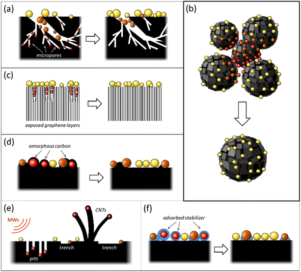
The occurrence of “dead” metal in M/C catalysts is most frequently attributed to pronounced microporosity (especially in the case of ACs) and various structural heterogeneities of the carbon support. These include defects in graphene layers, grain boundaries, and gaps between microcrystallites (Fig. 1a–c). The carbon surface's structural heterogeneities serve as adsorption sites, localizing the metal species during catalyst preparation.30 Several instances of such blockage of metal NPs by fragments of the carbon support have been reviewed previously.32,33 In many situations, the emergence of “dead” metal in M/C catalysts can be associated with the conditions adopted for their preparation. These include high-temperature treatment, microwave (MW) heating, and the usage of surfactants (Fig. 1d–f). The subsequent sections will delve into the causes of the uncontrollable loss of metal accessibility in M/C catalysts and the methods that can prevent the onset of “dead” metal, or “revive” it, thereby improving the catalytic reactivity.2.1 Loss of metal accessibility associated with the influence of carbon support morphology
2.1.1.1 Origin of “dead” metal. Given that various types of AC with well-developed microporosity are widely used as metal catalyst supports, including in industrial applications,2,34 the blockage of active metal in the micropores of ACs is a common event with substantial implications for catalyst activity. This phenomenon can dramatically reduce catalytic activity. This effect has been discussed in the context of palladium and platinum catalysts.32,33,35–43 Metal blockage in micropores occurs when the size of metal NPs aligns with the size of the micropores. Under such circumstances, a significant portion of the metal NP surface trapped in similarly sized micropores comes into close contact with the pore walls, thereby becoming inaccessible to adsorbate or reactant molecules (Fig. 1a). A significant effect of metal blockage can also be observed in certain carbon materials lacking micropores but possessing surface structural imperfections. For instance, certain types of nanoglobular carbon (NGC, also known as carbon black), produced by the furnace process under stringent oxidative conditions, exhibit a relatively rough surface containing narrow, slit-like pores (Fig. 2). These pores on the surface of carbon nanoglobules act as traps for metal clusters and small NPs, contributing to the increased proportion of “dead” metal in catalysts based on furnace types of NGC.30
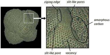 | ||
| Fig. 2 Images of the 3D model of a carbon nanoglobule and a fragment of the model. One could detect the adsorption sites strongly binding metal species on the model surface. Reproduced from ref. 30 with permission of Russ. Chem. Rev. under CC BY license, copyright 2022. | ||
2.1.1.2 Methods of “revival”. When metal NPs are already blocked in the micropores of the carbon support, it is hardly possible to increase the accessibility of the metal surface. Nevertheless, the following measures could be taken to minimize or prevent this phenomenon.
1. Carbon materials in which micropores are absent or only slightly contribute to the total porosity (graphite, thermal kinds of NGC, Sibunit™) may be used as catalyst supports. For example, a nanostructured carbon–carbon composite material Sibunit™ produced by template synthesis has a mesoporous structure with no micropores and thus combines extensive pore space and a high specific surface area.44,45 This carbon material is successfully used, particularly in producing highly efficient palladium catalysts for the industrial processes of liquid-phase hydrogenation, rosin disproportionation, and furfural decarbonylation.
2. During catalyst preparation, large-sized metal compounds (e.g., metal complexes bearing bulky ligands) may be used as precursors because their migration into micropores is prevented by steric reasons, which facilitates metal localization on the outer surface of the carbon support. As an example, one could point to palladium polynuclear hydroxy complexes (PHCs) that are obtained by hydrolysis of H2[PdCl4] with an alkali metal carbonate in a narrow pH range of 4 to 6:
| H2[PdCl4] + K2CO3 → K2[PdCl4] + H2O + CO2, |
| mK2[PdCl4] + 2mH2O → {Kn[Pd(OH)2]m}n+ + (2m − n)K+ + 2mH+ + 4mCl− |
Most often, the particles of Pd PHCs are approximately 3.5 nm in size, and therefore, they could not penetrate the micropores of the carbon support. After the deposition of these complexes on the carbon support and subsequent reduction, the resulting Pd/C catalysts contain accessible Pd NPs and show increased activity in hydrogenation reactions.33,46,47
3. To prepare the M/C catalysts, choosing a method that excludes metal migration into micropores is expedient. For example, the deposition–reduction method31,48 ensures the localization of metal NPs on the outer surface of the support since the rate of formation of metal NPs in the solution bulk during the reduction of the metal precursor is much higher than the rate of diffusion of reactants into the micropores of the support.
2.1.2.1 Origin of “dead” metal. Most carbon nanomaterials used as metal catalyst supports possess a 3D structural organization composed of individual elements such as single- or multiwalled nanotubes, varying morphology nanofibers, nanoglobules of different diameters, etc.28 Usually, these elements' contact areas harbor imperfect structural fragments, including amorphous carbon, characterized by heightened reactivity. These areas function as strong binding sites for metal species during M/C catalyst preparation and can become “dead zones” if reactant molecules' access to localized metal clusters and NPs is spatially limited.
Nanoglobular carbon (NGC) exemplifies this, where carbon nanoglobule accretion areas and aggregate contact points can be hard to reach (Fig. 1b). In a liquid-phase catalytic reaction, NGC-supported metal catalysts form suspensions, the smallest particle size of which is determined by the carbon nanoglobule aggregate size. Varieties of NGC differ significantly in such aggregate and nanoglobule sizes.30,49 For instance, furnace NGCs consist of tens to hundreds of small nanoglobules (10–80 nm) arranged in branched aggregates, possessing a somewhat developed interglobular space teeming with “dead zones”. Supported metal NPs could be obscured from larger adsorbate or reactant molecules.
2.1.2.2 Methods of “revival”. To minimize or avoid “dead” metal appearing in the support's “dead zones”, it is optimal to use carbon materials comprising separate structural elements not in contact with each other. For NGC, thermal types (thermal blacks) composed of large, weakly aggregated, or completely nonaggregated nanoglobules are a better choice.30,49 Palladium catalysts supported on thermal NGC (0.5–2 wt% Pd) display a higher fraction of accessible palladium (i.e., Pd dispersion) and exhibit increased activity (in terms of TOF and substrate conversion) in the liquid-phase hydrogenation of furfural and ethyl 4-nitrobenzoate compared to similar palladium catalysts prepared with furnace-type NGC.47,50,51
The low accessibility of metal localized in the carbon support's “dead zones” can also be circumvented using a single catalyst particle. In recent work, individual 1% Pd/C catalyst particles were separated and isolated from one catalyst batch using a nanomanipulator needle (Fig. 3a).52 For instance, in the 1% Pd/NGC catalyst, such a particle was rounded and contained several thousand Pd NPs. Each isolated catalyst particle was characterized by scanning electron microscopy (SEM), and the analyzed data using a neural network helped determine the number and size of all supported Pd NPs within individual catalyst particles.
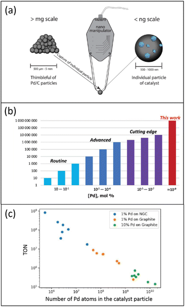 | ||
| Fig. 3 Schematic representation of the characterization and properties of one Pd/C catalyst particle: (a) use of a nanomanipulator to select one catalyst particle; (b) estimation of TONs and loadings for exemplified palladium catalysts in heterogeneous catalytic systems; (c) relationship between TON and the number of Pd atoms in the catalyst particle, according to data of ref. 52, (a) and (b) are reproduced from ref. 52 with permission of American Chemical Society, copyright 2022. The authors prepared (c); no permission was needed. | ||
Contrary to those in the initial catalyst's entire mass with an increased fraction of palladium localized in the “dead zones”, these Pd NPs were fully exposed. In the Suzuki–Miyaura reaction, single-defined 1% Pd/NGC catalyst particles displayed extraordinary TONs of 107–109, unprecedented in heterogeneous catalysis (Fig. 3b). While isolated 1% Pd/graphite particles were also effective (TONs of 105–107), they were less potent than the 1% Pd/NGC particles. A linear negative relationship was found between TON and the number of Pd atoms in the catalyst particle (Fig. 3c). This is most likely due to the increased size/aggregation of metal nanoparticles and the lower ratio of reactant-accessible metal centers upon enlarged overall metal content.
2.2 Intercalation of metal atoms between graphene layers
In the case of carbon nanofibers (CNFs), experiments and model calculations have confirmed the possibility of such penetration by nickel, palladium, and platinum atoms.53–57 This intercalation is especially pronounced with platelet-type CNFs (pCNFs), where the graphene layers are packed perpendicular to the fiber axis, exposing their edges on the fiber surface (a structure often referred to as the card deck structure, Fig. 4a). For instance, Pd/pCNF catalysts showed that palladium atoms could penetrate the bulk of pCNFs, leading to an increased interlayer distance from 3.35 to 3.75 Å at the Pd location. At a relatively low palladium content of 0.04 wt%, the catalyst was inactive in the gas-phase hydrogenation of acetylene (Fig. 4b) due to the complete loss of palladium accessibility to reacting molecules.53
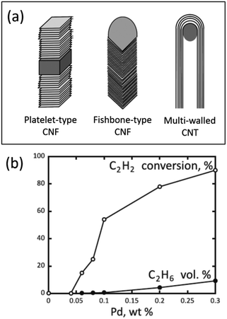 | ||
| Fig. 4 Carbon nanostructures with different arrangements of graphene layers (a) and performance of Pd/pCNF catalysts with different palladium contents in the gas-phase hydrogenation of acetylene in its mixture with ethylene at 90 °C (b). (a) is reproduced from ref. 28 with permission of the Royal Society of Chemistry, copyright 2015, and (b) is reproduced from ref. 53 with permission of Elsevier, copyright 2012. | ||
2.3 Encapsulation of carbon-supported metal NPs by amorphous carbon
Carbon materials created through the pyrolytic destruction of hydrocarbons contain a certain amount of amorphous carbon. This amorphous carbon is primarily located on the surface, predominantly in the areas of accretion or contact of the structural elements of the carbon material and between graphite-like crystallites at their junctions.Amorphous carbon can be represented as a low-density coil of randomly connected low-nuclear carbon clusters, where carbon atoms are mainly sp2-hybridized with some contribution from sp- and sp3-hybridization (see Fig. 2).30 Because of its highly disordered structure, amorphous carbon is characterized by increased reactivity and can strongly bind active metal species. Many carbon atoms in amorphous carbon are mobile at relatively low temperatures. As a result, the structure of amorphous carbon is highly labile and can be affected by adsorbates.32 This lability of amorphous carbon can lead to the encapsulation or blocking of active metal NPs (Fig. 1d), which occurs through different mechanisms.
2.3.1.1 Origin of “dead” metal. In this process, heat-induced migration and agglomeration of carbon atoms and clusters on the catalyst surface lead to contamination or even encapsulation of supported metal NPs by disordered carbon overlayers, resulting in a decrease or complete loss of metal accessibility (Fig. 5). This mechanism has been described for various carbon-supported nickel, palladium, and platinum catalysts in several studies.32,58–62
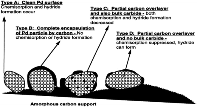 | ||
| Fig. 5 Palladium NPs with various extents of encapsulation by carbon and bulk carbide formation. Reproduced from ref. 60 with permission of Elsevier, copyright 1998. | ||
The formation of carbon overlayers on the surface of metal NPs is affected by the initial conditions for forming NPs from the adsorbed precursor.63,64 If metal atoms formed at the high-temperature decomposition of the precursor strongly interact with the carbon surface, the formation of metal NPs from these atoms will be accompanied by their decoration (contamination) with carbon. In the case of rapid nucleation and growth of metal NPs, the interaction between metal and carbon is diminished, preventing such decoration of metal NPs.
It has been demonstrated in previous studies that thermal treatment of Pd/C and Pt/C catalysts at elevated temperatures stimulates the migration of carbon adatoms into the interior of metal NPs. This process results in the formation of metastable carbides that decompose during high-temperature treatment with hydrogen gas. Furthermore, at temperatures exceeding 600 °C, metal NPs promote the graphitization of amorphous carbon contaminants, preventing further sintering of NPs.58–62
The formation and structure of carbon overlayers on the surface of metal NPs in M/C catalysts are largely influenced by the presence of mobile carbon atoms on the surface of the carbon support, the chemical nature of the adsorbed metal precursor, and the conditions of the thermal treatment of the catalyst.
2.3.1.2 Methods of “revival”. If the carbon support used in the creation of the M/C catalyst is known or suspected to contain significant amounts of amorphous carbon, the encapsulation of metal NPs due to the “high-temperature-condensation” mechanism can be avoided by excluding high-temperature treatments from the catalyst preparation protocol. In this case, using metal precursors that could be easily transformed into metal at room or slightly elevated temperatures is more advantageous. When reduction of metal precursors is necessary, it is preferable to use mild, liquid-phase conditions with reducing agents such as formaldehyde, sodium borohydride, hydrazine, and sodium formate, rather than high-temperature treatment in flowing hydrogen.48
In cases where encapsulation of metal NPs by amorphous carbon cannot be prevented during catalyst preparation, carbon contaminants can be removed by burning them at high temperatures.58–60,63,64 For example, it was shown that the surface of Pd NPs in the 2.8% Pd/NGC catalyst can be cleaned of amorphous carbon through oxidative treatment in a flow of a mixture of 4% O2 and helium at 300 °C, followed by a reduction in hydrogen at 100 °C.58–60 This oxidation-reduction treatment of the catalyst resulted in an almost three-fold increase in TOF in gas-phase benzene hydrogenation.59 However, the heating intensity during such cleaning procedures should be carefully controlled, as there is a risk of sintering metal NPs, which can decrease the dispersion of metal and its accessibility.
2.3.2.1 Origin of “dead” metal. Coating metal NPs by amorphous carbon due to the high-temperature decomposition of metal precursors bearing organic ligands is a phenomenon that can be viewed as a specific instance of the “high-temperature-condensation” mechanism. Here, the metal NP precursor serves as the source of amorphous carbon.
During high-temperature treatment processes (such as reduction in flowing hydrogen), the supported precursor, which contains organic ligands, undergoes decomposition into organic products and metal species. Subsequent condensation (or densification) of these organic products forms disordered carbon overlayers that cover the newly formed metal NPs.
This possibility of amorphous carbon deposition on the surface of Pd NPs due to the thermal decomposition of a precursor containing organic ligands was considered in previous studies58,60 while examining 3% Pd/NGC catalysts prepared from palladium(II) acetylacetonate. Similar results were more recently obtained47,51,65 using palladium(II) acetate and tris(dibenzylideneacetone)dipalladium(0), Pd2(dba)3, as precursors to prepare Pd/NGC catalysts containing 1 or 2 wt% Pd. High-temperature reductive treatment of NGC-supported palladium acetate resulted in the formation of Pd NPs that were partially encapsulated by amorphous carbon (Fig. 6a). A more pronounced effect was observed when using the Pd2(dba)3 complex (Fig. 6b), which is expected given that this precursor is rich in carbon (containing 51 carbon atoms for every 2 palladium atoms). In this case, high-temperature treatment in flowing hydrogen led to the complete encapsulation of the formed NPs, which became inaccessible for the chemisorption of CO molecules. As a result, the Pd/NGC catalysts produced from Pd2(dba)3 showed poor activity (in terms of TOF and substrate conversion) in the liquid-phase hydrogenation of nitro compounds and vinyl derivatives. In contrast, similar catalysts obtained from inorganic palladium precursors (H2[PdCl4], Pd PHCs) contained dispersed Pd NPs and exhibited high activity in the same reactions.
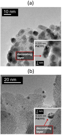 | ||
| Fig. 6 TEM images at different magnifications of the 1% Pd/NGC catalysts prepared by impregnation of the carbon support with solutions of Pd3(OAc)6 (a) and Pd2(dba)3 (b) in chloroform followed by treatment in flowing hydrogen at 300 °C. In both cases, the Pd NPs are encapsulated by amorphous carbon formed during the high-temperature decomposition of these palladium complexes. Reproduced from ref. 47 with permission of Elsevier, copyright 2020. | ||
It is important to note that although the described mechanism contributes to the encapsulation of metal NPs by amorphous carbon and the heat-induced migration and agglomeration of carbon atoms and clusters from the support surface, carbon deposits that form during the thermal decomposition of supported precursors appear to be more labile and easier to remove by high-temperature oxidative treatment compared to those whose source is the carbon support.58,60
2.3.2.2 Methods of “revival”. To avoid the encapsulation of metal NPs by amorphous carbon when using a precursor containing organic ligands to prepare metal-on-carbon (M/C) catalysts, selecting a preparation protocol that eliminates stages of high-temperature treatment is advantageous. A representative example of this can be seen in a straightforward approach for the creation of highly efficient 1% Pd/C catalysts by depositing Pd2(dba)3 from a chloroform solution onto the carbon support at 80 °C.66 Under these conditions, the complex decomposes upon contact with the carbon surface to form Pd NPs. The free dba is then thoroughly removed from the catalyst surface using a solvent. Following this, drying is carried out under gentle conditions without needing high-temperature treatment. The resulting catalysts demonstrate high dispersion of metallic palladium and outstanding performance in both the Suzuki–Miyaura reaction and the transfer hydrogenation of alkenes.
2.3.3.1 Origin of “dead” metal. The “shrinkage-following-swelling” mechanism is a process of unintentional encapsulation of metal NPs that sometimes occurs under mild conditions of metal-on-carbon (M/C) catalyst preparation.32 This encapsulation is often identified in TEM images (Fig. 7), where metal NPs appear as though they have been “pressed” into the carbon network, with surrounding graphene layers orienting parallel to the metal surface close to NPs and more randomly farther away.
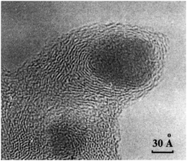 | ||
| Fig. 7 TEM image of a Pd NP encapsulated in the carbon support by the “shrinkage-following-swelling” mechanism. This NP was formed via spontaneous reduction of aqueous H2[PdCl4] by the surface of the furnace NGC at 20 °C. Reproduced from ref. 32 with permission of CRC Press and Taylor & Francis Group, copyright 2003. | ||
In this mechanism, newly formed metal NPs are incorporated into the carbon network due to hydrostatic overpressure (disjoining pressure) occurring in the pores and slits when the support grains interact with the impregnating solution. This way of metal encapsulation occurs when a metal precursor is spontaneously reduced by carbon during impregnation with its aqueous solution. For instance, when H2[PdCl4] comes into contact with the carbon support under certain conditions, it produces Pd NPs.30,32,46
Disjoining pressure is primarily related to the repulsion of double electric layers of the pore walls. As a result, the necks of the pores surrounded by disordered carbon fragments are enlarged due to repulsion forces. Consequently, even if the metal NPs are larger than the diameter of the “dry” pores, this enlargement allows for easy penetration of NPs into the pores. Once the solvent evaporates, the pore walls “collapse”, trapping the metal NPs inside.
2.3.3.2 Methods of “revival”. To avoid this “shrinkage-following-swelling” mechanism when the catalyst preparation conditions favor its implementation (i.e., when the carbon support, metal NPs, and an aqueous phase interact with each other), it is desirable to use a carbon support with a well-ordered structure that lacks slits and micropores. It is plausible that this phenomenon could be prevented by manipulating the electric potential of the carbon surface, such as by changing the pH of the aqueous solution. The closer the electric potential value is to the zero-charge point, the lower the disjoining pressure should be. However, no examples of this principle suppressing metal encapsulation in carbon networks were found.
2.4 Dynamic behavior of carbon-supported metal NPs under microwave heating
Under MW irradiation in the presence of an oxidizer (such as air oxygen), metal NPs burn channels into the carbon support surface and penetrate the carbon support bulk (Fig. 1e). In a vacuum (oxidizer-free conditions), nickel and cobalt NPs can burn channels and also catalyze the growth of carbon nanotubes (CNTs), with the metal NPs remaining encapsulated inside the CNTs.
Further studies have shown that MW irradiation in air can create local hot spots on the metal, leading to significantly increased temperatures.68 For instance, this heat causes palladium NPs to melt and move along the basal carbon surface, creating complexly shaped trenches (Fig. 8a). These hot Pd NPs effectively dissolve carbon and catalyze its oxidation to CO2. The NPs also tend to agglomerate and oxidize to form oxide species during these interactions. The movement of Pd NPs along the surface is limited due to stronger binding with the edges of graphene sheets or defective regions of the carbon surface, leading to penetration into the carbon support.
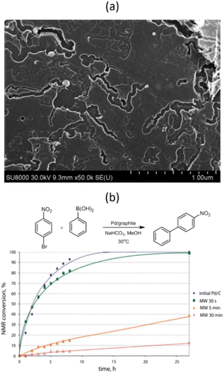 | ||
| Fig. 8 SEM image of the Pd/graphite catalyst after MW treatment in air for 5 min (a) and NMR monitoring of the Suzuki–Miyaura reaction of 1-bromo-4-nitrobenzene with phenylboronic acid in the presence of Pd/graphite catalysts MW-treated for different durations (b). Reproduced from ref. 68 with permission of American Chemical Society, copyright 2017. | ||
The dynamic behavior of carbon-supported metal NPs under MW irradiation can potentially introduce “dead” metal, meaning metal NPs that have either penetrated deep into the carbon support or have become encapsulated within the CNTs formed. These NPs are inaccessible to reacting molecules, which could dramatically affect the catalyst's performance.68 For example, even a short 5 minute exposure of a Pd/graphite catalyst to MW irradiation resulted in a nearly 8-fold decrease in the reaction rate between 1-bromo-4-nitrobenzene and phenylboronic acid (Fig. 8b).
Therefore, it is crucial to consider the dynamic behavior of carbon-supported metal NPs under MW irradiation when preparing M/C catalysts or implementing catalytic reactions over these catalysts using MW heating.
2.5 Blocking of the metal surface by organic molecules adsorbed during catalyst preparation
Despite these advantages, one notable challenge associated with this method is that the organic stabilizer molecules could strongly adsorb onto the metal surface and thus block the catalytically active sites, impairing their catalytic performance (Fig. 1f). Consequently, there is a need for effective strategies for removing these stabilizers from metal NP surfaces without disturbing their size and shape.31
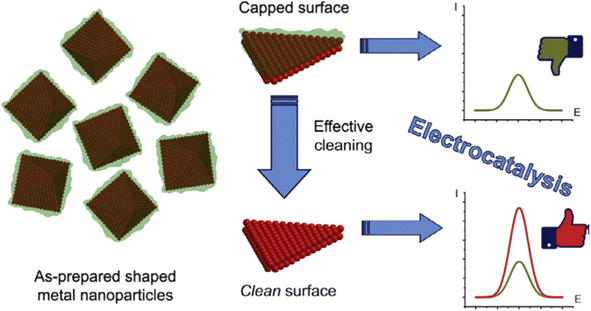 | ||
| Fig. 9 Schematic representation of the surface cleaning of shaped metal NPs, which improves their electrocatalytic performance. Reproduced from ref. 72 with permission of Elsevier, copyright 2017. | ||
2.6 Plausible estimation for “dead” metal
Quantifying “dead” metal – the metal in a catalyst that does not actively participate in the reaction – is crucial for developing highly efficient catalysts. Currently, there are no such universally accepted methods, and researchers can only make estimations. One of the major challenges of such measurements is the objective of quantifying metals that are inactive in a given reaction. Most frequently, the leaching of metal is determined, or recyclability is evaluated. Notably, both are instrumental in understanding the catalytic activity, while these experiments answer the question only indirectly and in part. A detailed investigation of catalyst behavior could provide a better estimate of “dead” metal, but to date, it remains semiquantitative. For example, in the Suzuki–Miyaura and Mizoroki–Heck reactions, it is suggested that only approximately one percent of the total palladium contributes to 99% of the product formation, with the remaining palladium playing a largely passive role.25 This significantly reduces the perceived activity of the catalyst.In heterogeneous catalysts driven by leaching, the nature of metal centers (single atoms, clusters, NPs) determines the generation of active catalytic centers. Leaching is highly possible from accessible metal sites,4,71,74 but unlikely or even impossible from hindered or “dead” metal areas due to restricted access to solvent and reactants.4 The surface of a metal nanoparticle after leaching reveals a previously inaccessible metal, which could generate new catalytically active sites on the surface of a catalyst.
However, it is essential to note that even trace levels of metal can exhibit high catalytic activity, such as in reactions where the catalyst is used in ppm or ppb quantities.75–78 Palladium contamination, sometimes referred to as “homeopathic” levels of Pd, can also catalyze cross-coupling reactions.76,77,79 It is often present in reagents or labware, and can significantly affect the outcome of the reaction.80
Even though these issues highlight that low metal levels can still lead to successful reactions, it is important to scrutinize the estimations of “dead” metal. Detailed mechanistic investigations, particularly kinetic measurements, can help identify and quantify only the catalytically active species.
In heterogeneous catalyst precursors, determining the speciation, types of active centers, and metal atoms that maintain the active catalytic form is essential.81,82 The diversity and distribution of metal-containing species offer multiple opportunities for analytical measurements. Ex situ techniques offer invaluable insights; however, there is always vulnerability to compromise the environment of a catalyst by means of sample preparation or by the measurement itself. Prioritizing operando studies can help understand the amount of “dead” metal and how to avoid it to prepare a catalyst with maximized metal involvement.
Identifying the causes of metal inactivity is a challenging but necessary task. Therefore, further research is needed to accurately quantify the amount of “dead” metal and understand the reasons behind its inactivity.
3 Conclusions
In conclusion, this review, for the first time, conceptualizes the term of “dead” metal within heterogeneous catalysis. The term “dead” metal refers to the inaccessible portion of the metal in a metal–carbon catalytic system. This phenomenon significantly hampers the functional potential of carbon-supported metal catalysts. This important insight can profoundly influence future research strategies and methodologies in catalyst preparation.Preventing or minimizing the formation of “dead” metal during catalyst preparation is feasible, except for some difficult cases, such as irreversible catalyst degradation due to microwave irradiation. This review also provides possible strategies to “revive” dead metal, which, for instance, include the careful burning out of amorphous carbon that encapsulates metal nanoparticles and the removal of stabilizing organic molecules that block the active surface of metal nanoparticles.
Detailed understanding and controlling factors contributing to the formation of “dead” metal during the preparation of metal-on-carbon catalysts, especially those containing precious metals, represent a major challenge. This knowledge could significantly boost the catalyst efficiency and offer a game-changing approach in the preparation of catalysts.
Particularly notable is the demonstrated advantages of nanoglobular carbon as a support for palladium catalysts. The NGC-supported catalysts exhibit high performance in various hydrogenations30,47,50,51,66 and cross-coupling reactions52,66 with a low palladium content, a significant innovation in the field of catalysis.
Indeed, despite having higher palladium loading, some palladium catalysts supported on activated carbon were less efficient due to the blockage of a portion of the palladium nanoparticles in micropores, rendering them inaccessible to reacting molecules. This issue brings to the forefront the need for optimizing catalyst preparation procedures to reduce the catalyst's palladium content by minimizing or preventing the appearance of “dead” palladium.
This review reflects the necessity for a paradigm shift in our understanding of heterogeneous catalysts. It extends beyond just metal-on-carbon catalysts, and the strategies discussed here to prevent the formation of “dead” metal are broadly applicable to other metal catalysts supported on different materials.
The analysis provided here could be a gateway towards creating highly efficient metal catalysts with a maximized amount of “alive” metal involved in the catalytic process. The novelty and impact of this research are undeniable, and it lays the groundwork for a new generation of catalysts composed exclusively of “alive” metal. The concept presented here offers a path towards more efficient, cost-effective, and sustainable catalysis, which will have profound implications for numerous industrial processes.
While our research underscores the paramount significance of optimizing metal efficiency and decreasing inaccessible metal fractions, we urge researchers to apply rigorous considerations. The precise methods and general strategies for catalyst preparation, tailored for specific metal size/dispersion, remain deeply interconnected with the individual catalytic processes in focus. The efficiency characteristics of a catalyst are intricately linked with the specific reaction and its operating conditions. It is pivotal to acknowledge that the proportion of inaccessible metal can be influenced not only by pretreatment protocols but also by dynamic processes that arise during the catalytic reactions themselves. We strongly caution against an oversimplification of our discussions, applying them broadly across heterogeneous catalyst varieties and processes. Instead, we advocate for a nuanced, case-specific examination of the ideas presented herein, ensuring their relevance and adaptability to distinct catalytic systems and conditions.
Author contributions
Roman M. Mironenko – writing – original draft, writing – review & editing: Dmitry B. Eremin – writing – original draft, writing – review & editing: Valentine P. Ananikov – idea, conceptualization, writing – original draft, writing – review & editing.Conflicts of interest
There are no conflicts to declare.Acknowledgements
The authors thank Mr Daniil Boiko for the help in the preparation of Fig. 3c and for helpful discussions. R. M. M. also thanks Prof. Vladimir A. Likholobov for useful discussions. The work was supported by the Ministry of Science and Higher Education of the Russian Federation (project AAAA-A21-121011490008-3). V. P. A. thanks Saint Petersburg State University for the support (project ID 94030064).References
- Supported Metals in Catalysis, ed. J. A. Anderson and M. F. García, Imperial College Press, London, 2nd edn, 2012 Search PubMed.
- D. Yu. Murzin, Engineering Catalysis, Walter de Gruyter, Berlin, 2nd edn, 2020 Search PubMed.
- M. J. Ndolomingo, N. Bingwa and R. Meijboom, J. Mater. Sci., 2020, 55, 6195–6241 CrossRef CAS.
- F. Alonso, I. P. Beletskaya and M. Yus, Tetrahedron, 2005, 61, 11771–11835 CrossRef CAS.
- Supported Metal Single Atom Catalysis, ed. P. Serp and D. P. Minh, Wiley-VCH, Weinheim, 2022 Search PubMed.
- J. L. G. Fierro, Stud. Surf. Sci. Catal., 1990, 57B, B1–B66 Search PubMed.
- G. Bergeret and P. Gallezot, in Handbook of Heterogeneous Catalysis, ed. G. Ertl, H. Knözinger, F. Schüth and J. Weitkamp, Wiley-VCH, Weinheim, 2nd edn, 2008, pp. 738–765 Search PubMed.
- D. S. Su, B. Zhang and R. Schlögl, Chem. Rev., 2015, 115, 2818–2882 CrossRef CAS.
- M. Tang, W. Yuan, Y. Ou, G. Li, R. You, S. Li, H. Yang, Z. Zhang and Y. Wang, ACS Catal., 2020, 10, 14419–14450 CrossRef CAS.
- A. Cao, R. Lu and G. Veser, Phys. Chem. Chem. Phys., 2010, 12, 13499–13510 RSC.
- L. Wang, L. Wang, X. Meng and F.-S. Xiao, Adv. Mater., 2019, 31, 1901905 CrossRef CAS.
- H. O. Otor, J. B. Steiner, C. García-Sancho and A. C. Alba-Rubio, ACS Catal., 2020, 10, 7630–7656 CrossRef CAS.
- C. Gao, F. Lyu and Y. Yin, Chem. Rev., 2021, 121, 834–881 CrossRef CAS.
- A. N. Lebedev, K. S. Rodygin, R. M. Mironenko, E. R. Saybulina and V. P. Ananikov, J. Catal., 2022, 407, 281–289 CrossRef CAS.
- P. Forzatti and L. Lietti, Catal. Today, 1999, 52, 165–181 CrossRef CAS.
- M. D. Argyle and C. H. Bartholomew, Catalysts, 2015, 5, 145–269 CrossRef CAS.
- A. J. Martín, S. Mitchell, C. Mondelli, S. Jaydev and J. Pérez-Ramírez, Nat. Catal., 2022, 5, 854–866 CrossRef.
- E. T. C. Vogt, D. Fu and B. M. Weckhuysen, Angew. Chem., Int. Ed., 2023, 62, e202300319 CrossRef CAS.
- A. R. Eivani and A. Karimi Taheri, Comput. Mater. Sci., 2008, 42, 14–20 CrossRef CAS.
- D. J. Lee, E. Y. Yoon, L. J. Park and H. S. Kim, Scr. Mater., 2012, 67, 384–387 CrossRef CAS.
- M. K. Aslam, Y. Niu, T. Hussain, H. Tabassum, W. Tang, M. Xu and R. Ahuja, Nano Energy, 2021, 86, 106142 CrossRef CAS.
- Z. Shen, J. Mao, G. Yu, W. Zhang, S. Mao, W. Zhong, H. Cheng, J. Guo, J. Zhang and Y. Lu, Angew. Chem., Int. Ed., 2023, 62, e202218452 CrossRef CAS.
- D. Tewari, S. P. Rangarajan, P. B. Balbuena, Y. Barsukov and P. P. Mukherjee, J. Phys. Chem. C, 2020, 124, 6502–6511 CrossRef CAS.
- I. P. Beletskaya and A. V. Cheprakov, in The Mizoroki–Heck Reaction, ed. M. Oestreich, John Wiley & Sons, Chichester, 2009, pp. 51–132 Search PubMed.
- A. S. Galushko, D. A. Boiko, E. O. Pentsak, D. B. Eremin and V. P. Ananikov, J. Am. Chem. Soc., 2023, 145, 9092–9103 CrossRef CAS.
- J. Zhu, A. Holmen and D. Chen, ChemCatChem, 2013, 5, 378–401 CrossRef CAS.
- D. S. Su, in Nanomaterials in Catalysis, ed. P. Serp and K. Philippot, Wiley-VCH, Weinheim, 2013, pp. 331–374 Search PubMed.
- P. Serp and B. Machado, Nanostructured Carbon Materials for Catalysis, The Royal Society of Chemistry, Cambridge, 2015 Search PubMed.
- I. C. Gerber and P. Serp, Chem. Rev., 2020, 120, 1250–1349 CrossRef CAS.
- R. M. Mironenko, V. A. Likholobov and O. B. Belskaya, Russ. Chem. Rev., 2022, 91, RCR5017 CrossRef.
- A. Karczmarska, M. Adamek, S. El Houbbadi, P. Kowalczyk and M. Laskowska, Crystals, 2022, 12, 584 CrossRef CAS.
- P. A. Simonov and V. A. Likholobov, in Catalysis and Electrocatalysis at Nanoparticle Surfaces, ed. A. Wieckowski, E. R. Savinova and C.G. Vayenas, CRC Press, Boca Raton, 2003, pp. 409–454 Search PubMed.
- A. S. Lisitsyn, V. N. Parmon, V. K. Duplyakin and V. A. Likholobov, Ross. Khim. Zh., 2006, 50, 140–153 Search PubMed.
- Industrial Catalytic Processes for Fine and Specialty Chemicals, ed. S. S. Joshi and V. V. Ranade, Elsevier, Amsterdam, 2016 Search PubMed.
- L. B. Okhlopkova, A. S. Lisitsyn, H. P. Boehm and V. A. Likholobov, React. Kinet. Catal. Lett., 2000, 71, 165–171 CrossRef CAS.
- L. B. Okhlopkova, A. S. Lisitsyn, V. A. Likholobov, M. Gurrath and H. P. Boehm, Appl. Catal., A, 2000, 204, 229–240 CrossRef CAS.
- M. Gurrath, T. Kuretzky, H. P. Boehm, L. B. Okhlopkova, A. S. Lisitsyn and V. A. Likholobov, Carbon, 2000, 38, 1241–1255 CrossRef CAS.
- S. A. Kachevskii, E. V. Golubina, E. S. Lokteva and V. V. Lunin, Russ. J. Phys. Chem. A, 2007, 81, 866–873 CrossRef CAS.
- B. N. Kuznetsov, N. V. Chesnokov, N. M. Mikova and T. G. Shendrik, J. Sib. Fed. Univ., Chem., 2008, 1, 3–14 CrossRef.
- L. B. Okhlopkova, Appl. Catal., A, 2009, 355, 115–122 CrossRef CAS.
- R. M. Mironenko, O. B. Belskaya, V. S. Solodovnichenko, T. I. Gulyaeva, Yu. G. Kryazhev and V. A. Likholobov, Kinet. Catal., 2016, 57, 229–233 CrossRef CAS.
- R. M. Mironenko, O. B. Belskaya, Yu. G. Kryazhev, T. I. Gulyaeva and V. A. Likholobov, AIP Conf. Proc., 2019, 2143, 020005 CrossRef.
- J. L. Santos, C. Megías-Sayago, S. Ivanova, M. Á. Centeno and J. A. Odriozola, Appl. Catal., B, 2021, 282, 119615 CrossRef CAS.
- V. A. Likholobov, V. F. Surovikin, G. V. Plaksin, M. S. Tsekhanovich, Yu. V. Surovikin and O. N. Baklanova, Catal. Ind., 2009, 1, 11–16 CrossRef.
- G. V. Plaksin, O. N. Baklanova, A. V. Lavrenov and V. A. Likholobov, Solid Fuel Chem., 2014, 48, 349–355 CrossRef CAS.
- P. A. Simonov, S. Yu. Troitskii and V. A. Likholobov, Kinet. Catal., 2000, 41, 255–269 CrossRef CAS.
- R. M. Mironenko, O. B. Belskaya and V. A. Likholobov, Catal. Today, 2020, 357, 152–165 CrossRef CAS.
- B. A. T. Mehrabadi, S. Eskandari, U. Khan, R. D. White and J. R. Regalbuto, Adv. Catal., 2017, 61, 1–35 CAS.
- C. O. Vogler and M. Voll, in Industrial Carbon and Graphite Materials: Raw Materials, Production and Applications, ed. H. Jäger and W. Frohs, Wiley-VCH, Weinheim, 2021, pp. 533–601 Search PubMed.
- R. M. Mironenko, V. P. Talsi, T. I. Gulyaeva, M. V. Trenikhin and O. B. Belskaya, React. Kinet., Mech. Catal., 2019, 126, 811–827 CrossRef CAS.
- R. M. Mironenko, O. B. Belskaya, L. N. Stepanova, T. I. Gulyaeva, M. V. Trenikhin and V. A. Likholobov, Catal. Lett., 2020, 150, 888–900 CrossRef CAS.
- D. B. Eremin, A. S. Galushko, D. A. Boiko, E. O. Pentsak, I. V. Chistyakov and V. P. Ananikov, J. Am. Chem. Soc., 2022, 144, 6071–6079 CrossRef CAS.
- D. I. Kochubey, V. V. Chesnokov and S. E. Malykhin, Carbon, 2012, 50, 2782–2787 CrossRef CAS.
- V. V. Chesnokov, O. Yu. Podyacheva and R. M. Richards, Mater. Res. Bull., 2017, 88, 78–84 CrossRef CAS.
- C. F. Sanz-Navarro, P.-O. Åstrand, D. Chen, M. Rønning, A. C. T. van Duin and W. A. Goddard III, J. Phys. Chem. C, 2010, 114, 3522–3530 CrossRef CAS.
- Z. Sui, P. Li, J. Zhou, Y. Zhu, D. Chen and X. Zhou, Huagong Xuebao (Chin. Ed.), 2014, 65, 22–31 CAS.
- Y.-X. Tuo, L.-J. Shi, H.-Y. Cheng, Y.-A. Zhu, M.-L. Yang, J. Xu, Y.-F. Han, P. Li and W.-K. Yuan, J. Catal., 2018, 360, 175–186 CrossRef CAS.
- N. Krishnankutty and M. A. Vannice, J. Catal., 1995, 155, 312–326 CrossRef CAS.
- N. Krishnankutty and M. A. Vannice, J. Catal., 1995, 155, 327–335 CrossRef CAS.
- N. Krishnankutty, J. Li and M. A. Vannice, Appl. Catal., A, 1998, 173, 137–144 CrossRef CAS.
- R. Lamber, N. Jaeger and G. Schulz-Ekloff, Surf. Sci., 1990, 227, 15–23 CrossRef CAS.
- R. Lamber and N. I. Jaeger, Surf. Sci., 1993, 289, 247–254 CrossRef CAS.
- J. M. M. Tengco, Y. K. Lugo-José, J. R. Monnier and J. R. Regalbuto, Catal. Today, 2015, 246, 9–14 CrossRef CAS.
- R. Banerjee and J. R. Regalbuto, Appl. Catal., A, 2020, 595, 117504 CrossRef CAS.
- R. M. Mironenko, E. R. Saybulina, L. N. Stepanova, T. I. Gulyaeva, M. V. Trenikhin, K. S. Rodygin and V. P. Ananikov, Catalysts, 2021, 11, 179 CrossRef CAS.
- S. A. Yakukhnov, E. O. Pentsak, K. I. Galkin, R. M. Mironenko, V. A. Drozdov, V. A. Likholobov and V. P. Ananikov, ChemCatChem, 2018, 10, 1869–1873 CrossRef CAS.
- E. O. Pentsak, E. G. Gordeev and V. P. Ananikov, ACS Catal., 2014, 4, 3806–3814 CrossRef CAS.
- E. O. Pentsak, V. A. Cherepanova and V. P. Ananikov, ACS Appl. Mater. Interfaces, 2017, 9, 36723–36732 CrossRef CAS.
- J. A. Delgado, O. Benkirane, C. Claver, D. Curulla-Ferré and C. Godard, Dalton Trans., 2017, 46, 12381–12403 RSC.
- B. Van Vaerenbergh, J. Lauwaert, P. Vermeir, J. De Clercq and J. W. Thybaut, Adv. Catal., 2019, 65, 1–120 CAS.
- I. Beletskaya and V. Tyurin, Molecules, 2010, 15, 4792–4814 CrossRef CAS.
- M. A. Montiel, F. J. Vidal-Iglesias, V. Montiel and J. Solla-Gullón, Curr. Opin. Electrochem., 2017, 1, 34–39 CrossRef CAS.
- H. Pu, H. Dai, T. Zhang, K. Dong, Y. Wang and Y. Deng, Curr. Opin. Electrochem., 2022, 32, 100927 CrossRef CAS.
- V. P. Ananikov and I. P. Beletskaya, Organometallics, 2012, 31, 1595–1604 CrossRef CAS.
- R. K. Arvela, N. E. Leadbeater, M. S. Sangi, V. A. Williams, P. Granados and R. D. Singer, J. Org. Chem., 2005, 70, 161–168 CrossRef CAS.
- I. P. Beletskaya and A. V. Cheprakov, Chem. Rev., 2000, 100, 3009–3066 CrossRef CAS.
- C. Deraedt and D. Astruc, Acc. Chem. Res., 2014, 47, 494–503 CrossRef CAS.
- P.-F. Larsson, A. Correa, M. Carril, P.-O. Norrby and C. Bolm, Angew. Chem., 2009, 121, 5801–5803 CrossRef.
- M. Pérez-Lorenzo, J. Phys. Chem. Lett., 2012, 3, 167–174 CrossRef.
- E. O. Pentsak, D. B. Eremin, E. G. Gordeev and V. P. Ananikov, ACS Catal., 2019, 9, 3070–3081 CrossRef CAS.
- R. H. Crabtree, Chem. Rev., 2012, 112, 1536–1554 CrossRef CAS.
- J. D. Aiken III and R. G. Finke, J. Mol. Catal. A: Chem., 1999, 145, 1–44 CrossRef.
| This journal is © The Royal Society of Chemistry 2023 |

