
 Open Access Article
 This Open Access Article is licensed under a Creative Commons Attribution-Non Commercial 3.0 Unported Licence
Time-resolved enantiomer-exchange probed by using the orbital angular momentum of X-ray light†
Xiang
Jiang
 *a,
Yeonsig
Nam
a,
Jérémy R.
Rouxel
b,
Haiwang
Yong
c and
Shaul
Mukamel
*a
*a,
Yeonsig
Nam
a,
Jérémy R.
Rouxel
b,
Haiwang
Yong
c and
Shaul
Mukamel
*a
aDepartment of Chemistry, Department of Physics & Astronomy, University of California, Irvine, California 92697, USA. E-mail: xiang.jiang@uci.edu; smukamel@uci.edu
bChemical Sciences and Engineering Division, Argonne National Laboratory, Lemont, Illinois 60439, USA
cDepartment of Chemistry and Biochemistry, University of California San Diego, La Jolla, California 92093, USA
First published on 11th September 2023
Abstract
Molecular chirality, a geometric property of utmost importance in biochemistry, is now being investigated in the time-domain. Ultrafast chiral techniques can probe the formation or disappearance of stereogenic centers in molecules. The element-sensitivity of X-rays adds the capability to probe chiral nuclear dynamics locally within the molecular system. However, the implementation of ultrafast techniques for measuring transient chirality remains a challenge because of the intrinsic weakness of chiral-sensitive signals based on circularly polarized light. We propose a novel approach for probing the enantiomeric dynamics by using the orbital angular momentum (OAM) of X-ray light, which can directly monitor the real-time chirality of molecules. Our simulations probe the oscillations in excited chiral formamide on different potential energy surfaces and demonstrate that using the X-ray OAM can increase the measured asymmetry ratio. Moreover, combining the OAM and SAM (spin angular momentum) provides stronger dichroic signals than linearly polarized light, and offers a powerful scheme for chiral discrimination.
1 Introduction
A molecule is chiral if it is not superimposed on its mirror image. The two are known as enantiomers with left and right handedness. Since enantiomers may exhibit radical differences in chemical and biological activity,1–5 monitoring and identifying enantiomers are essential for catalysis6 and drug design.1,7 Fundamental chemical reactions are often based on the reactant kinetics in the electronic ground state while many photochemical reactions rely on the participation of the valence electronic excited state. The chirality of an ensemble of these molecules is defined by the enantiomeric excess with the difference between the molar fractions of the two chiral species, assuming that each molecule is in a given chiral configuration. Chiral molecules in their ground states usually display well separated minima in the ground state potential energy surface (PES) or can racemize over time. If the barrier is not too high, some molecules such as formamide, are achiral in their ground state and display chirality in their excited states. These molecules have typically delocalized nuclear wavepackets over the double well potentials corresponding to the two chiral minima. These nuclear wavepackets can display asymmetric dynamics, and a time-resolved chiral-sensitive technique can be designed to monitor this asymmetry. Discerning the handedness of chiral molecules on different reaction PESs is of considerable interest. With the development of ultrafast laser sources, it has become possible to simultaneously probe molecular chirality on different PESs in real time. Studies that can indirectly or directly observe some dynamical variables such as bond-length and bond-angle changes through Raman8–11 or X-ray12–15 scattering, respectively, have been carried out. However, these techniques fail to discriminate mirror-symmetric structures.To probe molecular chirality, another chiral object must be used, typically light beams. Chiral light beams induce different responses of opposite enantiomers. Dichroic signals due to the asymmetric response of left- and right-handed enantiomers are commonly used to probe molecular chirality. The most common is circular dichroism16–19 (CD) which measures the differential absorption between left and right circularly polarized light. It makes use of the spin angular momentum (SAM) of light, i.e. its polarization state, to probe molecular chirality. Its X-ray extension, XCD, has been demonstrated to be sensitive to the local chiral structure within molecules.20,21 These dichroic signals rely on the cancellation of the achiral contributions to absorption upon subtraction, while the chiral contributions add up. However, CD signals are intrinsically weak since they rely on magnetic transition matrix elements which are usually 10−2 to 10−3 smaller than electric dipoles. This unfavorable scaling stems from the mismatch of the molecular size and light's wavelength.22,23 Photoelectron CD24–27 can be used to enhance the CD signals which leads to an asymmetric forward–backward emission pattern of photoelectrons. Another avenue is to design shaped polarization states of light that maximize the chiral response in nonlinear signals.28–30 One possible way is to create orbital angular momentum (OAM)-carrying beams, also known as vortex or twisted light.
The OAM beams possess screw-shape wavefronts with a spatially twisted profile,31,32 as shown in Fig. 1. These wavefronts have an intrinsic handedness induced by the helical azimuthal contribution.33 Laguerre–Gaussian beams34 are a common type of vortex light carrying an angular phase characterized by the integer helical index l, also known as the topological charge or OAM-value of the beam. Vortex beams are chiral objects that can display an asymmetric interaction with chiral molecules, leading to possible enantiomer discrimination. OAM light has been used in many fields such as telecommunication,35 optical manipulation,36,37 and quantum information.38,39 X-ray vortices were recently shown to be able to selectively detect electronic coherence around conical intersections in ultrafast X-ray diffraction signals.40 OAM beams can be generated by various means including spiral phase plates, spatial light modulators, spiral Fresnel zone plates and helical undulators. The last two are most suitable to create OAM X-ray beams. OAM-carrying beams engage with molecular chirality in a novel way that can be controlled by using the beam OAM value. Earlier work41,42 has highlighted the importance of tightly focused beams to generate appreciable chiral interactions via the longitudinal components of the field along the beam propagation axis. The ability to obtain more tightly focused beams with X-rays than those in the optical regime offers more favorable scaling of these longitudinal components. This allows the chiral interaction between the OAM of X-ray light and matter to be significant in the vicinity of the beam propagation axis.
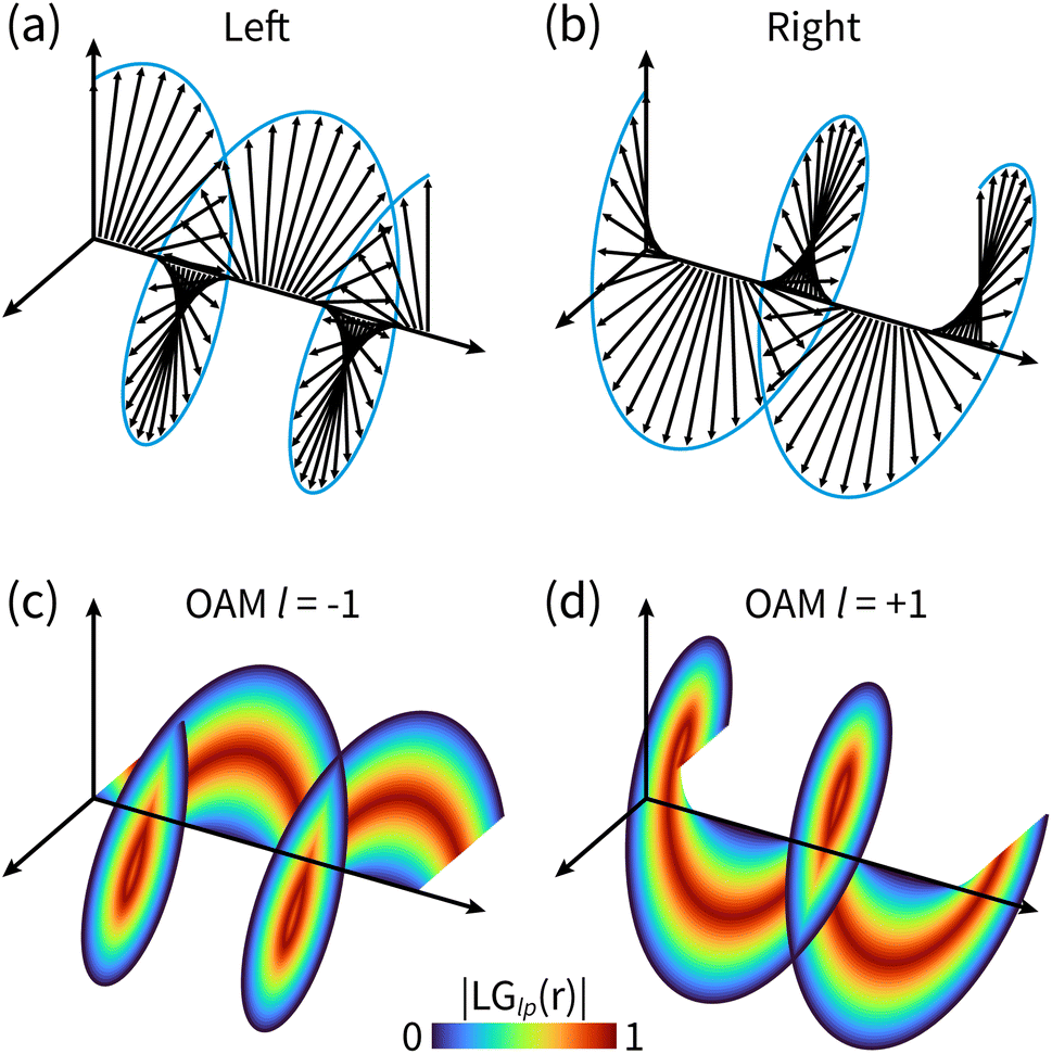 | ||
| Fig. 1 The difference between circularly polarized light and OAM light. (a) and (b) Electric field polarization in left and right circularly polarized light; (c) and (d) helical wavefronts of OAM light for l = ±1. The shown helicoids represent the same phase of the electric field, and the colormap shows the field strength as defined in eqn (5). | ||
The use of an OAM instead of a SAM has recently gained interest42–44 for probing molecular chirality. Here, we introduce a novel time-resolved helical dichroism technique, for monitoring ultrafast molecular chirality by using OAM-carrying X-ray beams.31,34 It captures chiral dynamics in both the ground and excited PESs, and greatly enhances the asymmetric molecular response. Helical dichroism42,44,45 (HD) is a chiral-sensitive technique which measures the differential absorption of positive (+l) and negative (−l) light vortices. This technique was shown to be sensitive to molecular chirality. Here, we extend it to the time domain and use it to probe excited state dynamics. Time-resolved helical dichroism (tr-HD) probes the excited molecules after a delay T from an actinic pump pulse. The technique offers a rich choice of OAM values and offers more flexibility to probe chirality compared to ultrafast CD. The capability to focus X-ray beams down to few tens of nanometers allows better size matching between molecules and field chirality to be obtained. Static experiments43 and simulations42 have already been employed for measuring molecular chirality.
Resonant X-ray interactions are element-sensitive, allowing for additional structural information when combined with chiral sensitivity. In particular, when a molecule possesses a stereogenic (chiral) center, chiral X-ray signals are sensitive to the distance between the probed atom and that chiral center.46 Our recent study47 focused on the loss of chirality of 2-iodobutane upon photodissociation had used time-resolved X-ray CD. We also reported20 a scheme for probing the local molecular chirality by X-ray CD. Other advantages of X-rays such as high spatial resolution, temporal resolution, and large bandwidth have been used to probe quantum dynamics with great accuracy. High-quality OAM or polarized X-ray beams have been demonstrated at synchrotrons48 and free electron lasers,49,50 making the proposed technique readily feasible.
In this study, we use OAM X-rays to monitor the time-evolving enantiomeric exchange in formamide on the ground and excited PESs, by probing several elemental K-edges with various OAM values and light polarizations. We find that time-resolved CD and HD signals are sensitive to the ground and excited state enantiomer dynamics. The HD technique can detect smaller enantiomeric excess and enhances the dichroic response by optimizing the OAM value. Circular-helical dichroism (CHD) signals which combine both the SAM and OAM can significantly enhance the chirality sensitivity. This is consistent with our previous static HD simulation42 of cysteine.
2 The time-resolved helical dichroism signal
We first calculate the transient absorption by using the minimal-coupling light–matter interaction Hamiltonian51,52| Hint = −∫drj(r)·A(r, t), | (1) |
We expand the total molecular wavefunction in the adiabatic basis set
 | (2) |
 | (3) |
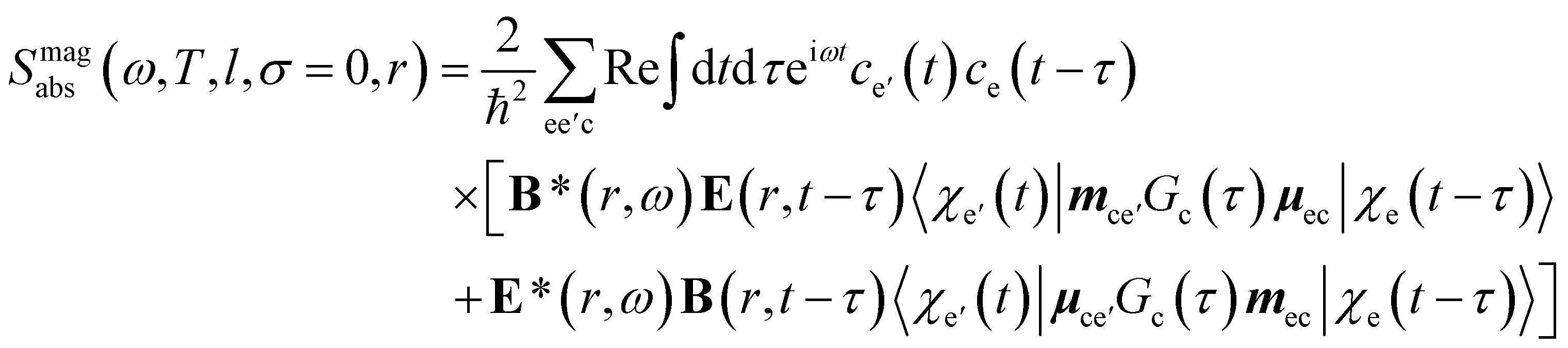
The transient linear absorption is given by
 | (4) |
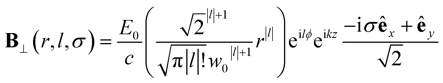
 and
and  is its Fourier transform, dij = 〈φi(r)|A(r)·j(r)|φj(r)〉 is calculated with rotational averaging, ωij = ωi − ωj is the state energy difference, and Γc is the lifetime broadening53 for the core state c. The derivation of eqn (4) and simulation details of wavepacket dynamics are given in the ESI.†
The Laguerre–Gaussian mode used in this paper is a typical OAM beam. The Laguerre–Gaussian beam profile describes the spatial distribution of the electromagnetic field and vector potential involving the OAM. In cylindrical coordinates, the Laguerre–Gaussian mode reads34
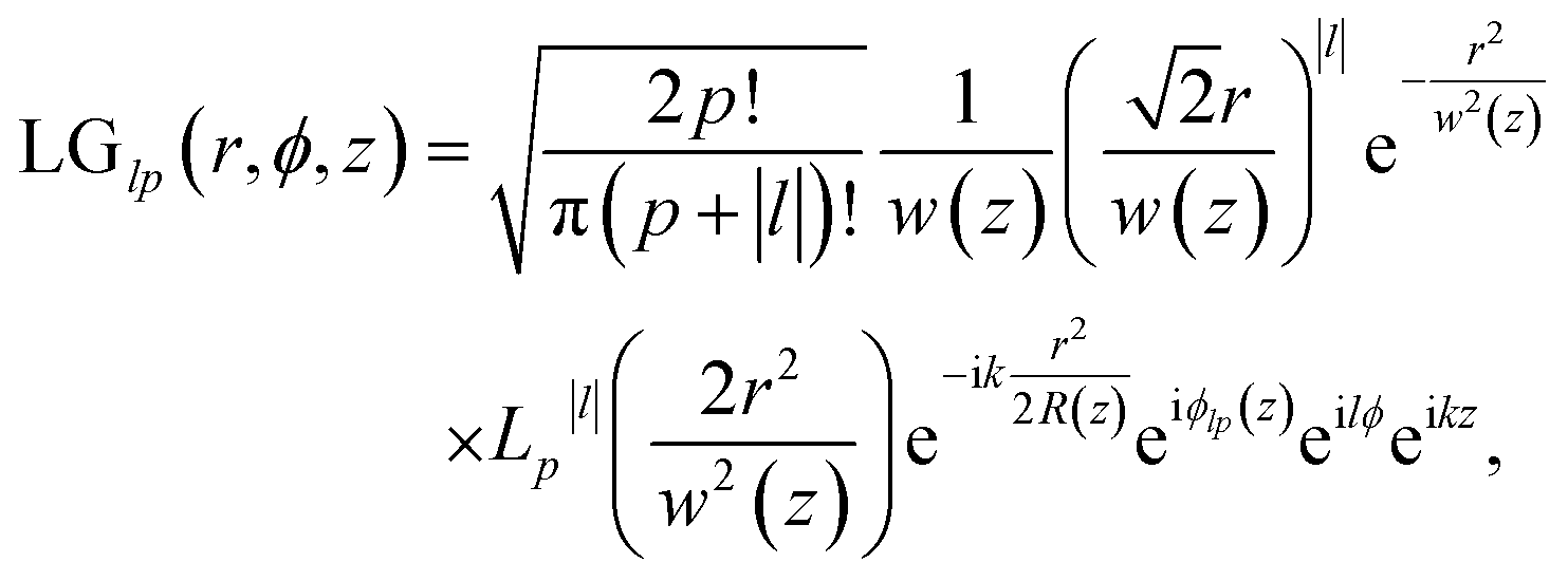 | (5) |
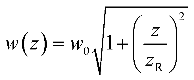 determines the beam width, w0 is the beam waist,
 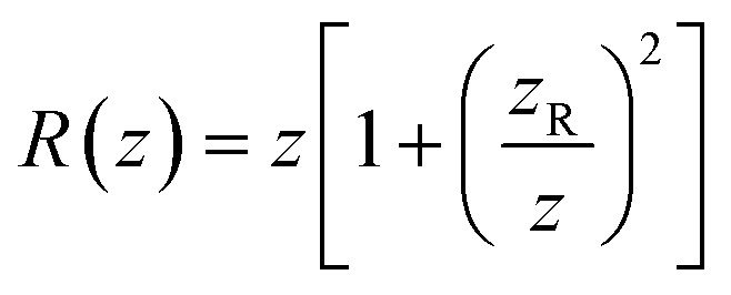 describes the curvature radius,
 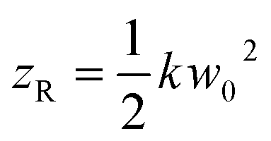 is the Rayleigh length,
 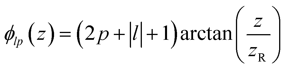 is the Gouy phase, and Lpl(x) is the generalized Laguerre polynomial. The azimuthal index l indicates the beam's OAM and the corresponding phase eilϕ creates different wavefront handedness. Examples of the spatial profiles of the Laguerre–Gaussian beams with l = ±1 are shown in Fig. 1, and compared with that of circularly polarized light. The shown helicoids represent the same phase of the electric field, and the colormap shows the field strength along the radial direction. We can also define the light polarizability by using the spatial part of the electromagnetic vector potential
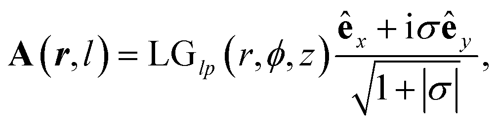 | (6) |
The time-resolved dichroism signal is defined by the normalized transient absorption difference of the left-handed (+l) and the right-handed (−l) Laguerre–Gaussian beams as
 | (7) |
The nature of the interaction of vortex beams with molecular chirality has drawn considerable attention. Our description is based on the minimal coupling Hamiltonian which does not rely on the multipolar expansion and allows the interaction with molecules anywhere within the beam waist to be described. It is possible to connect it to the multipolar approximation when limiting the interaction to molecules in the vicinity of the beam propagation axis. Quinteiro et al.54 and Forbes et al.41 emphasized the importance of longitudinal beam components in the interaction of vortex beams with matter. These components can be recovered within our description by calculating the electric and magnetic fields from the vector potential in eqn (6). In the Lorentz gauge, the scalar potential is given by  The electric and magnetic fields can be calculated at the focal plane and near the center of the vortex beam as:
 | (8) |
 | (9) |
 | (10) |
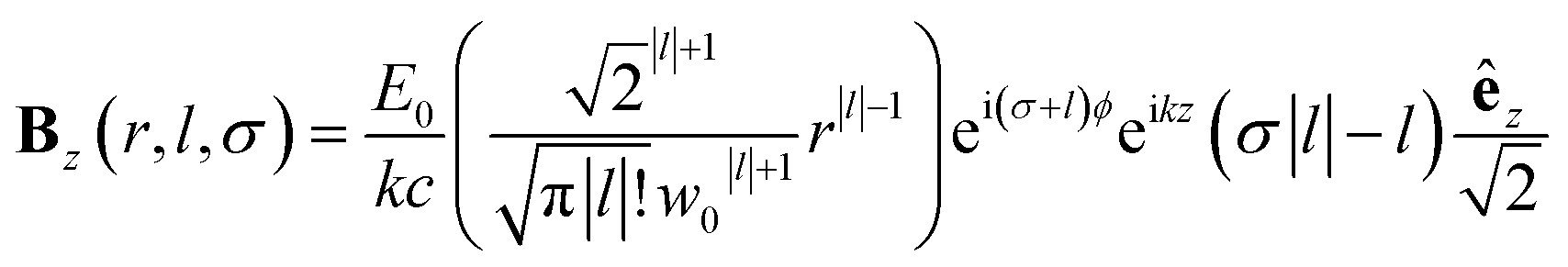 | (11) |
Chiral-sensitive signals have opposite signs for opposite enantiomers. The observed signal must then be expressed as a pseudo-scalar that changes sign upon parity inversion. In CD, the pseudo-scalar is a dot product between electric and magnetic field polarizations. For OAM beams, the factors (|l| − σl) and (σ|l| − l) in the longitudinal components of Ez and Bz respectively, are what allows a pseudo-scalar that does not vanish upon rotational averaging to be created thanks to its opposite sign with respect to l. The 1/k factor in the longitudinal components is unfavorable for X-ray beams but this is compensated by the factor 1/w0|l|+1 since much tighter focusing can be achieved in the X-ray region. This can be readily shown by writing the magnetic contribution to the absorption signal with helical beams for a molecule located at a distance r from the propagation axis:
 | (12) |
To obtain a chiral-sensitive signal, a pseudoscalar must be constructed from the field tensor F(r, l, σ = 0) = B*(r, l, σ = 0) ⊗ E(r, l, σ = 0). Computing the tensor elements using eqn (8)–(11) gives Fzz(r, l, σ = 0) ∝ l|l| which changes sign upon inverting the vortex handedness. This component survives rotational averaging and adds up when calculating the differential absorption of vortex beams with opposite OAM. Thus, near the vicinity of the propagation axis, the leading contribution to the signal is a magnetic dipole–electric dipole two-point correlation function, in a similar way to CD with the added control on the signal strength using the OAM value. This multipolar description is well justified when the molecule is small compared to the beam waist. When the molecules and the beam at focus have comparable size, the multipolar expansion requires a large number of higher multipoles and the minimal coupling description becomes more adequate.
3 Application to formamide
We use our time-resolved dichroism technique based on the pump–probe setup shown in Fig. 2(a) to study the enantiomeric exchange in photoexcited formamide. We use a left circularly polarized actinic pump to trigger an asymmetric excited state wavepacket and a delayed chiral pulse carrying an OAM and/or SAM as a probe. Formamide has an achiral planar geometry at the ground state Franck–Condon point and two chiral non-planar geometries away from that point. This rich handedness makes it an ideal system for studying enantiomer dynamics. With a near-ultraviolet pump, the lowest electron excitation from the ground state is facilitated by promoting an electron from the oxygen lone pair non-bonding orbital to the π* orbital of the C![[double bond, length as m-dash]](https://www.rsc.org/images/entities/char_e001.gif) O bond,55 leading to a pyramidalization of the CHO group and a non-planar chiral conformation. We focus on the nuclear wavepacket dynamics in the out-of-plane bending motion of the CHO group described by the 1170 cm−1 normal mode (orange arrows in Fig. 2(a)). The ultrafast chirality change and the presence of three X-ray chromophores make formamide the most suitable to study the time-dependent chiral process by the tr-HD and tr-CD techniques.
O bond,55 leading to a pyramidalization of the CHO group and a non-planar chiral conformation. We focus on the nuclear wavepacket dynamics in the out-of-plane bending motion of the CHO group described by the 1170 cm−1 normal mode (orange arrows in Fig. 2(a)). The ultrafast chirality change and the presence of three X-ray chromophores make formamide the most suitable to study the time-dependent chiral process by the tr-HD and tr-CD techniques.
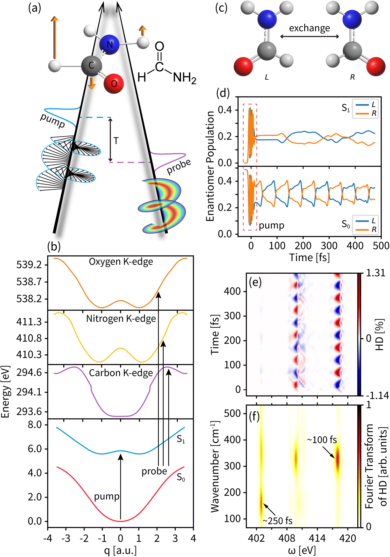 | ||
| Fig. 2 (a) The left circularly polarized light pump and OAM light probe setup acting on formamide based on a vibrational mode shown as the orange arrows. (b) The potential energy curves of the two valence states (S0 for the ground state and S1 for the valence excited state) and the core excited K-edges of carbon, nitrogen, and oxygen. (c) The left- and right-enantiomer geometries of formamide. (d) The enantiomer population of formamide during the dynamics. (e) The entire tr-HD signal for nitrogen with l = 3. (f) The Fourier transform of the tr-HD signal shown in panel (d) for all probe energies. | ||
The electronic structure is calculated by using the MOLPRO package56 at the level of the state-average complete active space self-consistent field (CASSCF57) and the restricted active space self-consistent field (RASSCF58). The ground state geometry optimization and the vibrational frequency are calculated by averaging over three singlet adiabatic states (SA3-CASSCF) consisting of 8 electrons in 8 orbitals in 6-31G* basis sets. The core excited states are then calculated on the 3-state-average SA3-RASSCF(9e, 8o)/6-31G* level by rotating the corresponding core orbitals of C, N, and O into the active space and restricting to the single occupation. Our active space yields the lowest K-edges at 293 eV (C), 411 eV (N), and 538 eV (O), in good agreement with the experiment.59
The PESs of the valence states and the C, N, and O core excitations along the selected normal mode are shown in Fig. 2(b). The parabolic ground state (S0) and the double-well feature of the valence excited state (S1) result in different chiral dynamics on the two PESs. For the planar geometry at the Franck–Condon point and the symmetric structure along the normal mode, probing the chiral dynamics requires an asymmetric excitation of the nuclear wavepacket. A left circularly polarized pump pulse excites the molecule,60 creating an asymmetric nuclear wavepacket both on S0 and S1, as shown in Fig. 2(d) and in Fig. S1† for a few wavepacket snapshots. To measure molecular chirality for delocalized wavepackets over various PESs, we introduce the enantiomer population χeL/R in the e state
 | (13) |
 | (14) |
Fig. 2(d) displays the enantiomer populations in states S0 and S1. As time evolves, the S1 wavepacket exhibits an asymmetric oscillation between the left and right enantiomers with a period of ∼100 fs and a maximum enantiomer population difference of ∼0.2. An unexcited S0 wavepacket oscillates along the normal mode coordinate q with a different frequency window, a different enantiomer vibration period of ∼250 fs, and a lower maximum enantiomer population difference of ∼0.1. As shown in Fig. 2(e), taking the entire tr-HD signal contributed by nitrogen with l = 3 as an example, the Fourier transform of the dichroism signal (shown in Fig. 2(f)) shows two characteristic periods corresponding to the enantiomer vibrations of S0 and S1 at the respective probing energies, which means that we can study the enantiomer dynamics on different PESs by selecting specific probe energy windows.
We first probe the chiral dynamics on S0. In our simulation, the probe light is tuned to achieve the core-to-valence transition. Since our calculation includes the three lowest core excited states, the time-resolved dichroism signal as shown in each panel of Fig. 3 has at most three vertical features at different frequencies. Each feature has energy broadening originating from the slight core-to-valence energy difference of the enantiomers along q. Each feature is modulated by negative–positive dichroism and matches the enantiomer dynamics on S0 with the same oscillation period. The tr-CD signals at the carbon, nitrogen, and oxygen K-edges are shown in Fig. 3(a–c). The maximum tr-CD signal intensity for nitrogen varies from −1.77% to 1.78%. The helical indices l = 1 to 4 are used to improve the dichroism sensitivity and all tr-HD results for different l values are given in the ESI.† In Fig. 3(d–f) we show the maximum tr-HD signals for different l values and different K-edges. The strongest tr-HD signal occurs for carbon with l = 2 reaching from −1.45% to 1.41%. Our results show that the tr-CD technique is advantageous when probing the enantiomer dynamics on the ground state, and the tr-HD technique can also enhance the enantiomer response intensity for a given chiral center by selecting a specific l value.
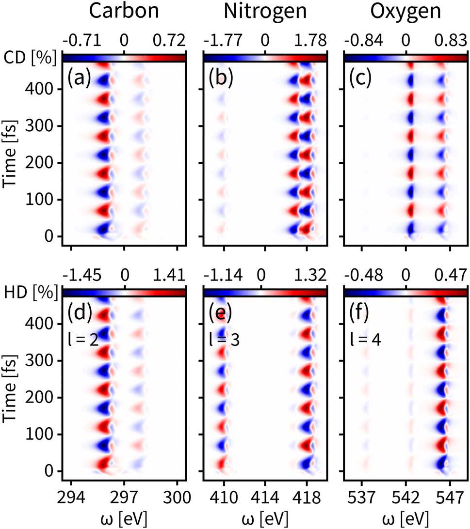 | ||
| Fig. 3 Time-resolved signals of eqn (7) contributed by K-edges of carbon, nitrogen, and oxygen on the ground state S0. (a–c) Simulated tr-CD results. (d–f) Simulated tr-HD results for maximum enantiomer response intensity of the corresponding elements. | ||
The enantiomer dynamics on S1 are shown in Fig. 4. Similar to the ground state, the time-resolved dichroism signals show up as vertical features for different core-to-valence transitions, whose oscillations are consistent with the enantiomer exchange on S1. The more dispersed broadening of the vertical patterns comes from the more diffuse enantiomer distribution during the dynamics as shown in the top panel of Fig. 2(d). The tr-CD signals on S1 are shown in Fig. 4(a–c). The enantiomer response intensity of tr-CD is obviously weaker than that of S0, and the maximum tr-CD signal intensity on S1 occurs on nitrogen reaching from −0.25% to 0.46%. Similarly, by varying the helical indices from l = 1 to 4, the tr-HD technique can improve the enantiomer response intensity and the maximum enhancement of dichroism occurs on carbon with l = 2 reaching from −0.47% to 0.78%, which is already higher than the tr-CD signal. Our simulations demonstrate that tr-HD is superior compared to tr-CD when probing the enantiomer dynamics of formamide in the excited state, which is contrary to the ground state. Interestingly, the tr-HD signals always show maximum strength for carbon, which implies that the atom closer to the light central axis can better feel the handedness of the structural beam itself. As the enantiomer population difference on S1 is much smaller than that on S0 (as shown in Fig. 2(d)), our simulations imply that the tr-HD technique has the potential ability to detect slightly non-chiral molecules.
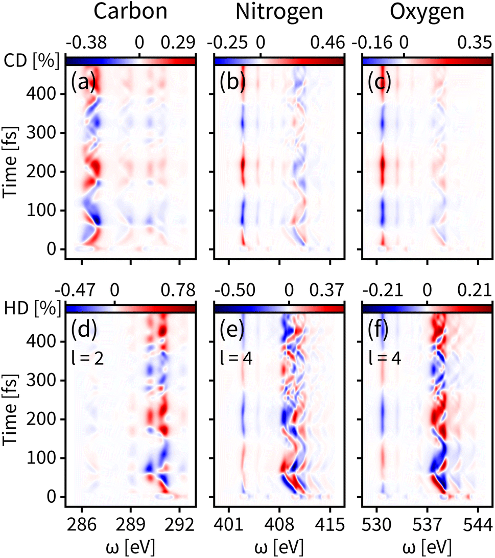 | ||
| Fig. 4 Same as Fig. 3 but for the valence excited state S1. (a–c) Simulated tr-CD results. (d–f) Simulated tr-HD results for maximum enantiomer response intensity of the corresponding elements. | ||
We find that the CD and HD signals have a different sensitivity to the S0 and S1 PESs. For S0, the PES exhibits a parabolic shape centered at the Franck–Condon point, which leads to an easy conversion of the left and right enantiomers. For S1, in contrast, the potential energy curve has a double-well, making the Franck–Condon point at a barrier, thus limiting the exchange of left and right enantiomers. The barrier on the potential energy curve strongly affects the enantiomer kinetics. In addition, the HD signal depends on overlapping spatial integrals between the incoming OAM of light and the spatial distribution of the transition current densities involved. Each transition current can interact more or less efficiently with a given OAM, making the OAM more sensitive to different PESs.
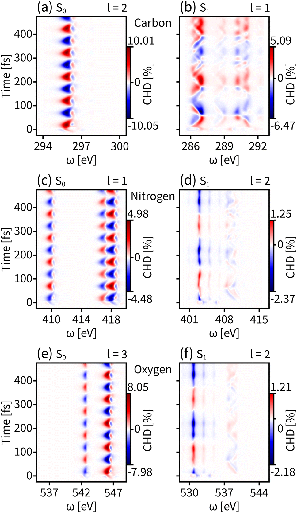
We have discussed the use of tr-CD and tr-HD for the enantiomer dynamics in the ground state S0 and the valence excited state S1. However the magnitudes of dichroism for reflecting the enantiomer response intensity are still weak, especially for S1, where the enhanced results of the HD technique do not exceed 1%. We then combine OAM light with circular polarization and the resulting tr-CHD signals are shown in Fig. 5. The tr-CHD probe can also reflect the enantiomer oscillation periods both on S0 and S1. Furthermore, according to eqn (6), the CHD signal can be regarded as a superposition of two perpendicularly transverse HD signals, which greatly enhances the enantiomer response intensity both for S0 and S1. As shown in the left panels of Fig. 5, the tr-CHD technique enhances the enantiomer response intensity of S0 for probing all elemental K-edges compared to the tr-CD results. In particular, the dichroism magnitude contributed by carbon with l = 2 increases the maximum enantiomer response intensity by more than 10%. As shown in the right panels of Fig. 5, a similar enhancement also applies for the S1 enantiomer dynamics. Compared to tr-HD, the enantiomer response intensities of the tr-CHD technique are more than 2%, and the maximum tr-CHD signal occurs on carbon with l = 1 reaching from −6.47% to 5.09%. Our simulations show that tr-CHD can effectively probe the enantiomer dynamics on various PESs with an order of magnitude enhancement, further illustrating that structured OAM light has great advantages in chiral-related probes.
 | ||
| Fig. 5 Simulated tr-CHD signals for the ground state S0 (left panels) and the valence excited state S1 (right panels) for carbon (a and b), nitrogen (c and d), and oxygen (e and f) K-edges. The shown l values are selected for the maximum enantiomer response intensity. | ||
4 Conclusions
We have proposed a novel tr-HD technique which targets ultrafast chiral dynamics. It demonstrates how X-rays OAM may be used to monitor enantiomeric excess in the time domain and on different PESs. Implementing these time-resolved measurements requires X-ray OAM pulses to probe core-to-valence transitions for a selected element. Resonant X-ray techniques are highly sensitive to the molecular structure. While tr-HD is still dominated by a magnetic dipole–electric dipole transition for point-like molecules near the beam phase singularity, the extra control over beam vorticity allows the asymmetry ratio to be optimized. The chiral discrimination originates from the longitudinal components of the probe beam. The SAM of light adds extra terms to the pseudo-scalar field tensor that can further increase the computed asymmetry in tr-CHD. Molecules on the outskirts of the vortex beam experience a smaller phase gradient and thus small longitudinal beam components, which contribute to the achiral background. This highlights how important it is for tr-HD to achieve high level focusing to maximize the chiral sensitivity of the signal, even when the molecule is much smaller that the beam waist.In this work, we have considered a distribution of molecules located near the propagation axis of an OAM beam where the beam vorticities (and longitudinal components) are maximum. This explains why the computed asymmetry ratio is much larger than the one typically observed for CD signals. This corresponds to a favorable scenario that does not involve molecules that could be located away from the propagation axis. If an experimental setup would involve a bulk liquid phase of chiral molecules, molecules located on the outskirts of the beam would also significantly contribute from regions where the beam chirality is less important. These molecules would contribute more strongly to an achiral background and reduce the observed asymmetry ratio. So far, experimental data are lacking to evaluate how strong this effect is, and it would depend on the OAM and the molecule used in the experiment. These considerations highlight that probing molecular chirality with an OAM becomes advantageous with respect to the use of circular polarization only when very tight focuses can be achieved, for example, when using X-rays.
In formamide, three X-ray chromophores, C, N and O, are used to explore which element gives the largest asymmetry ratio. An asymmetric pumping is implemented by using left circularly polarized actinic beams. The chiral dynamics is measured by the tr-HD and tr-CHD techniques using linearly and circularly polarized light, respectively, and compared with that by the common tr-CD technique. Our simulations reveal that the tr-CD signal is more sensitive to ground state enantiomer dynamics, while the tr-HD signal is preferred for probing enantiomeric oscillations in the valence excited state. The tr-HD technique achieves higher sensitivity for smaller enantiomer differences by tuning the OAM value of the probe beams. More importantly, tr-CHD has a much stronger signature of chiral dynamics on both the PESs of the ground and the excited state, which reflects the advantage of OAM light in studies of chirality. Synchrotrons or free electron lasers can generate high-quality X-ray OAM beams with a tight waist, fine resolution, and high intensity, making them suitable for the proposed applications.
Data availability
All study data are included in the article and/or ESI.†Author contributions
S. M. supervised the project. J. R. R. and H. Y. conceived the project. J. R. R. and X. J. derived the formulae of the signal. Y. N. performed the wavepacket dynamics calculations. X. J. performed the electronic structure calculations and the signal simulations. All authors contributed to the analysis and interpretation of the results, and wrote the manuscript.Conflicts of interest
There are no conflicts to declare.Acknowledgements
The support of the U.S. Department of Energy, Office of Science, Office of Basic Energy Sciences under award DE-FG02-04ER15571 to H. Y. and J. R. R. is gratefully acknowledged. S. M. acknowledges the support of the National Science Foundation through grant no. CHE-2246379. S. M. is a fellow of the Hagler Institute of advanced study at Texas A&M University.Notes and references
- W. H. Brooks, W. C. Guida and K. G. Daniel, Curr. Top. Med. Chem., 2011, 11, 760–770 CrossRef CAS PubMed.
- N. Koga, R. Tatsumi-Koga, G. Liu, R. Xiao, T. B. Acton, G. T. Montelione and D. Baker, Nature, 2012, 491, 222–227 CrossRef CAS PubMed.
- M. Liu, L. Zhang and T. Wang, Chem. Rev., 2015, 115, 7304–7397 CrossRef CAS PubMed.
- M. Rickhaus, M. Mayor and M. Juríček, Chem. Soc. Rev., 2016, 45, 1542–1556 RSC.
- R. Naaman, Y. Paltiel and D. H. Waldeck, Nat. Rev. Chem, 2019, 3, 250–260 CrossRef CAS.
- H. C. Aspinall, Chem. Rev., 2002, 102, 1807–1850 CrossRef CAS PubMed.
- E. Francotte, W. Lindner, R. Mannhold, H. Kubinyi and G. Folkers, Chirality in drug research, Wiley-VCH, Weinheim, 2006, vol. 33 Search PubMed.
- U. Banin, A. Bartana, S. Ruhman and R. Kosloff, J. Chem. Phys., 1994, 101, 8461–8481 CrossRef CAS.
- S. Mukamel, A. Piryatinski and V. Chernyak, Acc. Chem. Res., 1999, 32, 145–154 CrossRef CAS.
- N. Rohringer, Philos. Trans. R. Soc., A, 2019, 377, 20170471 CrossRef CAS PubMed.
- H. Kuramochi and T. Tahara, J. Am. Chem. Soc., 2021, 143, 9699–9717 CrossRef CAS PubMed.
- P. J. Ho, G. Doumy and L. Young, in X-ray Free-Electron Lasers: A New Tool for Atomic, Molecular and Chemical Dynamics, American Chemical Society, 2021, vol. 1398, pp. 15–48 Search PubMed.
- Y. Lee, H. Lee and H. Ihee, Chem. Phys. Rev., 2022, 3, 041304 CrossRef CAS.
- D. Keefer, S. M. Cavaletto, J. R. Rouxel, M. Garavelli, H. Yong and S. Mukamel, Annu. Rev. Phys. Chem., 2023, 74, 73–97 CrossRef PubMed.
- A. Odate, A. Kirrander, P. M. Weber and M. P. Minitti, Adv. Phys.: X, 2023, 8, 2126796 Search PubMed.
- N. Berova, K. Nakanishi and R. W. Woody, Circular dichroism: principles and applications, John Wiley & Sons, 2000 Search PubMed.
- S. M. Kelly, T. J. Jess and N. C. Price, Biochim. Biophys. Acta, Proteins Proteomics, 2005, 1751, 119–139 CrossRef CAS PubMed.
- D. Baykusheva, D. Zindel, V. Svoboda, E. Bommeli, M. Ochsner, A. Tehlar and H. J. Wörner, Proc. Natl. Acad. Sci. U. S. A., 2019, 116, 23923–23929 CrossRef CAS PubMed.
- M. Oppermann, B. Bauer, T. Rossi, F. Zinna, J. Helbing, J. Lacour and M. Chergui, Optica, 2019, 6, 56–60 CrossRef CAS.
- Y. Zhang, J. R. Rouxel, J. Autschbach, N. Govind and S. Mukamel, Chem. Sci., 2017, 8, 5969–5978 RSC.
- J. R. Rouxel, Y. Zhang and S. Mukamel, Chem. Sci., 2019, 10, 898–908 RSC.
- S. F. Mason and S. F. Mason, Molecular optical activity and the chiral discriminations, Cambridge University Press, 1982 Search PubMed.
- Y. Tang and A. E. Cohen, Science, 2011, 332, 333–336 CrossRef CAS PubMed.
- B. Ritchie, Phys. Rev. A: At., Mol., Opt. Phys., 1976, 13, 1411–1415 CrossRef.
- N. Böwering, T. Lischke, B. Schmidtke, N. Müller, T. Khalil and U. Heinzmann, Phys. Rev. Lett., 2001, 86, 1187–1190 CrossRef PubMed.
- A. Comby, S. Beaulieu, M. Boggio-Pasqua, D. Descamps, F. Légaré, L. Nahon, S. Petit, B. Pons, B. Fabre, Y. Mairesse and V. Blanchet, J. Phys. Chem. Lett., 2016, 7, 4514–4519 CrossRef CAS PubMed.
- V. Svoboda, N. B. Ram, D. Baykusheva, D. Zindel, M. D. J. Waters, B. Spenger, M. Ochsner, H. Herburger, J. Stohner and H. J. Wörner, Sci. Adv., 2022, 8, eabq2811 CrossRef CAS PubMed.
- P. V. Demekhin, A. N. Artemyev, A. Kastner and T. Baumert, Phys. Rev. Lett., 2018, 121, 253201 CrossRef CAS PubMed.
- S. Beaulieu, A. Comby, D. Descamps, B. Fabre, G. A. Garcia, R. Géneaux, A. G. Harvey, F. Légaré, Z. Mašín, L. Nahon, A. F. Ordonez, S. Petit, B. Pons, Y. Mairesse, O. Smirnova and V. Blanchet, Nat. Phys., 2018, 14, 484–489 Search PubMed.
- D. Ayuso, O. Neufeld, A. F. Ordonez, P. Decleva, G. Lerner, O. Cohen, M. Ivanov and O. Smirnova, Nat. Photonics, 2019, 13, 866–871 CrossRef CAS.
- S. M. Barnett and L. Allen, Opt. Commun., 1994, 110, 670–678 CrossRef.
- C. Hernández-García, Nat. Phys., 2017, 13, 327–329 Search PubMed.
- G. F. Quinteiro and P. I. Tamborenea, Europhys. Lett., 2009, 85, 47001 CrossRef.
- L. Allen, M. W. Beijersbergen, R. J. C. Spreeuw and J. P. Woerdman, Phys. Rev. A: At., Mol., Opt. Phys., 1992, 45, 8185–8189 CrossRef PubMed.
- D. Lee, H. Sasaki, H. Fukumoto, K. Hiraga and T. Nakagawa, IEICE Trans. Commun., 2017, E100.B, 1044–1063 CrossRef.
- D. G. Grier, Nature, 2003, 424, 810–816 CrossRef CAS PubMed.
- X.-L. Wang, J. Chen, Y. Li, J. Ding, C.-S. Guo and H.-T. Wang, Phys. Rev. Lett., 2010, 105, 253602 CrossRef PubMed.
- A. Mair, A. Vaziri, G. Weihs and A. Zeilinger, Nature, 2001, 412, 313–316 CrossRef CAS PubMed.
- J. Leach, B. Jack, J. Romero, A. K. Jha, A. M. Yao, S. Franke-Arnold, D. G. Ireland, R. W. Boyd, S. M. Barnett and M. J. Padgett, Science, 2010, 329, 662–665 CrossRef CAS PubMed.
- H. Yong, J. R. Rouxel, D. Keefer and S. Mukamel, Phys. Rev. Lett., 2022, 129, 103001 CrossRef CAS PubMed.
- K. A. Forbes, D. Green and G. A. Jones, J. Opt., 2021, 23, 075401 CrossRef CAS.
- L. Ye, J. R. Rouxel, S. Asban, B. Rösner and S. Mukamel, J. Chem. Theory Comput., 2019, 15, 4180–4186 CrossRef CAS PubMed.
- W. Brullot, M. K. Vanbel, T. Swusten and T. Verbiest, Sci. Adv., 2016, 2, e1501349 CrossRef PubMed.
- J. R. Rouxel, B. Rösner, D. Karpov, C. Bacellar, G. F. Mancini, F. Zinna, D. Kinschel, O. Cannelli, M. Oppermann and C. Svetina, et al. , Nat. Photonics, 2022, 16, 570–574 CrossRef CAS.
- R. M. Kerber, J. M. Fitzgerald, S. S. Oh, D. E. Reiter and O. Hess, Commun. Phys., 2018, 1, 87 CrossRef.
- J. Als-Nielsen and D. McMorrow, Elements of modern X-ray physics, John Wiley & Sons, 2011 Search PubMed.
- Y. Nam, D. Cho, B. Gu, J. R. Rouxel, D. Keefer, N. Govind and S. Mukamel, J. Am. Chem. Soc., 2022, 144, 20400–20410 CrossRef CAS PubMed.
- J. C. T. Lee, S. J. Alexander, S. D. Kevan, S. Roy and B. J. McMorran, Nat. Photonics, 2019, 13, 205–209 CrossRef CAS.
- L. Novotny and N. van Hulst, Nat. Photonics, 2011, 5, 83–90 CrossRef CAS.
- E. Hemsing and A. Marinelli, Phys. Rev. Lett., 2012, 109, 224801 CrossRef CAS PubMed.
- S. Tanaka, V. Chernyak and S. Mukamel, Phys. Rev. A: At., Mol., Opt. Phys., 2001, 63, 063405 CrossRef.
- J. R. Rouxel, V. Y. Chernyak and S. Mukamel, Chem. Sci., 2016, 7, 6824–6831 RSC.
- J. Campbell and T. Papp, Atomic Data Nucl. Data Tables, 2001, 77, 1–56 CrossRef CAS.
- G. F. Quinteiro, F. Schmidt-Kaler and C. T. Schmiegelow, Phys. Rev. Lett., 2017, 119, 253203 CrossRef CAS PubMed.
- I. Ishii and A. P. Hitchcock, J. Chem. Phys., 1987, 87, 830–839 CrossRef CAS.
- H.-J. Werner, P. J. Knowles, F. R. Manby, J. A. Black, K. Doll, A. Heßelmann, D. Kats, A. Köhn, T. Korona, D. A. Kreplin, Q. Ma, T. F. Miller III, A. Mitrushchenkov, K. A. Peterson, I. Polyak, G. Rauhut and M. Sibaev, J. Chem. Phys., 2020, 152, 144107 CrossRef CAS PubMed.
- B. O. Roos, P. R. Taylor and P. E. Sigbahn, Chem. Phys., 1980, 48, 157–173 CrossRef CAS.
- P. A. Malmqvist, A. Rendell and B. O. Roos, J. Phys. Chem., 1990, 94, 5477–5482 CrossRef CAS.
- H. A. Elion and D. Stewart, Progress in Nuclear Energy, Series IX: Analytical Chemistry, Pergamon Press, Oxford, 1969, vol. 9 Search PubMed.
- J. R. Rouxel, M. Kowalewski and S. Mukamel, Struct. Dyn., 2017, 4, 044006 CrossRef PubMed.
Footnote |
| † Electronic supplementary information (ESI) available: Time-resolved enantiomer-exchange probed by using the orbital angular momentum of X-ray light. See DOI: https://doi.org/10.1039/d3sc02807k |
| This journal is © The Royal Society of Chemistry 2023 |