
Theoretical exploration of the nitrogen fixation mechanism of two-dimensional dual-metal TM1TM2@C9N4 electrocatalysts†
Jinxin
Sun‡
a,
Peng
Xia‡
a,
Yuxing
Lin‡
a,
Yunfan
Zhang
a,
Anjie
Chen
a,
Li
Shi
b,
Yongjun
Liu
a,
Xianghong
Niu
 *c,
Ailei
He
*a and
Xiuyun
Zhang
*a
*c,
Ailei
He
*a and
Xiuyun
Zhang
*a
aCollege of Physics Science and Technology, Yangzhou University, Yangzhou 225002, China. E-mail: heailei@yzu.edu.cn; xyzhang@yzu.edu.cn
bState Key Laboratory of Organic Electronics and Information Displays & Institute of Advanced Materials (IAM), Jiangsu National Synergetic Innovation Center for Advanced Materials (SICAM), School of Materials Science and Engineering, Nanjing University of Posts and Telecommunications, Nanjing 210023, China
cNew Energy Technology Engineering Laboratory of Jiangsu Province & School of Science, Nanjing University of Posts and Telecommunications, Nanjing, 210023, China. E-mail: xhniu@njupt.edu.cn
First published on 29th November 2022
Abstract
The electrochemical nitrogen reduction reaction (eNRR) to NH3 has become an alternative to traditional NH3 production techniques, while developing NRR catalysts with high activity and high selectivity is of great importance. In this study, we systematically investigated the potentiality of dual transition metal (TM) atom anchored electrocatalysts, TM1TM2@C9N4 (TM1, TM2 = 3(4)d TM atoms), for the NRR through the first principles high-throughput screening method. A total of 78 TM1TM2@C9N4 candidates were designed to evaluate their stability, catalytic activity, and selectivity for the NRR. Four TM1TM2@C9N4 candidates (TM1TM2 = NiRu, FeNi, TiNi, and NiZr) with an end-on N2 adsorption configuration, and two candidates (TM1TM2 = TiNi and TiFe) with a side-on adsorption configuration, were screened out with the advantage of suppressing the hydrogen evolution reaction (HER) and exhibiting high NRR activity. Moreover, the catalysts with end-on and side-on N2 adsorption configurations were determined to favor distal and consecutive reaction pathways, respectively, with favorable limiting potentials of only −0.33 V to −0.53 V. Detailed analysis showed that the N2 adsorption and activation are primarily ascribed to the strong back-donation interactions between the d-electrons of TM atoms and the anti-orbitals of an N2 molecule. Our findings pave a way for the rational design and rapid screening of highly active C9N4-based catalysts for the NRR.
New conceptsInspired by the synergistic effect of multi-active centers in dual-atom catalysts (DACs) or few-atom catalysts (FACs), we proposed to explore the nitrogen reduction reaction (NRR) performance of TM1TM2@C9N4 (TM = 3(4)d transition metal atoms) electrocatalysts by a high-throughput screening method. Compared with many SACs and DACs, the screened dual-metal atom TM1TM2@C9N4 candidates are found to display ultra-high stabilities, high NRR activity, and ability to effectively suppress the hydrogen evolution reaction (HER). The superior activity of these TM1TM2@C9N4s can primarily be ascribed to the strong back-donation interactions between the d-electrons of TM atoms and the anti-orbitals of a N2 molecule and other nitrogen intermediates. This study paves a way for the rational design and rapid screening of highly active C9N4-based catalysts for the NRR. |
1. Introduction
Currently, the electrochemical nitrogen reduction reaction (eNRR) to ammonia (NH3) is attracting more attention due to its mild conditions with attractive features of low cost and sustainable development,1–3 and is regarded as one promising way to break the barrier of industrial NH3 synthesis under harsh conditions. During the eNRR, the use of suitable catalysts is crucial, because the inertness of N2 leads to the difficulty of its adsorption and activation, leading to a low reaction efficiency.4–6 In addition, the N2 reduction process is seriously suppressed by the accompanying hydrogen evolution reaction (HER).7–9 Therefore, designing or fabricating NRR catalysts with high activity and high selectivity is one great challenge for researchers.To date, various electrocatalysts for the NRR have been developed and explored by experimental and theoretical researchers.10–13 Among them, the single-metal atom catalysts (SACs) or few-metal atom catalysts (FACs), in which single or few metal atoms are well adsorbed on suitable substrates, are becoming one promising type of candidates for the eNRR and other electrochemical reactions due to their advantage of precisely controlling the rate-determining or other reaction steps.14–17 For example, Zeng et al. synthesized a N-doped carbon monolayer with Ru atoms anchored, which achieved a record-high faradaic efficiency (FE) of 29.6% and a yield rate of 120.9 μgNH3 h−1 magcat−1.18 Li et al. reported that the SAC of Mo atoms atomically distributed graphdiyne and has a high FE of over 21% and a yield rate of 145.4 μgNH3 h−1 magcat−1.19 However, the key challenge in designing outstanding SACs or FACs is the choice of supporting substrates, which play an important role in anchoring and transferring charges to metal atoms. Interestingly, various 2D materials, e.g., graphene,20 transition metal dichalcogenides (TMDs),21,22 hexagonal BN,23etc., have been widely used as supports for SACs or FACs. Particularly, B or N atom doped 2D materials are confirmed to be good at binding and enhancing the catalytic activity of metal atoms.24–26 Through density functional theory calculations, Le et al. revealed that SACs obtained by Mo anchoring on N-doped graphene can achieve 100% selectivity for N2 fixation.27 Similarly, Zhao et al. found that “CrN3” doped graphene possesses excellent catalytic performance for N2 reduction.28 Interestingly, Jiao et al. revealed that the NRR activity of the Fe atom in Fe–N–C SACs can be greatly improved by coordinating with a B dopant,29 in which the limiting potential (UL) of the NRR on Fe–B2N2 is −0.65 V. Besides, Ou et al. found a highly active NRR catalyst by embedding isolated Mo atoms on N-doped black phosphorous,30 with UL of −0.56 V.
In addition to SACs, the FACs possessing two or more active metal centers31,32 were also revealed to be potential NRR catalysts due to their synergistic effects in adjusting the adsorption configuration of NRR reactive species and reducing the energy barrier in the reaction process. For example, Luo et al. reported that the FeMo dual atomic cluster embedded on N-doped carbon shows an FE of 41.7% at 0.2 V for the NRR, much smaller than those of its SAC counterparts (FeN4 and MoN4).33 Deng ET AL. systematically studied the NRR reactivity of homo dual atomic catalysts formed by 20 transition metal (TM) elements supported by N-doped graphene and screened out Ru2N6@G as an excellent catalyst.34 Zheng et al. theoretically designed hetero dual-metal Fe/M–N–C catalysts and revealed the synergistic effect of Fe/M dual-metal active sites by theoretical calculations.35 Very recently, Zheng et al. systematically investigated the catalytic performance of various triple-TM clusters anchored on nitrogen-doped graphene for the NRR and confirmed that Co3–N4@G possesses the highest activity with a limiting potential of −0.41 V through the enzymatic mechanism.36 Moreover, Li and co-workers revealed that Ru3–N4@G with three Ru trimer clusters anchored on N-doped carbon (Ru3–N4) have better 2-amino-benzaldehyde catalytic activity than the SAC counterpart of RuN4.37
Furthermore, many pristine 2D CxNy systems, such as g-C3N4, g-C2N, and g-CN, have received extensive attention in many catalysis fields due to their large surface area, high stability, rich coordination environments, etc.16,38,39 As a member of the CxNy family, C9N4 possesses semimetallic properties, high thermodynamic stability, and numerous nanopores favorable for TM loading.40 For example, Zhou et al. theoretically designed Ni@C9N4 bifunctional electrocatalysts for efficient water splitting.41 Chen et al. screened TM@C9N4 (TM = 3d, 4d, and 5d TM atoms) candidates for potential NRR catalysts by high-throughput computation, and found that the optimal catalyst W@C9N4 favors the distal mechanism with a confinement potential of −0.24 V.42 However, the work of anchoring homo-/hetero-nuclear transition metal atoms on C9N4 to obtain excellent NRR catalysts has not been addressed.
In this work, we systematically explored the NRR performance of bimetal catalysts, TM1TM2@C9N4 (TM1TM2 = 3d, 4d TM atoms), by first principles high-throughput calculations. A total of 78 TM1TM2@C9N4 candidates, including 12 homo dual TM based systems and 66 hetero dual TM based systems, are considered. After the six-step screening, we obtained five high activity TM1TM2@C9N4 catalysts with high stability and high selectivity.
2. Computational methods and modeling
All the calculations were carried out using the projector augmented wave (PAW) method as implemented in the Vienna ab initio simulation package (VASP).43,44 The exchange–correlation interaction was treated using the generalized gradient approximation (GGA) parameterized by Perdew,45 Burke and Ernzerhof (PBE).46,47 A vacuum space of 18 Å was inserted in the z-direction of the 2 × 2 × 1 C9N4 supercell to eliminate the interaction between adjacent periodic units. 3 × 3 × 1 Monkhorst–Pack k-point meshes were applied to sample the first Brillouin zone, while denser k-points of 7 × 7 × 1 were applied for electronic structure calculations. In structural relaxation, the total energy and the force on each relaxed atom were converged to 10−5 eV and 0.01 eV Å−1. Spin polarization is considered, and the energy cutoff for the plane-wave basis set was 450 eV. Ab initio molecular dynamics (AIMD) simulations were applied to identify the thermodynamic stability of TM1TM2@C9N4 candidates.48 In the electrochemical process of the NRR, six proton and electron transfer steps, e.g., N2 + 6H+ + 6e− → 2NH3, are evolved. To efficiently evaluate the NRR activity of all the TM1TM2@C9N4 candidates, the reaction free energy (ΔG) for each fundamental step was calculated according to the computational hydrogen electrode (CHE) model.49,50 In this framework, the chemical potential of the proton–electron pair (H+ + e−) can be referenced to one half of that of H2 under standard reaction conditions, and the change in the reaction free energy for each step can be evaluated as:| ΔG = ΔE + ΔZPE − TΔS + eU + ΔGpH | (1) |
![[thin space (1/6-em)]](https://www.rsc.org/images/entities/char_2009.gif) 10, and the pH value is assumed to be 0.
10, and the pH value is assumed to be 0.
3. Results and discussion
3.1. Structures and stability of TM1TM2@C9N4
First, we investigated the structures and stabilities of these TM1TM2@C9N4 catalysts. As shown in Fig. 1a and b, the selected substrate is a 2 × 2 C9N4 supercell containing 72 carbon atoms and 32 nitrogen atoms. Here, eight of the 3d TM atoms (e.g., Ti, V, Cr, Mn, Fe, Co, Ni, and Cu) and four of the 4d TM atoms (e.g., Zr, Mo, Tc, and Ru) were taken into consideration. As a result, 78 dual-metal TM1TM2@C9N4 catalysts were constructed, including 12 homonuclear and 66 heteronuclear systems. Besides, three types of anchoring sites (S1, S2, and S3) were tested: (i) S1 configuration, two TM atoms sit in a horizontal line with each atom binding to three adjacent N atoms (see Fig. 1a), (ii) S2 configuration, the TM–TM bond of the S1 configuration was anticlockwise rotated by 30 degree (see Fig. 1b), in which each TM atom only bonds with two nearest N atoms, and (iii) S3 configuration, two TM atoms from the systems are no longer coordinated equally, and bind with two and three adjacent N atoms, respectively (see Fig. 1c). All the optimized structures are shown in Fig. S1–S4 in the ESI.† Clearly, no significant structural deformation is found for all the studied TM1TM2@C9N4 systems. For TM1TM2@C9N4 anchored with homonuclear dual-metal atoms (TM1 = TM2, see Fig. S1, ESI†), the S1 configuration is favored for those with smaller diameters, e.g., Fe, Co, and Ni, and the S2 configuration is preferred for the candidates having larger diameters, e.g., Ti–Mn, Cu, Zr, and Ru. Similarly, for TM1TM2@C9N4 combined with hetero TM atoms (TM1 ≠ TM2), the S1 configuration is observed for those with close to TM diameters (see Fig. S2, ESI†), and the S2 one is found for those with larger TM diameters (see Fig. S3, ESI†). And for the systems with large diameter differences for two TM atoms, taking CuTM@C9N4s (TM = Ti, V, Cr, Mn, Fe, Ru, Mo, and Tc) as an example, the Cu atom with a large atomic diameter favors the S2 bonding style, while the other TM atoms with smaller diameters favor the S3 bonding style. As the Cu atom sits out of the CuZr@C9N4 plane, it is unsuitable to form a dual catalytic center site for nitrogen adsorption. The TM1–TM2 bond lengths (dTM1–TM2) of the remaining systems are around 1.484–2.376 Å, which are smaller than those in their metal bulk (see Fig. 1e). Among which, Mn2@C9N4 has the shortest dTM1–TM2 (= 1.484 Å), while TiCu@C9N4 has the longest dTM1–TM2 (= 2.376 Å).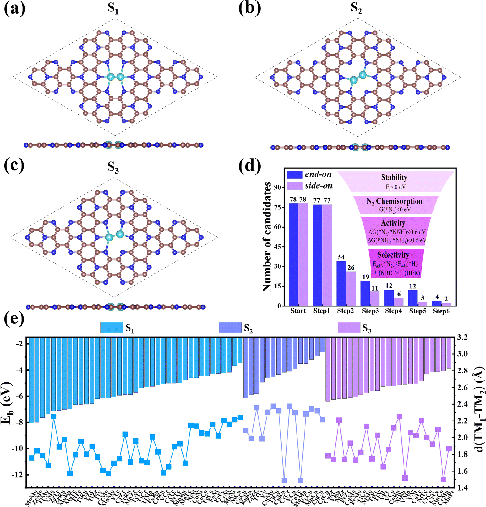 | ||
| Fig. 1 Top and side views of (a) S1-, (b) S2- and (c) S3-configuration TM1TM2@C9N4. (d) Schematic illustration of the screening results by the “six-step” strategy. (e) Binding energies of dual TM atoms (TM1 and TM2) (Eb) and TM1–TM2 bond length (dTM1–TM2) of the 78 TM1TM2@C9N4 catalysts. The brown, navy blue and light blue balls represent C, N, and TM atoms, respectively. | ||
To explore the stability of these TM1TM2@C9N4 systems, we calculated their binding energies (Eb) per TM atom using the following equation:
 | (2) |
3.2. N2 adsorption and activation of TM1TM2@C9N4
Then, we systematically explored the adsorption of N2, which is the prerequisite for the subsequent hydrogenation process in the NRR. Generally, two forms of N2 adsorption on catalysts, end-on and side-on configurations, are considered. In the two dual-metal atom doped systems, we investigated six possible adsorption ways, including two end-on adsorption configurations (E-1 and E-2, see Fig. 2a and b) and four side-on adsorption configurations (S-1, S-2, S-3, and S-4, see Fig. 2c–f). For the E-1 configuration, the end N atom from N2 sits atop one TM atom (see Fig. 2a), while for the E-2 configuration, the end N atom from N2 resides on the bridge site of two TM atoms (see Fig. 2b). As for S configurations, the N2 plane is parallel with the C9N4 substrate. Of these, the S-1 and S-4 configurations have structures with the N![[triple bond, length as m-dash]](https://www.rsc.org/images/entities/char_e002.gif) N bond perpendicular to the TM–TM bond (see Fig. 2c and f), while for S-2 and S-3 configurations, the NN bond is found to be parallel to the TM–TM bond (see Fig. 2d and e).
N bond perpendicular to the TM–TM bond (see Fig. 2c and f), while for S-2 and S-3 configurations, the NN bond is found to be parallel to the TM–TM bond (see Fig. 2d and e).
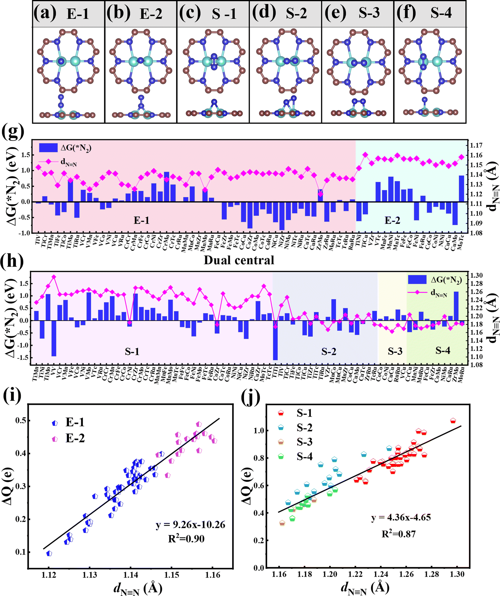 | ||
| Fig. 2 The considered adsorption configurations of (a and b) end-on (E-1, E-2) and (c–f) side-on (S-1, S-2, S-3, and S-4) for N2 on the TM1TM2@C9N4 substrate. Gibbs free energy change G(*N2) values and NN bond lengths of *N2 (dNN) adsorbed on 77 TM1TM2@C9N4 catalysts with (g) end-on and (h) side-on adsorption configurations. Relationships between charge transfer (ΔQ) and dNN adsorbed on 77 TM1TM2@C9N4 catalysts through (i) end-on and (j) side-on adsorption configurations. | ||
In order to ensure the effective adsorption of N2, the Gibbs free energy of N2, ΔG(*N2) < 0 eV, is set as the second screening criterion, and the catalysts that could effectively adsorb N2 in two adsorption configurations are selected. The ΔG(*N2) values of 77 TM1TM2@C9N4 with end-on and side-on bonding characters are described in Fig. 2g and h, respectively. It is observed that ΔG(*N2) values on 34 TM1TM2@C9N4 with end-on adsorption for N2 are negative, ranging from −0.001 to −0.91 eV. Besides, 26 candidates with side-on adsorption for N2 are confirmed to have negative ΔG(*N2), around −0.03 to −1.60 eV. Among which, 17 systems display negative ΔG(*N2) in both adsorption configurations, ranging from −0.03 to −0.85 eV. Except TiNi@C9N4, TiCu@C9N4, and FeNi@C9N4, the ΔG(*N2) values of all the other TM1TM2@C9N4 candidates with end-on adsorption patterns are more negative than those of side-on configurations, indicating that they are more energetically favorable. It is noted that most candidates containing Cr or Mn atoms (20 systems) are not conducive to the adsorption of N2; exceptions are found for CrNi@C9N4, CrCu@C9N4, and MnCu@C9N4 candidates with side-on adsorption configurations. The inertness of these candidates can be ascribed to the stable half occupied electronic structures of Cr(3d54s1) or Mn(3d54s2). As for the systems containing 4d TM (= Zr, Mo, Tc, and Ru) atoms, end on adsorption of N2 is favored, with an exception of TiZr@C9N4.
The NN bond lengths (dNN) of the adsorbed N2 molecule on these TM1TM2@C9N4 candidates are summarized in Fig. 2g and h. Compared with the free N2 molecule (1.12 Å), the NN bond lengths for *N2 were elongated, indicating the effective activation of the N2 molecule. For the end-on adsorbed systems, the dNN values (= 1.147Å–1.160 Å) of the E-2 adsorption configurations are longer than those of the E-1 ones (dNN = 1.120–1.148 Å) (see Fig. 2g). However, for the side-on adsorbed systems, the dNN of *N2 is much longer, around 1.162–1.279 Å, indicating that the N2 molecule is more pronouncedly activated. Moreover, the dNN of the systems with the S-1 adsorption configuration (1.221–1.299 Å) is longer than those of the other three adsorption configurations (S-2: 1.167–1.247 Å, S-3: 1.162–1.187 Å, and S-4: 1.169–1.204 Å).
To explain the origin of the activation of N2 on these TM1TM2@C9N4 substrates, the relationships of the NN bond length (dNN) and the charge transfer from the TM1TM2@C9N4 substrate to *N2 (ΔQ) are summarized in Fig. 2g and h. Clearly, the dNN is linearly related to ΔQ from TM1TM2@C9N4 to *N2; that is, the more the charge transfer, the longer the N≡N bond length. Compared with the systems with end-on configurations (ΔQ = 0.096–0.489 e), more charge transfer is found for the ones with side-on configurations, e.g., ΔQ = 0.327–1.071 e (see Fig. 2g and h). Accordingly, dNN values of the *N2 in the side-on adsorption systems are longer than those of the end-on ones as discussed above. Also, the significant difference between dNN and ΔQ indicates that TM1TM2@C9N4 systems with side-on configurations for N2 are easier to obtain electrons and activate the NN triple bond. Moreover, the systems with the E-2 adsorption configuration have more charge transfer (ΔQ = 0.333–0.489 e) than those of the E-1 adsorption configuration (ΔQ = 0.096–0.399 e), indicating that the E-2 adsorption configuration is easier to activate N2 than the E-1 ones. The different activation behaviors can be attributed to the direct interaction between the N atoms of the E-2 adsorption configuration and the two TM atoms. As shown in Fig. 2j, the ΔQ of the S-1 adsorption configurations (ΔQ = 0.626–1.071 e) is higher than those of the S-3 (ΔQ = 0.327–0.496 e) and S-4 (ΔQ = 0.359–0.569 e) ones, indicating that the S-1 adsorption configuration is more likely to activate N2, which can be attributed to the direct interaction of both N atoms with TM atoms in the S-1 adsorption configuration. In contrast, the ΔQ of the S-2 adsorption configuration is moderate due to the direct interaction of one N with two TM atoms and the other N with only one TM atom. Based on the above analysis, we considered 34 TM1TM2@C9N4 candidates with the end-on configuration and 26 candidates with the side-on configuration having ΔG(*N2) < 0 eV in the following section (see Fig. 1d).
3.3. The NRR process of TM1TM2@C9N4
As the catalytic efficiency of the NRR is usually limited by the first and last protonation steps,39,42 the free energy change of the first and last hydrogenation steps is set to be less than 0.60 eV, that is ΔG*N2→*NNH < 0.60 eV, ΔG*NH2→*NH3 < 0.60 eV, as the third and fourth step screening criteria.52Fig. 3a and b plot the Gibbs free energy changes of the first (ΔG*N2→*NNH) and last (ΔG*NH2→*NH3) protonation steps of the candidates with end-on and side-on N2 adsorption configurations. As shown in Fig. 3a, 15 candidates with the end-on adsorption configuration like CoRu@C9N4, CuTc@C9N4, etc. are eliminated due to their larger protonation energy of ΔG*N2→*NNH > 0.6 eV, leaving the remaining 19 candidates for potential catalysts. Next, 7 candidates, like VZr@C9N4, TiV@C9N4, etc., are further rejected due to their higher protonation energies in the last step with ΔG*NH2→*NH3 > 0.6 eV. For the side-on adsorption configurations, respective 15 candidates and 5 candidates are rejected due to the higher energies for the first and last protonation steps (see Fig. 3b). As a result, 18 TM1TM2@C9N4 candidates with 12 end-on and 6 side-on adsorption configurations are reserved based on the third and fourth step screening criteria (see Fig. 1d).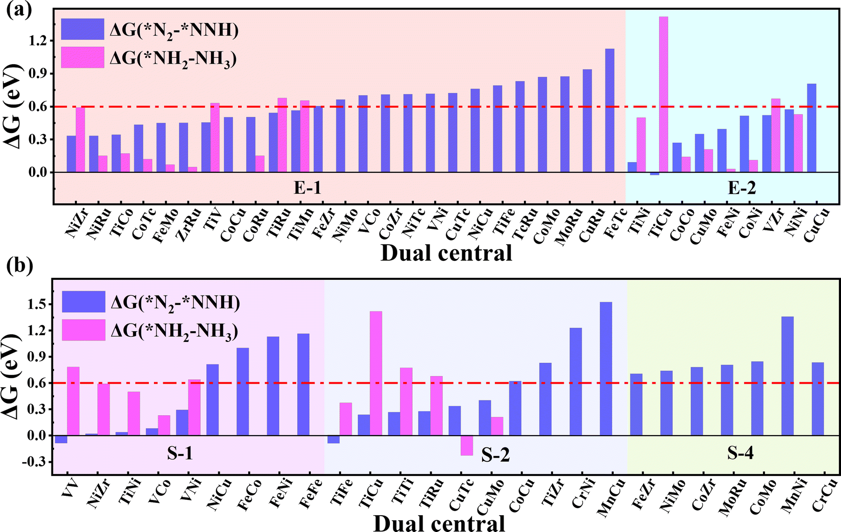 | ||
| Fig. 3 Gibbs free energy change of *N2 + H+ + e− → *NNH (ΔG(*N2–*NNH)) and *NH2 + H+ + e− → *NH3 (ΔG(*NH2–*NH3)) adsorbed on 34 and 26 TM1TM2@C9N4 catalysts through (a) end-on and (b) side-on configurations. | ||
To carefully examine the potential-determining step (PDS) of each catalyst, we further do a full reaction path search for the remaining 18 TM1TM2@C9N4 candidates. For 12 end-on adsorption configurations, 8 TM1TM2@C9N4 candidates (TM1TM2 = NiRu, TiCo, CoTc, FeMo, CoRu, NiTc, NiZr, and CoCo) with E-1 N2 adsorption configurations and 4 TM1TM2@C9N4 candidates (TM1TM2 = FeNi, TiNi, CoNi, and NiNi) with E-2 N2 adsorption configurations are determined. As for 6 side-on adsorption candidates, respective 3 TM1TM2@C9N4 candidates (TM1TM2 = VCo, TiNi, and NiZr) with S-1 adsorption configurations and 3 S-2 candidates (TM1TM2 = CuTc, TiFe, and CuMo) are determined. As shown in Scheme 1, various NRR reaction pathways of different N2 adsorption configurations are discussed. For the candidates with the end-on adsorption configuration, distal and alternating paths are considered, respectively. And for the systems with the side-on adsorption configuration, consecutive and enzymatic paths are considered. For the alternating and enzymatic paths, proton–electron pairs are added alternately to the two N atoms, while for the distal and consecutive paths, the proton–electron pairs continuously attack the same one of two N atoms until the first NH3 is released.
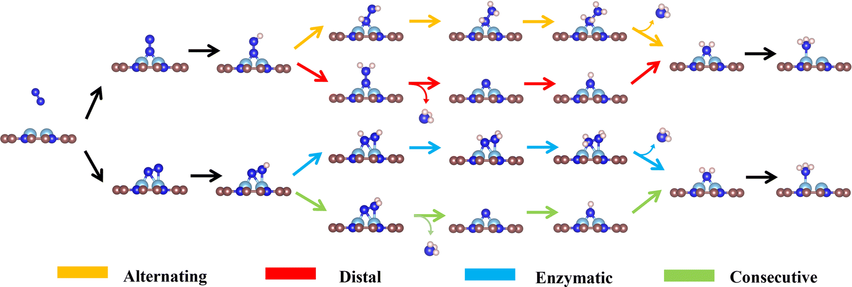 | ||
| Scheme 1 Schematic diagram of possible reaction pathways for the NRR on TM1TM2@C9N4. | ||
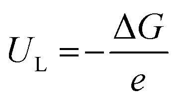
The limiting potential (UL), the lowest negative voltage endows a spontaneous hydrogenation reaction, can also be used to reveal the activity of NRR electrocatalysts. The UL of the NRR can be calculated using the following equation:
 | (3) |
 | ||
| Fig. 4 (a) Theoretical limiting potentials for the NRR on the 12 and 6 promising TM1TM2@C9N4 candidates through the end-on configuration and side-on configuration. (b) The volcano curve between UL and Eads(*N2) through (c) end-on and (d) side-on configurations. Comparison of Eads(*H) and Eads(*N2) on 18 TM1TM2@C9N4 catalysts with 12 end-on configuration and 6 side-on configuration. (e) The limiting potential of the NRR (UL(NRR)) and HER (UL(HER)) for 15 TM1TM2@C9N4 catalysts with 12 end-on adsorption configuration and 3 side-on adsorption configuration. | ||
Our results show that all the studied candidates are more active than the Ru(0001) stepped surface with smaller ULs (<−1.0 V).38 Particularly, four candidates Co2@C9N4 (UL = −0.27 V), NiRu@C9N4 (UL = −0.33 V), TiCo@C9N4 (UL = −0.34 V), and FeNi@C9N4 (UL = −0.35 V) are determined to be potentially excellent catalysts with high activity. The relationship between the catalyst activity and intrinsic properties is important for understanding the origin of catalytic activity and guiding the rational design of catalysts. According to the Sabatier principle,51 moderate binding between the catalyst surface and reaction intermediates will provide an optimal catalyst. Fig. 4b shows the volcano curve between ULs and adsorption energy for the N2 molecule (ΔEads(*N2)) of the potentially highly active catalysts with the end-on configuration of N2. Among all the candidate catalysts, Co2@C9N4 is the closest to the top of the volcano plot, which has a moderate (ΔEads(*N2) = −0.81 eV) N2 adsorption binding and the highest catalytic activity. If the adsorption strength of N2 is too strong or too weak, the catalytic activity will move away from the highest activity region. For example, the ΔEads(*N2) values of Ni2@C9N4 and NiZr@C9N4 are −0.51 eV and −1.37 eV, corresponding to the UL of −0.64 V and −0.59 V, respectively. Similarly, a nearly linear relationship is found between ULs and ΔEads(*N2) for potentially highly active catalysts with the side-on configuration (see Fig. 4c), where CuTc@ C9N4 shows optimal activity of the NRR, with ΔEads(*N2) of −0.64 eV.
3.4. The NRR selectivity of TM1TM2@C9N4
To ensure high faradaic efficiency in the ammonia production process, it is crucial for the catalysts to overcome the challenges of competing reaction, hydrogen evolution reaction (HER), as the adsorption of H on the catalyst surface will block the active sites and cause H poisoning. Therefore, in order to determine whether the candidate catalysts are more favorable for the NRR, the higher adsorption energy of the H atom than that of the N2 molecule (Eads(*H) > Eads(*N2)) is set as the fifth screening criterion. As shown in Fig. 4d, the Eads(*H) values below the diagonal line are more negative than Eads(*N2), indicating that H can easily cover the active site of the catalyst and inhibit the progress of the NRR. After the fifth step of screening, four candidates with side-on adsorption configurations like V2@C9N4, NiZr@C9N4, CuMo@C9N4, and CuTc@C9N4 were eliminated. Therefore, 15 candidates with 12 end-on adsorption configurations and 3 side-on adsorption configurations remained.To further explore the effect of the relative limiting potential (UL) of the NRR and HER, the Gibbs free energy for H (ΔGH) of the remaining candidates was investigated (see Fig. S5, ESI†). Also, the UL difference between the NRR and HER (ΔUL = UL(NRR) − UL(HER) was used to estimate the selectivity of the NRR (see Fig. 4e), and ΔUL > 0 V is set as the sixth step screening criterion. Unfortunately, the most active CoCo@C9N4, which cannot guarantee a relatively positive relative limiting potential, was eliminated. After the screening, only 6 candidates with 4 end-on configurations like NiRu@C9N4, FeNi@C9N4, TiNi@C9N4, and NiZr@C9N4 and 2 side-on configurations of TiFe@C9N4 and TiNi@C9N4 remained. On the other hand, to further confirm the HER performance of these TM1TM2@C9N4 systems, we calculated the ΔGHs of 14 screened TM1TM2@C9N4 candidates (see Fig. S5, ESI†) based on third and fourth step screening criteria. Three different sites for H adsorption were considered, namely, S(TM1), S(TM2), and B(bridge) sites. The optimized structures with optimal adsorption for *H are shown in Fig. S6 (ESI†) and the hydrogen adsorption free energy diagrams (ΔG(*H)) of all the candidates are shown in Fig. S7 (ESI†). Our results showed that four systems FeMo@C9N4, FeNi@C9N4, NiTc@C9N4, and CoTc@C9N4 have the optimal H adsorption site on top of the transition metal atom, while the other systems are found to have optimal H adsorption sites on the bridge site. Except FeMo@C9N4 and VCo@C9N4 that display ΔG(*H), e.g. −0.16 eV and −0.18 eV, respectively, all the other TM1TM2@C9N4 systems showed bad HER performance with more negative ΔG(*H) (<−0.2 eV).
3.5 NRR performance of efficient TM1TM2@C9N4
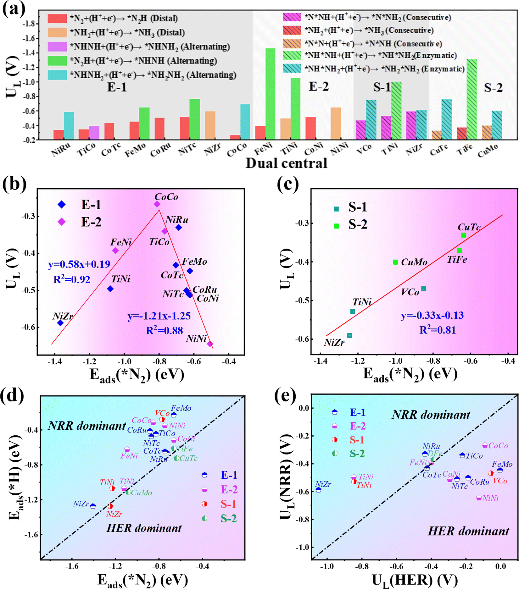
Next, we will explore the reaction mechanism and activity origin of the NRR of the six screened catalysts. Fig. 5a and d give the optimal NRR reaction pathways for NiRu@C9N4 (UL = −0.33 V), FeNi@C9N4 (UL = −0.35 V), TiNi@C9N4 (UL = −0.50 V), and NiZr@C9N4 (UL = −0.53 V) with N2 adsorption through the end-on configuration. Taking NiRu@C9N4 as an example (see Fig. 5a), the reaction of adsorbed N2 with hydrated protons produces an *N2H intermediate with an energy barrier of 0.33 eV. Next, H* attacks the N atom of the *N2H intermediate to form *N2H2 or *NHNH species, and H* favors the distal path due to the lower energy consumption for the formation of *N2H species. The proton–electron pair then reacts with *NNH2 to release the first ammonia molecule with a free energy drop of 0.27 eV. After that, the hydrated protons then attack the remaining *N atom three times in a row, eventually releasing a second NH3. Notably, the PDS of NiRu@C9N4via a distal mechanism is the first hydrogenation step (*N2 + *H+ + e− → *N2H), resulting in a UL of −0.33 V to make the whole NRR process spontaneously exothermic. A similar PDS is observed for FeNi@C9N4 (see Fig. 5b), while for TiNi@C9N4 (see Fig. 5c) and NiZr@C9N4 (see Fig. 5d), their PDSs are a remote mechanism of the last protonation step (*NH2 + *H+ + e− → *NH3). The proton–electron pair needs to overcome a large energy barrier to attack the *NH2 intermediate of N atoms; the energy barriers are 0.50 eV and 0.59 eV, respectively. | ||
| Fig. 5 Free energy diagrams of the NRR on (a) NiRu@C9N4, (b) FeNi@C9N4, (c) TiNi@C9N4 and (d) NiZr@C9N4 in the distal mechanism, (e) TiFe@C9N4 and (f) TiNi@C9N4 in the consecutive mechanism. Blue and red lines indicate free energy changes for the NRR at U = 0 V and UL, respectively. | ||
As shown in Fig. 5e and f, the optimal NRR reaction pathways for TiFe@C9N4 and TiNi@C9N4, whose N2 adsorption is through the side-on configuration, are consecutive pathways. Taking TiFe@C9N4 with the S-2 adsorption configuration as an example, its second protonation of the consecutive mechanism requires only 0.16 eV, so hydrated protons tend to attack the same N atom in succession. After the first NH3 was dissociated, H continued to attack the remaining N atom three times consecutively, and the last protonation step (*NH2 + *H+ + e− → *NH3) was a PDS with an energy barrier of 0.37 eV (see Fig. 5e). Differently, the PDS of TiFe@C9N4 adsorbed by N2 through the S-1 configuration is the second protonation step (*N2H + *H+ + e− → *N2H2) with an energy barrier of 0.53 eV.
In order to further understand the NRR behaviors of the five screened catalysts, TM1TM2@C9N4 (TM1TM2 = NiRu, FeNi, TiNi, NiZr, and TiFe), as shown in Fig. 6b–g, the partial densities of states (PDOS) of the catalysts after N2 adsorption and the crystal orbital Hamiltonian population (COHP) of the N2 molecule are analyzed. The PDOS and COHP of free N2 indicate that the 2π* orbital of N2 gas is far from the Fermi level and is an antibonding component, revealing the strong inertness of free N2 (see Fig. 6a). After N2 adsorption, obvious hybridization is found for the d states of TM1 and TM2 atoms and the 2p state of adsorbed N2 near the Fermi level for all catalysts, indicating that there is a strong bond between the catalysts and the adsorbed N2, ensuring that N2 can spontaneously adsorb on the active sites on the catalyst surface and being activated by the catalyst (see Fig. 6b–g). Obviously, some electron-occupied antibonding components of N2 appear below the Fermi level in all the systems, which also demonstrates its activation. Taking NiRu@C9N4 as an example, the 3σ and 2π orbitals of adsorbed N2 molecules donate electrons to the unoccupied d orbitals of Ni and Ru of the NiRu@C9N4 substrate, thereby enhancing the adsorption of N2 molecules. In addition, the occupied d orbitals of Ni and Ru atoms donate electrons back to the 2π* antibonding orbitals of N2 molecules, resulting in the separation of the 2π* antibonding orbitals into occupied and unoccupied orbitals.
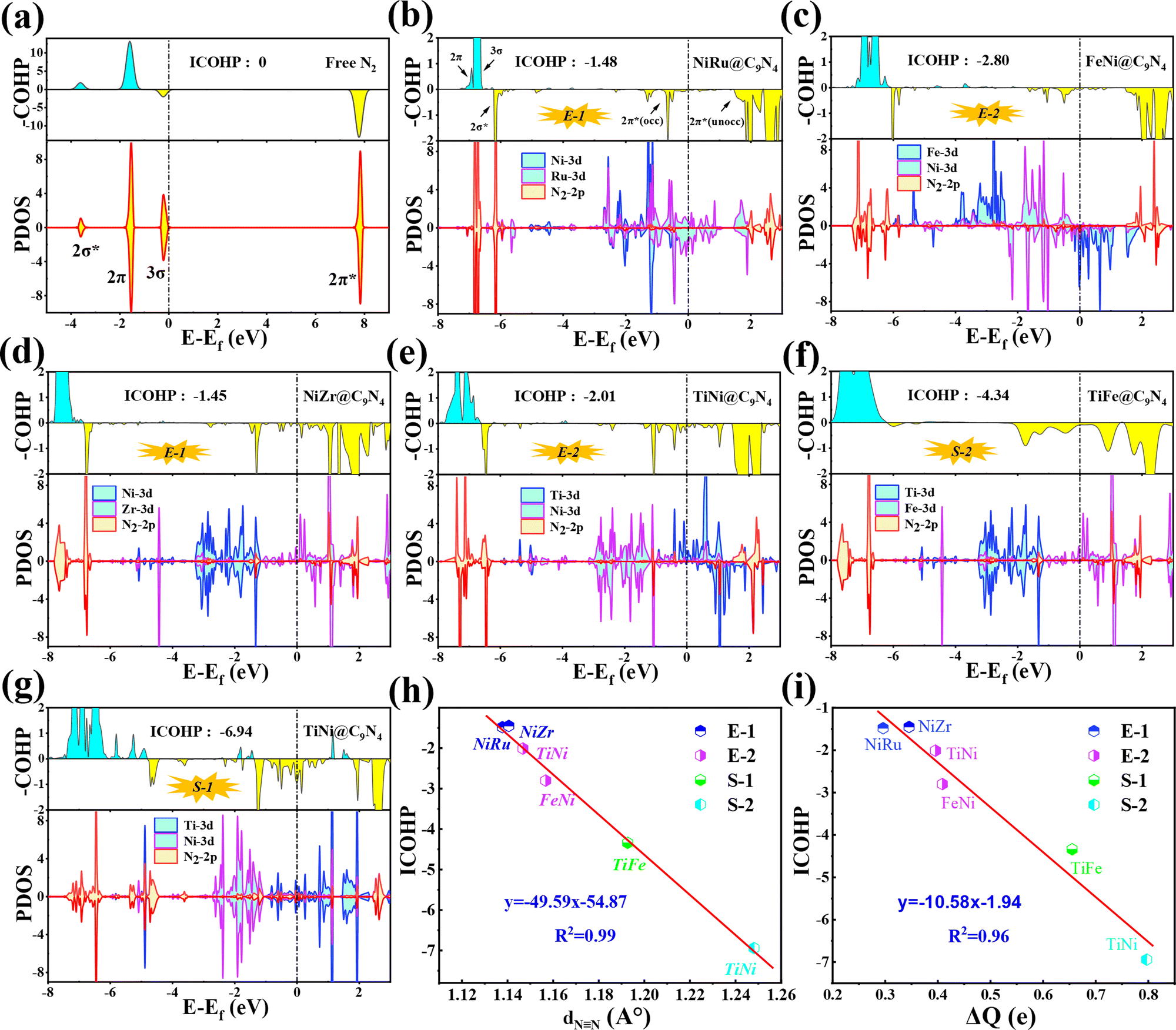 | ||
| Fig. 6 (a) Partial density of states (PDOS) and molecular orbitals of a free N2 molecule. (b–f) PDOS, crystal orbital Hamilton populations (COHPs), and integrated COHP (ICOHP) of *N2 on NiRu@C9N4, FeNi@C9N4, TiNi@C9N4, and NiZr@C9N4 through the end-on configuration, and (g) TiFe@C9N4 and (h) TiNi@C9N4 through the side-on configuration. (h) Illustration of the correlation between ICOHP and NN bond length of N2 (dNN). (i) Illustration of the correlation between ICOHP and ΔQ. The bonding and antibonding states in COHP are denoted by cyan and yellow, respectively. | ||
In addition, the activation of the NN bond can also be confirmed by analyzing the integrated crystal orbital Hamilton population (ICOHP) values (see Fig. 6b–g). Our results show that the ICOHP values for N2 on all the studied catalysts are negative, around −6.94 to −1.45 eV, indicating that the N2 molecule is well activated. Interestingly, there is a strong linear relationship between the ICOHP value and the NN bond length of the adsorbed N2; that is, a more negative ICOHP corresponds to a longer NN bond length. Similarly, such a linear relationship can also be determined between ICOHP and the charge transferred to the adsorbed N2 (ΔQ) (see Fig. 6i). It is noted that the more charges transferred to the N2, the weaker the interaction between the NN bonds and the more negative the values of ICOHP.
In order to confirm the influence of the solvent effect, we chose NiRu@C9N4 and TiFe@C9N4 to perform several test calculations with and without considering the effect of solvation (see Fig. S8, ESI†). Although the free energies of the adsorbed species for both NiRu@C9N4 and TiFe@C9N4 in the distal mechanism are slightly more negative with the consideration of the solvation effect, similar energy diagrams are identified for both cases. Moreover, the differences of UL during the full NRR processes of NiRu@C9N4 and TiFe@C9N4 with and without considering the solvation effect are only −0.12 V and −0.08 V. Based on this, we can conclude that the reaction energies are not significantly affected by those solvation molecules.
3.6. Possibility of the experimental synthesis of TM1TM2@C9N4
Finally, we extended the possibility of the experimental synthesis of these screened TM1TM2@C9N4 catalysts. First, we calculated their formation energies using the following equation: | (4) |
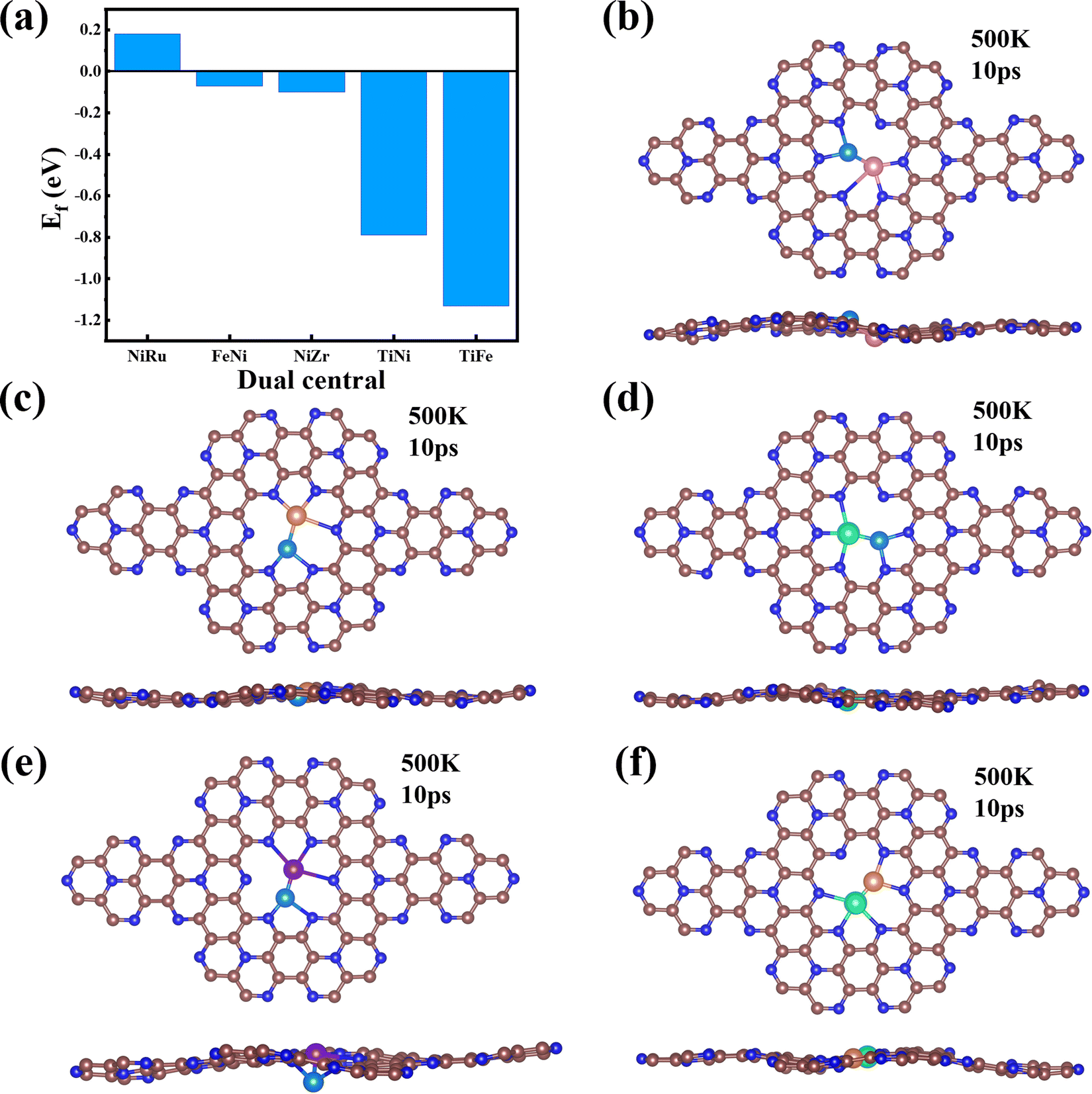 | ||
| Fig. 7 (a) Formation energies of NiRu@C9N4, FeNi@C9N4, TiNi@C9N4, NiZr@C9N4, and TiFe@C9N4. (b–f) Top and side views of the configurations of NiRu@C9N4, FeNi@C9N4, TiNi@C9N4, NiZr@C9N4, and TiFe@C9N4 after AIMD simulations. The simulations were performed at 500 K for 10 ps with a time step of 2 fs. | ||
It is well known that the NRR active sites of catalyst basal planes can be easily covered by various functional groups under certain reaction conditions; if yes, the reaction areas in their basal planes will be largely decreased.53,54 To address the concern whether the surfaces of the catalysts are blocked by *O/*OH like electron-accepting species or not, we constructed the surface Pourbaix diagrams of the 5 screened TM1TM2@C9N4 (TM1TM2 = NiRu, FeNi, TiNi, TiFe, and NiZr) catalysts by plotting the equilibrium potential between different surface terminations, including –O, –OH, and –H2O terminated systems, as a function of pH (see Fig. S14, ESI†). The optimal structures for *O, *OH, and *H2O adsorption are provided in Fig. S15 (ESI†). We first considered the situation with 0 V vs. SHE to unveil their surface composition at the cathode surface under operating conditions. Clearly, all the TM1TM2@C9N4 systems can adsorb the oxygen and hydroxyl groups onto their bare surfaces to form O*/OH*. Specifically, 3 TM1TM2@C9N4 (TM1TM2 = TiNi, TiFe, and NiZr) can be fully terminated by O*; FeNi@C9N4 can be occupied by OH*; whereas for NiRu@C9N4, both O* and OH* can be adsorbed on the basal plane depending on the pH value of the electrolyte. When an electrode potential is applied, the protonation of O*/OH* is gradually favorable on these TM1TM2@C9N4 surfaces. The redox potential (UR), which is defined as the electrode potential needed to remove the surface O*/OH* species, could be compared to the UL of the NRR. Except NiZr@C9N4 with UR being higher than UL, the four other TM1TM2@C9N4 systems cannot be influenced by the *O/*OH species under working conditions.
4. Conclusions
In conclusion, by first-principles high-throughput calculations, a 6-step screening criterion is set to identify promising candidate catalysts of TM1TM2@C9N4 for the NRR. Our calculations show that the heteronuclear dual-metal catalysts NiRu@C9N4, FeNi@C9N4, TiFe@C9N4, TiNi@C9N4, and NiZr@C9N4 are considered as promising NRR electrocatalyst candidates with good confinement potentials of −0.33 V, −0.35 V, −0.37 V, −0.50 V, and −0.59 V. In addition, we also confirmed the high selectivity and stability of these 5 catalysts. The systematic study shows that for the TM1TM2@C9N4 catalyst with dual-atom active sites, the different adsorption configurations of N2 have obvious differences in the origin of the catalytic activity, indicating that it is of great significance to explore the most stable adsorption configuration of N2. Our findings not only provide a useful dataset for the experimental exploration of TM1TM2@C9N4 catalysts, but also provide a reference to guide the rational design of novel high-performance NRR catalysts for the sustainable production of ammonia.Conflicts of interest
There are no conflicts to declare.Acknowledgements
This work is supported by the NSFC (2022M711691, 22203046, and 12204404), the Open Funds of the State Key Laboratory of Rare Earth Resource Utilization (RERU2021011), and the Six talent peaks project in Jiangsu Province (XCL-104). We thank the computational resources at Yangzhou University and Hebei Normal University.References
- J. Erisman, M. Sutton, J. Galloway, Z. Klimont and W. Winiwarter, Nat. Geosci., 2008, 1, 636–639 Search PubMed.
- J. Galloway, A. Townsend, J. Erisman, M. Bekunda, Z. Cai, J. Freney, L. Martinelli, S. Seitzinger and M. Sutton, Science, 2008, 320, 889–892 Search PubMed.
- J. Montoya, C. Tsai, A. Vojvodic and J. Nørskov, ChemSusChem, 2015, 8, 2180–2186 Search PubMed.
- X. Cui, C. Tang and Q. Zhang, Adv. Energy Mater., 2018, 8, 1800369 CrossRef.
- X. Xue, R. Chen and C. Yan, Nano Res., 2019, 12, 1229–1249 CrossRef CAS.
- X. Guo, J. Gu, S. Lin, S. Zhang, Z. Chen and S. Huang, J. Am. Chem. Soc., 2020, 142, 5709–5721 Search PubMed.
- X. Liu, Y. Jiao, Y. Zheng, M. Jaroniec and S. Qiao, J. Am. Chem. Soc., 2019, 14, 9664–9672 Search PubMed.
- Q. Zhang, F. Meng, H. Zhong, M. Shi, Y. Zhang, J. Yan, Q. Jiang and X. Zhang, Adv. Mater., 2017, 29, 1604799 Search PubMed.
- J. Montoya, C. Tsai, A. Vojvodic and J. Nørskov, ChemSusChem, 2015, 8, 2180–2186 CrossRef CAS PubMed.
- J. Yang, Y. Guo, R. Jiang, F. Qin, H. Zhang, W. Lu, J. Wang and J. Yu, J. Am. Chem. Soc., 2018, 140, 8497–8508 Search PubMed.
- H. Zhou, Y. Qu, J. Li, Z. Wang, C. Yang and Q. Jiang, Appl. Catal., B, 2022, 305, 121023 CrossRef CAS.
- J. Zhao and Z. Chen, J. Am. Chem. Soc., 2017, 139, 12480–12487 CrossRef CAS PubMed.
- Y. Lin, Y. Feng, H. Zhou, Y. Han, H. Sun, L. Shi, L. Meng, M. Zhou, Y. Liu and X. Zhang, Appl. Surf. Sci., 2022, 593, 153338 CrossRef CAS.
- A. Wang, J. Li and T. Zhang, Nat. Rev. Chem., 2018, 2, 65–81 Search PubMed.
- L. Xu, L. Yang and E. Ganz, ACS Appl. Mater., 2021, 13, 14091–14101 CrossRef CAS PubMed.
- X. Wang, W. Wang, M. Qiao, G. Wu, W. Chen, T. Yuan, Q. Xu, M. Chen, Y. Zhang, X. Wang, J. Wang, J. Ge, X. Hong, Y. Li, Y. Wu and Y. Li, Sci. Bull., 2018, 63, 1246–1253 Search PubMed.
- Y. Zhang, J. Hu, C. Zhang, Y. Liu, M. Xu, Y. Xue, L. Liu and M. Leung, J. Mater. Chem. A, 2020, 8, 9091 RSC.
- Z. Geng, Y. Liu, X. Kong, P. Li, K. Li, Z. Liu, J. Du, M. Shu, R. Si and J. Zeng, Adv. Mater., 2018, 30, 1803498 CrossRef PubMed.
- L. Hui, Y. Xue, H. Yu, Y. Liu, Y. Fang, C. Xing, B. Huang and Y. Li, J. Am. Chem. Soc., 2019, 141, 10677–10683 CrossRef CAS PubMed.
- Y. Wang, X. Cui, J. Zhao, G. Jia, L. Gu, Q. Zhang, L. Meng, Z. Shi, L. Zheng, C. Wang, Z. Zhang and W. Zheng, ACS Catal., 2019, 9, 336–344 Search PubMed.
- C. Choi, S. Back, N. Kim, J. Lim, Y. Kim and Y. Jung, ACS Catal., 2018, 8, 7517–7525 Search PubMed.
- H. Fei, T. Guo, Y. Xin, L. Wang, R. Liu, D. Wang, F. Liu and Z. Wu, Appl. Catal., B, 2022, 300, 120733 Search PubMed.
- J. Yin, J. Li, Y. Hang, J. Yu, G. Tai, X. Li, Z. Zhang and W. Guo, Small, 2016, 12, 2942–2968 Search PubMed.
- T. Yang, T. Song, J. Zhou, S. Wang, D. Chi, L. Shen, M. Yang and Y. Feng, Nano Energy, 2020, 68, 104304 CrossRef CAS.
- D. Jiao, Y. Liu, Q. Cai and J. Zhao, J. Mater. Chem. A, 2021, 9, 1240–1251 RSC.
- J. Chen, H. Cao, J. Chen, S. Qian, G. Xia, Y. Wang and J. Li, J. Phys. Chem. C, 2021, 125, 19821–19830 CrossRef CAS.
- Y. Le, J. Gua and W. Tian, Chem. Commun., 2014, 50, 13319–13322 RSC.
- W. Zhao, L. Zhang, Q. Luo, Z. Hu, W. Zhang, S. Smith and J. Yang, ACS Catal., 2019, 9, 3419–3425 Search PubMed.
- D. Jiao, Y. Liu, Q. Cai and J. Zhao, J. Mater. Chem. A, 2021, 9, 1240–1251 Search PubMed.
- P. Ou, X. Zhou, F. Meng, C. Chen, Y. Chen and J. Song, Nanoscale, 2019, 11, 13600–13611 RSC.
- Y. Zhang, J. Hu, C. Zhang, Y. Liu, M. Xu, Y. Xue, L. Liu and M. Leung, J. Mater. Chem. A, 2020, 8, 9091–9098 RSC.
- S. Yang, C. Zhang, D. Rao and X. Yan, Chin. J. Catal., 2022, 43, 1139–1147 CrossRef CAS.
- Y. Li, Q. Zhang, C. Li, H. Fan, W. Luo, H. Liua and S. Dou, J. Mater. Chem. A, 2019, 7, 22242–22247 RSC.
- T. Deng, C. Cen, H. Shen, S. Wang, J. Guo, S. Cai and M. Deng, J. Phys. Chem. Lett., 2020, 11, 6320–6329 CrossRef CAS PubMed.
- X. Zheng, Y. Yao, Y. Wang and Y. Liu, Nanoscale, 2020, 12, 9696–9707 RSC.
- G. Zheng, L. Li, Z. Tian, X. Zhang and L. Chen, J. Energy Chem., 2021, 54, 612–619 CrossRef CAS.
- S. Ji, Y. Chen, Q. Fu, Y. Chen, J. Dong, W. Chen, Z. Li, Y. Wang, L. Gu, W. He, C. Chen, Q. Peng, Y. Huang, X. Duan, D. Wang, C. Draxl and Y. Li, J. Am. Chem. Soc., 2017, 139, 9795–9798 CrossRef CAS PubMed.
- L. Xia, H. Wang and Y. Zhao, J. Mater. Chem. A, 2021, 9, 20615–20625 RSC.
- X. Lv, W. Wei, B. Huang, Y. Dai and T. Frauenheim, Nano Lett., 2021, 21, 1871–1878 CrossRef CAS PubMed.
- H. Chen, S. Zhang, W. Jiang, C. Zhang, H. Guo, Z. Liu, Z. Wang, F. Liu and X. Niu, J. Mater. Chem. A, 2018, 6, 11252–11259 RSC.
- Y. Zhou, G. Gao, J. Kang, W. Chu and L. Wang, Nanoscale, 2019, 11, 18169–18175 Search PubMed.
- Z. Xue, X. Zhang, J. Qin and R. Liu, Nano Energy, 2021, 80, 105527 CrossRef CAS.
- G. Kresse and J. Hafner, Phys. Rev. B: Condens. Matter Mater. Phys., 1993, 48, 13115 Search PubMed.
- G. Kresse and J. Hafner, Phys. Rev. B: Condens. Matter Mater. Phys., 1993, 47, 558 Search PubMed.
- G. Kresse and D. Joubert, Phys. Rev. B: Condens. Matter Mater. Phys., 1999, 59, 1758–1775 CrossRef CAS.
- J. Perdew, K. Burke and Y. Wang, Phys. Rev. B: Condens. Matter Mater. Phys., 1996, 54, 16533–16539 CrossRef CAS PubMed.
- J. Perdew, K. Burke and M. Ernzerhof, Phys. Rev. Lett., 1996, 77, 3865 CrossRef CAS PubMed.
- S. Nose, J. Chem. Phys., 1984, 81, 511–519 Search PubMed.
- J. Montoya, C. Tsai, A. Vojvodic and J. Nørskov, ChemSusChem, 2015, 8, 2180–2186 CrossRef CAS PubMed.
- A. Peterson, F. Abild-Pedersen, F. Studt, J. Rossmeisl and J. Nørskov, Energy Environ. Sci., 2010, 3, 1311–1315 Search PubMed.
- P. Sabatier, Hydrogenations et deshydrogenations par catalyse, Ber. Dtsch. Chem. Ges., 1911, 44, 1984–2001 CrossRef CAS.
- X. Wang and L. Yang, Appl. Surf. Sci., 2022, 576, 151839 CrossRef CAS.
- X. Guo, S. Lin, J. Gu, S. Zhang, Z. Chen and S. Huang, Adv. Funct. Mater., 2021, 31, 2008056 CrossRef CAS.
- X. Zhu, X. Zhou, Y. Jing and Y. Li, Nat. Commun., 2021, 12, 4080 CrossRef CAS PubMed.
Footnotes |
| † Electronic supplementary information (ESI) available. See DOI: https://doi.org/10.1039/d2nh00451h |
| ‡ Jinxin Sun, Peng Xia, and Yuxing Lin contributed equally to this work. |
| This journal is © The Royal Society of Chemistry 2023 |