
 Open Access Article
 This Open Access Article is licensed under a Creative Commons Attribution-Non Commercial 3.0 Unported Licence
In situ silver nanoparticle development for molecular-specific biological imaging via highly accessible microscopies†
Dae-Hyeon
Song
 a,
Chang Woo
Song
a,
Jinkyoung
Chung
b,
Eun-Hae
Jang
c,
Hyunwoo
Kim
a,
Yongsuk
Hur
d,
Eun-Mi
Hur
ce,
Doory
Kim
*b and
Jae-Byum
Chang
*a
a,
Chang Woo
Song
a,
Jinkyoung
Chung
b,
Eun-Hae
Jang
c,
Hyunwoo
Kim
a,
Yongsuk
Hur
d,
Eun-Mi
Hur
ce,
Doory
Kim
*b and
Jae-Byum
Chang
*a
aDepartment of Materials Science and Engineering, Korea Advanced Institute of Science and Technology, Daejeon, Korea. E-mail: jbchang03@kaist.ac.kr
bDepartment of Chemistry, Hanyang University, Seoul, Korea. E-mail: doorykim@hanyang.ac.kr
cLaboratory of Neuroscience, Research Institute for Veterinary Science, College of Veterinary Medicine, Seoul National University, Seoul, Korea
dBioMedical Research Center, Korea Advanced Institute of Science and Technology, Daejeon, Korea
eBK21 Four Future Veterinary Medicine Leading Education & Research Center, Seoul National University, Seoul, Korea
First published on 21st December 2022
Abstract
In biological studies and diagnoses, brightfield (BF), fluorescence, and electron microscopy (EM) are used to image biomolecules inside cells. When compared, their relative advantages and disadvantages are obvious. BF microscopy is the most accessible of the three, but its resolution is limited to a few microns. EM provides a nanoscale resolution, but sample preparation is time-consuming. In this study, we present a new imaging technique, which we termed decoration microscopy (DecoM), and quantitative investigations to address the aforementioned issues in EM and BF microscopy. For molecular-specific EM imaging, DecoM labels proteins inside cells using antibodies bearing 1.4 nm gold nanoparticles (AuNPs) and grows silver layers on the AuNPs' surfaces. The cells are then dried without buffer exchange and imaged using scanning electron microscopy (SEM). Structures labeled with silver-grown AuNPs are clearly visible on SEM, even they are covered with lipid membranes. Using stochastic optical reconstruction microscopy, we show that the drying process causes negligible distortion of structures and that less structural deformation could be achieved through simple buffer exchange to hexamethyldisilazane. Using DecoM, we visualize the nanoscale alterations in microtubules by microtubule-severing proteins that cannot be observed with diffraction-limited fluorescence microscopy. We then combine DecoM with expansion microscopy to enable sub-micron resolution BF microscopy imaging. We first show that silver-grown AuNPs strongly absorb white light, and the structures labeled with them are clearly visible on BF microscopy. We then show that the application of AuNPs and silver development must follow expansion to visualize the labeled proteins clearly with sub-micron resolution.
Introduction
In bioimaging, target molecules must be tagged with materials that have a high electron or light contrast.1–3 To create light contrast in light microscopy imaging, light-absorbing or light-emitting materials are used in brightfield (BF) and fluorescent microscopy (FM), respectively. In electron microscopy (EM), materials with a high electron density are used. All of these imaging modalities are widely employed in biological research and diagnosis, but their strengths and drawbacks are evident in terms of resolution,4,5 multiplexing capability,6 and instrumentation needs.7,8 BF microscopy requires the simplest microscope setup and is the most common type of microscopy available in biological laboratories and hospitals. However, their resolution is only 1 to 2 microns because structures are blurred by white light. FM with ordinary diffraction-limited microscopy has a resolution of 250 nm.9 An even higher resolution can be achieved using super-resolution fluorescence microscopes;10 however, these microscopes are not readily available in most hospitals or laboratories. EM, particularly scanning electron microscopy (SEM), has a resolution comparable to or greater than that of super-resolution optical microscopy and is commonly available in most research institutes.11 However, its multiplexing capability is limited.6 Additionally, complicated sample preparation techniques, such as ultrathin sectioning7 or focused ion beam (FIB) milling,8 are required to image intracellular proteins, even in cultured cells.12 Recently, correlative light and electron microscopy (CLEM) techniques have been developed to compensate for the limitation of FM and EM.13,14 CLEM has been widely used as a super-resolution molecular-specific imaging technique because it can simultaneously provide high-resolution and multiplexed imaging capabilities.Numerous studies have been performed to address the aforementioned issues of the three imaging modalities and to expand their applications. An imaging approach known as expansion microscopy (ExM) has been developed to allow super-resolution fluorescence imaging without the requirement for specialized equipment.15 ExM enables the imaging of cultured cells and tissue slices with a sub-100 nm resolution by physically expanding them. However, ExM relies on fluorophores; hence, it cannot be applied directly to BF microscopy, which requires light-absorbing materials for molecular imaging. Due to this limitation, sub-micron resolution BF microscopy imaging by applying ExM to BF microscopy has not yet been demonstrated. In a prior study, molecular-specific SEM imaging was performed by tagging proteins inside cells with metal nanoparticles and drying the cells without complex sample preparation processes, such as FIB milling or ultrathin sectioning.16 However, in such studies, the images were not quantitatively assessed in terms of the resolution, labeling density, and distortion of structures during the drying process. Furthermore, multiplexed imaging of proteins using this method has yet to be established. Due to these limitations, multiplexed molecular imaging with SEM has not been widely employed.
In this study, we present a series of sample preparation procedures, which we termed decoration microscopy (DecoM), and quantitative investigations to address the aforementioned issues in EM and BF microscopy. First, we show that labeling proteins inside cells with antibodies bearing 1.4 nm gold nanoparticles (AuNPs), developing silver onto the AuNPs, and simply drying the cells make the labeled target proteins readily visible on SEM. Using stochastic optical reconstruction microscopy (STORM)17 imaging, we show that the distortion of structures is negligible and that the imaging resolution is 47 nm. After confirming the distortion, we demonstrated multiplexed imaging of proteins by imaging specimens using FM and SEM and superimposing the images. Next, we combined our method with ExM to provide BF microscopy with sub-micron resolution. We show that the labeling of target molecules with antibodies bearing 1.4 nm AuNPs and silver development should be performed after expansion to produce a high light contrast in BF microscopy. Using this approach, we imaged neurites in thick mouse brain slices with a sub-micron resolution using BF microscopy. ExM has now been applied to a variety of specimen types, including clinical specimens,18 mouse organs,19,20 Caenorhabditis elegans,21 Drosophila melanogaster,22 zebrafish larvae,23 and even whole mouse embryos.24 The sub-micron resolution imaging of BF microscopy demonstrated in this study will significantly expand the application of BF microscopy to a wide variety of specimens.
Results and discussion
DecoM: decoration microscopy
We first demonstrated the molecular-specific imaging of intracellular proteins via DecoM with SEM. We stained cultured cells with regular primary antibodies and fragment containing antigen-binding region (Fab) of secondary antibodies bearing both fluorophores and AuNPs with a diameter of 1.4 nm (Fig. 1a).25 Antibodies-labeled colloidal gold nanoparticle (5–10 nm) probes are less stable than covalent conjugated probes. Moreover, when using colloidal nanoparticles, it is necessary to understand the aggregate dynamics to prevent aggregation.26,27 Furthermore, antibody-labeled colloidal gold nanoparticles present problems with labeling and penetration due to their size.28 The small sizes of the Fab fragments, which are about one-third smaller in size than whole Immunoglobulin G (IgG), and 1.4 nm AuNPs enhanced the labeling density and penetration depth.28,29 The stained cells were then imaged with confocal microscopy to acquire images of the labeled proteins (inset of Fig. 1b). After confocal microscopy imaging, in situ silver development (see the ‘in situ silver development and ambient condition drying of cells’ in Methods section) was performed inside cells to develop silver nanoparticles (AgNPs) from the AuNPs of the secondary antibodies. Specific silver development on the AuNPs with a lesser non-specific background was achieved through the catalyzed reduction of silver ions.30 The surface of the AuNPs acted as nuclei and transferred the electrons from a reductant (e.g., hydroquinone31) to the silver ions. Furthermore, a capping agent, known as a protective agent (e.g., gum arabic32), was essential in the specific silver development by controlling the reduction rate of the silver ions. With such a capping agent, the non-specific development of silver from negatively charged molecules (i.e., proteins and nucleic acids) was successfully suppressed. As shown in ESI Fig. 1,† the labeled protein structures were not visible in BF microscopy before silver development, but these structures became apparent afterward. Once the silver development was complete, the cells were washed with distilled water (DW), dried at room temperature without any treatment, and coated with thin layers of conductive materials, such as osmium or platinum. The specimens were then imaged with SEM (Fig. 1b). When the FM and SEM images were overlaid, the labeled protein structures shown in the FM and SEM images, which were microtubules, matched without any noticeable deformation or distortion, as shown in Fig. 1c. Further, when using the backscattered electron detector, the silver structures covered by the organic layers were more clearly resolved (ESI Fig. 2†). In the FM image, the three closely positioned microtubules were not clearly resolved due to the diffraction limit of light. However, they were resolved in the SEM image due to the narrow point-spread function of the SEM, as shown in Fig. 1d. Furthermore, we applied DecoM to clathrin molecules. Clathrin forms a polyhedral structure that surrounds vesicles with an average diameter of 150 nm.33 Due to the small size of the internal hollow space of the clathrin-coated pits (CCP), they have been used as a test structure for super-resolution imaging.15,33 The internal hollow spaces were not resolved with diffraction-limited confocal microscopy but were clearly resolved in the SEM imaging (ESI Fig. 3†). Through this experiment, we confirmed that the staining of proteins via antibodies bearing both fluorophores and AuNPs, the development of silver on AuNPs, and the drying of specimens in ambient conditions, followed by SEM imaging, allowed for the super-resolution imaging of target proteins.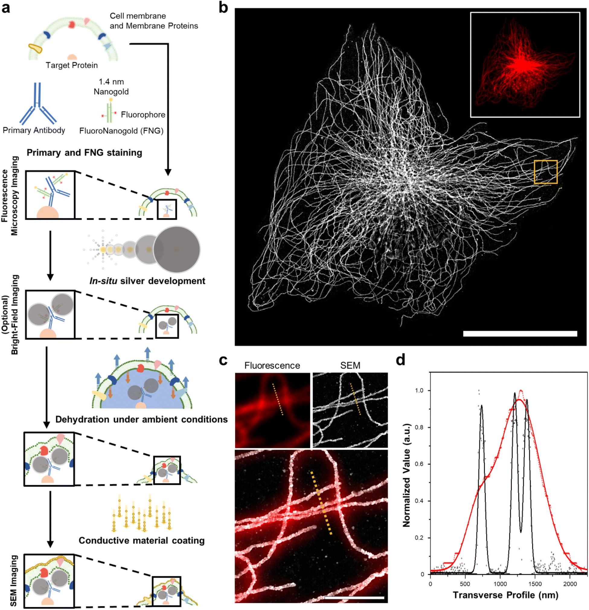 | ||
| Fig. 1 Schematic of DecoM. (a) The workflow includes in situ silver development, drying under ambient conditions, and a conductive material coating. (b) SEM image of β-tubulin labeled BS-C-1 cell obtained by DecoM (inset fluorescence image at the same region). (c) Magnified images in the yellow-boxed region in (b). (d) The signal profiles of fluorescence (red dot) and SEM (black dot) along the yellow dotted line in the images in (c) with Gaussian fit (solid line). The acceleration voltage of SEM is 10 kV, and the wavelength of a laser in fluorescence microscopy is 637 nm. Scale bar: (b) 30 μm, (c) 2 μm. | ||
Study of the deformation of protein structures after drying
Next, we studied the distortion of protein structures after drying and the effect of silver development time. First, we studied the macroscopic deformation of cells after drying. The distances between the two landmarks of cells were measured from the FM and SEM images and then compared (Fig. 2a and ESI Fig. 4†). As shown in Fig. 2b, the distances between the landmarks measured from the FM and SEM images showed a 2.5% difference, indicating that the drying process did not induce significant macroscopic deformation of the cells. We also measured the deformation of specimens prepared through more controlled drying processes. We first exchanged the buffer of specimens from DW to hexamethyldisilazane (HMDS) and dried the specimens at room temperature. Second, we exchanged the buffer of the specimens for ethanol and then dried them using a critical point dryer (CPD). We then measured the deformations of the structures prepared with these two controlled drying processes in the same way as the deformation measurements shown in Fig. 2a and b. Interestingly, all three drying processes showed negligible structural deformation, especially in the peripheral regions of the cells. Around the nucleus, specimens prepared with more controlled drying processes, such as those dried after buffer exchange to HMDS and prepared using CPD, showed reduced deformation (Fig. 2c and ESI Fig. 5 and 6†). Such deformation observed in the specimen dried at room temperature without buffer exchange was probably due to the nucleus beneath the microtubules after drying. Such a non-zero thickness layer beneath the microtubules might induce the deformation of the microtubules.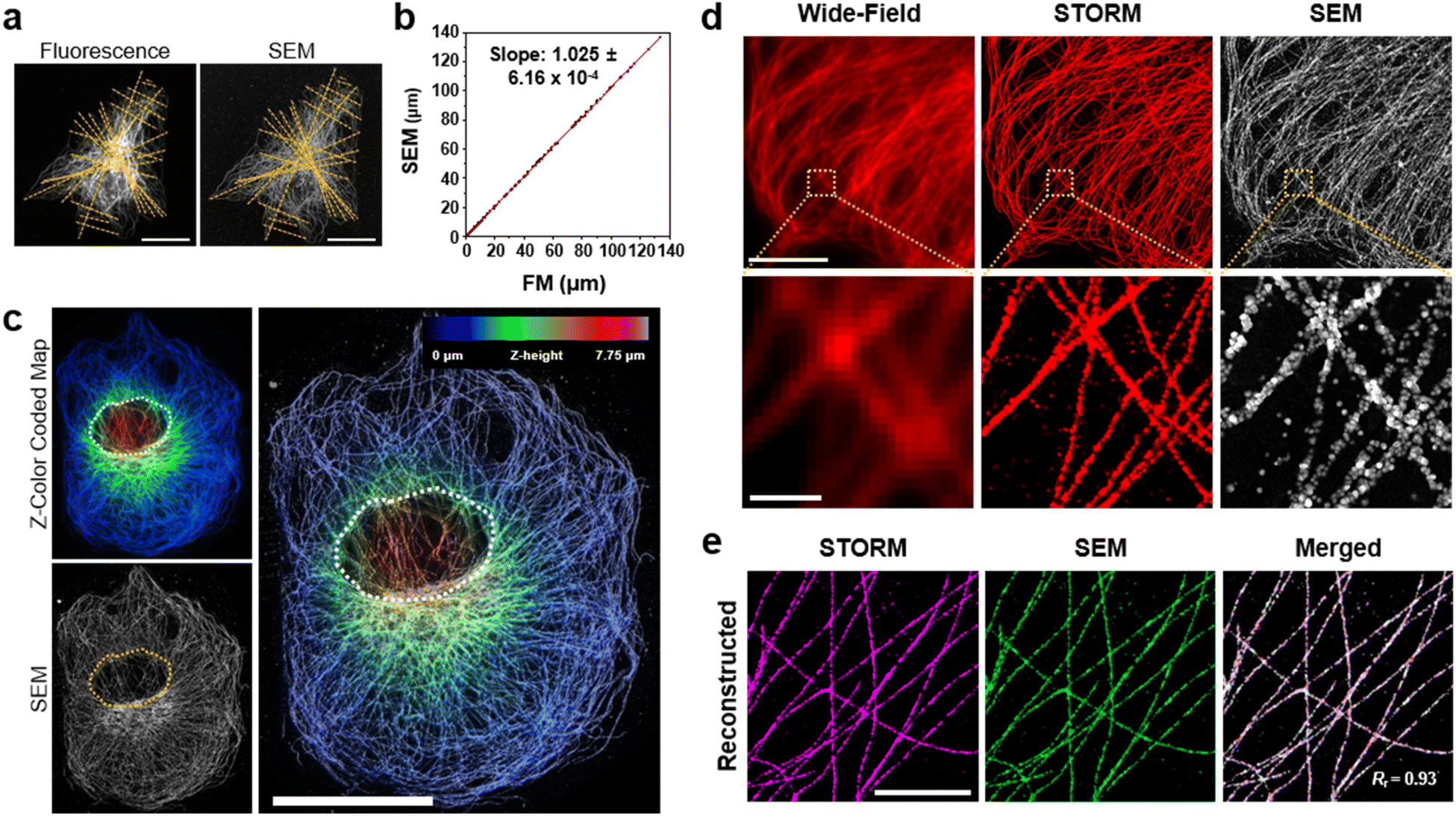 | ||
| Fig. 2 Characterization of deformation during drying under ambient conditions. (a) β-Tubulin labeled BS-C-1 cell images with lines for the confirmation of macroscopic deformation by cell size comparison. (b) Plot of lengths measured from the SEM image against those from the same position on the FM image. The points in b were obtained through 20 measurements, each from seven different cells, and a linear fit is shown as a red line (R-square: 0.9995). (c) Correlative analysis of the Z-color-coded map of confocal microscopy and SEM images. The step size in the color-coded map is 0.25 μm, and the overlay opacity is 50% (white and yellow dotted regions: the nucleus of the cell). (d) Corresponding images by wide-field microscopy, STORM (pre-in situ silver development), and SEM (post-in situ silver development). (e) Signal-reconstructed images of STORM, SEM, and merged images at the different cells showed high correlation with Pearson's coefficient, Rr = 0.93 (magenta: STORM, green: SEM). Scale bar: (a) 30 μm, (c) 20 μm, (d) 10 μm, 1 μm, (e) 3 μm. | ||
We further studied the deformation and preservation of the structures of microtubules at the periphery of the cells. To measure deformation at a nanoscale resolution, we imaged cultured cells with STORM and SEM (Fig. 2d). We stained cultured cells with a primary antibody against tubulin and Fab fragments of secondary antibodies bearing Alexa Fluor 647 and AuNPs (Fig. 1a). We then performed STORM imaging and proceeded to drying at room temperature and SEM imaging. Having validated the macroscopic and microscopic deformation of the dried structures, we studied whether the signal intensity observed in the SEM images matched the signal intensity observed in the STORM images. However, when the correlation coefficient was calculated from the original images, it showed a low value. This could mainly be attributed to the distinction in probe sizes, not the distortion of structures. The average width of the microtubules in the SEM images measured from the regions where the STORM imaging (=46.70 nm) was performed was around 87 nm, as illustrated in ESI Fig. 7.† The varying widths were due to the range of the size of organic fluorophores with a size of 1 or 2 nm, the imaging modality of STORM, and silver particles with a size of 15 nm, the imaging modality of SEM. Furthermore, another reason is a significant variation in the microtubule width measured from SEM in Fig. 7† and a discontinuous feature of silver particles after STORM imaging performed compared to conventional FM imaging (ESI Fig. 8†). Previous studies have reported a similar phenomenon: a considerable variation in the number of silver-grown AuNPs was observed when the AuNPs were exposed to intensive illumination before silver development.34,35 The photochemical damage applied to the AuNPs during the STORM imaging may be attributed to these results. Therefore, correlation analysis was performed using a mutual image as a mask to compensate for the size of the imaging modality and what occurred after STORM imaging. The STORM and SEM images were then reconstructed using only the selected pixels. In Fig. 2e and ESI Fig. 9, and 10,† the two reconstructed images showed a high degree of match in their signal intensities with a Pearson's coefficient of Rr = 0.93. Such a high Pearson's coefficient was also observed in the correlation analysis of conventional FM and SEM images (ESI Fig. 11 and 12†). These results show that the signal intensities observed in the FM and SEM images were highly correlated.
The effect of in situ silver development time on protein structures
Next, we studied the resolution of DecoM. In DecoM, the resolution depended mainly on the size of the AgNPs developed on the AuNPs. We found that the silver development process was essential for observing the labeled structures with SEM. When the specimens were stained with primary and secondary antibodies bearing AuNPs and then dried and imaged with SEM, the signal-to-noise ratio (SNR) was not high enough to clearly distinguish the labeled structures from the backgrounds (ESI Fig. 13†). After drying, the AuNPs were covered by unlabeled biomolecules, such as cytoplasmic proteins, actin networks,36 and lipid membranes.37 Such thick molecular layers on the AuNPs decreased the SNR of the AuNPs in the SEM imaging. To increase the SNR, we developed AgNPs on the surface of the AuNPs for varying development times. As shown in ESI Fig. 9,† the signal intensity increased with a longer silver development time. We then studied how the resolution of DecoM depends on the silver development time.A longer silver development time increased the signal intensity; however, it also decreased the resolution (Fig. 3a and b, and ESI Fig. 14†). As shown in Fig. 3b, the full-width at half-maximum (FWHM) of the microtubules increased from 93.72 ± 11.13 to 101.62 ± 11.62 when the silver development time increased from 10 to 60 min. To understand the FWHM of the microtubules, we measured the diameters of the silver-developed AuNPs. After silver development, we embedded the cells in resin and sectioned them to a thickness of 300 nm using an ultramicrotome, except for osmium tetroxide fixation. The sections were then imaged with scanning transmission electron microscopy (STEM) equipped with an EDX detector (Fig. 3c). Through this experiment, we confirmed that the particles that developed along the microtubules were made mainly of silver, as shown in Fig. 3d. We also analyzed the average diameter of the silver-developed AuNPs using the top images according to the silver development time in Fig. 3c. The average diameter of the AgNPs was 14.36 nm after 10 min of silver development and increased to 17.66 nm after 60 min of silver development (Fig. 3e). The size of the AgNPs did not further increase even after more than 60 min of development, possibly due to the depletion of silver precursors in the solution. Microtubules with a larger FWHM and higher signal intensities were achieved when the silver development was repeated multiple times with fresh silver development solutions (ESI Fig. 15†).
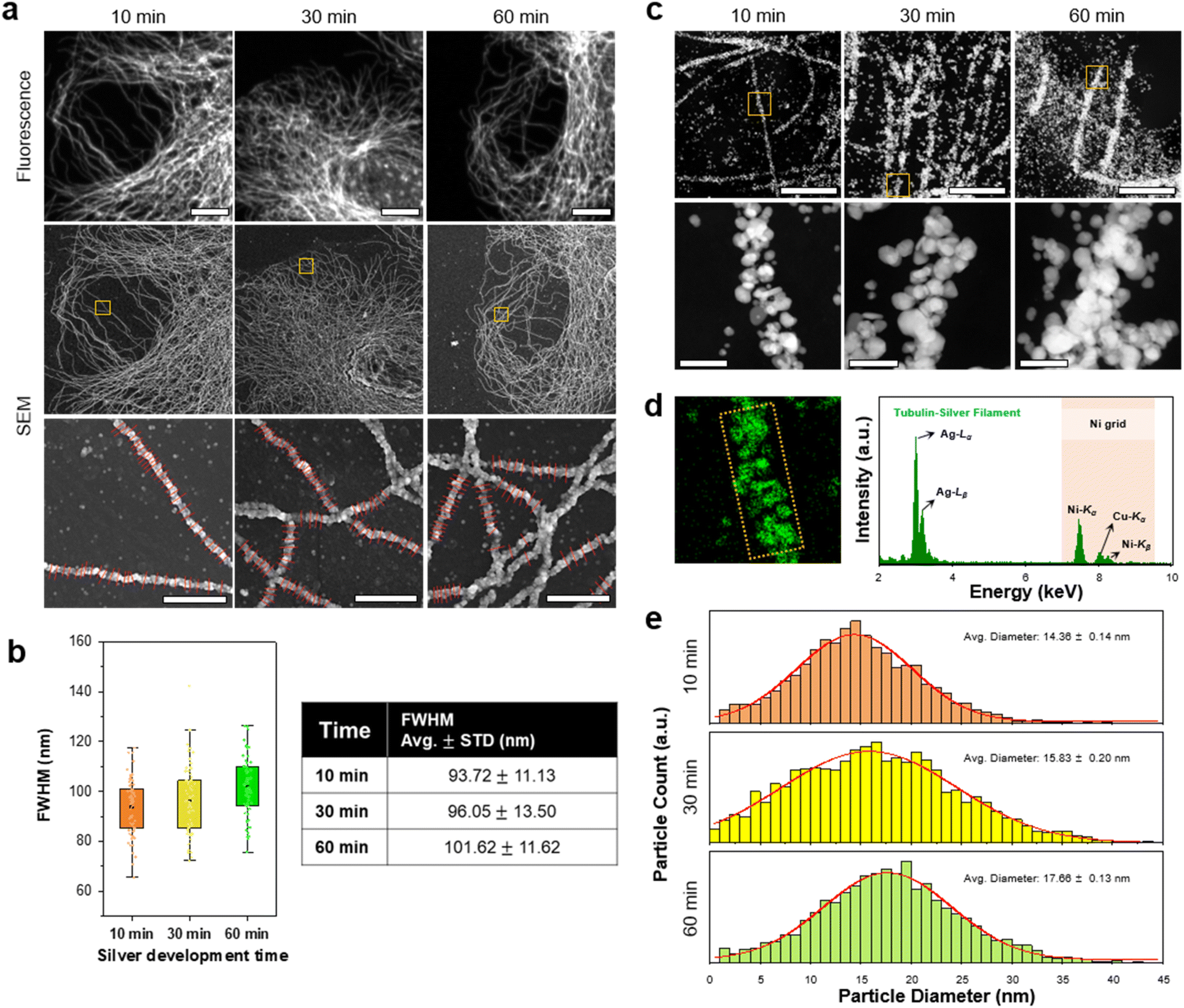 | ||
| Fig. 3 Change in silver structures and particle size according to in situ silver development time. (a) FM and SEM images of β-tubulin labeled BS-C-1 cells according to silver development time. Magnified SEM images of the yellow boxed regions in each sample with red lines at the bottom images for the FWHM value calculation. (b) FWHM comparison against silver development time. The points in (b) were obtained through 30 measurements, each from the image shown. (c) Scanning transmission electron microscopy (STEM) images of AgNPs labeled β-tubulin. Magnified STEM images of the yellow boxed regions in each sample. The section thickness of the resin-embedded samples was 300 nm. (d) Energy-dispersive X-ray spectroscopy (EDS) map from the same region in a magnified 10 min STEM image. The spectrum was obtained from the yellow boxed region in the EDS map. (e) Size distributions of AgNPs according to silver development time. Scale bar: (a) 10 μm, 1 μm; (c) 1 μm, 100 nm. | ||
We then determined the resolution of DecoM. First, we attempted to determine the resolution of DecoM from the SEM images using Fourier ring correlation (FRC) analysis (ESI Fig. 16†). The FRC analysis has been widely used to measure the resolution of single-molecule localization microscopy (SMLM).38 The resolution measured by the FRC analysis of the SEM image of DecoM-processed cultured cells was 15.85 nm. This value does not accurately represent the resolution of DecoM since the influence of the probe size is not considered in this calculation. In DecoM, unlike SMLM, the size of the probes, which comprise antibodies and silver particles, is greater than the resolution of microscopy, which is SEM. Thus, the minimal distance between the two structures that could be resolved with DecoM depends on the location of probes relative to target proteins. As the resolution of DecoM depends on how the probes are positioned, we estimated it for the most conservative case, in which antibodies and silver nanoparticles are positioned between two target structures (ESI Fig. 17†). In such a case, the separation of the two silver nanoparticles would be apparent in SEM imaging if the distance between the surfaces of the two silver nanoparticles was larger than the resolution of the SEM, which is 15.85 nm. Then, the distance between the two target proteins would be 70.83 nm (=(13.13![[thin space (1/6-em)]](https://www.rsc.org/images/entities/char_2009.gif) 39 + 14.36) × 2 + 15.85), given that the size of the antibody complex is 13.13 nm and that of the silver nanoparticles is 14.36 nm.
39 + 14.36) × 2 + 15.85), given that the size of the antibody complex is 13.13 nm and that of the silver nanoparticles is 14.36 nm.
Multiplexed imaging strategy and colocalization of proteins. Next, we demonstrated the multiplexed imaging of two proteins through DecoM (Fig. 4a, and ESI Fig. 18 and 19;† see the ‘Image registration and reconstruction of multiplexed DecoM’ in methods section). First, we labeled tubulin and vimentin with primary and secondary antibodies bearing fluorophores and AuNPs. The secondary antibodies used for labeling tubulin and vimentin bore different fluorophores. Then, dual-color FM images were acquired using diffraction-limited FM. Following FM imaging, silver was developed inside the cells. In the brightfield and SEM images, both tubulin and vimentin filaments were clearly shown, but the identities of each structure were not identifiable (Fig. 4b). We then used the SEM image as a mask against the FM images to improve the resolution of the FM images and to identify the silver structures in the SEM image (Fig. 4c). The identities of the two silver structures shown in the SEM were identified as either microtubules or vimentin filaments, as shown in Fig. 4d. In addition, considering the resolution of DecoM, vimentin filaments appeared as on strand in fluorescence, but they are expected to consist of two filaments through SEM. Interestingly, the widths of the silver nanofilaments were different between microtubules and vimentin filaments due to the difference in their diameters, which were 25 nm for microtubules and 10 nm for vimentin filaments,40 as shown in Fig. 4e. Using this approach, we demonstrated a three-color multiplexed imaging of three proteins: tubulins, TOM20, which is a mitochondrial protein, and a clathrin heavy chain (ESI Fig. 20†).
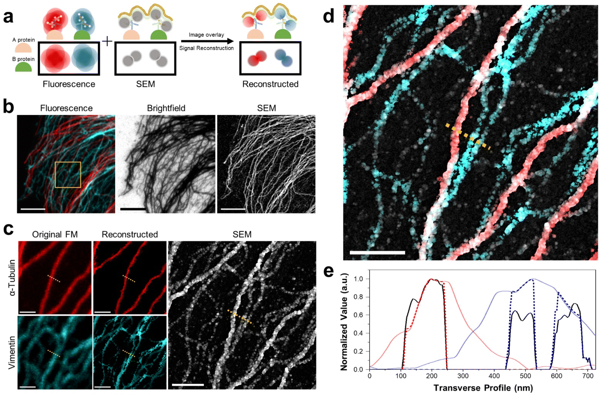 | ||
| Fig. 4 Dual-color DecoM images of cytoskeleton proteins. (a) Schematic of dual-color DecoM. (b) Corresponding images labeled with anti-α-tubulin (red) and vimentin (cyan) in the BS-C-1 cells by FM, brightfield microscopy, and SEM. (c) Magnified original and reconstructed FM images and SEM image from the yellow-boxed region in (b). (d) Overlay image of reconstructed dual-color fluorescence images and SEM image in (c). (e) The signal profiles along the yellow dotted line in (c and d) (red: α-tubulin, cyan: vimentin; solid line: original fluorescent signal, dashed line: reconstructed signal, black: reconstructed SEM signal). Scale bar: (b) 5 μm, (c) 1 μm, (d) 1 μm. | ||
Use of DecoM to study nanoscale changes in microtubules
Next, we investigated the possibility of applying DecoM to study the detailed structural changes associated with disease conditions. Microtubule-severing enzymes utilize adenosine triphosphate (ATP) hydrolysis to fragment microtubules and are associated with hereditary spastic paraplegia and microcephaly.41–43 Spastin, one of the microtubule-severing proteins, breaks and destabilizes microtubules inside cells, and its mutations are known to cause hereditary spastic paraplegias.44,45 In previous studies, FM has been used to examine microtubule fragmentation caused by spastin by observing changes in microtubules labeled with fluorescent signal.46,47 Due to the diffraction limit of light, observing microtubules severed by FM with high resolution in cells, especially in a region where microtubules form a dense network, has been challenging. Therefore, severed microtubules have been observed where the microtubules are sparse in cells or in an in vitro setting of immobilized microtubules via FM48 or TEM.49,50 Obviously, more information and insights would be provided if we could examine microtubule structures over an entire cell, including the periphery and central region.To test whether DecoM could visualize changes in microtubules caused by spastin, we overexpressed spastin in U2OS cells. Control and spastin-overexpressing cells were stained and imaged by applying the multiplexed DecoM imaging process. In the control cells, microtubules were continuous and formed organized arrays emerging from the microtubule-organizing center (Fig. 5a). By contrast, in spastin-overexpressing cells, microtubules became fragmented and disorganized (Fig. 5b and c). In the conventional FM images, we were able to detect the overall decrease in the fluorescent signal in the spastin-overexpressing cells compared with the control, but detailed structural changes in microtubules caused by spastin were not discernible. However, SEM imaging of the DecoM-processed specimens clearly revealed structural differences between the microtubule architecture in the spastin-expressing cells and the control cells. Owing to the multiplexed imaging capability of DecoM, spastin overexpression in cells could also be detected. In many cases, a high level of spastin expression was observed where microtubules were absent or fragmented (Fig. 5c), consistent with the reported function of spastin as a microtubule-severing protein. We also found higher background signals and/or more puncta inside the cytoplasm in spastin-overexpressing cells compared with control cells in the SEM images, as shown in Fig. 5c. Such background signals are likely to be attributed to the removal of tubulin monomers from microtubule polymers by the severing activity of spastin.
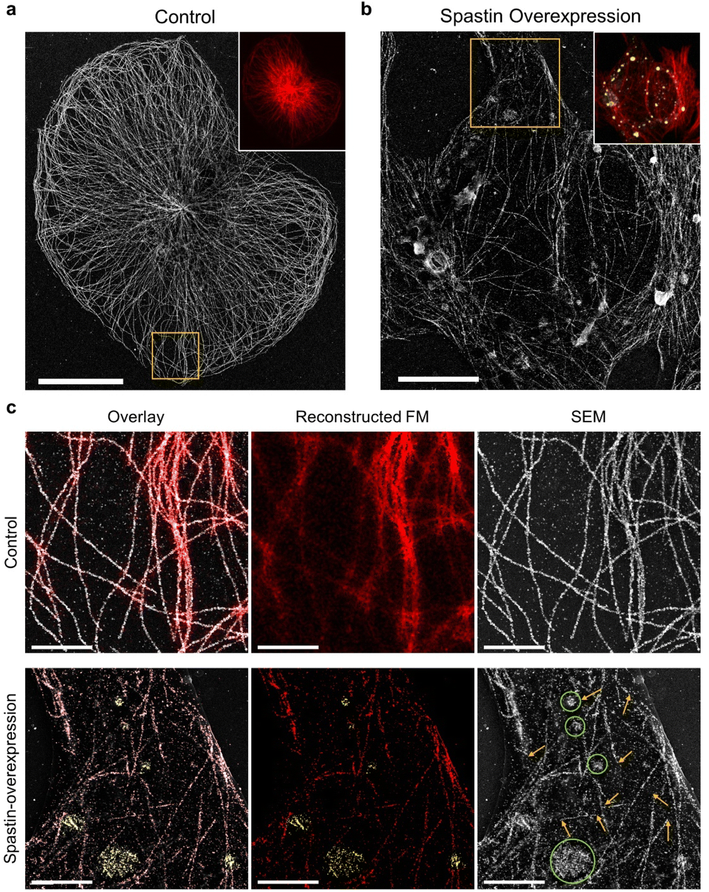 | ||
| Fig. 5 DecoM images of severed microtubules in a spastin-overexpressing cell. (a) SEM image of a normal U2OS cell labeled with anti-β-tubulin antibodies. (Inset fluorescence image from the same position as the SEM image). (b) SEM image of a spastin-overexpressing U2OS cell labeled with anti-β-tubulin antibodies and anti-FLAG (spastin) antibodies. Inset fluorescence image (red: β-tubulin, yellow: FLAG-tagged spastin) from the same position as SEM image. (c) Magnified images of the yellow-boxed regions in (a) and (b). Overlay images of reconstructed FM images and SEM images. (Overlay: red: β-tubulin; yellow: FLAG-tagged spastin. SEM: yellow arrows, regions of severed microtubules; green circles, locations of spastin in regions devoid of continuous microtubule structures). Scale bar. (a) 20 μm, (b) 10 μm, (c) 3 μm. | ||
We also examined changes in microtubules caused by another severing protein, katanin. In fibroblasts and cultured neurons, the overexpression of the enzymatic subunit of katanin, Kp60, induced a marked loss of microtubules.51,52 However, in other cells, such as U2OS and HeLa cells, the effect has not been obvious, presumably due to the cell-type-specific biochemical properties of microtubules.53 With conventional FM imaging in U2OS cells, neither changes in the fluorescent intensity of tubulin nor structural defects have been detected.53 Through SEM imaging of DecoM-processed specimens, we detected tubulin monomers formed as a result of microtubule fragmentation in U2OS cells overexpressing katanin p60 (ESI Fig. 21†). In the transfected cells, we found scattered tubulin monomers around the cells with SEM imaging. Furthermore, we observed the death of katanin p60-overexpressing cells surrounded by the scattered tubulin monomer in brightfield images (ESI Fig. 22†), suggesting that the overexpression of the severing protein may cause cell death.
We believe that the multiplexed imaging capability of DecoM demonstrated here would be highly useful for studying nanoscale changes in cytoskeletons. Microtubule dysfunction has been inferred in many cilia-related disorders, commonly referred to as ciliopathies,54 and perturbation of microtubule structures and functions is associated with some neurological conditions,55 such as schizophrenia56 and Alzheimer's disease.57 Modifications of platelet microtubules have been linked to bleeding disorders,58 and defects in cell cycle progression mediated by microtubules are well known to cause cancer.59 Changes in vimentin, one of the intermediate filaments (IF), with IF-associated proteins, such as plectin and ankyrin are indicators of many cancers.60,61 We thus expect DecoM to be applied for the investigation of nanoscale details of cytoskeleton structures in a wide range of cytoskeleton-related diseases without specialized equipment or complicated procedures.
DecoM combined with expansion microscopy (ExM) for brightfield microscopy
We then aimed to enhance the resolution of BF microscopy by combining DecoM with ExM (Deco-ExM). On BF microscopy, AgNPs generated from AuNPs exhibited a high light contrast, as shown in ESI Fig. 1.† We first examined whether such a high light contrast could be achieved in a thick mouse brain slice. A mouse brain slice with a thickness of 150 μm was stained with a primary antibody against MAP2 and Fab fragments of secondary antibodies containing AuNPs with a diameter of 1.4 nm, followed by silver development. After silver development, the color of the brain slice turned dark brown due to the light absorption of dense dendrites in the slice, as shown in Fig. 6b-i. However, it was challenging to resolve individual dendrites due to the high level of light absorption of the brain slice (Fig. 6c-i; see ESI Fig. 23† for the light absorption of a thick brain slice without any silver development). We then tested an alternative approach. A brain slice was stained with the same primary antibody and secondary antibody. Subsequently, the brain slice was treated with 6-((acryloyl)amino)hexanoic acid (AcX), which makes all proteins gel-anchorable, embedded in a swellable hydrogel, and digested with proteinase K. The digested brain slice was then subjected to silver development and expanded four-fold in DW. After expansion, the strong light absorption of the brain slice on BF microscopy was no longer observed, as shown in Fig. 6c-ii. Proteinase treatment, which is an essential step for the uniform expansion of specimens, might remove all light-absorbing proteins from the brain slices, reducing background light absorption. In addition, the volumetric dilution of molecules inside the brain slice also reduced background light absorption. However, the contrast of the silver structures was not high enough for the clear visualization of the labeled structures. Such low light absorption of the silver structures could be attributed to volumetric dilution and digestion. The number density of AgNPs in a given voxel after expansion would be 64-fold (=43) lower than that of the unexpanded specimen. More importantly, during the proteinase digestion process, antibodies were also digested and the AuNPs of the antibodies were washed away from the hydrogel. Due to these two effects, the number density of AuNPs decreased, resulting in the low contrast of the labeled structures. As ExM obtains a greater resolution by volumetric expansion, a reduction in label density was unavoidable. Thus, we attempted to diminish the second effect, which was the decrease in the number density of AuNP seeds caused by digestion.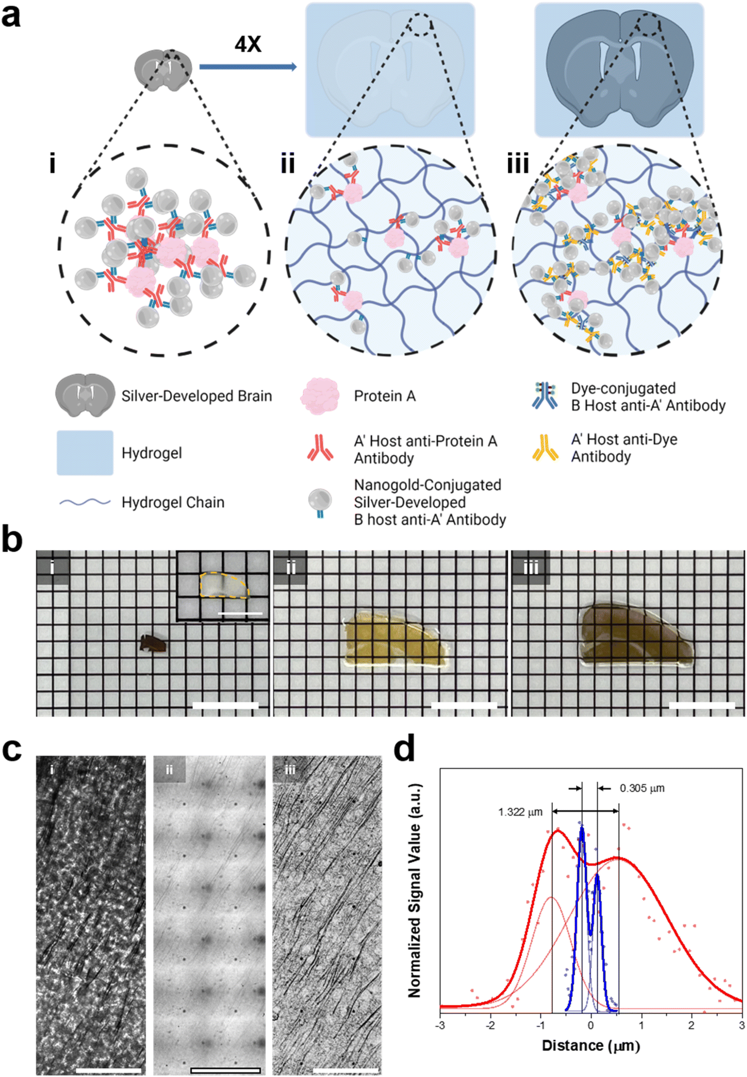 | ||
| Fig. 6 In situ silver development on a brain slice and hydrogel-tissue composites. (a) Illustration of (i) a silver-developed brain slice, (ii) ExM proceeded, and silver-developed hydrogel-tissue composite, and (iii) Deco-ExM proceeded hydrogel-tissue composite. (b) Photographs of the silver-developed brain slice and hydrogel-tissue composites according to the Roman numerals in (a). (Inset: photograph of the fixed brain slice) (c) brightfield images of MAP-2 protein labeled tissue and tissue-hydrogel composites according to the Roman numerals (d) the signal profiles of the brightfield signal with the smallest distance among R-square values greater than 0.9 in ESI Fig. 24.† (red dot: silver-developed sample, blue dot: Deco-ExM proceeded sample, solid lines: double Gaussian fits). Scale bar: (b) 8 mm (inset: 4 mm), and (c) 10 μm. | ||
We tried an alternative approach that introduced AuNP-conjugated antibodies after expansion. A mouse brain slice was stained with the same primary antibody and a secondary antibody conjugated with Alexa Fluor 488. The brain slice was treated with AcX, embedded in a swellable hydrogel, treated with proteinase K, and expanded four-fold in DW. Then, the expanded hydrogel was stained with a primary antibody against Alexa Fluor 488 and Fab fragments of secondary antibodies bearing AuNPs with a diameter of 1.4 nm, followed by silver development. In this process, AuNPs were introduced to the expanded specimen after the digestion process, avoiding a decrease in the number density of AuNPs in the specimen caused by digestion. In this process, gel-anchored Alexa Fluor 488 might also be washed away from the hydrogel during the digestion process. However, the remaining Alexa Fluor 488 might be labeled with multiple primary antibodies against Alexa Fluor 488 and multiple Fab fragments of a secondary antibody bearing AuNPs. Through this process, the number density of AuNPs in the expanded hydrogel was amplified. After the silver development, dendrites were clearly visible, as shown in Fig. 6c-iii. The extended specimen obtained by this post-gelation AuNP staining and silver development process (Fig. 6b-iii) had a darker color than the specimen prepared by the pre-gelation AuNP staining technique (Fig. 6b-ii). This color difference suggests that the post-gelation AuNP and silver development process produced a specimen with more AuNP seeds. We then quantified the resolution enhancements following the expansion. Before the expansion, the smallest distance that could be resolved between two adjacent dendrites was around 1.322 μm. However, after extension, two dendrites separated by 0.305 μm were resolved with about a four-fold improvement in resolution (Fig. 6d and ESI Fig. 24†). In addition, this value indicates that sub-micron resolution could be obtained through Deco-ExM.
Conclusions
In this work, we presented a series of sample preparation and staining protocol employing antibodies bearing 1.4 nm AuNPs and silver development to enable multiplexed imaging with SEM and sub-micron resolution BF microscopy. We first showed that labeling proteins inside cells with antibodies bearing 1.4 nm AuNPs, developing silver onto the AuNPs, and simply drying the cells yielded strong electron signals on SEM. Using STORM, we showed that the distortion of structures during the drying process was negligible, especially in the peripheral region of the cells. Around the nucleus of the cells, larger distortion was observed, but simple buffer exchange to HMDS greatly improved the structural distortion around the nucleus. STORM imaging also confirmed that the nanoscale details of the structures, such as the local bending of microtubules, were conserved. Such a high level of structural information preservation and low structural distortion enabled multiplexed imaging using SEM. We then determined the resolution of DecoM. We measured the resolution of our approach, which was 70.83 nm. A higher resolution would be achieved if higher SEM magnification was used in the SEM imaging. As the resolution of DecoM is greater than that of diffraction-limited confocal microscopy and SIM, DecoM would be highly useful for biologists to observe sub-100 nm structures. We applied a similar approach to BF microscopy to improve the resolution. Since the demonstration of ExM in 2015, it has not been applied to BF microscopy. We first showed that the light absorption of thick tissue slices can be greatly reduced after expansion. We then showed that the application of AuNPs and silver development needed to be performed after expansion to achieve a high light contrast. Through these studies, we achieved sub-micron resolution imaging with BF microscopy.The molecular-specific SEM imaging reported in this study could be a beneficial tool for researchers who need resolution above the diffraction limit of light but lack access to super-resolution fluorescence microscopy. Super-resolution fluorescence microscopy techniques, such as STORM and stimulated emission depletion (STED) microscopy, are not extensively used in most biological research and diagnostics because they require a specialized instrument and knowledge of fluorophore blinking or depletion. DecoM imaging, as demonstrated in this work, requires only standard SEM and readily accessible chemicals. SEM is more generally available and accessible in research institutes than STORM or STED since it is widely employed not just for biological science study but also for material science research. Furthermore, no sophisticated sample preparation is required, which is generally necessary for the SEM imaging of intracellular proteins. In this study, we employed DecoM to image microtubule fragmentation in cultivated cells, which is impossible to image with diffraction-limited FM.
In a similar vein, the sub-micron resolution BF microscopy demonstrated in this study would greatly expand the application of BF microscopy. Among BF microscopy, FM, and EM, BF microscopy is the most widely available in research laboratories and hospitals. However, due to the considerable light absorption of thick tissue slices, the use of BF microscopy has been primarily restricted to thin tissue slices. Additionally, its resolution is limited to 1 to 2 microns, rendering it unsuitable for imaging submicron structures. We demonstrated that by combining DecoM with ExM (Deco-ExM), the resolution of BF microscopy could be increased beyond one micron.
Methods
Cell culture and transfection of U2OS cells
BS-C-1 and U2OS cells were obtained from the Korean Cell Line Bank. BS-C-1 cells were plated on CultureWell removable chambered coverglasses (16 well, Grace Bio-Labs) or confocal dishes (20 mm hole, SPL) at a density of 2.5 × 10⁴ cells per well and cultured in MEM supplemented with 10% heat inactivated fetal bovine serum (FBS, Gibco), 1% penicillin-streptomycin (Gibco), and 1% sodium pyruvate (Gibco). U2OS cells were plated on circular glass coverslips (12 mm, EMS) coated with 10 μg ml−1 poly-D-lysine (Sigma) at a density of 5 × 10⁴ cells per well (24-well plate, SPL) and cultured in RPMI (Hyclone) supplemented with 10% FBS and, 1% penicillin-streptomycin. For overexpression in U2OS cells, plasmid containing human spastin (SWISS-PROT entry: Q9UBP0) or human katanin p60 (SWISS-PROT entry: O75449) were obtained from OriGene Technologies, Inc (ESI Table 1†). Polyethylenimine (Polysciences) was used for transient transfections according to the manufacturer's protocol. Briefly, cells were seeded and cultured in penicillin/streptomycin-free media for 12 h prior to transfection. PEI-DNA (Flag and Myc tagged spastin or katanin p60) transfection complex was incubated in Opti-MEM reduced serum medium at RT for 10 min. PEI-DNA transfection complex was then added to each well (drop-wise), while gently swirling the culture plate. Transfected cells were fixed after 12–24 h. All cells were cultured at 37 °C in a humidified incubator with 5% CO2.Fixation and immunostaining of cells
For staining of tubulin, BS-C-1 cells were first washed briefly with 1X phosphate-buffered saline (PBS, Invitrogen) three times. Then cells were extracted for 1 min with cytoskeleton extraction buffer62(0.1 M 1,4-piperazinediethanesulfonic acid (PIPES, Sigma), 1 mM ethylene glycol-bis(2-aminoethylether)-N,N,N′,N′-tetraacetic acid (EGTA, Sigma), 200 mM sodium hydroxide (NaOH, Sigma), 1 mM magnesium chloride (MgCl2, Sigma), 0.2% Triton X-100 (Sigma), pH 7). The extracted cells were fixed with tubulin fixation solution (3% paraformaldehyde (PFA, EMS), 0.1% glutaraldehyde (GA, EMS) in 1X PBS) for 10 min, followed by a reduction with 0.1% sodium borohydride (NaBH4, Sigma) in 1X PBS for 7 min, and then rinsed with 0.1 M glycine (Sigma) in 1X PBS three times. For staining of vimentin with tubulin in BS-C-1 cells, the cells were fixed with 4% PFA in 1X PBS for 10 min and rinsed with 1X PBS three times for 5 min each. U2OS cells were simultaneously fixed and detergent-extracted in a solution containing prewarmed 4% PFA, 0.15% GA, and 0.2% Triton X-100 in 1X PBS at 37 °C for 20 min. For the imaging, the fixed cells well incubated for 2 h in a blocking buffer (5% normal goat serum (JacksonImmunoResearch), 0.2% Triton X-100 in 1X PBS). The cells were then stained for 30 min with primary antibodies. After the primary antibody incubation, the cells were washed three times with the blocking buffer for 5 min each. Following the primary antibody staining, the cells were stained for 30 min with FluoroNanogold (Fab' product, Nanoprobes) as secondary antibodies at a Fab' concentration of 2 μg ml−1 diluted in the blocking buffer and then washed with the blocking buffer, 0.2% Triton X-100 in 1X PBS, and 1X PBS sequentially for 5 min each. All antibodies were obtained from commercial suppliers, and detailed information is listed in ESI Table 1.†Confocal microscopy and brightfield imaging
Confocal imaging was performed on an Andor spinning disk confocal microscope (Dragonfly, Oxford Instruments) or a scanning confocal microscope (C2 plus, Nikon) through an inverted microscopy (Ti2-E, Nikon) with a 40 × 1.15 NA water-immersion objective. Brightfield images were obtained by a brightfield imaging filter mode on Fusion software.STORM imaging
STORM imaging was performed with a custom-built STORM setup, which consists of an inverted microscope (Ti2-U, Nikon), a 100 × 1.49 NA oil immersion objective lens (CFI SR HP Apo TIRF, Nikon), an electron-multiplying charge-coupled device (EMCCD) camera (iXon Ultra 888, Andor) and lasers. For one-color STORM imaging, 120 mW 647 nm laser (OBIS, Coherent) and 0.1–1 mW 405 nm laser (OBIS, Coherent) were used for photo-switching and re-activation, respectively. Output fluorescence emission from the sample was filtered using a bandpass emission filter (LF408/488/561/635 B, Semrock) and imaged onto an EMCCD camera at a frame rate of 60 Hz. Autofocus system (ASI) was used to maintain a constant focal plane of the sample during STORM data acquisition. During the STORM imaging, the samples were immersed in STORM imaging buffer (100 mM mercaptoethylamine (MEA, Sigma), 5% glucose (w/v), and oxygen scavenging enzymes (0.5 mg ml−1 glucose oxidase (Sigma) and 38 μg ml−1 catalase (Sigma) in 1X PBS) at pH 8.5). To reconstruct the STORM image, centroid positions of individual fluorophores in the STORM movie were first determined by fitting each point spread function with the 2D Gaussian function, and then the centroid coordinates were collected. After the drift-correction, localizations were rendered for the final STORM image.In situ silver development and ambient condition drying of cells
The cells were post-fixed with 1% GA in 1X PBS for 10 min, and then washed with distilled water three times for 5 min each. The post-fixed cells were washed with 0.02 M sodium citrate (Sigma) three times for 5 min each and in situ silver development was performed with HQ silver (Nanoprobes) according to the manufacturer's protocol, followed by rinse with DW three times for 1 min. For ambient condition dehydration, the cover glasses were detached from CultureWell and confocal dish (circular coverslips were used as itself), and then remained excess DW on the glass was removed using wipers carefully, followed by air-blowing using dust blower. Dehydrated cells were stored in a desiccator until conductive metal coating.Hexamethyldisilazane (HMDS) dehydration and critical point drying (CPD) of cells
First, the cells were dehydrated through a graded ethanol series of 50, 60, 70, 80, 90, and 100% twice for 10 min each. After ethanol dehydration of the cells, HMDS (Sigma) dehydration was conducted following HMDS drying protocol.63 The HMDS drying protocol is divided into primary and secondary procedures. In the primary HMDS procedure, the ethanol-dehydrated cells were incubated in 100% ethanol solution by increasing the HMDS concentration by 10% for 5 min each from 10% to 100%. After the primary HMDS procedure, the cells were washed with 100% HMDS solution for 20 min twice followed by evaporation under ambient conditions. For CPD, after ethanol dehydration, the cells were dehydrated using a critical point dryer (LEICA EM CPD300). CPD was performed at the Avison BioMedical Research Center.SEM imaging
For SEM imaging, the dehydrated cells were coated with platinum using a sputter coater (SCD-500, BAL-TEC) or with osmium using osmium plasma coater (HPC-1SW, Vacuum Device). SEM imaging was performed on scanning electron microscope (S4800, Hitachi). Regions of interest in cells were imaged using a SE detector, with accelerating voltages of 10 kV for SEM. SEM imaging using BSE detector was performed on SEM (SU8230, Hitachi) of KARA (KAIST Analysis center for Research Advancement).Registration of optical and SEM images
For overlaying optical and SEM images, first, volumetric confocal images of the cells were projected using maximum intensity projection or color-code through ImageJ software (Image > Hyperstacks > Temporal Color Code > Rainbow RGB). Brightfield images were signal-inverted for registering with projected confocal images. Then, optical images are resized against the same region of SEM images, followed by registration manually or through ‘Register Virtual Stack Slices’ plugins in ImageJ (Plugins > Registration > Register Virtual Stack Slices, Registration model: Elastic, bUnwarpJ64 splines), and then registered images were overlaid for correlative analysis.Image reconstruction and correlative analysis
After the registration of optical microscopy (FM and STORM) and SEM images written above, using MATLAB software, we first subtracted the background signal from both images, after which pixels with non-zero values in both images were selected. Subsequently, in the registered optical and SEM images, the pixel values of the pixels that had not been selected were adjusted to 0. The selected pixels' pixel values remained unchanged. The correlative analysis of the adjusted images was conducted using the ImageJ ‘Coloc 2’ plugin.Ultramicrotome sectioning and STEM imaging
For analysis using STEM imaging, silver developed cells were resin embedded using epoxy resin embedding kits (Embed-812, EMS). First, the cells were dehydrated through a graded ethanol series of 30, 40, 50, 60, 70, 80, 90, 95, and 100% for 15 min each, followed by a transition in 99.5% propylene oxide (EMS) for 20 min. Transient cells by propylene oxide were incubated in propylene oxide-resin solutions mixed in 2:1, 1:1, and 1:2 ratio for 1 h each, and then the cells were incubated in 100% resin for overnight at room temperature, followed by polymerization of resin at 40 °C in a convection oven for 48 h. The resin blocks were trimmed and sectioned in 300 nm thickness with ultramicrotome (EM UC7, Leica), and the sections were collected on nickel grids. The ultramicrotome sectioning was carried out in the EM & Histology Core Facility, at the BioMedical Research Center, Korea Advanced Institute of Science and Technology. STEM images were acquired in KARA (KAIST Analysis center for Research Advancement) with a transmission electron microscope (Talos F200X, Thermo Fisher Scientific) at 300 kV with HAADF detector. For analysis of silver nanoparticles size, STEM images were processed with FFT-Bandpass filter and threshold adjustment, followed by binary and watershed process through ImageJ software. Silver nanoparticles in the field of view of each image were counted by the function of ‘Analyze particles’ in ImageJ with exclusion on edges. EDS mapping of silver particles in sections was obtained by acquisition of X-ray signals with 4 windowless SDD EDS system (Super X, Thermo Fisher Scientific). EDS maps ere low-pass filtered using Bruker ESPRIT software after the reduction of background noise for better visualization.
Fourier ring correlation-based resolution calculation
We applied an open Fourier ring correlation (FRC) Python code (https://github.com/prabhatkc/siFRC)65 to consecutive SEM images acquired from the same area with a magnification of 25 kX and an accelerating voltage of 10 kV. Three consecutive SEM image sets were obtained from different cells and analyzed using the FRC code.Image registration and reconstruction of multiplexed DecoM
To register multiplexed FM and SEM image, we first merged each FM channel into a single channel, followed by registration with the SEM image through bUnwarpJ plugins (Source Image: SEM image, Target Image: FM image, Registration mode: Mono) in ImageJ. Then, after executing the bUnwarpJ plugin in ImageJ, we applied the deformation vector information obtained from registration through ‘Load Elastic Transformation’ in the I/O Menu to the original FM image of each channel. After the registration of all images, background signal subtraction and pixel extraction were performed on each image through MATLAB software as described in the ‘Image reconstruction and correlative analysis’ Method section.Mouse brain perfusion and slicing
The following procedures involving animals were approved by the Korea Advanced Institute of Science and Technology Institutional Animal Care and Use Committee (KAIST-IACUC). C57BL/6J mice aged 8–14 weeks were used. Mice were maintained in a specific pathogen-free facility of KAIST Laboratory Animal Resource Center. Mice were anesthetized with isoflurane and transcardially perfused with ice-cold 4% PFA in 1X PBS. Brains were extracted and incubated in the same solution at 4 °C for 2 h and sliced into 150 μm-thick slices on a vibratome (Leica VT1000S). The slices were stored in 0.1 M glycine and 0.01% sodium azide in 1X PBS at 4 °C before use.Staining, ExM processing, and post-gel staining of brain slice
For staining, the mouse brain slices were incubated for 2 h in a blocking buffer. The brain slices were then stained for overnight with primary antibodies. After the primary antibody incubation, the brain slices were washed three times with the blocking buffer for 30 min each. Following the primary antibody staining, the brain slices were stained for overnight with Nanogold Antibody Conjugates (Fab' product, Nanoprobes) as secondary antibodies at a Fab' concentration of 2 μg ml−1 diluted in the blocking buffer or fluorophore conjugated secondary antibodies (ThermoFisher) at an IgG concentration of 2 μg ml−1 diluted in the blocking buffer and then washed with the blocking buffer, 0.2% Triton X-100 in 1X PBS (PBST), and 1X PBS sequentially for 30 min each. For the brain slices, the slices were first incubated with a monomer solution (7.5% (w/w) sodium acrylate (Ambeed), 2.5% (w/w) acrylamide (Sigma), 0.15% (w/w) N,N′-methylenebis(acrylamide) (Sigma), 2 M NaCl, 0.2% (w/w) ammonium persulfate (APS) (Sigma), 0.2% (w/w) tetramethylethylenediamine (TEMED) (Sigma), 4-hydroxy-2,2,6,6-tetramethylethylpiperidin-1-oxyl (H-TEMPO), 1X PBS) at 4 °C twice for 30 min each time and then incubated at 37 °C for 1.5 h for gelation. After gelation, the gels on the cover glasses were treated with proteinase K (800 units per mL) (New England Bio, NEB) diluted at 1:100 in a digestion buffer (25 mM EDTA (ThermoFisher), 50 mM Tris–HCl (pH 8.0) (Sigma), 0.5% Triton X-100, 1 M NaCl) at RT overnight. After digestion, the digested gels were washed with deionized water multiple times. The gels were washed until their size remained unchanged. For DecoExM, fluorophore conjugated secondary antibodies stained gels were incubated twice for 30 min each time with PBST. The gels were then stained for overnight at 4 °C with anti-fluorophore antibodies (ThermoFisher) at an IgG concentration of 10 μg ml−1 diluted in PBST and then washed with three times for 30 min each. Following the anti-fluorophore antibody staining, the gels stained for overnight with Nanogold Antibody Conjugates at a Fab' concentration of 2 μg ml−1 diluted in PBST and then washed with PBST twice, and 1X PBS once for 30 min. All antibodies were obtained from commercial suppliers, and detailed information is listed in ESI Table 1.†
In situ silver development of brain slice and hydrogel composites
For brain slices, slices were post-fixed with 1% GA in 1X PBS for 15 min, and then washed with distilled water three times for 30 min each. The post-fixed slices were washed with 0.02 M sodium citrate three times for 30 min each and in situ silver development was performed with HQ silver for 30 min, followed by wash with 0.02 M sodium citrate three times and DW three times for 30 min. For hydrogel–brain composites, gels were washed with 0.02 M sodium citrate three times for 30 min each and in situ silver development was performed with HQ silver for 30 min, followed by wash with 0.02 M sodium citrate three times and DW three times for 30 min.Author contributions
D.-H. Song and J.-B. Chang designed the study. D.-H. Song, C. W. Song characterized with electron microscopy. D.-H. Song, J. Chung, and D. Kim performed fluorescence microscopy and stochastic optical reconstruction microscopy. D.-H. Song and Y. Hur performed ultramicrotome sectioning for transmission electron microscopy. D.-H. Song and H. Kim designed the code for the reconstruction of scanning electron microscopy and fluorescence microscopy images, and also performed FRC calculation. D.-H. Song, E.-H. Jang, and E.-M. Hur conducted the experiment related with microtubule-severing proteins. D.-H Song conducted the experiment of expansion microscopy. D.-H. Song and J.-B. Chang wrote the manuscript with inputs and feedback from all authors.Conflicts of interest
The authors declare no competing financial interest.Acknowledgements
This research was supported by Basic Science Research Program through the National Research Foundation of Korea (NRF) funded by the Ministry of Education (NRF-2019R1F1A1063145, NRF-2021M3E5D9021369, NRF-2021R1C1C1006642) and the Brain Research Program through the National Research Foundation of Korea (NRF) funded by the Ministry of Science, ICT & Future Planning (NRF-2017M3C7A1043841, NRF-2021M3A9I4026318). This research was also supported by the KAIST (N11210176, Venture Research Program for Master's and PhD Students in the College of Engineering) and the National Convergence Research of Scientific Challenges through the National Research Foundation of Korea (NRF) funded by Ministry of Science and ICT (NRF-2020M3F7A1094300). Also, this work was supported by the National Research Foundation of Korea (NRF) grant funded by the Korea government (MSIT) (NRF-2021R1C1C1006700) and the POSCO Cheongam Foundation (Fellowship to D. K.).References
- S. Gopal, C. Chiappini, J. P. K. Armstrong, Q. Chen, A. Serio, C. C. Hsu, C. Meinert, T. J. Klein, D. W. Hutmacher, S. Rothery and M. M. Stevens, Adv. Mater., 2019, 31, 1900488 CrossRef PubMed.
- I. D. Odell and D. Cook, J. Invest. Dermatol., 2013, 133, 1–4 CrossRef PubMed.
- M. De Waele, W. Renmans, E. Segers, K. Jochmans and B. Van Camp, J. Histochem. Cytochem., 1988, 36, 679–683 CrossRef CAS PubMed.
- G. Wang and N. Fang, Detecting and Tracking Nonfluorescent Nanoparticle Probes in Live Cells, Elsevier Inc., 1st edn, 2012, vol. 504 Search PubMed.
- E. Abbe, Arch. Mikrosk. Anat., 1873, 9, 413–468 CrossRef.
- F. Sigmund, S. Pettinger, M. Kube, F. Schneider, M. Schifferer, S. Schneider, M. V. Efremova, J. Pujol-Martí, M. Aichler, A. Walch, T. Misgeld, H. DIetz and G. G. Westmeyer, ACS Nano, 2019, 13, 8114–8123 CrossRef CAS PubMed.
- P. Webster, H. Schwarz and G. Griffiths, Methods Cell Biol., 2008, 88, 45–58 CAS.
- D. P. Hoffman, G. Shtengel, C. S. Xu, K. R. Campbell, M. Freeman, L. Wang, D. E. Milkie, H. A. Pasolli, N. Iyer, J. A. Bogovic, D. R. Stabley, A. Shirinifard, S. Pang, D. Peale, K. Schaefer, W. Pomp, C. L. Chang, J. Lippincott-Schwartz, T. Kirchhausen, D. J. Solecki, E. Betzig and H. F. Hess, Science, 2020, 367, 6475 CrossRef PubMed.
- B. Huang, H. Babcock and X. Zhuang, Cell, 2010, 143, 1047–1058 CrossRef CAS PubMed.
- B. Huang, M. Bates and X. Zhuang, Annu. Rev. Biochem., 2009, 78, 993–1016 CrossRef CAS PubMed.
- P. De Boer, J. P. Hoogenboom and B. N. G. Giepmans, Nat. Methods, 2015, 12, 503–513 CrossRef CAS PubMed.
- A. J. Koster and J. Klumperman, Nat. Rev. Mol. Cell Biol., 2003, SS6–SS10 Search PubMed.
- A. Löschberger, C. Franke, G. Krohne, S. van de Linde and M. Sauer, J. Cell Sci., 2014, 127, 4351–4355 Search PubMed.
- T. Ando, S. P. Bhamidimarri, N. Brending, H. Colin-York, L. Collinson, N. De Jonge, P. J. de Pablo, E. Debroye, C. Eggeling, C. Franck, M. Fritzsche, H. Gerritsen, B. N. G. Giepmans, K. Grunewald, J. Hofkens, J. P. Hoogenboom, K. P. F. Janssen, R. Kaufmann, J. Klumperman, N. Kurniawan, J. Kusch, N. Liv, V. Parekh, D. B. Peckys, F. Rehfeldt, D. C. Reutens, M. B. J. Roeffaers, T. Salditt, I. A. T. Schaap, U. S. Schwarz, P. Verkade, M. W. Vogel, R. Wagner, M. Winterhalter, H. Yuan and G. Zifarelli, J. Phys. D: Appl. Phys., 2018, 51, 443001 CrossRef PubMed.
- C. Fei, P. W. Tillberg and E. S. Boyden, Science, 2015, 347, 543–548 CrossRef PubMed.
- D. Goode and T. K. Maugel, J. Electron Microsc. Tech., 1987, 5, 263–273 CrossRef.
- M. J. Rust, M. Bates and X. Zhuang, Nat. Methods, 2006, 3, 793–795 CrossRef CAS PubMed.
- Y. Zhao, O. Bucur, H. Irshad, F. Chen, A. Weins, A. L. Stancu, E.-Y. Oh, M. DiStasio, V. Torous, B. Glass, I. E. Stillman, S. J. Schnitt, A. H. Beck and E. S. Boyden, Nat. Biotechnol., 2017, 35, 757–764 CrossRef CAS PubMed.
- T. Ku, J. Swaney, J.-Y. Park, A. Albanese, E. Murray, J. H. Cho, Y.-G. Park, V. Mangena, J. Chen and K. Chung, Nat. Biotechnol., 2016, 34, 973–981 CrossRef CAS PubMed.
- H. E. Park, D. Choi, J. S. Park, C. Sim, S. Park, S. Kang, H. Yim, M. Lee, J. Kim, J. Pac, K. Rhee, J. Lee, Y. Lee, Y. Lee and S. Y. Kim, Adv. Sci., 2019, 6, 1901673 CrossRef CAS PubMed.
- C. C. Yu, N. C. Barry, A. T. Wassie, A. Sinha, A. Bhattacharya, S. Asano, C. Zhang, F. Chen, O. Hobert, M. B. Goodman, G. Haspel and E. S. Boyden, Elife, 2020, 9, 1–78 Search PubMed.
- R. Gao, S. M. Asano, S. Upadhyayula, I. Pisarev, D. E. Milkie, T. L. Liu, V. Singh, A. Graves, G. H. Huynh, Y. Zhao, J. Bogovic, J. Colonell, C. M. Ott, C. Zugates, S. Tappan, A. Rodriguez, K. R. Mosaliganti, S. H. Sheu, H. A. Pasolli, S. Pang, C. S. Xu, S. G. Megason, H. Hess, J. Lippincott-Schwartz, A. Hantman, G. M. Rubin, T. Kirchhausen, S. Saalfeld, Y. Aso, E. S. Boyden and E. Betzig, Science, 2019, 363, 6424 Search PubMed.
- L. Freifeld, I. Odstrcil, D. Förster, A. Ramirez, J. A. Gagnon, O. Randlett, E. K. Costa, S. Asano, O. T. Celiker, R. Gao, D. A. Martin-Alarcon, P. Reginato, C. Dick, L. Chen, D. Schoppik, F. Engert, H. Baier and E. S. Boyden, Proc. Natl. Acad. Sci. U. S. A., 2017, 114, E10799–E10808 CrossRef CAS PubMed.
- J. Sim, C. E. Park, I. Cho, K. Min, J.-S. Lee, Y. Chong, J. Kim, J. S. Kang, K. D. Piatkevich, E. E. Jung, S.-K. Kwon, Y.-G. Yoon, E. S. Boyden and J.-B. Chang, bioRxiv, 2021, preprint, DOI:10.1101/2021.05.18.443629.
- T. Takizawa, R. D. Powell, J. F. Hainfeld and J. M. Robinson, J. Chem. Biol., 2015, 8, 129–142 CrossRef PubMed.
- M. H. Abdellatif, S. Ghosh, I. Liakos, A. Scarpellini, S. Marras, A. Diaspro and M. Salerno, J. Phys. Chem. Solids, 2016, 89, 7–14 CrossRef CAS.
- R. Intartaglia, M. Rodio, M. Abdellatif, M. Prato and M. Salerno, Materials, 2016, 9, 775 CrossRef PubMed.
- J. M. Robinson, T. Takizawa, D. D. Vandré and R. W. Burry, Microsc. Res. Tech., 1998, 42, 13–23 CrossRef CAS PubMed.
- R. C. N. Melo, E. Morgan, R. Monahan-Earley, A. M. Dvorak and P. F. Weller, Nat. Protoc., 2014, 9, 2382–2394 CrossRef CAS PubMed.
- P. M. Lackie, Histochem. Cell Biol., 1996, 106, 9–17 CrossRef CAS PubMed.
- T. H. James, J. Am. Chem. Soc., 1939, 61, 648–652 CrossRef CAS.
- J. J. Lah, D. M. Hayes and R. W. Burry, J. Histochem. Cytochem., 1990, 38, 503–508 CrossRef CAS PubMed.
- B. Huang, W. Wang, M. Bates and X. Zhuang, Science, 2008, 319, 810–813 CrossRef CAS PubMed.
- W. Baschong and Y. D. Stierhof, Microsc. Res. Tech., 1998, 42, 66–79 CrossRef CAS PubMed.
- T. Takizawa and J. M. Robinson, J. Histochem. Cytochem., 2000, 48, 433–436 CrossRef CAS PubMed.
- C. E. Park, Y. Cho, I. Cho, H. Jung, B. Kim, J. H. Shin, S. Choi, S. K. Kwon, Y. K. Hahn and J. B. Chang, ACS Nano, 2020, 14, 14999–15010 CrossRef PubMed.
- A. Fujita, J. Cheng and T. Fujimoto, Nat. Protoc., 2010, 5, 661–669 CrossRef CAS PubMed.
- R. P. J. Nieuwenhuizen, K. A. Lidke, M. Bates, D. L. Puig, D. Grünwald, S. Stallinga and B. Rieger, Nat. Methods, 2013, 10, 557–562 CrossRef CAS PubMed.
- K. Weber, P. C. Rathke and M. Osborn, Proc. Natl. Acad. Sci. U. S. A., 1978, 75, 1820–1824 CrossRef CAS PubMed.
- E. Fuchs and I. Hanukoglu, Cell, 1983, 34, 332–334 CrossRef CAS PubMed.
- J. Hazan, N. Fonknechten, D. Mavel, C. Paternotte, D. Samson, F. Artiguenave, C. S. Davoine, C. Cruaud, A. Dürr, P. Wincker, P. Brottier, L. Cattolico, V. Barbe, J. M. Burgunder, J. F. Prud’homme, A. Brice, B. Fontaine, R. Heilig and J. Weissenbach, Nat. Genet., 1999, 23, 296–303 CrossRef CAS PubMed.
- W. F. Hu, O. Pomp, T. Ben-Omran, A. Kodani, K. Henke, G. H. Mochida, T. W. Yu, M. B. Woodworth, C. Bonnard, G. S. Raj, T. T. Tan, H. Hamamy, A. Masri, M. Shboul, M. Al Saffar, J. N. Partlow, M. Al-Dosari, A. Alazami, M. Alowain, F. S. Alkuraya, J. F. Reiter, M. P. Harris, B. Reversade and C. A. Walsh, Neuron, 2014, 84, 1240–1257 CrossRef CAS PubMed.
- K. Mishra-Gorur, A. O. Çağlayan, A. E. Schaffer, C. Chabu, O. Henegariu, F. Vonhoff, G. T. Akgümüş, S. Nishimura, W. Han, S. Tu, B. Baran, H. Gümüş, C. Dilber, M. S. Zaki, H. A. A. Hossni, J. B. Rivière, H. Kayserili, E. G. Spencer, R. Rosti, J. Schroth, H. Per, C. Çağlar, Ç. Çağlar, D. Dölen, J. F. Baranoski, S. Kumandaş, F. J. Minja, E. Z. Erson-Omay, S. M. Mane, R. P. Lifton, T. Xu, H. Keshishian, W. B. Dobyns, N. C. Chi, N. Šestan, A. Louvi, K. Bilgüvar, K. Yasuno, J. G. Gleeson and M. Günel, Neuron, 2014, 84, 1226–1239 CrossRef CAS PubMed.
- A. Roll-Mecak and R. D. Vale, Nature, 2008, 451, 363–367 CrossRef CAS PubMed.
- D. J. Sharp and J. L. Ross, J. Cell Sci., 2012, 125, 2561–2569 CAS.
- K. J. Evans, E. R. Gomes, S. M. Reisenweber, G. G. Gundersen and B. P. Lauring, J. Cell Biol., 2005, 168, 599–606 CrossRef CAS PubMed.
- H. Zempel and E. M. Mandelkow, Mol. Neurodegener., 2015, 10, 1–12 CrossRef PubMed.
- S. Salinas, R. E. Carazo-Salas, C. Proukakis, J. M. Cooper, A. E. Weston, G. Schiavo and T. T. Warner, J. Neurochem., 2005, 95, 1411–1420 CrossRef CAS PubMed.
- T. Eckert, D. T. Van Le, S. Link, L. Friedmann and G. Woehlke, PLoS One, 2012, 7, 1–16 Search PubMed.
- A. Vemu, E. Szczesna, E. A. Zehr, J. O. Spector, N. Grigorieff, A. M. Deaconescu and A. Roll-Mecak, Science, 2018, 361, 6404 CrossRef PubMed.
- W. Yu, J. M. Solowska, L. Qiang, A. Karabay, D. Baird and P. W. Baas, J. Neurosci., 2005, 25, 5573–5583 CrossRef CAS PubMed.
- H. Sudo and P. W. Baas, Hum. Mol. Genet., 2011, 20, 763–778 CrossRef CAS PubMed.
- S. C. Shin, S. K. Im, E. H. Jang, K. S. Jin, E. M. Hur and E. E. K. Kim, Cell Rep., 2019, 26, 1357–1367 CrossRef CAS PubMed.
- M. M. Magiera, P. Singh, S. Gadadhar and C. Janke, Cell, 2018, 173, 1323–1327 CrossRef CAS PubMed.
- M. Lasser, J. Tiber and L. A. Lowery, Front. Cell. Neurosci., 2018, 12, 1–18 Search PubMed.
- F. Marchisella, E. T. Coffey and P. Hollos, Cytoskeleton, 2016, 73, 596–611 CrossRef CAS PubMed.
- J. Dubey, N. Ratnakaran and S. P. Koushika, Front. Cell. Neurosci., 2015, 9, 1–15 Search PubMed.
- C. Iancu-Rubin, D. Gajzer, G. Mosoyan, F. Feller, J. Mascarenhas and R. Hoffman, Exp. Hematol., 2012, 40, 564–574 CrossRef CAS PubMed.
- A. L. Parker, M. Kavallaris and J. A. McCarroll, Front. Oncol., 2014, 4, 1–19 Search PubMed.
- A. Satelli and S. Li, Cell. Mol. Life Sci., 2011, 68, 3033–3046 CrossRef CAS PubMed.
- M. Sutoh Yoneyama, S. Hatakeyama, T. Habuchi, T. Inoue, T. Nakamura, T. Funyu, G. Wiche, C. Ohyama and S. Tsuboi, Eur. J. Cell Biol., 2014, 93, 157–169 CrossRef CAS PubMed.
- J. C. Vaughan, G. T. Dempsey, E. Sun and X. Zhuang, J. Am. Chem. Soc., 2013, 135, 1197–1200 CrossRef CAS PubMed.
- M. Schu, E. Terriac, M. Koch, S. Paschke, F. Lautenschläger and D. A. D. Flormann, PLoS One, 2021, 16, e0254165 CrossRef CAS PubMed.
- I. Arganda-Carreras, C. O. S. Sorzano, R. Marabini, J. M. Carazo, C. Ortiz-de-Solorzano and J. Kybic, in International Workshop on Computer Vision Approaches to Medical Image Analysis, Springer, 2006, pp. 85–95 Search PubMed.
- S. Koho, G. Tortarolo, M. Castello, T. Deguchi, A. Diaspro and G. Vicidomini, Nat. Commun., 2019, 10, 3103 CrossRef PubMed.
Footnote |
| † Electronic supplementary information (ESI) available. See DOI: https://doi.org/10.1039/d2na00449f |
| This journal is © The Royal Society of Chemistry 2023 |