
Single-walled carbon nanotubes synthesized by laser ablation from coal for field-effect transistors†
Shaochuang
Chen
a,
Yuguang
Chen
a,
Haitao
Xu
bce,
Min
Lyu
a,
Xinrui
Zhang
a,
Zhen
Han
a,
Haoming
Liu
a,
Yixi
Yao
a,
Chi
Xu
a,
Jian
Sheng
a,
Yifan
Xu
a,
Lei
Gao
e,
Ningfei
Gao
e,
Zeyao
Zhang
*abc,
Lian-mao
Peng
b and
Yan
Li
 *abd
*abd
aBeijing National Laboratory for Molecular Science, Key Laboratory for the Physics and Chemistry of Nanodevices, State Key Laboratory of Rare Earth Materials Chemistry and Applications, College of Chemistry and Molecular Engineering, Peking University, Beijing 100871, China. E-mail: yanli@pku.edu.cn; zeyaozhang@pku.edu.cn
bInstitute for Carbon-Based Thin Film Electronics, Peking University, Shanxi, Taiyuan 030012, China
cInstitute of Advanced Functional Materials and Devices, Shanxi University, Taiyuan 030031, China
dPKU-HKUST ShenZhen-HongKong Institution, Shenzhen 518057, China
eBeijing Institute of Carbon-based Integrated Circuits, Beijing 100195, China
First published on 11th September 2023
Abstract
Single-walled carbon nanotubes (SWCNTs) have been attracting extensive attention due to their excellent properties. We have developed a strategy of using coal to synthesize SWCNTs for high performance field-effect transistors (FETs). The high-quality SWCNTs were synthesized by laser ablation using only coal as the carbon source and Co–Ni as the catalyst. We show that coal is a carbon source superior to graphite with higher yield and better selectivity toward SWCNTs with smaller diameters. Without any pre-purification, the as-prepared SWCNTs were directly sorted based on their conductivity and diameter using either aqueous two-phase extraction or organic phase extraction with PCz (poly[9-(1-octylonoyl)-9H-carbazole-2,7-diyl]). The semiconducting SWCNTs sorted by one-step PCz extraction were used to fabricate thin film FETs. The transformation of coal into FETs (and further integrated circuits) demonstrates an efficient way of utilizing natural resources and a marvelous example in green carbon technology. Considering its short steps and high feasibility, it presents great potential in future practical applications not limited to electronics.
 Yan Li | I’ve been an advisory board member of Materials Horizons since 2016 after I finished my three years’ appointment as an associate editor for Journal of materials Chemistry A. I’m proud of the great achievements that the Journal has made in the past 10 years. I love the Journal because it keeps on publishing inspiring papers with original, comprehensive, and in-depth ideas in the field of materials science. I’m sure many researchers in materials science and related areas list it as a must-read journal, just like me. I’m looking forward to reading more wonderful papers published in Materials Horizons in the future. |
New conceptsUnder the scenario of increasing emphasis on environmental protection and reducing carbon emissions, the green and high value-added utilization of coal is of particular importance. As a material rich in carbon, converting coal into functional carbon nanomaterials such as single-walled carbon nanotubes (SWCNTs) would be a possible path, and laser ablation, which is applicable to non-conductive solid carbon sources, is the most suitable method to achieve this conversion. Compared to graphite, coal is more easily ablated, allowing the synthesis process to take place at lower temperatures and with higher yields; the presence of impurities such as oxygen in coal is beneficial for the synthesis of small diameter SWCNTs. The synthesized SWCNTs present high quality and can be directly sorted without pre-purification to obtain high-purity semiconducting nanotubes for fabricating field-effect transistors. This makes “coal to chips” possible. |
Introduction
Highly efficient utilization of coal is a significant aspect of green carbon technology to achieve sustainable development and carbon neutrality.1,2 Besides conversion to liquid fuels and chemicals,1 using coal as a raw material to prepare higher value carbon-based materials, including traditional macro-scaled materials (such as electrodes in sodium-ion batteries and lithium-ion batteries,3–6 activated carbon for adsorption,7 activated carbon fibres for supercapacitors8) and nano-scaled materials (such as graphene9,10 and carbon nanotubes11–13), is another promising choice. Among these materials, single-walled carbon nanotubes (SWCNTs) are a promising material for electronic devices,14–17 optical devices,18 biological materials,19 sensing20 and so on. Therefore, the preparation of SWCNTs from coal is of special interest yet very challenging.Chemical vapor deposition (CVD), arc discharge, and laser ablation (LA, Fig. 1(a)) are the main methods for synthesizing SWCNTs. However, CVD needs gaseous phase carbon feedstock and is hard to use in the scenario of directly using coal as a carbon source. Arc discharge uses solid phase carbon feedstock; however, due to the requirement of conductivity on the electrodes, binder11,12 or carbon powder12 is needed to mix with coal, forming electrodes. On the contrary, conductivity is fully unnecessary for LA processes because a laser is used to evaporate the carbon source and catalysts.21,22 Besides, the graphitization degree of SWCNTs synthesized by LA is usually high, which is preferred for many applications including electronics.23 Furthermore, in previous reports on graphite-based LA processes, the effects of various conditions, including temperature,24–26 pressure,27–29 type of gas,30–33 gas flow rate,25 catalyst,30,34–36 and laser,37–40 on the preparation of SWCNTs has been studied, showing the possibility of manipulating the structure of nanotubes prepared. Therefore, laser ablation should be the most suitable method for the controllable preparation of SWCNTs from coal.
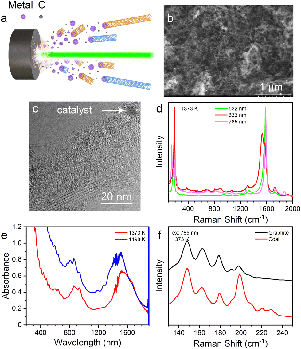 | ||
| Fig. 1 Characterizations of SWCNTs synthesized by LA using coal as the carbon source. (a) Schematic diagram of laser ablation. (b) SEM image, scale bar: 1 μm. (c) TEM image, scale bar: 20 nm. (d) Raman spectra of SWCNTs synthesized at 1373 K with excitation of different wavelengths, green: 532 nm, red: 633 nm, pink: 785 nm. (e) Absorption spectra of SWCNT (synthesized at different temperatures, red: 1373 K, blue: 1198 K) aqueous solutions dispersed by DOC. (f) Raman spectra of SWCNTs synthesized from graphite (black line) and coal (red line) under the same conditions, excitation wavelength: 785 nm. | ||
Herein, we used coal as the carbon source and Co–Ni as the catalyst to prepare targets without binder for the synthesis of SWCNTs by LA. The effects of temperature, pressure and Ar flow rate were studied and the diameter of the SWCNTs was 1.1–1.4 nm. Semiconducting nanotubes of 1.1–1.4 nm present a similar bandgap to silicon, which is preferred in electronic devices.23,41,42 The product was dispersed directly without additional purification which would result in a great loss of SWNCTs.43,44 Sortings based on diameter and conductivity were realized by aqueous two-phase extraction. High-performance field-effect transistors (FETs) were fabricated by the semiconducting SWCNTs separated by PCz (poly[9-(1-octylonoyl)-9H-carbazole-2,7-diyl]) extraction.
Results and discussion
Laser ablation synthesis of SWCNTs from coal
Using coal as the carbon source and Co–Ni as the catalyst, high-quality SWCNTs were synthesized (Fig. 1). The SEM image shows that the as-synthesized product mainly contains the web-like structure formed by nanotubes (Fig. 1(b)). Bundles are the main form of these nanotubes as shown in the TEM image (Fig. 1(c)). The walls of the nanotubes are straight and complete. Besides, there are also catalyst particles and amorphous carbon around the nanotubes, which are common and inevitable in bulk synthesis of SWCNTs. Raman spectra (Fig. 1(d)) with excitation of different wavelengths all show strong RBM (radial breathing mode) and G bands and weak D bands, proving that high-quality SWCNTs were synthesized. The diameter distributions of SWCNTs estimated from the absorption spectra (Fig. 1(e)) of the aqueous solutions of SWCNTs dispersed by DOC (sodium deoxycholate) are ∼1.2–1.4 nm for SWCNTs synthesized at 1373 K (red line in Fig. 1(e)) and ∼1.1–1.3 nm for SWCNTs synthesized at 1198 K (blue line in Fig. 1(e)), which are both smaller and narrower than the diameter of commercial arc-discharged SWCNTs (1.2–1.8 nm45).The graphitization degree of the coal used in our experiment is quite low as the G/D ratio shows in Fig. S1a (ESI†). In addition, no SWCNTs could be found by Raman spectra (Fig. S2, ESI†) when the coal was ablated by a laser without additional catalyst in the target. The compositions of the coal are very complex containing polycyclic aromatic hydrocarbons (Fig. S1b, ESI†) and many elements (Table S1, ESI†). Even so, high-quality SWCNTs could still be synthesized.
We compared the SWCNT samples synthesized from coal and graphite under the same LA conditions. As shown in Fig. 1(f), a strong RBM peak around 199 cm−1 appears in the Raman spectrum of the SWCNTs synthesized from coal at 1373 K, which is much weaker in that from graphite, and the other RBM peaks at lower wavenumbers are almost the same. This shows that the SWCNTs synthesized from coal contain an obviously larger fraction of nanotubes with smaller diameters. The difference is probably caused by the higher content of oxygen and hydrogen in the carbon target of coal (∼4.8% and 0.7% for oxygen and hydrogen, respectively). It's reported that the presence of a suitable amount of oxygen might lead to the selective growth of SWCNTs with smaller diameters.46–48 Likely the slight oxidation of the metallic catalysts can help to keep the small size of the catalytic nanoparticles, which is favourable for growing thin SWCNTs. Meanwhile, the presence of hydrogen indicates the less graphitized structure of the coal target, which results in a higher evaporation rate of carbon and influences the nanotube growth. The results of TGA (thermogravimetry analysis, Fig. S3, ESI†) also show that the yield from coal is higher than that from graphite. At 1123 K, SWCNTs were synthesized using coal as the carbon source, while almost no SWCNTs were detected when using graphite as the carbon source (Fig. S4, ESI†), proving that coal is easier to be ablated than graphite.
The effects of ablation conditions on the diameter distribution were studied as shown in Fig. S5 (ESI†) and Fig. 2. With the increase of the temperature (from bottom to top in Fig. 2(a)), the diameters of the SWCNTs became larger with a red shift in the RBM bands, which is consistent with previous research in graphite processes.24–26 This is largely due to the formation of larger catalyst particles at higher temperature. The decrease of pressure is beneficial to the formation of SWCNTs with smaller diameters but the yield was also decreased (Fig. 2(b)). The influence of Ar flow rate on the diameter of SWCNTs is obvious, but the trend is a kind of complex (Fig. 2(c)). Both pressure and flow rate can affect the temperature gradient and further influence the formation of catalyst nanoparticles and the growth of SWCNTs.
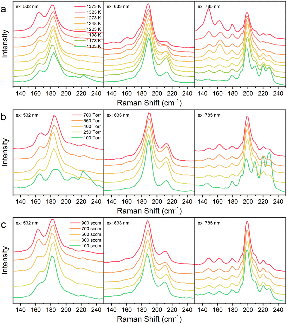 | ||
| Fig. 2 RBM region in the Raman spectra of SWCNTs synthesized under different conditions. (a) The temperature of the tube furnace ranged from 1123 to 1373 K. (b) Pressure ranged from 100 to 700 torr. (c) Ar flow rate ranged from 100 to 900 sccm. Excitation wavelength: 532 nm (left), 633 nm (middle), and 785 nm (right). | ||
Sorting of SWCNTs
SWCNTs grown at 1373 and 1198 K were directly dispersed into aqueous solution by DOC or into toluene solution by PCz without any pre-treatment or pre-purification. Normally before sorting, the as-prepared SWCNTs need to be pre-purified by complicated treatment procedures including annealing, acid treatment, oxidation and so on, to remove catalysts, graphite, amorphous carbon, etc., because large amounts of impurities in raw materials will greatly decrease the efficiency of both dispersion and sorting. But the pre-purification will destroy a considerable amount of SWCNTs43,44 and introduce defects to SWCNTs. There is a trade-off between yield and purity. In this work, without pre-purification, both the concentration and purity of the SWCNT dispersions were high enough, implying that SWCNTs synthesized by LA from coal are of high quality and convenient for sorting and applications.The aqueous solution of SWCNTs was sorted by aqueous two-phase extraction (ATPE). The diameter-based sorting was performed in the DOC–SDS (sodium dodecyl sulphate) system (Fig. 3(a) and (c)) and the conductivity-based sorting was done in the SC (sodium cholate)–SDS system (Fig. 3(b) and (d)) and the photographs of some phases are shown in Fig. 3(e)–(g). During the diameter-based separation process in the DOC–SDS system, with increasing concentration of SDS (from bottom to top in Fig. 3(a) and (c)), the diameters of the SWCNTs in the top phase became smaller as the wavelengths of the absorption peaks showed a blue shift.49 DOC prefers to coat on SWCNTs with small diameters and staying in the bottom phase, while SDS prefers SWCNTs with large diameters and distributing in the top phase.50 As a result, SWCNTs with larger diameters were sorted into the top phase primarily when the concentration of SDS was low. When the concentration of SDS became higher step by step, SWCNTs with smaller diameters were sorted into the top phase. There is no obvious difference of the sorting tendency between the two samples grown at different temperatures. During the separation based on conductivity in the SC–SDS system, before the oxidant NaClO was added into the system, all the SWCNTs distributed in the top phase. When NaClO was added, metallic SWCNTs were oxidized first and sorted into the bottom phase, since metallic SWCNTs are easier to be oxidized than semiconducting SWCNTs. Therefore, semiconducting SWCNTs were enriched in the top phase. Fig. 3(b) and (d) clearly show the removal of metallic tubes (absorption at ∼500–700 nm) in the top phase.
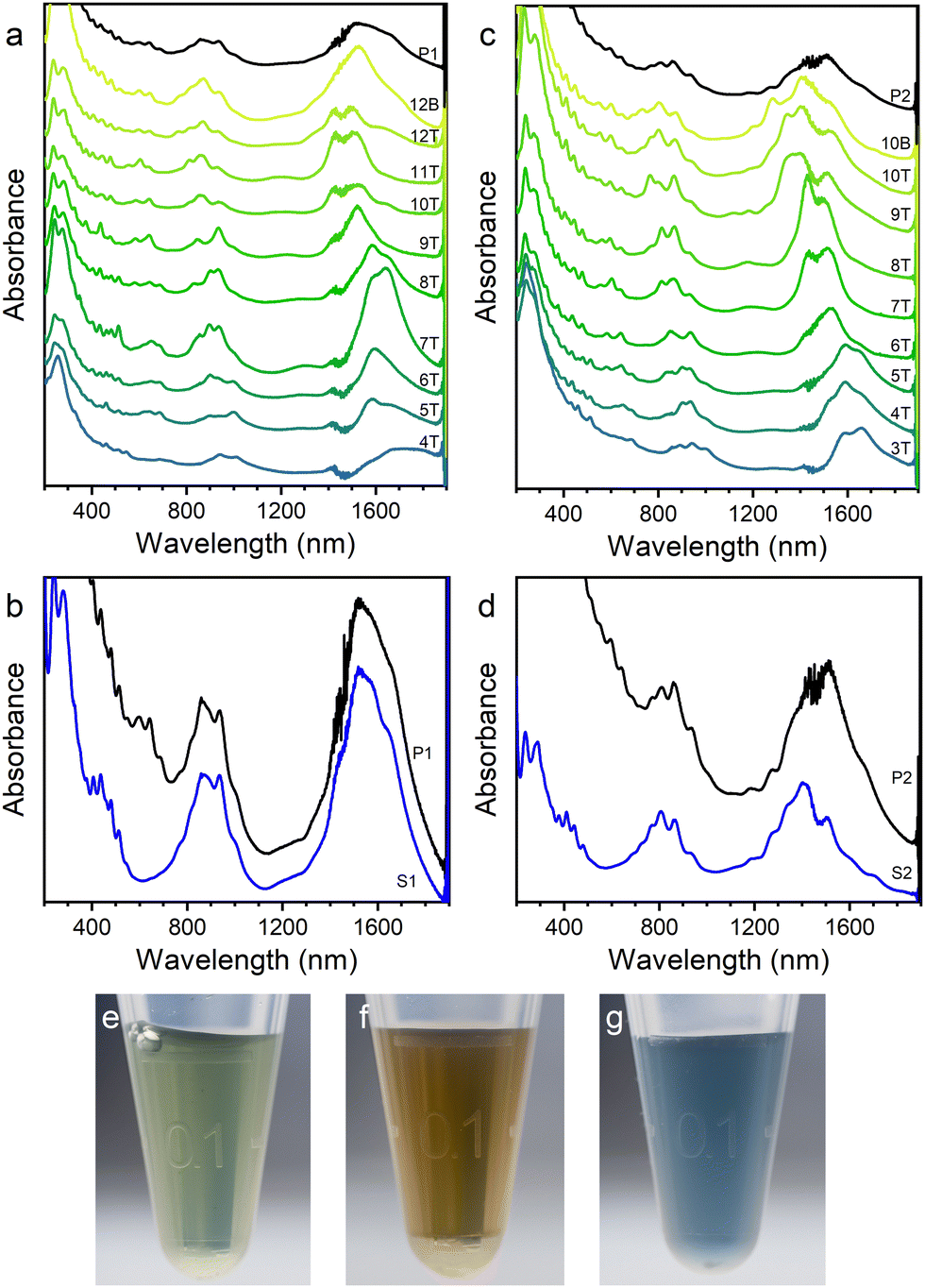 | ||
| Fig. 3 Absorption spectra and photographs of the SWCNTs separated by ATPE. (a) and (b) SWCNTs synthesized at 1373 K. (c) and (d) SWCNTs synthesized at 1198 K. (a) and (c) Separation based on DOC–SDS. (b) and (d) Separation based on SC–SDS and NaClO. P: pristine solution of SWCNTs, T: top phase, B: bottom phase, S: the top phase with semiconducting SWCNTs enriched. (e)–(g) Photographs of some phases from ATPE, (e) 9T in (a), (f) S1 in (b), (g) the bottom phase with metallic SWCNTs enriched corresponding to S1. | ||
SWCNTs synthesized at 1198 K were extracted by PCz in toluene to obtain a dispersion of semiconducting SWCNTs.51 Compared to the as-prepared SWCNTs, the RBM peaks, D-band and G-band in the Raman spectra (Fig. 4(a), (b) and Fig. S6, ESI†) of the SWCNTs sorted by PCz in toluene are all different. It seems that the chirality distribution of SWCNTs (Fig. 4(a) and Fig. S6a, ESI†) is quite different and the G-bands (Fig. 4(b) and Fig. S6b, ESI†) become narrower with a blue shift after being sorted by PCz. There are two main factors that caused these changes. On the one hand, it's well known that the Raman shift and peak width of the RBM52 and G-band53 and the resonance window54 of SWCNTs in different environments are different.55 In the as-synthesized product, SWCNTs are in the form of suspended small bundles and inhomogeneously coated with amorphous carbon, while in the dispersion in toluene, SWCNTs are almost individual and uniformly covered by PCz. This may cause the shift of the RBM and G-bands and the disappearance of some RBM peaks due to the shift of the resonance window. On the other hand, the selective dispersion of SWCNTs by PCz indeed altered the chirality distribution. It's known that PCz presents a selectivity toward semiconducting SWCNTs.51 The disappearance of some of the RBM peaks, for example, the peaks at 189 cm−1 (probably (12,6)) with the excitation of 633 nm (Fig. 4(a)), is due to the removal of metallic tubes. This can be verified by the disappearance of the wide asymmetric Breit–Wigner–Fano (BWF) lineshape of the G-band of metallic SWCNTs (Fig. 4(b) and Fig. S6b, ESI†)56 as well as the absorption spectrum (Fig. 4(c)). After being dispersed by PCz via tip-ultrasonication, defects were introduced on SWCNTs and the lengths of the SWCNTs were also shorted. As a result, the intensity of the D-band became stronger.
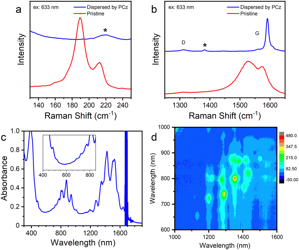 | ||
| Fig. 4 Characterizations of SWCNTs dispersed by PCz in toluene. (a) and (b) Raman spectra of the SWCNT dispersion sorted by PCz in toluene (blue line) and the as-prepared SWCNTs (red line), (a) the region of RBM and (b) the region of the D-band and G-band, excitation wavelength: 633 nm, *: Raman peaks from toluene. (c) Absorption spectrum and (d) photoluminescence spectrum of the SWCNT dispersion. | ||
Estimated from the absorption spectrum (Fig. 4(c)), the purity of semiconducting SWCNTs sorted by PCz for only one time is above 99%57 as there are almost no absorption peaks of metallic SWCNTs. The semiconducting purity would be further improved by repeating the procedures of precipitating out and re-dispersing the SWCNTs.16 Several chiralities were found in the photoluminescence spectrum (Fig. 4(d)), including (11,6), (9,8), (9,7), (10,5), (8,7), (8,6) and so on.
Performance of field-effect transistors (FETs)
The PCz-wrapped SWCNTs dispersed in toluene by a one-step extraction were used to fabricate FETs. The SWCNTs were deposited on the Si substrate and measured by AFM. The density of SWCNTs on the substrate is ∼52 tubes per μm (Fig. 5(a)). To measure the length of the nanotubes, a sparse SWCNT film with much lower density was prepared (Fig. S7, ESI†). Over 80% of the nanotubes present a length between 50 and 300 nm (Fig. 5(b)). FETs with the channel length of 760 nm and width of 30 μm (Fig. S8a and b, ESI†) were fabricated with the dense SWCNT films (Fig. 5(c)). The on/off ratios of the FETs are about 105 to 106 as shown in the transfer characteristics (Vds = −0.1 V, Fig. 5(d) and Fig. S8c, ESI†). Among more than 200 FETs, short circuiting happened only in 4 of them (Fig. S8c, ESI†), presenting a semiconducting nanotube purity consistent with the spectroscopic characterizations. At a small Vds of 0.1 V, channel length of 0.76 μm, and channel width (W) of 30 μm, the transistors show electric current density (Ion/W) of 0.25 ± 0.12 μA μm−1, on/off ratio of 105.79±0.16, threshold voltage of −868 ± 146 mV, transconductance of −13.0 ± 3.4 mS and subthreshold swing of 141 ± 14 mV dec−1 (short-circuited ones excluded). The performances were comparable with the thin-film transistors fabricated from (9,8)-enriched SWCNTs58 or from high-purity semiconducting arc-discharged SWCNTs.51 It should be noted that the performances of the FETs, which served only as a demonstration of the feasibility of our strategy, were not optimal and can be further improved by optimizing the procedures of material purification and device fabrication.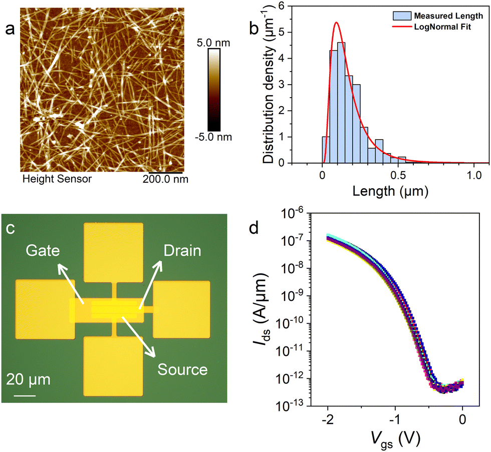 | ||
| Fig. 5 Characterizations of the FETs fabricated by SWCNTs synthesized from coal. (a) AFM image of the SWCNT membrane on the Si substrate, size: 1 μm. (b) Length distribution of the SWCNTs sorted by PCz. (c) Optical photograph of the FET, objective: 50×. (d) Transfer characteristic curves of 10 FETs fabricated by the semiconducting SWCNTs sorted by PCz. | ||
Conclusions
High-quality SWCNTs were synthesized by laser ablation using coal as the carbon source. During the laser ablation process, temperature has an obvious influence on the diameter of the SWCNTs. The nanotubes present a diameter distribution of 1.1–1.4 nm. This diameter range is suitable for applications in electronic devices because semiconducting SWCNTs of this size possess bandgaps comparable to silicon and a well-balanced carrier transport property. Coal has shown to be a better carbon source than graphite in LA preparation of SWCNTs with a higher yield, lower synthesis temperature, and smaller diameter of the resultant nanotubes. Without any pre-purification process, SWCNTs synthesized by LA were dispersed directly to perform conductivity- and diameter-based sorting, which is convenient and avoids loss and damage to the nanotubes. The PCz-extracted semiconducting SWCNTs dispersed in toluene were directly used to fabricate thin film FETs. These FETs show large on/off ratios of 105 to 106.We present an attractive strategy of transforming natural coal into electronic devices with potential in constructing integrated circuits and other systems (Fig. 6). The whole process is feasible and contains less steps than those starting from other carbon sources and by different synthesis techniques. It offers a unique and green way to utilize natural resources producing high value products, inspiring progress in green carbon technology and sustainability.
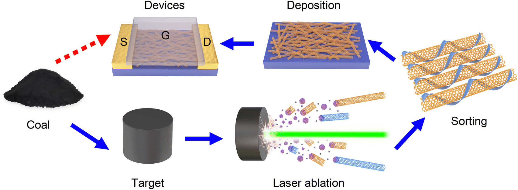 | ||
| Fig. 6 Scheme of the strategy of transforming natural coal into electronic devices. | ||
Experimental methods
Target preparation
Through ball milling, the size of the coal (bitumite, from Shaanxi Province) particles was reduced to a few micro-meters. Then, coal was mixed with Co (99.9%, 1.2 μm, Beijing Zhongkeleiming Daojin Technology Co., Ltd) and Ni (99.9%, 1 μm, 3AChem) at a mass ratio of 100![[thin space (1/6-em)]](https://www.rsc.org/images/entities/char_2009.gif) :5:5. Using a mould with an inner diameter of 9.5 mm, the mixed powder was pressed at 20 MPa for 20 min by a tablet press. Typically, a target with the length of 11 mm would be obtained using 1 g of coal. The target was annealed at 1173 K in Ar for 1 h to remove volatile components. The coal would not be pressed into the columnar target if it was annealed before being moulded or not ball milled. The target of graphite (99.95%, 5000 meshes, Rhawn) was treated in the same way as the coal target without ball milling and annealing.
:5:5. Using a mould with an inner diameter of 9.5 mm, the mixed powder was pressed at 20 MPa for 20 min by a tablet press. Typically, a target with the length of 11 mm would be obtained using 1 g of coal. The target was annealed at 1173 K in Ar for 1 h to remove volatile components. The coal would not be pressed into the columnar target if it was annealed before being moulded or not ball milled. The target of graphite (99.95%, 5000 meshes, Rhawn) was treated in the same way as the coal target without ball milling and annealing.
Laser ablation
During the ablation process, the target was fixed in a quartz holder with the inner diameter of 10 mm and placed in a quartz tube with a diameter of 1 inch. A pulse laser (Nd:YAG, 532 nm, 10 Hz, 300 mJ per pulse, Changchun New Industries Optoelectronics Technology Co., Ltd) was focused to a spot with a diameter of about 2 mm on the target surface. Typically, the synthesis was performed at 1198 K, 400 torr, with 300 sccm Ar, for 10–20 min. Laser-light protective goggles were worn to prevent laser damage to the eyes.Aqueous two-phase extraction
2% (wt) DOC (Sigma-Aldrich) was used to disperse SWCNTs into the aqueous solution by tip-sonication (7 W, 90 min, with ice-water bath). The supernatant was collected as the SWCNT dispersion after centrifugation at 17 kG for 90 min.The aqueous two-phase extraction was performed in a polyethylene glycol (PEG, 6 kDa, Alfa Aesar)/dextran (DX, 70 kDa, TCI) system. Typically, the top phase was always extracted and new blank top phase together with surfactant, including DOC, SC (Sigma-Aldrich) and SDS (Sigma-Aldrich), or oxidant, such as NaClO (Sigma-Aldrich), would be added into the bottom phase. After thorough mixing and centrifugation at 10 kG for 2 min, phase separation occurred. Then, the above procedures were repeated. The detailed process is given in Tables S2–S5 (ESI†).
Sorting by PCz
In toluene, 2 mg mL−1 PCz (Shanghai yuanye Bio-Technology Co., Ltd) was used as the dispersant of SWCNTs. The tip-sonication was performed at 4 W for 90 min in an ice-water bath. The dispersion in toluene was obtained after centrifugation at 17 kG for 15 min.Before deposition onto the substrate, the excess PCz in the SWCNT dispersion was removed. The dispersion was filtered through a 0.1 μm PTFE filter membrane and the sediment was washed by toluene. Then, the sediment was re-dispersed in toluene by tip-sonication at 1 W for 30 min in an ice-water bath. After centrifugation at 21 kG for 20 min, the dispersion was suitable for deposition on the substrate.
Fabrication of FETs
After being treated with air-plasma for 10 min, a silicon substrate (2.5 × 2.5 cm) was covered with the previously mentioned dispersion of semiconducting SWCNTs in toluene for 30 min to allow the SWCNTs to be deposited. Then, the FET region was defined by etching SWCNTs with O2-plasma, and a conductive channel with a length of 760 nm was made by photolithography. 40 nm Pd was deposited by electron beam evaporation as the source and drain contacts of SWCNT-FETs. 3 nm Y2O3 (deposited by electron beam evaporation) and 8 nm HfO2 (deposited by atomic layer deposition) were used as the gate dielectric layer. Finally, 40 nm Au deposited by electron beam evaporation was used as the gate electrode.Author contributions
Conceptualization: Y. L., S. C.; investigation: S. C., Y. C., X. Z., Z. H., H. L., Y. Y., C. X., J. S., Y. X., L. G., N. G.; methodology: Y. L., H. X., M. L.; supervision: Y. L., Z. Z., L. P.; writing – original draft: S. C.; writing – review & editing: Y. L.Conflicts of interest
There are no conflicts to declare.Acknowledgements
We thank Prof. Yohji Achiba and Prof. Shigeo Maruyama for the helpful discussion. This work was supported by the National Natural Science Foundation of China (22120102004, U21A6004, 22201014), Ministry of Science and Technology of the People's Republic of China (2022YFA1203301), Shenzhen KQTD Project (KQTD20180411143400981), Science and Technology Major Project of Shanxi (No. 202101030201022), and Beijing National Laboratory for Molecular Sciences (BNLMS-CXTD-202001).Notes and references
- M. He, Y. Sun and B. Han, Angew. Chem., Int. Ed., 2022, 61, e202112835 CrossRef CAS PubMed.
- P. Gao, L. Zhong, B. Han, M. He and Y. Sun, Angew. Chem., Int. Ed., 2022, 61, e202210095 CrossRef CAS PubMed.
- S. Miao, H. Zhao, M. Kang, H. Shen, W. Song, D. Zhao, J. Ye and Z. Li, Chem. Commun., 2019, 55, 7954–7957 RSC.
- X. Zhao, W. Jia, X. Wu, Y. Lv, J. Qiu, J. Guo, X. Wang, D. Jia, J. Yan and D. Wu, Carbon, 2020, 156, 445–452 CrossRef CAS.
- M. Li, W.-Y. Tsai, B. P. Thapaliya, H. M. Meyer, B. L. Armstrong, H. Luo, S. Dai, J. Nanda and I. Belharouak, Carbon, 2021, 172, 414–421 CrossRef CAS.
- K. Wang, F. Sun, H. Wang, D. Wu, Y. Chao, J. Gao and G. Zhao, Adv. Funct. Mater., 2022, 32, 2203725 CrossRef CAS.
- P. Yao, J. Cen, M. Fang, T. Wang and Q. Wang, RSC Adv., 2018, 8, 17558–17568 RSC.
- H. Zhao, L. Wang, D. Jia, W. Xia, J. Li and Z. Guo, J. Mater. Chem. A, 2014, 2, 9338–9344 RSC.
- Q. Zhou, Z. Zhao, Y. Zhang, B. Meng, A. Zhou and J. Qiu, Energy Fuels, 2012, 26, 5186–5192 CrossRef CAS.
- J. Tamuly, D. Bhattacharjya and B. K. Saikia, Energy Fuels, 2022, 36, 12847–12874 CrossRef CAS.
- K. A. Williams, M. Tachibana, J. L. Allen, L. Grigorian, S. C. Cheng, S. L. Fang, G. U. Sumanasekera, A. L. Loper, J. H. Williams and P. C. Eklund, Chem. Phys. Lett., 1999, 310, 31–37 CrossRef CAS.
- J. Qiu, Y. Li, Y. Wang, T. Wang, Z. Zhao, Y. Zhou, F. Li and H. Cheng, Carbon, 2003, 41, 2170–2173 CrossRef CAS.
- L. Wu, J. Liu, B. R. Reddy and J. Zhou, Fuel Process. Technol., 2022, 229, 107171 CrossRef CAS.
- C. Qiu, Z. Zhang, M. Xiao, Y. Yang, D. Zhong and L. M. Peng, Science, 2017, 355, 271–276 CrossRef CAS PubMed.
- C. Qiu, F. Liu, L. Xu, B. Deng, M. Xiao, J. Si, L. Lin, Z. Zhang, J. Wang, H. Guo, H. Peng and L. M. Peng, Science, 2018, 361, 387–392 CrossRef CAS PubMed.
- L. Liu, J. Han, L. Xu, J. Zhou, C. Zhao, S. Ding, H. Shi, M. Xiao, L. Ding, Z. Ma, C. Jin, Z. Zhang and L. M. Peng, Science, 2020, 368, 850–856 CrossRef CAS PubMed.
- G. Hills, C. Lau, A. Wright, S. Fuller, M. D. Bishop, T. Srimani, P. Kanhaiya, R. Ho, A. Amer, Y. Stein, D. Murphy, Arvind, A. Chandrakasan and M. M. Shulaker, Nature, 2019, 572, 595–602 CrossRef CAS PubMed.
- A. Saha, B. J. Gifford, X. He, G. Ao, M. Zheng, H. Kataura, H. Htoon, S. Kilina, S. Tretiak and S. K. Doorn, Nat. Chem., 2018, 10, 1089–1095 CrossRef CAS PubMed.
- Y. Yomogida, T. Tanaka, M. Zhang, M. Yudasaka, X. Wei and H. Kataura, Nat. Commun., 2016, 7, 12056 CrossRef CAS PubMed.
- P. V. Jena, D. Roxbury, T. V. Galassi, L. Akkari, C. P. Horoszko, D. B. Iaea, J. Budhathoki-Uprety, N. Pipalia, A. S. Haka, J. D. Harvey, J. Mittal, F. R. Maxfield, J. A. Joyce and D. A. Heller, ACS Nano, 2017, 11, 10689–10703 CrossRef CAS PubMed.
- T. Guo, P. Nikolaev, A. G. Rinzler, D. Tomanek, D. T. Colbert and R. E. Smalley, J. Phys. Chem., 1995, 99, 10694–10697 CrossRef CAS.
- T. Guo, P. Nikolaev, A. Thess, D. T. Colbert and R. E. Smalley, Chem. Phys. Lett., 1995, 243, 49–54 CrossRef CAS.
- Y. Chen, M. Lyu, Z. Zhang, F. Yang and Y. Li, ACS Cent. Sci., 2022, 8, 1490–1505 CrossRef CAS PubMed.
- S. Bandow, S. Asaka, Y. Saito, A. M. Rao, L. Grigorian, E. Richter and P. C. Eklund, Phys. Rev. Lett., 1998, 80, 3779–3782 CrossRef CAS.
- H. Kataura, Y. Kumazawa, Y. Maniwa, Y. Ohtsuka, R. Sen, S. Suzuki and Y. Achiba, Carbon, 2000, 38, 1691–1697 CrossRef CAS.
- R. Sen, Y. Ohtsuka, T. Ishigaki, D. Kasuya, S. Suzuki, H. Kataura and Y. Achiba, Chem. Phys. Lett., 2000, 332, 467–473 CrossRef CAS.
- M. Yudasaka, T. Komatsu, T. Ichihashi, Y. Achiba and S. Iijima, J. Phys. Chem. B, 1998, 102, 4892–4896 CrossRef CAS.
- E. Munoz, W. K. Maser, A. M. Benito, M. T. Martinez, G. F. de la Fuente, Y. Maniette, A. Righi, E. Anglaret and J. L. Sauvajol, Carbon, 2000, 38, 1445–1451 CrossRef CAS.
- O. Jost, A. A. Gorbunov, J. Möller, W. Pompe, X. Liu, P. Georgi, L. Dunsch, M. S. Golden and J. Fink, J. Phys. Chem. B, 2002, 106, 2875–2883 CrossRef CAS.
- S. Lebedkin, P. Schweiss, B. Renker, S. Malik, F. Hennrich, M. Neumaier, C. Stoermer and M. M. Kappes, Carbon, 2002, 40, 417–423 CrossRef CAS.
- S. S. Harilal, C. V. Bindhu, V. P. N. Nampoori and C. P. G. Vallabhan, Appl. Phys. Lett., 1998, 72, 167–169 CrossRef CAS.
- E. Munoz, W. K. Maser, A. M. Benito, G. F. de la Fuente and M. T. Martinez, Synth. Met., 1999, 103, 2490–2491 CrossRef CAS.
- B. J. Landi and R. P. Raffaelle, J. Nanosci. Nanotechnol., 2007, 7, 883–890 CrossRef CAS PubMed.
- H. Kataura, A. Kimura, Y. Ohtsuka, S. Suzuki, Y. Maniwa, T. Hanyu and Y. Achiba, Jpn. J. Appl. Phys., 1998, 37, L616–L618 CrossRef CAS.
- M. Yudasaka, R. Yamada, N. Sensui, T. Wilkins, T. Ichihashi and S. Iijima, J. Phys. Chem. B, 1999, 103, 6224–6229 CrossRef CAS.
- M. Zhang, M. Yudasaka and S. Iijima, J. Phys. Chem. B, 2004, 108, 12757–12762 CrossRef CAS.
- M. Yudasaka, F. Kokai, K. Takahashi, R. Yamada, N. Sensui, T. Ichihashi and S. Iijima, J. Phys. Chem. B, 1999, 103, 3576–3581 CrossRef CAS.
- N. Braidy, M. A. El Khakani and G. A. Botton, Chem. Phys. Lett., 2002, 354, 88–92 CrossRef CAS.
- M. Yudasaka, T. Ichihashi and S. Iijima, J. Phys. Chem. B, 1998, 102, 10201–10207 CrossRef CAS.
- M. Yudasaka, T. Ichihashi, T. Komatsu and S. Iijima, Chem. Phys. Lett., 1999, 299, 91–96 CrossRef CAS.
- X. Yang, T. Liu, R. Li, X. Yang, M. Lyu, L. Fang, L. Zhang, K. Wang, A. Zhu, L. Zhang, C. Qiu, Y. Z. Zhang, X. Wang, L. M. Peng, F. Yang and Y. Li, J. Am. Chem. Soc., 2021, 143, 10120–10130 CrossRef CAS PubMed.
- Z. Zhang, Y. Yao and Y. Li, Acta Phys.-Chim. Sin., 2021, 37, 2101055 Search PubMed.
- H. G. Cho, S. W. Kim, H. J. Lim, C. H. Yun, H. S. Lee and C. R. Park, Carbon, 2009, 47, 3544–3549 CrossRef CAS.
- A. B. Makama, A. Salmiaton, N. Abdullah, T. S. Y. Choong and E. B. Saion, Sep. Sci. Technol., 2014, 49, 2797–2812 CrossRef CAS.
- F. Liu, X. Chen, M. Xi, N. Wei, L. Bai, L. Peng, Y. Cao and X. Liang, Nano Res., 2022, 15, 8479–8485 CrossRef CAS.
- B. Xu, T. Kaneko, Y. Shibuta and T. Kato, Sci. Rep., 2017, 7, 11149 CrossRef PubMed.
- M. H. Li, X. Y. Liu, X. L. Zhao, F. Yang, X. Wang and Y. Li, Top. Curr. Chem., 2017, 375, 29 CrossRef PubMed.
- H. Takezaki, T. Inoue, R. Xiang, S. Chiashi and S. Maruyama, Diamond Relat. Mater., 2019, 96, 160–166 CrossRef CAS.
- J. A. Fagan, C. Y. Khripin, C. A. Silvera Batista, J. R. Simpson, E. H. Haroz, A. R. Hight Walker and M. Zheng, Adv. Mater., 2014, 26, 2800–2804 CrossRef CAS PubMed.
- H. Li, G. Gordeev, O. Garrity, S. Reich and B. S. Flavel, ACS Nano, 2019, 13, 2567–2578 CAS.
- J. Gu, J. Han, D. Liu, X. Yu, L. Kang, S. Qiu, H. Jin, H. Li, Q. Li and J. Zhang, Small, 2016, 12, 4993–4999 CrossRef CAS PubMed.
- J. Yang, D. Zhang, Y. Hu, C. Xia, S. Sun and Y. Li, ACS Nano, 2017, 11, 10509–10518 CrossRef CAS PubMed.
- M. Steiner, M. Freitag, J. C. Tsang, V. Perebeinos, A. A. Bol, A. V. Failla and P. Avouris, Appl. Phys. A: Mater. Sci. Process., 2009, 96, 271–282 CrossRef CAS.
- J. S. Park, Y. Oyama, R. Saito, W. Izumida, J. Jiang, K. Sato, C. Fantini, A. Jorio, G. Dresselhaus and M. S. Dresselhaus, Phys. Rev. B: Condens. Matter Mater. Phys., 2006, 74, 165414 CrossRef.
- D. Zhang, J. Yang and Y. Li, Small, 2013, 9, 1284–1304 CrossRef CAS PubMed.
- S. D. M. Brown, A. Jorio, P. Corio, M. S. Dresselhaus, G. Dresselhaus, R. Saito and K. Kneipp, Phys. Rev. B: Condens. Matter Mater. Phys., 2001, 63, 155414 CrossRef.
- L. Wei, B. S. Flavel, W. Li, R. Krupke and Y. Chen, Nanoscale, 2017, 9, 11640–11646 RSC.
- L. Wei, B. Liu, X. Wang, H. Gui, Y. Yuan, S. Zhai, A. K. Ng, C. Zhou and Y. Chen, Adv. Electron. Mater., 2015, 1, 1500151 CrossRef.
Footnote |
| † Electronic supplementary information (ESI) available: Characterizations of coal used in this work, detailed characterizations of SWCNTs, dispersion of SWCNTs and FETs, and detailed separation process of aqueous two-phase extraction. See DOI: https://doi.org/10.1039/d3mh01053h |
| This journal is © The Royal Society of Chemistry 2023 |