
Ionic liquid-based electrolysis-deposition for modulating Pb crystal facets to boost CO2 electroreduction†
Chongyang
Jiang
ab,
Shaojuan
Zeng
*a,
Jiaqi
Feng
c,
Guilin
Li
a,
Zongxu
Wang
a,
Kuilin
Peng
a,
Lu
Bai
 a and
Xiangping
Zhang
*ab
a and
Xiangping
Zhang
*ab
aBeijing Key Laboratory of Ionic Liquids Clean Process, State Key Laboratory of Multiphase Complex Systems, Institute of Process Engineering, Chinese Academy of Sciences, Beijing 100190, China. E-mail: xpzhang@ipe.ac.cn; sjzeng@ipe.ac.cn; Fax: +8610 6255 8174
bSchool of Future Technology, University of Chinese Academy of Sciences, Beijing 100049, China
cKey Laboratory of Colloid and Interface and Thermodynamics, Institute of Chemistry, Chinese Academy of Sciences, Beijing 100190, China
First published on 11th March 2023
Abstract
The crystal facet of electrodes is one of the main factors affecting the activity of CO2 electroreduction. Herein, a new ionic liquid (IL)-based electrolysis-deposition (ED) method was developed for modulating the Pb crystal facet to boost CO2 electroreduction. ED-Pb with an electrodeposition time of 900 s showed a high formate partial current density of 110.8 mA cm−2 with over 80% formate faradaic efficiency at −2.4 V (vs. Ag/Ag+), which is much higher than values using a Pb planar electrode with 19.8 mA cm−2 partial current density and 70% faradaic efficiency. Experimental results and density functional theory calculations revealed that ED-Pb catalysts have the dominant Pb(111) crystal facet due to the different adsorption energies of the IL on the crystal facet, and the improved performance is attributed to the low Gibbs free energy of OCHO* intermediates on the Pb(111) crystal facet. This work provides a new strategy for regulating the structures of electrocatalysts for high-activity CO2 electroreduction.
Introduction
Electrochemical CO2 reduction reaction (CO2RR) to value-added products using renewable energy has been considered as an economically attractive approach for reducing the amount of CO2 in the atmosphere.1–4 Among the possible CO2 electroreduction products, formate as an important chemical intermediate and hydrogen carrier, is one of the most economical and viable products of the CO2RR.5–9 Over the past decades, vigorous efforts have been made to develop electroreduction systems for high-efficiency CO2RR to formate. To date, some active metal electrocatalysts, such as Bi, Sn, In, and Pb, have been used for CO2 electroreduction to formate with significant progress.10–12 Among these metal electrocatalysts, Pb-based electrocatalysts are stable, hardly react with water and air, and are cheaper than those of other metals. At the same time, Pb-based catalysts have been widely studied for CO2 electroreduction due to their high selectivity for formate products and intrinsic inertness of the hydrogen evolution reaction (HER).13–15 However, most of the reported Pb-based catalysts still suffer from a low formation rate that leads to unsatisfactory CO2 electroreduction performance.16–18In recent works, some means have been proposed to stabilize the reaction intermediates and improve the activity of CO2 electroreduction to formate by Pb-based catalysts.19–22 In terms of catalyst design, the selectivity of Pb-based catalysts is dependent on surface morphology, crystal surface structure, and structural composition.23–25 Electrodeposition can lead to special morphology with large electrochemically active surface areas that are hypothesized to be catalytically active sites.26 Guay et al.27 designed honeycomb porous Pb films, which can significantly increase the formate current density (jformate, 7.5 mA cm−2) and faradaic efficiency (FEformate, 97%). The enhanced performance of the porous Pb films was attributed to the dendritic secondary structure that could help to stabilize the intermediates in the boundary layer. In addition, ionic liquids (ILs), as new solvents, can be directly used as reaction solvents to regulate the crystal facets of catalysts.28,29 For example, Zhang et al.29 used 1-hexyl-3-methylimidazolium tetrafluoroborate ([Hmim][BF4]) as the solvent to prepare the flowerlike In2S3 catalyst with a dominant (440) crystal facet, exhibiting a formate formation rate of 478 μmol cm−2 h−1 with 86% FEformate. Moreover, ILs not only modified the catalyst crystal facet but also improved the current density and product selectivity as CO2RR electrolytes.30–33 Although the CO2 electroreduction to formate system has been extensively studied, it is still extremely challenging to achieve satisfactory formate formation rates using Pb-based materials.
Herein, a novel IL-based electrolysis-deposition method for modulating Pb crystal facets (ED-Pb) was proposed, which can significantly enhance the activity of CO2 electroreduction to formate. This electrolysis-deposition process was observed by an operando optical microscope (OM), and ED-Pb catalysts with different crystal facet ratios were obtained by altering the electrodeposition conditions. Furthermore, combined with experimental characterization techniques and density functional theory (DFT) calculations, the mechanism of high CO2 electrochemical performance to formate by ED-Pb electrodes was systematically investigated, which will provide a new and efficient method for modifying the catalyst crystal facet to boost CO2RR activity.
Experimental section
Fabrication of ED-Pb electrodes
ED-Pb electrodes were prepared by the IL-based electrolysis-deposition method at room temperature. The cell is an ordinary H-type electrolytic cell separated by Nafion 117 membrane. Before electrolysis-deposition experiments, Pb planar electrodes (≥99.9%, area: 1 × 1 cm2, thickness: 0.5 mm) were polished with #600 and #2000 sandpaper until the surface was smooth and then washed with water and acetone in sequence. The pre-treated Pb planar electrodes, Ag/Ag+, and platinum gauze were used as the working electrode, reference electrode, and counter electrode, respectively. Unless stated otherwise, all the potentials in this study were versus the Ag/Ag+ reference electrode. The working and reference electrodes were placed in the cathode chamber with 0.5 M 1-butyl-3-methylimidazolium trifluoroacetate ([Bmim][TFA], Fig. S1†)/acetonitrile (AcN) solution, while the counter electrode was placed in the anode chamber with a 0.1 M H2SO4 solution as the electrolyte.A two-step electrolysis-deposition process with switching cathode/anode of the H-type cell was used to prepare highly active ED-Pb electrodes. First, the electrolysis process was carried out at −0.1 A for 900 s to form Pb ions by polarizing the Pb planar electrode. Second, the deposition process was carried out at a constant current (such as 0.1 A for 900 s) and the Pb ions were reduced to form the active ED-Pb electrode. The deposition morphology and crystal facet of ED-Pb electrodes could be tuned by applying different deposition times and currents (450 s-0.2 A; 900 s-0.1 A: 1800 s-0.05 A; and 3600 s-0.025 A; total charge of 90 C) during the deposition process, and the corresponding electrodes were annotated as ED-Pb-450, ED-Pb-900, ED-Pb-1800, and ED-Pb-3600, respectively. After the electrolysis-deposition process, the obtained black-colored ED-Pb electrodes were further washed with AcN and dried under an N2 atmosphere.
Physical characterization
An operando optical microscope (OM) study was carried out using a SangNond light microscope (SN0745-SN108060SDU). The morphologies of the ED-Pb electrodes were detected by scanning electron microscopy (SEM, Hitachi SU8020) and transmission electron microscopy (TEM, JEOL JEM−2100 system). The crystal structures of the ED-Pb electrodes were investigated by X-ray diffraction (XRD, Rigaku Smartlab diffractometer) using a Cu Kα (λ = 1.5418 Å) radiation source with a scanning rate of 15° min−1.Evaluation of CO2 electroreduction performance
All the CO2 electrochemical experiments were performed in a H-type cell using an electrochemical workstation (CHI660E, Shanghai Chenhua Instrument Co, Ltd). The ED-Pb electrodes were used as the working electrode, and Ag/Ag+ and platinum wire were used as the reference and counter electrodes, respectively. The working and reference electrodes were placed in the cathode chamber with 1-butyl-3-methylimidazolium hexafluorophosphate ([Bmim][PF6])/AcN–H2O solution mixture, while the counter electrode was placed in the anode chamber with a 0.1 M H2SO4 solution as the electrolyte. The electrochemical performances were characterized by linear sweep voltammetry (LSV), cyclic voltammetry (CV), and electrochemical impedance spectroscopy (EIS). LSV was carried out in a potential range of −1.5 to −2.4 V at a scan rate of 20 mV s−1 in N2 or CO2-saturated IL electrolyte. The electrochemically active surface area (ECSA) was determined by the double-layer capacitances calculated from a plot of discharging current density vs. scan rate, while the electric double-layer capacitance was determined by CV measurement at various scan rates (10 to 100 mV s−1) from potentials of −0.7 to −0.8 V. EIS was performed within a frequency range of 0.01 to 0.1 MHz. CO2 electroreduction was carried out at various constant potentials (−2.0 to −2.4 V) for 1 h. During the reduction process, CO2 was continuously bubbled into the reactor with a gas flow rate of 30 mL min−1.Results and discussion
A schematic diagram of the ED-Pb electrode preparation process is shown in Fig. S2.† Compared with the catalyst preparation methods reported in previous literature (solvent-thermal reaction, chemical vapor deposition and chemical etching),29,34,35 the preparation of ED-Pb catalysts in IL electrolytes by electrolysis-deposition requires mild conditions, short time, and a simple preparation process. The obtained catalyst can be directly used for catalytic reactions, avoiding the addition of binders.36,37 Conventional electrodeposition was carried out in a mixed solution containing metal salts with other solutes.27,38,39 We obtained Pb2+ metal ions by electrolysis, and then electrodeposition was performed to produce ED-Pb electrodes to achieve efficient utilization of metal ions in this work. At the same time, the electrolyte undergoes no change and can be recycled after the whole electrolysis-deposition process.To monitor the dynamic Pb electrolysis-deposition reaction in the [Bmim][TFA] electrolyte, an in situ OM investigation was conducted. A set of typical visualization results are shown in Fig. 1a and b (see ESI II† for the video of the electrolysis-deposition process). The Pb planar electrode was quite uniform before electrolysis. The surface of the Pb planar electrode drops gradually relative to its starting position at a current of −0.1 A, indicating that the Pb planar electrode is polarized to form Pb ions. Subsequently, at a current of 0.1 A, a black material was deposited and grew quickly to cover the Pb planar electrode surface, which could be due to the reduction of Pb ions in the solution to Pb. The same electrolysis-deposition process was carried out in an aqueous solution and IL electrolytes, and the potential curve over time is shown in Fig. S3.† In aqueous solutions, the oxidation potential was approximately 2 V (Fig. S3b†) and the experimental results showed that a large number of bubbles are generated on the Pb electrode surface, which is more prone to the oxygen evolution reaction. The IL electrolytes included 1-butylpyridinium chloride ([BPy][Cl]), tetrabutylphosphine chloride ([P4444][Cl]), 1-butyl-3-methylimidazolium chloride ([Bmim][Cl]), 1-butyl-3-methylimidazolium acetate ([Bmim][Ac]), and 1-butyl-3-methylimidazolium bistrifluoromethanesulfonate ([Bmim][NTf2]) (Fig. S4†). As can be seen from Fig. S3,† the potential curves of the three ILs ([BPy][Cl], [P4444][Cl], and [Bmim][Cl]) containing the Cl− anions with different cations were similar to [Bmim][TFA], and the black material was found on the Pb planar electrode in all three IL electrolytes. It can be seen that the cations of ILs have little effect on the electrolysis-deposition process. At a current density of 0.1 A in the [Bmim][Ac] electrolyte, the applied potential exceeds the range of the electrochemical station (CHI 660E, potential range of ±10 V) and the electrolysis process is terminated (Fig. S3f†). When the IL contains halogens ([Bmim][NTf2] and [Bmim][Cl]), a similar curve appears, and a black material appears on the Pb planar electrode surface, mainly because the halogen ion radius is small and the reactivity is high. Then the substrate can be quickly corroded in the early stage of polarization, intensifying the dissolution of Pb in the form of ions.40,41 These results indicated that the electrolysis-deposition process depends on the composition of the electrolyte, and the IL electrolyte containing halogens can promote the oxidation of Pb to Pb ions.
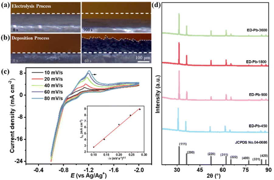 | ||
| Fig. 1 In situ OM images of the Pb planar electrode in 0.5 M [Bmim][TFA]/AcN electrolyte (a) at −0.1 A for 900 s in the electrolysis process and (b) at 0.1 A for 900 s in the electrodeposition process. (c) Cyclic voltammograms of the Pb planar electrode at −0.6 to −2.0 V after the Pb electrolysis process (the inset illustration: relationship between √v and jpc). (d) XRD patterns of the Pb standard PDF card (No. 04-0686) and ED-Pb electrodes with different deposition times. | ||
To study the valence state of the Pb ions in the IL electrolyte, cyclic voltammograms (CV) after the Pb electrolysis process at different sweep rates, including 10, 20, 40, 60 and 80 mV s−1, were obtained as shown in Fig. 1c. The reduction potential of Pb was about −1.2 V, which is close to the standard electrode potential of Pb2+ (−0.1251 V vs. RHE).42 Subsequently, an equal molar amount of Pb(CH3COO)2 was added to the 0.5 M [Bmim][AC]/AcN electrolyte to observe the deposition CV curve with a reduction potential of −1.23 V (Fig. S3h†). From the electrolysis-deposition process, it could be inferred that Pb is firstly oxidized to Pb2+, and then Pb2+ is reduced to form metallic Pb. The Pb electrodeposition reaction is controlled by multiple facets, including kinetics, crystallographic thermodynamics, and ion diffusion. Thus, based on the CV results, it can be seen that as the scan rate increased from 10 to 80 mV s−1, the reduction potential peak moved from −1.11 to −1.21 V and the reduction current density peak (jpc) gradually increased from 3.49 to 8.94 mA cm−2. Therefore, the Pb electrodeposition process is irreversible. The linear relationship between the square root of the scan rate (√v) and jpc is shown in the inset of Fig. 1c, which indicates that the Pb electrodeposition process is controlled by diffusion. These results show that the electrodeposition process is complex and the parameters of the electrolysis-deposition process directly affect the structure of ED-Pb.43,44
To understand the structures of electrodes, the powder X−ray diffraction (XRD) technique was utilized to reveal the crystal facet composition of the Pb electrode. As shown in Fig. S5,† the peak positions of the Pb planar electrode before and after electrolysis are 31.3°, 36.3°, 52.2°, 62.1°, 65.2°, 76.9°, 85.4° and 88.2°, corresponding to the Pb crystal facets of (111), (200), (220), (311), (222), (400), (331) and (420) (JCPDS card No. 04-0686), respectively. The relative peak intensity ratio of the Pb planar electrode at Pb(111)![[thin space (1/6-em)]](https://www.rsc.org/images/entities/char_2009.gif) :Pb(200) (I111:I200) was also calculated. The I111:I200 of the Pb planar electrode before electrolysis was 2.0, while the I111:I200 of the Pb planar electrode after electrolysis was 1.67, indicating that metallic Pb is polarized to form Pb2+ ions during the electrolysis process. The diffraction peaks of all the ED-Pb electrodes were the same as those of Pb (JCPDS card No. 04-0686) (Fig. 1d), and the I111:I200 of the ED-Pb electrodes were calculated as 2.17, 3.20, 2.40, and 2.38 from ED-Pb-450 to ED-Pb-3600. The clear lattice fringes were observed on the TEM images of the ED-Pb-900 electrode, and the fringe spacing of 0.285 nm was consistent with the interplanar spacing of the Pb(111) crystal facet (Fig. S6†). Therefore, ED-Pb-900 electrodes have a dominant crystal facet of Pb(111) compared to that of Pb(200). The experimental results indicated that ED-Pb electrodes with different relative peak intensity ratios can be adjusted by varying the applied deposition parameters. In order to understand the ED-Pb electrode with the dominant Pb(111) crystal facet, we studied the surface energy of the Pb crystal facet using computational analysis. The surface energies of the Pb(111) and Pb(200) crystal facets were 0.0278 and 0.0343 eV A−2, respectively (Fig. S7a†). It was reported that the lower surface energy of the crystal facet would result in a slower growth rate.43 In addition, the adsorption energy of [Bmim][TFA] on the Pb(111) and Pb(200) crystal facets was calculated. The adsorption energy on Pb(111) is −1.16 eV, which is lower than the adsorption energy on Pb(200) (−1.02 eV) (Fig. S7b†), and the low adsorption energy will inhibit the growth of the crystal facet. Therefore, ED-Pb electrodes have a dominant crystal facet of Pb(111) compared to Pb(200).
:Pb(200) (I111:I200) was also calculated. The I111:I200 of the Pb planar electrode before electrolysis was 2.0, while the I111:I200 of the Pb planar electrode after electrolysis was 1.67, indicating that metallic Pb is polarized to form Pb2+ ions during the electrolysis process. The diffraction peaks of all the ED-Pb electrodes were the same as those of Pb (JCPDS card No. 04-0686) (Fig. 1d), and the I111:I200 of the ED-Pb electrodes were calculated as 2.17, 3.20, 2.40, and 2.38 from ED-Pb-450 to ED-Pb-3600. The clear lattice fringes were observed on the TEM images of the ED-Pb-900 electrode, and the fringe spacing of 0.285 nm was consistent with the interplanar spacing of the Pb(111) crystal facet (Fig. S6†). Therefore, ED-Pb-900 electrodes have a dominant crystal facet of Pb(111) compared to that of Pb(200). The experimental results indicated that ED-Pb electrodes with different relative peak intensity ratios can be adjusted by varying the applied deposition parameters. In order to understand the ED-Pb electrode with the dominant Pb(111) crystal facet, we studied the surface energy of the Pb crystal facet using computational analysis. The surface energies of the Pb(111) and Pb(200) crystal facets were 0.0278 and 0.0343 eV A−2, respectively (Fig. S7a†). It was reported that the lower surface energy of the crystal facet would result in a slower growth rate.43 In addition, the adsorption energy of [Bmim][TFA] on the Pb(111) and Pb(200) crystal facets was calculated. The adsorption energy on Pb(111) is −1.16 eV, which is lower than the adsorption energy on Pb(200) (−1.02 eV) (Fig. S7b†), and the low adsorption energy will inhibit the growth of the crystal facet. Therefore, ED-Pb electrodes have a dominant crystal facet of Pb(111) compared to Pb(200).
The electrolysis-deposition of the Pb planar electrodes not only avoids using binders (e.g. Nafion), which always causes a complex electrode preparation process and unstable electrode interface, but also facilitates the formation of various microstructures by tuning the deposition parameters.45 The electrode morphology has a critical effect on the CO2RR.23,26,46 Therefore, SEM was used to characterize the morphology of all the Pb electrodes. Compared with the smooth Pb surface before electrolysis, the surface of the Pb planar electrode after electrolysis is rougher (Fig. S8†), which is favorable for the next electrodeposition process.47,48 As the electrodeposition time increased, the total structural size of ED-Pb increased (Fig. S9a†). The ED-Pb electrodes with different edge morphologies were observed (Fig. S9b–g†). A wheat spike of approximately 1 to 5 μm in size was formed at the edge of ED-Pb-450. At a deposition time of 900 s, sharp needles of approximately 5 to 20 μm in length were formed. When the deposition time increased from 1800 to 3600 s, the edge of the ED-Pb electrodes gradually became regular and the crystal grain size also increased. It was also noted that ED-Pb electrodes with different morphologies can be formed by adjusting the deposition conditions.49,50
The CO2RR was performed on ED-Pb electrodes and the performance of a Pb planar electrode was used for comparison. As shown in Fig. 2a, the ED-Pb electrodes exhibit a much higher current density than the Pb planar electrode under CO2-saturated [Bmim][PF6]/AcN-H2O electrolyte within the investigated potential range. Remarkably, the reduction onset potential of ED-Pb-900 is approximately −1.89 V, which is much more positive than that of other electrodes. Compared with the polarization curve under a CO2 atmosphere, ED-Pb-900 shows a smaller current density under an N2 atmosphere, which further proves the CO2RR activity. Integrating the catalyst characterization results with electrochemical performance, it was inferred that the structure of ED-Pb electrodes plays an important role in altering the CO2RR performance.
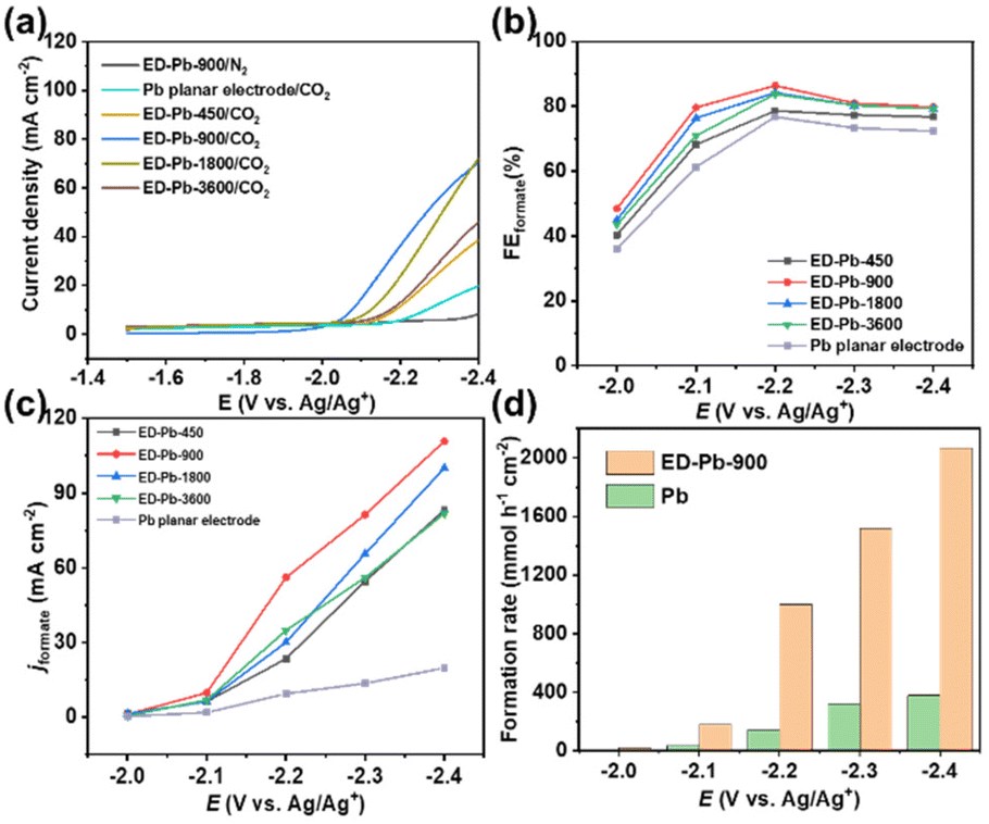 | ||
| Fig. 2 (a) The LSV curves of ED-Pb electrodes and the Pb planar electrode in CO2 or N2-saturated 30 wt% [Bmim][PF6]/AcN-H2O (5 wt%) electrolyte (temperature: 25 ± 3 °C, without stirring). (b) The FEformate and (c) jformate values of the ED-Pb electrodes and the Pb planar electrode at various applied potentials (temperature: 25 ± 3 °C, with stirring and CO2 flow rate: 30 mL min−1). (d) The formate formation rate of the ED-Pb-900 and Pb planar electrodes at different applied potentials. | ||
The relationship between FEformate and the applied potential of all the Pb electrodes is exhibited in Fig. 2b. The applied potential and formate selectivity showed a typical volcano-trend variation. The FEformate of ED-Pb-900 ranges from 40% to 86.4% depending on the applied potential, which is higher than the FEformate of the Pb planar electrode and other ED-Pb electrodes. As the overpotential increased, the peak FEformate of the ED-Pb-900 electrode was 86.4% at the optimal potential (−2.2 V), while the side products were CO (7.84%) and H2 (0.78%). The FEformate of other ED-Pb electrodes at the optimal potential (−2.2 V) ranged from 76.9% to 84%, and the FE values of other electroreduction products are displayed in Fig. S10.† When the applied potential is more negative, it is conducive to the hydrogen evolution reaction inhibiting the production of formate. Current density is another important parameter to evaluate the CO2RR activity. The increasing relationship between jformate and applied potential is shown in Fig. 2c. ED-Pb-900 exhibited the highest jformate, and the jformate value of 110.8 mA cm−2 at −2.4 V is approximately 1.3, 1.1, 1.4, and 5.6 times higher than those for ED-Pb-450 (83.2 mA cm−2), ED-Pb-1800 (100.6 mA cm−2), ED-Pb-3600 (81.8 mA cm−2), and Pb planar electrodes (19.8 mA cm−2), respectively. It is worth noting that the formate formation rate of ED-Pb-900 (1022.2 μmol h−1 cm−2) is much larger than that of the Pb planar electrode (141.4 μmol h−1 cm−2) at −2.2 V and a superior formate formation rate of ED-Pb-900 (2067.2 μmol h−1 cm−2) is obtained at −2.4 V (Fig. 2d). According to Fig. S11,† the equilibrium potential for formate is −1.68 V vs. Ag/Ag+ in the 30 wt% [Bmim][PF6]/AcN/H2O (5 wt%) electrolyte. Therefore, the overpotential of ED-Pb-900 in the IL electrolyte system is 0.52 V when it reaches the maximum FEformate with the highest energy efficiency of 48.5% (Fig. S12†). In summary, these results indicated that ED-Pb-900 has a higher CO2 electroreduction current density and better selectivity of formate than the Pb planar electrode. Compared with other state-of-the-art Pb-based metal catalysts (Table S1†), ED-Pb-900 shows excellent performance, especially jformate, which is much higher than most of the Pb-based metal catalysts previously reported (Fig. 3).
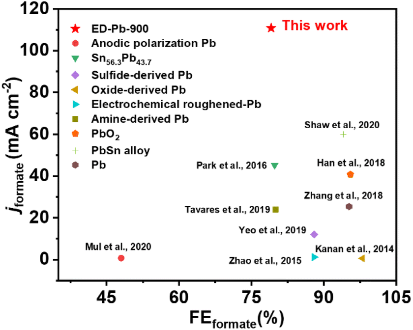 | ||
| Fig. 3 Comparison of FEformate and jformate of ED-Pb-900 with those of other Pb-based catalysts as reported in the literature. | ||
Whether the CO2 electroreduction performance of an electrode can maintain long-term stability is of great importance for practical applications. Therefore, the stability of the ED-Pb-900 electrode was measured by five sequential CO2 electroreduction experiments under corresponding optimal potentials in the [Bmim][PF6]/AcN/H2O electrolyte (Fig. S13†). The results indicated that there is no obvious decay in either FEformate or jformate during the stability test. The XRD and SEM results after the electroreduction experiments indicated that the crystal structure and the morphology of ED-Pb-900 remained unchanged (Fig. S14†). These experimental results further confirmed the excellent stability of the ED-Pb-900 electrode.
To quantitatively analyze and understand the catalytic performance of Pb-based electrodes, the electrochemically active surface area (ECSA) of the ED-Pb electrodes and the Pb planar electrode was calculated (Fig. S15–S19†). The ECSA of ED-Pb-900 (16.1 μF cm−2) was 4.73-fold higher than that of the Pb planar electrode (3.4 μF cm−2) (Fig. 4a), suggesting that the electrolysis-deposition process can significantly increase the number of exposed active sites, which is beneficial to improve the current density of the CO2RR.51 Electrochemical impedance spectroscopy (EIS) experiments were performed to investigate the effect of ED-Pb electrodes on the kinetics of the CO2RR (Fig. 4b). It was found that the Rct of ED-Pb-900 (0.49 Ω cm−2) is 78% lower than that of the Pb planar electrode (2.3 Ω cm−2), which is the smallest value among the ED-Pb electrodes. The lower Rct value of ED-Pb-900 indicated a faster charge transfer rate between the electrode and electrolyte, implying that the adsorbed CO2 molecules easily obtain electrons to form intermediates. Therefore, tuning the structure of ED-Pb electrodes can efficiently enhance the ECSA and decrease the interfacial charge transfer of the CO2RR.
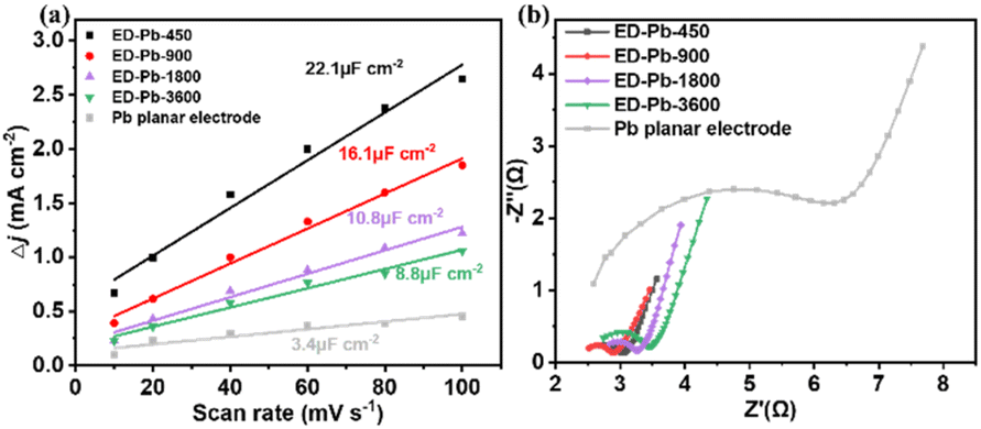 | ||
| Fig. 4 (a) Charging current density differences plotted against scan rate and (b) the Nyquist diagrams of ED-Pb electrodes and the Pb planar electrode. | ||
The reaction pathway for CO2 electroreduction to formate mainly contains two steps: step 1 is the transfer of a proton–electron pair to CO2 to form the *OCHO intermediate; step 2 is the formation of formic acid/formate product from the intermediate *OCHO with a second proton–electron pair.52 To understand the mechanism underpinning the outstanding performance of ED-Pb-900, DFT calculations were performed on the reaction energetics over the Pb(111) and Pb(200) crystal facets, which include competitive *OCHO, *COOH and *H paths. Comparing the projected density of states (PDOS) of a Pb atom on Pb(111) with that on Pb(200) before *OCHO adsorption, the position of the d-band center for Pb(111) is closer to the Fermi level than that of Pb(200), indicating that Pb(111) is more favorable to the binding and activation of CO2 (Fig. 5a). The optimized configurations of *OCHO and *COOH intermediates on the Pb(111) and Pb(200) crystal facets are displayed in Fig. S20.† The *OCHO intermediates were adsorbed on both crystal facets via two oxygen atoms. The bond lengths and angles of the optimized configuration of intermediates are summarized in Table S2.† As shown in Fig. 5b, Pb(111) exhibited the most negative adsorption energy on the *OCHO intermediate, which indicated that Pb(111) is favored to stabilize *OCHO, which is beneficial to decrease the onset potential and enhance selectivity of formate. In addition, the Pb(111) crystal facet (0.299 eV) showed a lower free energy barrier for formate formation than the Pb(200) crystal facet (0.398 eV), which meant that the Pb(111) crystal facet is more energy-favorable for producing formate (Fig. 5c and d). Furthermore, the free energy diagram of competitive *H and *COOH intermediates is also provided as a descriptor as shown in Fig. 5c and d. The relatively high free energy barriers of *H and *COOH intermediates on the two Pb crystal facets indicated that they are not conducive to the occurrence of the hydrogen evolution reaction and CO2 electroreduction to CO. To further explore the interaction between the Pb(111) crystal facet and these intermediates, we calculated the DOS of the *OCHO and *COOH intermediates adsorbed on Pb(111). The PDOS of the O atom in the adsorption of *OCHO and *COOH by Pb(111) were analyzed by decomposing the electron density and the wave function into the atomic orbital contributions. As shown in Fig. S21,† large overlaps between the O of *OCHO and Pb atoms of the Pb(111) surface indicated that Pb(111) has a strong interaction effect with the O atom in the *OCHO intermediates, which contributes to the absorption and stabilization of the *OCHO intermediates on the Pb(111) crystal facet. In summary, ED-Pb-900 with more Pb(111) crystal facets than Pb(200) crystal facets shows higher CO2RR activity.
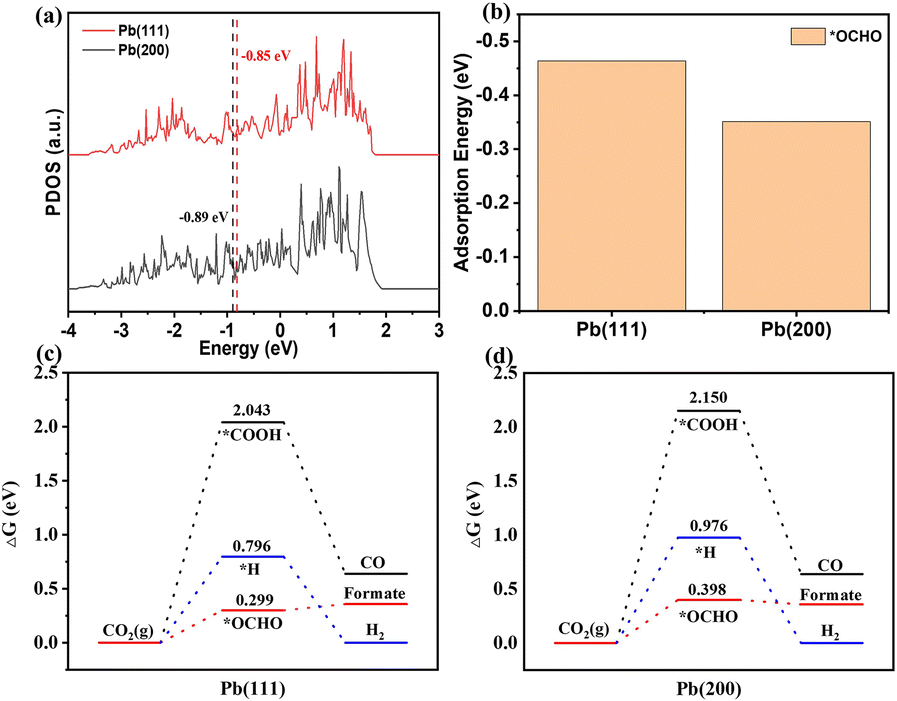 | ||
| Fig. 5 (a) Projected density of states of Pb(111) and Pb(200). (b) The adsorption energies of *OCHO on Pb(111) and Pb(200). Calculated Gibbs free energy diagrams of *OCHO, *COOH, and *H on (c) Pb(111) and (d) Pb(200). | ||
Conclusions
In this work, the IL-based electrolysis-deposition preparation of Pb electrodes for effectively promoting CO2 electroreduction to formate was proposed and proved by experiments and simulation calculations. The electrolysis-deposition process depends on the composition of the electrolyte. The halogen-containing IL electrolytes could promote the oxidation of Pb to Pb2+ and the ED-Pb electrodes with different relative peak intensity ratios were prepared by altering the deposition conditions. Therefore, due to the low surface energy of Pb(111) and the low adsorption energy of [Bmim][TFA] on Pb(111), ED-Pb electrodes have a dominant Pb(111) crystal facet. The performance of the CO2RR to formate was gradually improved with increasing I111:I200 of the ED-Pb electrodes. At −2.4 V, compared with the Pb planar electrode (70% FE, 19.8 mA cm−2), ED-Pb-900 had significantly improved CO2RR performance (80.0% FE, 110.8 mA cm−2). In particular, an excellent formate formation rate of up to 2067.2 μmol h−1 cm−2 at −2.4 V was obtained for ED-Pb-900, which is 5.6 times higher than that of the Pb planar electrode. Based on the relationship between the structures and electrochemical activity, the excellent performance of ED-Pb electrodes was attributed to the preferential exposure of the Pb(111) crystal facet, the larger electrochemically active surface area, and the lower interfacial charge-transfer resistance. The DFT calculation results proved that the free energy of *OCHO on Pb(111) (0.299 eV) is smaller than that on Pb(200) (0.398 eV), resulting in a high intrinsic activity for CO2 electroreduction to formate. This electrolysis-deposition strategy provides a new and efficient method of modifying catalysts for the CO2RR.Conflicts of interest
The authors declare no conflict of interest.Acknowledgements
This work was supported by the National Key R&D Program of China (2020YFA0710200), the National Natural Science Foundation of China (21890764, 21838010 and 22122814), the Youth Innovation Promotion Association of the Chinese Academy of Sciences (2018064), the Instrument Developing Project of the Chinese Academy of Sciences (YJKYYQ20200062), the 2021 Industrial Technology Basic Public Service Platform Project—Public Service Platform for Emission Peak and Carbon Neutral of Key Raw Material Industries (2021-H029-1-1), and the State Key Laboratory of Multiphase Complex Systems, Institute of Process Engineering, Chinese Academy of Sciences (No. MPCS-2022-A-03).References
- X. Zhang, G. Ren, C. Zhang, J. Xue, Q. Zhao, R. Li, Y. Wang and C. Fan, Green Energy Environ., 2021, 6, 693–702 CrossRef CAS.
- F. Chang, G. Zhan, Z. Wu, Y. Duan, S. Shi, S. Zeng, X. Zhang and S. Zhang, ACS Sustainable Chem. Eng., 2021, 9, 9045–9052 CrossRef CAS.
- B. Shao, Y. Zhang, Z. Sun, J. Li, Z. Gao, Z. Xie, J. Hu and H. Liu, Green Chem. Eng., 2022, 3, 189–198 CrossRef.
- A. Paulillo, M. Pucciarelli, F. Grimaldi and P. Lettieri, Green Chem., 2021, 23, 6639–6651 RSC.
- C. Jiang, J. Feng, S. Zeng and X. Zhang, Chin. Sci. Bull., 2020, 66, 716–727 CrossRef.
- J. Feng, S. Zeng, J. Feng, H. Dong and X. Zhang, Chin. J. Chem., 2018, 36, 961–970 CrossRef CAS.
- J. Feng, H. Gao, L. Zheng, Z. Chen, S. Zeng, C. Jiang, H. Dong, L. Liu, S. Zhang and X. Zhang, Nat. Commun., 2020, 11, 4341 CrossRef PubMed.
- H. Liu, B. Miao, H. Chuai, X. Chen, S. Zhang and X. Ma, Green Chem. Eng., 2022, 3, 138–145 CrossRef.
- D.-G. Yu and L.-N. He, Green Chem., 2021, 23, 3499 RSC.
- P. Ding, H. Zhao, T. Li, Y. Luo, G. Fan, G. Chen, S. Gao, X. Shi, S. Lu and X. Sun, J. Phys. Chem. A, 2020, 8, 21947–21960 CAS.
- C. Peng, X. Wu, G. Zeng and Q. Zhu, Chem. – Asian J., 2021, 16, 1539–1544 CrossRef CAS PubMed.
- Y. Tian, D. Li, C. Li, J. Liu, J. Wu, G. Liu and Y. Feng, Chem. Eng. J., 2021, 414, 128671 CrossRef CAS.
- Q. G. Zhu, J. Ma, X. C. Kang, X. Sun, H. Liu, J. Hu, Z. Liu and B. Han, Angew. Chem., Int. Ed., 2016, 55, 9012–9016 CrossRef CAS PubMed.
- J. D. Watkins and A. B. Bocarsly, ChemSusChem, 2014, 7, 284–290 CrossRef CAS PubMed.
- Z. Yang, F. E. Oropeza and K. H. L. Zhang, APL Mater., 2020, 8, 060901 CrossRef CAS.
- Z. He, J. Shen, Z. Ni, J. Tang, S. Song, J. Chen and L. Zhao, Catal. Commun., 2015, 72, 38–42 CrossRef CAS.
- W. Yu, L. Wen, J. Gao, S. Chen, Z. He, D. Wang, Y. Shen and S. Song, Chem. Commun., 2021, 57, 7418–7421 RSC.
- H. Wang, Y. Chen, X. Hou, C. Ma and T. Tan, Green Chem., 2016, 18, 3250–3256 RSC.
- C. Chen, Y. Li, S. Yu, S. Louisia, J. Jin, M. Li, M. B. Ross and P. Yang, Joule, 2020, 4, 1688–1699 CrossRef CAS.
- F. Yang, H. Yu, X. Mao, Q. Meng, S. Chen, Q. Deng, Z. Zeng, J. Wang and S. Deng, Chem. Eng. J., 2021, 425, 131661 CrossRef CAS.
- P. Yue, Q. Fu, J. Li, L. Zhang, L. Xing, Z. Kang, Q. Liao and X. Zhu, Chem. Eng. J., 2021, 405, 126975 CrossRef CAS.
- H. Wu, J. Song, C. Xie, Y. Hu and B. Han, Green Chem., 2018, 20, 1765–1769 RSC.
- R. M. Arán-Ais, F. Scholten, S. Kunze, R. Rizo and B. R. Cuenya, Nat. Energy, 2020, 5, 317–325 CrossRef.
- J. Feng, L. Zheng, C. Jiang, Z. Chen, L. Liu, S. Zeng, L. Bai, S. Zhang and X. Zhang, Green Chem., 2021, 23, 5461–5466 RSC.
- P. P. Guo, Z. H. He, S. Y. Yang, W. Wang, K. Wang, C. C. Li, Y. Y. Wei, Z. T. Liu and B. Han, Green Chem., 2022, 24, 1527–1533 RSC.
- P. De Luna, R. Quintero-Bermudez, C. T. Dinh, M. B. Ross, O. S. Bushuyev, P. Todorović, T. Regier, S. O. Kelley, P. Yang and E. H. Sargent, Nat. Catal., 2018, 1, 103–110 CrossRef CAS.
- M. Fan, S. Garbarino, G. A. Botton, A. C. Tavares and D. Guay, J. Mater. Chem. A, 2017, 5, 20747–20756 RSC.
- Q. Zhu, D. Yang, H. Liu, X. Sun, C. Chen, J. Bi, J. Liu, H. Wu and B. Han, Angew. Chem., Int. Ed., 2020, 59, 8896–8901 CrossRef CAS PubMed.
- J. Q. Feng, H. S. Gao, J. P. Feng, L. Liu, S. Zeng, H. Dong, Y. Bai, L. Liu and X. P. Zhang, ChemCatChem, 2019, 12, 926–931 CrossRef.
- J. Feng, S. Zeng, H. Liu, J. Feng and H. Gao, ChemSusChem, 2018, 11, 3191–3197 CrossRef CAS PubMed.
- S. K. Shukia, S. G. Khokarale, T. Q. Bui and J. P. T. Mikkola, Front. Mater., 2019, 6, 42 CrossRef.
- Y. Yang, H. Gao, J. Feng, S. Zeng, L. Liu, L. Liu, B. Ren, T. Li, S. Zhang and X. Zhang, ChemSusChem, 2020, 13, 4900–4905 CrossRef CAS PubMed.
- X. Sun, Q. Zhu, X. Kang, H. Liu, Q. Qian, J. Ma, Z. Zhang, G. Yang and B. Han, Green Chem., 2017, 19, 2086–2091 RSC.
- Q. Gong, P. Ding, M. Xu, X. Zhu, M. Wang, J. Deng, Q. Ma, N. Han, Y. Zhu, J. Lu, Z. Feng, Y. Li, W. Zhou and Y. Li, Nat. Commun., 2019, 10, 2807 CrossRef PubMed.
- R. Feng, Q. Zhu, M. Chu, S. Jia, J. Zhai, H. Wu, P. Wu and B. Han, Green Chem., 2020, 22, 7560–7565 RSC.
- J. Liu, P. Li, J. Bi, Q. Zhu and B. Han, Chemistry, 2022, 28, e202200242 CAS.
- Q. Zhu, D. Yang, H. Liu, X. Sun, C. Chen, J. Bi, J. Liu, H. Wu and B. Han, Angew. Chem., Int. Ed., 2020, 59, 8896–8901 CrossRef CAS PubMed.
- B. Ren, G. Wen, R. Gao, D. Luo, Z. Zhang, W. Qiu, Q. Ma, X. Wang, Y. Cui, L. Ricardez-Sandoval, A. Yu and Z. Chen, Nat. Commun., 2022, 13, 2486 CrossRef CAS PubMed.
- Z. Li, B. Sun, D. Xiao, Z. Wang, Y. Liu, Z. Zheng, P. Wang, Y. Dai, H. Cheng and B. Huang, Angew. Chem., Int. Ed., 2023, 62, e202217569 CAS.
- P. Ramachandran, K. V. Venkateswaran and V. Nandakumar, Bull. Electrochem., 1996, 12, 346–348 CAS.
- X. C. Zhong, R. X. Wang, Q. S. Liu, L. X. Jiang, X. J. Lv, Y. Q. Lai and J. Li, Chin. J. of Nonferrous Met., 2018, 28, 792–801 Search PubMed.
- D. Wu, D. J. Solanki, J. L. Ramirez, W. Yang, A. Joi, Y. Dordi, N. Dole and S. R. Brankovic, Langmuir, 2018, 34, 11384–11394 CrossRef CAS PubMed.
- Z. Cai, J. Wang, Z. Lu, R. Zhan, Y. Ou, L. Wang, M. Dahbi, J. Alami, J. Lu, K. Amine and Y. Sun, Angew. Chem., Int. Ed., 2022, 61, e202116560 CAS.
- Y. Zhao, X. Tan, W. Yang, C. Jia, X. Chen, W. Ren, S. C. Smith and C. Zhao, Angew. Chem., Int. Ed., 2020, 59, 21493–21498 CrossRef CAS PubMed.
- H. Zhong, Y. Qiu, X. Li, L. Pan and H. Zhang, J. Energy Chem., 2021, 55, 236–243 CrossRef CAS.
- J. E. Pander, J. W. J. Lum and B. S. Yeo, J. Phys. Chem. A, 2019, 7, 4093–4101 CAS.
- Z. Zeng, P. Barai, S. Y. Lee, J. Yang, X. Zhang, W. Zheng, Y. S. Liu, K. C. Bustillo, P. Ercius, J. Guo, Y. Cui, V. Srinivasan and H. Zheng, Nano Energy, 2020, 72, 104721 CrossRef CAS.
- P. Grosfils and J. F. Lutsko, Crystals, 2020, 11, 4 CrossRef.
- G. Wang, T. Liu, X. Fu, Z. Wu, M. Liu and X. Xiong, Chem. Eng. J., 2021, 414, 128698 CrossRef CAS.
- Y. Zhang, Z. Huang, K. Wu, F. Yu, M. Zhu, G. Wang, G. Xu, M. Wu, H. K. Liu, S. X. Dou and C. Wu, Chem. Eng. J., 2022, 430, 133042 CrossRef CAS.
- D. Li, J. Wu, T. Liu, J. Liu, Z. Yan, L. Zhen and Y. Feng, Chem. Eng. J., 2019, 375, 122024 CrossRef CAS.
- Y.-H. Wang, W.-J. Jiang, W. Yao, Z.-L. Liu, Z. Liu, Y. Yang and L.-Z. Gao, Rare Met., 2021, 40, 2327–2353 CrossRef CAS.
Footnote |
| † Electronic supplementary information (ESI) available. See DOI: https://doi.org/10.1039/d2gc04622a |
| This journal is © The Royal Society of Chemistry 2023 |