
 Open Access Article
 This Open Access Article is licensed under a Creative Commons Attribution-Non Commercial 3.0 Unported Licence
Advances and challenges in scalable carbon dioxide electrolysis
Ji Wei
Sun
a,
Huai Qin
Fu
b,
Peng Fei
Liu
 a,
Aiping
Chen
a,
Porun
Liu
b,
Hua Gui
Yang
*a and
Huijun
Zhao
*b
a,
Aiping
Chen
a,
Porun
Liu
b,
Hua Gui
Yang
*a and
Huijun
Zhao
*b
aKey Laboratory for Ultrafine Materials of Ministry of Education, Shanghai Engineering Research Center of Hierarchical Nanomaterials, School of Materials Science and Engineering, East China University of Science and Technology, Shanghai 200237, China. E-mail: hgyang@ecust.edu.cn
bCentre for Catalysis and Clean Energy, Gold Coast Campus, Griffith University, Gold Coast, QLD 4222, Australia. E-mail: h.zhao@griffith.edu.au
First published on 3rd September 2023
Abstract
The electrochemical CO2 reduction reaction (CO2RR) is an effective way of utilizing carbon and can be economically profitable by converting captured CO2 into valuable products. In the last decade, significant research efforts have been dedicated to CO2RR technology and significant breakthroughs in materials design, mechanistic understanding and device applications have been made. Although laboratory-level CO2RR performance has shown its potential prospects, scalable CO2 electrolysis is still far from market ready. The keys for industrialization are to cut running costs, increase the CO2 conversion rate and obtain high industrial value reaction products. Here, we start by systematically introducing the current research progress made in CO2 electrolyzer development in terms of the device structure and reaction environments. Then, the current problems in the scale-up process and corresponding solutions are summarized. Some improvement strategies and development directions are proposed, for example, cathodic salting, the use of ion exchange membranes and flow channel design. This perspective illustrates the importance of practical electrolyzers, which will guide the design of scalable CO2 electrolyzers and accelerate the commercialization process of CO2RR technology.
 Ji Wei Sun | Ji Wei Sun received his BSc degree from the Shandong University of Science and Technology in 2019. He is currently a PhD candidate under the supervision of Prof. Hua Gui Yang in the school of materials science and engineering at the East China University of Science and Technology. His current research interests are focused on the design of membrane electrode assemblies and the fabrication of advanced catalysts for carbon dioxide electrolysis. |
 Hua Gui Yang | Hua Gui Yang received his PhD from the National University of Singapore in 2005. He joined the University of Queensland in 2007 as a Postdoctoral Research Fellow. After finishing his postdoctoral training, he came back to China and took a professorship at the East China University of Science and Technology at the end of 2008. His main research interests are focused on the rational design and fabrication of functional materials for solar fuels. |
 Huijun Zhao | Prof. Huijun Zhao is the director of the Centre for Catalysis and Clean Energy, Griffith University, Fellow of the Australian Academy of Science (FAA), Fellow of the Australian Academy of Technological Sciences (FTSE), Fellow of Royal Society of Chemistry (FRSC), Fellow of the Royal Australian Chemical Institute (FRACI), and the winner of the 2016 R. H. Stokes Medal. He has extensive and valuable experience in diversified research fields including applied electrochemistry, analytical chemistry, photocatalysis, surface chemistry, energy storage materials and nanomaterials. |
Broader contextThe carbon dioxide reduction reaction (CO2RR) is an important form of carbon utilization that has received widespread attention because of its simplicity of operation, product selectivity, and use of renewable electricity. Currently, significant breakthroughs have been achieved in materials design, mechanistic understanding and device applications. However, little attention has been paid to scalable electrocatalytic CO2 reduction. As an important bridge for the transition from laboratory level to industrialization, scalable CO2 electrolysis is crucial in improving CO2 conversion ability and realizing long-term, large-scale generation of chemicals and fuels. Therefore, in this perspective, we introduce scalable electrolyzer design in terms of electrolyzer types and reaction environment factors, and highlight problems and corresponding solutions in the scale-up of these cells. Finally, strategies are proposed for the development of scalable electrolyzers in terms of cathodic salting, the use of ion exchange membranes and flow channel design. |
1. Introduction
The massive burning of fossil fuels has resulted in a dramatic increase in global atmospheric CO2 concentration, increasing from 317 ppm in 1960 to 420 ppm in 2023. This change has led to a series of problems, such as global climate change, ocean acidification, deterioration of human health and an energy crisis.1–3 Therefore, reducing atmospheric CO2 concentration has become one of the most urgent problems for humankind. Carbon capture, utilization and storage (CCUS) is considered to be a key technological alternative for global decarbonization.4–7 Studies from some researchers have suggested that CCUS may reduce carbon emissions by as much as 32% by 2050.8 However, the development of CCUS is blocked, mainly due to the cost of carbon capture and storage (CCS) processes. These processes involve the capture of CO2 gas from industries such as thermal power, cement and steel, followed by transportation of supercritical CO2 to selected underground strata through pipelines or storage tanks for permanent sequestration.9–11 The capital investment required for a typical centralized CCS facility is $1 billion, but sequestering CO2 in the ground usually needs additional investment in transportation pipelines and infrastructure.12,13 On the contrary, carbon utilization, the key process of CCUS, can be economically profitable by converting captured CO2 into economically valuable raw materials.14–16An efficient way to utilize carbon, electrochemical CO2 reduction reactions (CO2RR) have received much attention in the past decade (Fig. 1). The main reasons for this can be outlined as follows:17,18 (1) renewable electricity can be used as the source of energy for the reaction; (2) the reaction can be performed at room temperature and atmospheric pressure; (3) the reduction products are economically valuable and their selectivity depends on the catalyst design; and (4) the reaction system is simple and shows prospects for use in large-scale applications. The CO2RR involves complex mechanisms due to multiple proton-coupled electron transfer processes, high overpotentials and low selectivity for a single product. Nevertheless, great breakthroughs have been achieved on fundamental catalyst design and mechanism understanding, which have significantly improved the reaction rate, product selectivity, carbon utilization efficiency and stability.19,20 For example, Qiao et al.21 achieved the conversion of CO2 to multiple carbon products at ampere-level current densities on copper-based catalysts modulated by a series of heteroatoms (e.g. N, P, S, O). At a current density (J) of −1.1 A cm−2, the Faraday efficiency (FE) for C2+ products reached 73.7%, indicating high product selectivity can be achieved at high current densities. Gewirth et al.22 prepared Cu-polyamine hybrid catalysts via a co-plating method to drive CO2-to-C2H4 conversion. The FE of C2H4 was 87% ± 3% at −0.47 V (vs. RHE), the highest value reported so far, and the full cell energy efficiency reached 50% ± 2%. Sargent et al.23 achieved a single CO2 utilization of up to 77% in a strongly acidic electrolyte by modifying ionic polymers on the surface of copper electrodes, the highest conversion available for generating multi-carbon products. Masel et al.24 achieved 1000 h of operation at a J of 200 mA cm−2 in a membrane electrode (one of the best CO2RR stabilities) by functionalizing an anion exchange membrane with imidazole-based ionic liquids, using Ag as a catalyst.
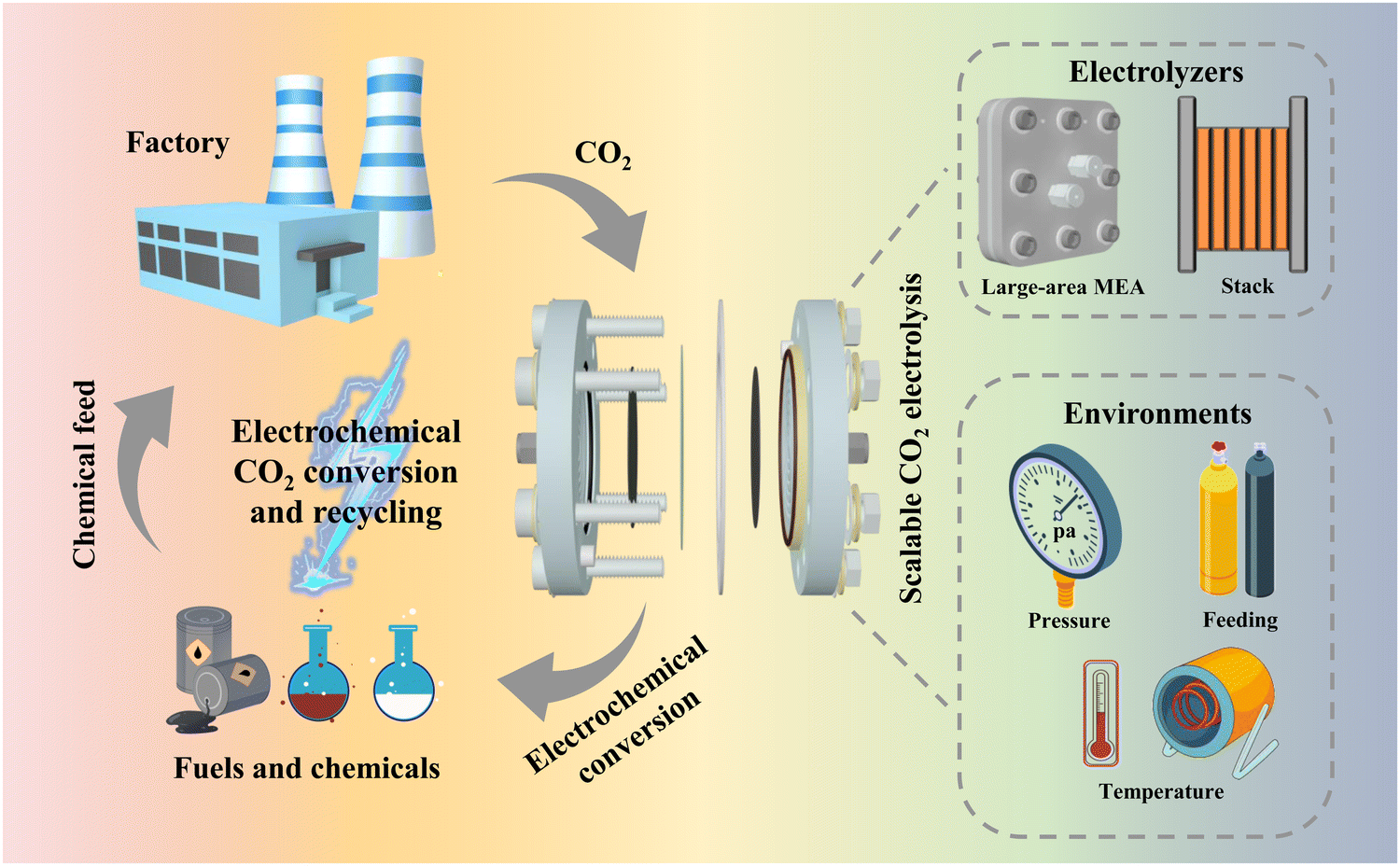 | ||
| Fig. 1 Schematic diagram of the use of the CO2RR for carbon recycling and the design of electrolyzer strategies and environments to realize scalable CO2 electrolysis. | ||
The above-mentioned reports indicate that catalyst-related laboratory-scale CO2 electrocatalytic reduction is becoming increasingly mature. However, the current electrolyzer devices that can be initially scaled up and have prospects for industrial application suffer from a number of problems, such as low current, low energy efficiency, and poor stability. These devices are far from the standard required at the industrial level and are still in the initial stage. In this regard, this perspective illustrates the importance of scalable electrolyzers through techno-economic accounting (TEA), and introduces some existing electrolyzers that are expected to be industrialized. These electrolyzers are classified by electrolyzer type and reaction environment factors (Fig. 1), for example, large-area electrolyzers, electrostacks, and high-pressure heated electrolyzers, etc. The problems in the scale-up process and some corresponding solutions are also summarized. Finally, strategies in terms of device structure, flow channel design and ion exchange membranes for the development of scalable electrolyzers are proposed.
2. Types and importance of scalable CO2 electrolyzers
2.1 CO2 electrolyzers
A CO2 electrolyzer is a device that converts CO2 into specific products driven by electricity. It is mainly composed of an electrolyzer, a catalytic electrode, ion exchange membrane and electrolyte. CO2 is reduced to high value-added chemical raw materials at the cathode, and oxygen is generated at the anode via the oxygen evolution reaction (OER).25 At present, there are three types of electrochemical cells for the CO2RR: the H-type cell, flow cell and membrane electrode assembly (MEA). Due to the differences in the electrolyzer structure and the CO2 mass transfer mode, the electrolyzers have a great impact on the current density, selectivity and stability of the catalytic reaction.26 Therefore, an in-depth exploration of the structural characteristics of different CO2 electrolyzers is of paramount significance to the development of scalable CO2 electrolyzers.The H-type cell is divided into cathode and anode reaction chambers by an ion exchange membrane. In the CO2RR process, CO2 is introduced into the electrolyte of the cathode chamber containing the working electrode. When the CO2 concentration in the electrolyte reaches saturation, it is transferred to the catalyst surface by diffusion, and thus the reduction reaction occurs.27–29 The H-type cell has become a basic tool for evaluating the performance of CO2RR electrocatalytic materials at laboratory scale due to its simple structure and easy assembly. However, H-type cells have many serious problems in scalable applications. For example, the CO2 has to be dissolved in the electrolyte before being transferred to the catalyst surface, but CO2 has a low solubility (∼33 mM at 25 °C) and diffusion rate (diffusion coefficient of 0.00194 mm2 s−1 at 25 °C) in water, leading to difficulties in CO2 transfer to the catalyst surface. In particular, a significant decrease in selectivity occurs at high current densities because the supply of CO2 does not cover demand.30–32 In addition, the catalyst is easily dislodged when immersed in the electrolyte, and stability tests cannot be run for a long time, often only a dozen hours.33,34 Therefore, H-type cells are only suitable for laboratory-scale research and cannot be scaled up for industrial applications.
Aimed at solving the problem of difficult CO2 mass transfer in the H-type cell, a flow cell with a three-phase interface has been developed to greatly improve CO2 mass transfer efficiency. Unlike the H-type cell, in the cathode chamber of the flow cell, a hydrophobic gas diffusion layer (GDL) separates the electrolyte and CO2 gas, forming a gas–liquid–solid mass transfer interface, allowing CO2 gas to pass through the GDL and reach the catalyst surface directly, thus eliminating the CO2 mass transport limitation.35–37 Therefore, this design of flow cell greatly improves the reaction rate of the CO2RR, and can reach several hundred milliamperes per square centimeter for industrial applications. However, the flow cell still has some significant problems in the scale-up process. On the one hand, the electrolyte layer between the cathode and the ion exchange membrane increases the ohmic resistance and reduces the energy efficiency of the electrolyzer, making it impossible to use a mild neutral electrolyte. If a strong alkaline electrolyte is used, it will aggravate the corrosion of the device, CO2 loss and salt precipitation; on the other hand, since the layer of catalyst coated on the GDL is in direct contact with the electrolyte, the GDL will be broken down over long operating time, flooding the electrodes with electrolyte and leading to a serious decrease in selectivity. Therefore, based on the above problems, it is difficult for the flow cell to be scaled up at present.
To solve the problems in a flow cell, new scalable electrolyzers must be developed to meet industrialization requirements. In recent years, MEA-type electrolyzers have been applied to CO2RR research inspired by fuel cells and water electrolyzers. Unlike in a flow cell, there is no electrolyte layer between the GDL and ion exchange membrane in MEA, instead they are directly pressed together, almost eliminating the gap between the cathode catalyst, ion exchange membrane and anode catalyst.38–40 This zero-gap structure not only makes the ohmic impedance of the electrolyzer lower, but also effectively avoids the problem of GDL flooding. This structure allows for more stable and efficient CO2 conversion in the MEA device.
According to recent reports on the catalytic performance of the three CO2RR electrolyzers,41–43 MEA electrolyzers are significantly better than H-type cells and flow cells in terms of selectivity, current density and stability. In summary, MEA is currently the most promising CO2RR device for achieving industrial scale-up.
2.2 TEA analysis of scalable electrolyzers
Preliminary techno-economic studies have shown that CO2 electrolysis is economically viable, but the cost of electricity and the efficiency of the electrolyzer are the main economic barriers to industrial development. Fortunately, recent studies on renewable power generation have shown that the cost of photovoltaic power is on a significant downward trend, with prices as low as $0.03 per kW h in the near future.44 Therefore, the further development of electrolyzers is particularly important at present.Currently, MEA-based large-area electrolyzers and multi-reactor stacks have been used for scalable CO2RR electrolyzers. In a report by Jiao et al.,12 a TEA analysis of CO2 industrial electrolysis was carried out using an electrostack and single chamber electrolyzer (SC electrolyzer), respectively. Only the reduction by the electrolyzer itself and maintenance cost related to the use of the stack is considered here, and the value-added cost outside the device is not taken into account (the difference between the two would be further increased if the difference in value-added cost is considered). The cost of CO2-to-CO electrolysis was calculated to be $0.37 per kg (Fig. 2a) instead of $0.41 per kg when a three-chamber stack is used instead of a single-chamber MEA. If this cost is used to simulate the profitability of a plant with a CO production capacity of 50![[thin space (1/6-em)]](https://www.rsc.org/images/entities/char_2009.gif) 000 kg per day over a 10 year period, the plant with a single-chamber MEA would still lose about $3000000 after 10 years of operation (Fig. 2b), while the plant with a three-chamber stack would make a profit of about $5600000 (Fig. 2c). Based on the above analysis, research on scalable electrolyzers is crucial to reduce the cost of industrial application and to advance the industrialization of CO2 electrolysis.
000 kg per day over a 10 year period, the plant with a single-chamber MEA would still lose about $3000000 after 10 years of operation (Fig. 2b), while the plant with a three-chamber stack would make a profit of about $5600000 (Fig. 2c). Based on the above analysis, research on scalable electrolyzers is crucial to reduce the cost of industrial application and to advance the industrialization of CO2 electrolysis.
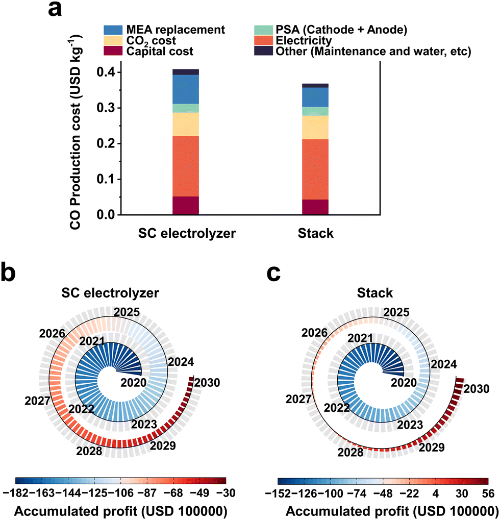 | ||
| Fig. 2 TEA of the production of CO using an SC electrolyzer and stack. (a) Cost of CO production using SC electrolyzer and stack. Simulation of the profitability of a plant with a CO production capacity of 50000 kg day−1 over a 10 year period using (b) an SC electrolyzer or (c) a stack. The TEA results indicate that the use of more scalable electrolyzers will reduce the cost of CO2 electrolysis. | ||
3. Current applications and challenges of scalable CO2 electrolysis
Initial progress on scalable electrolyzers has been made at the laboratory level. We introduce here the scalable CO2 electrolyzers reported in recent years, summarize the advantages and problems of different electrolyzers, and finally provide an outlook on the future development of scalable electrolyzers.3.1 Large-area CO2RR electrolyzer
In order to undertake CO2 electrolysis at industrial reaction rates and increase the CO2 conversion rate, a series of attempts have been made to achieve the industrial feasibility of large-area CO2 electrolyzers based on MEA electrolyzers. A large-area CO2 electrolyzer represents a parallel scaling up (enlargement of device volume and reaction area without structural change) of the reaction area compared to the laboratory-grade MEA, so it is relatively simple and easy to operate in terms of assembly and operation. Our group45 prepared a Co single-atom catalyst using a microwave method and performed CO2 electrolysis utilizing an electrolyzer with an effective reaction area of 100 cm2 (Fig. 3a–c). The selectivities of CO in this electrolyzer are over 85% in the current range of 1–10 A (Fig. 3d). In particular, at a current of 10 A and a CO2 flow rate of 150 mL min−1, the single-pass conversion efficiency (SPC) of CO2 was still as high as 40.4% (Fig. 3e), and it took only 6.2 h to generate 1 mole of CO (Fig. 3f). Wang et al.46 compared the CO2 reduction performance of electrolyzers with an active area of 4 cm2 and 100 cm2 under a neutral electrolyte. As shown in Fig. 3g and h, the current density of the small-area device is significantly higher than that of the large-area device at the same potential (e.g., at a full-cell voltage of 2.7 V, the current density of the 4 cm2 electrolyzer is about 130 mA cm−2, while that of the 100 cm2 electrolyzer is about 60 mA cm−2). This indicates that the impedance of the device itself or the electrochemical impedance of the electrolysis process increases accordingly when the electrolyzer is enlarged, leading to a drop in the current density and a decrease in the energy efficiency (EE) of the reaction. Fortunately, the decrease in current density does not affect the product selectivity, and the Faraday efficiency of CO remains close to 100% (Fig. 3i). Similar results were found in the research by Janáky et al.47 An 8 cm2 electrolyzer has a CO current density close to 600 mA cm−2 at a full cell potential of 3.2 V, while the CO current density of a 100 cm2 electrolyzer is only ∼350 mA cm−2 (Fig. 3j–l).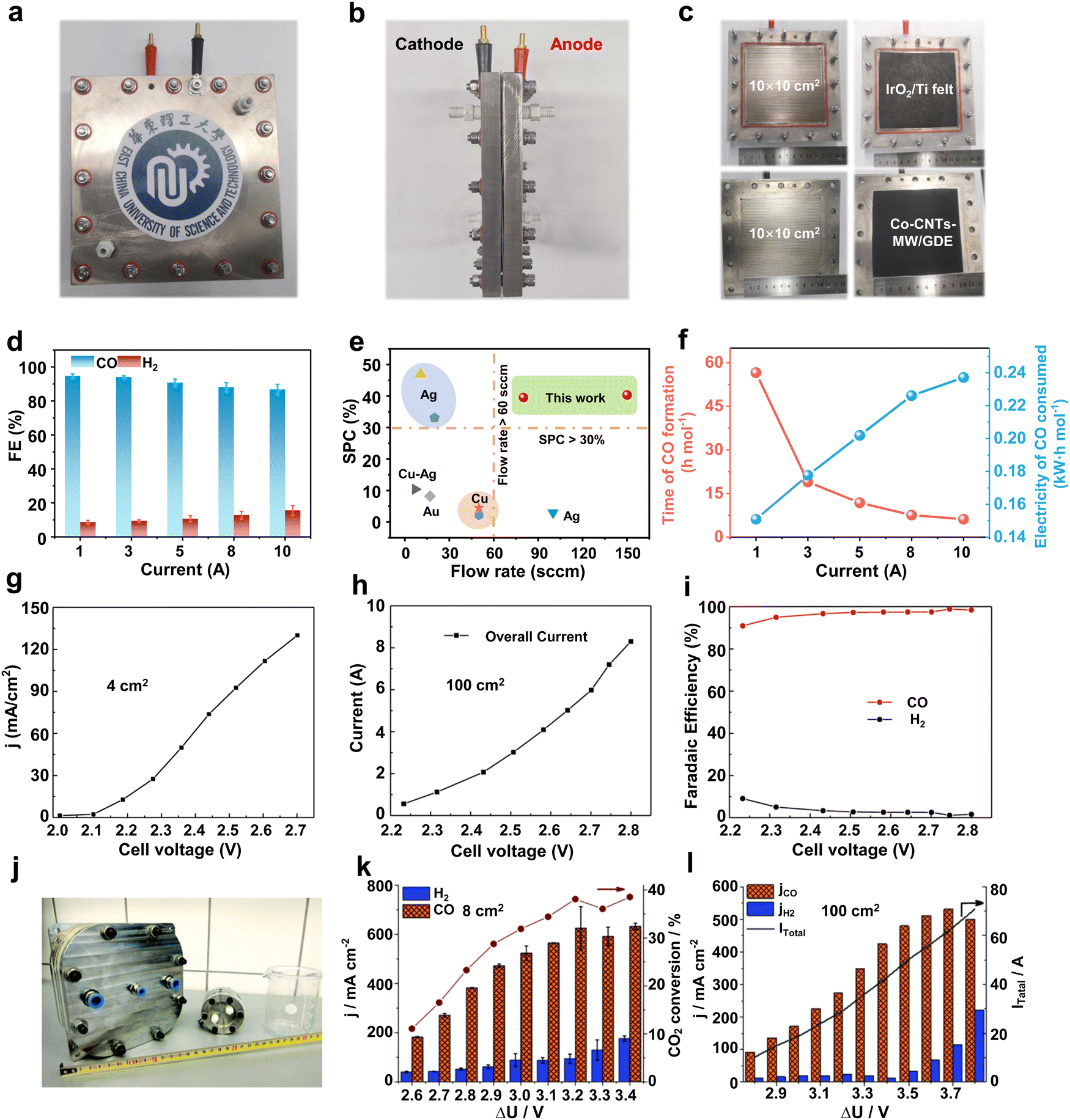 | ||
| Fig. 3 Large-area MEA electrolyzer CO2RR performance. (a) Front view, (b) side view and (c) runner view photograph of a home-made 100 cm2 MEA. (d) CO and H2 selectivity in a current range from 1 to 10 A. (e) Single-pass conversion of Co-CNTs-MW catalyst compared with various CO2RR electrocatalysts. (f) Time of CO formation and electricity of CO consumed in a 100 cm2 MEA. Reproduced with permission from ref. 45 copyright 2023, Springer Nature. Current density of a (g) 4 cm2 and (h) 100 cm2 MEA under different voltages. (i) Selectivity of CO and H2 in a 100 cm2 electrolyzer at different voltages. Reproduced with permission from ref. 46 copyright 2019, Elsevier Publishing Group. (j) Digital photo of 8 cm2 and 100 cm2 electrolyzers. CO2RR performance of (k) 8 cm2 and (l) 100 cm2 electrolyzers at different potentials. Reproduced with permission from ref. 47 copyright 2020, RSC Publishing. A large-area MEA electrolyzer can increase the CO2 electrolysis current while ensuring high product selectivity. | ||
The above findings indicate that large-area CO2 electrolyzers have important implications for improving CO2 conversion rates and achieving further industrial-grade CO2 electrolysis. However, there are still some problems related to large-area CO2 electrolyzers. For example, the ohmic resistance of the large-area electrolyzer itself increases, resulting in lower current densities and EE. Moreover, the operational stability gradually decreases due to the precipitation of carbonate blocking the active site and catalyst shedding, etc. Therefore, the future development of large-area electrolyzers should be devoted to both reducing resistance and improving stability. For the reduction of resistance, gold plating on the electrolyzer surface can be attempted.48 For the problem of carbonate precipitation blocking the active site, this is a difficulty common to MEA-type electrolytic cells at present. We will summarize a detailed solution in the subsequent part of the perspective.
3.2 CO2 electrostacks
Although large-area electrolyzers can bring higher CO2 conversion rates, they are still not compatible with industrial requirements in terms of device cost and space occupation. As an integrated electrolyzer, an electrostack allows for simultaneous CO2 conversion in multiple chambers, resulting in sufficient CO2 conversion while reducing device material costs. As shown in Fig. 4a and b, electrostacks commonly encompass two or more electrolytic chambers. Notably, each pair of these chambers is linked by means of a bipolar plate (BPP), wherein one facet of the BPP serves as the anode electrolytic chamber while the opposite facet functions as the cathode electrolytic chamber.49 From the perspective of current, the electrolytic chambers are connected in series with each other, so that the same current flows through each electrode. For the flow of CO2 gas between the electrolyzer layers, there are two types of connections: parallel and series. A parallel connection (Fig. 4a) means that the gas flows evenly through each cathode chamber, and the gas concentrations in the feed and discharge of each chamber are basically the same. A series connection (Fig. 4b) means that the CO2 enters the first cathode chamber, then the reaction products and the remaining CO2 enters the second cathode chamber, and so on, until it flows through the last cathode chamber and finally out of the cell, and thus this flow method can obtain a very high CO2 conversion rate.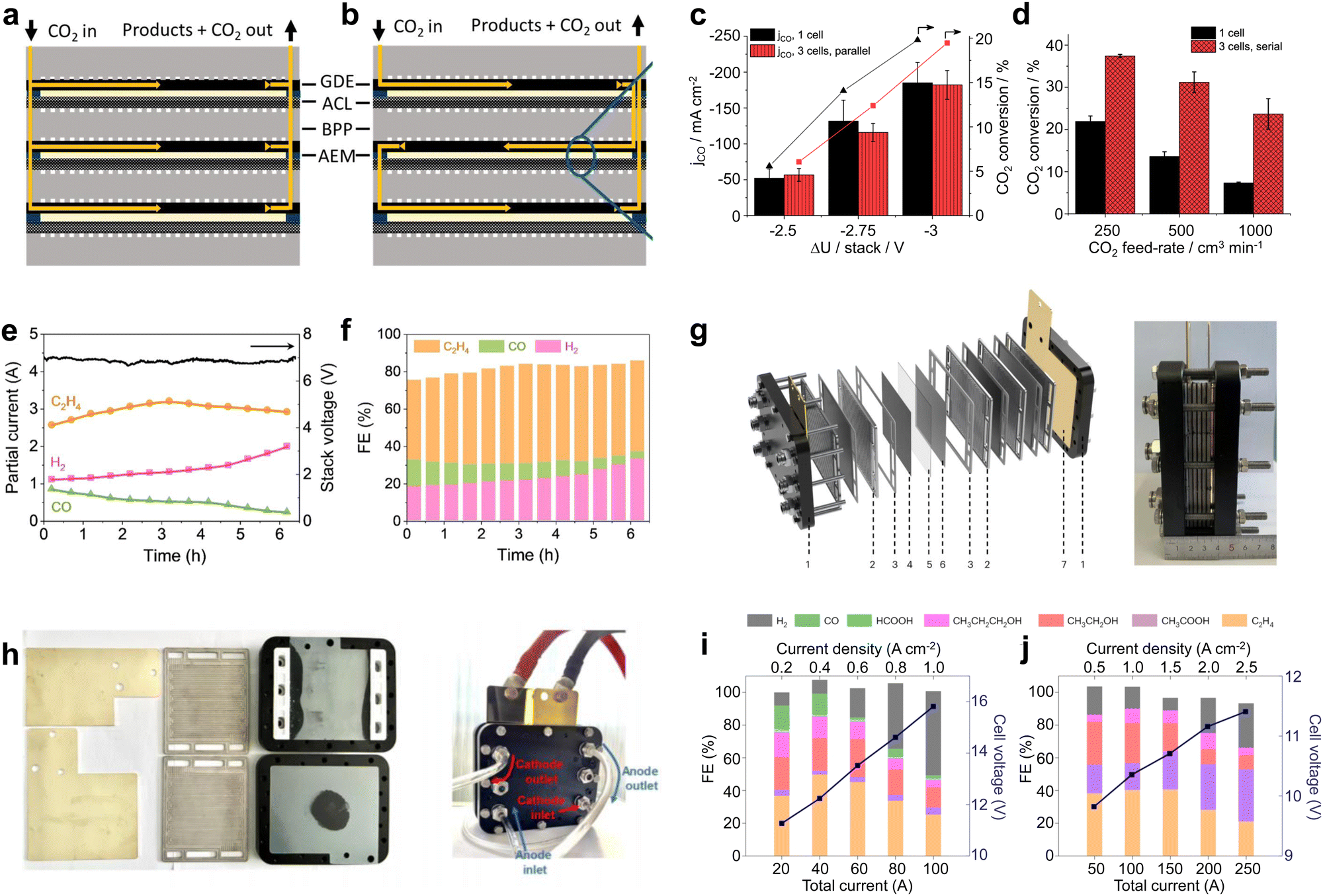 | ||
| Fig. 4 Material flow patterns and CO2RR performance in electrostacks. Circulation of CO2 in the stack: (a) parallel and (b) series circulation. (c) Current density and (d) CO2 conversion for a single-chamber electrolyzer and a three-chamber stack with an area of 61 cm2. Reproduced with permission from ref. 49 copyright 2019, American Chemical Society. (e) Potential and (f) product selectivity distribution of a three-compartment stack with an area of 10 cm2 at 6 A. Reproduced with permission from ref. 50 copyright 2021, Elsevier Publishing Group. (g) Structure schematic and digital photo of 4 × 100 cm2 electrostack. (h) Digital photos of the internal runners of the stack and during testing. FE and cell voltage as a function of applied current density measured in (i) 0.1M KOH under a pure CO2 feed and (j) 1M KOH under a pure CO feed. Reproduced with permission from ref. 51 copyright 2023, Springer Nature. The stack can realize simultaneous CO2 electrolysis in multiple electrolytic chambers, further improving the CO2 conversion capacity. | ||
In recent years, CO2 electrolyzers based on electrostacks have gradually become a hot research topic. Janáky et al.49 built a 61 cm2 three-chamber stack with gas flowing in series. In terms of current density, the three-cell stack and single-cell electrolyzer are basically consistent (Fig. 4c). However, under different CO2 feed flow rates, the three-chamber stack shows a significantly better CO2 conversion rate than the single-chamber electrolyzer (Fig. 4d), indicating that more reaction chambers and the total length of the flow paths facilitated the full utilization of CO2. Hyung-Suk Oh et al.50 designed a three-chambered electrostack with an area of 10 cm2. To reduce the voltage, the stack used iron-doped cobalt foam as the OER electrode and a KOH-incorporated Cu nanoparticle electrocatalyst deposited on the GDL as the cathode for the CO2RR. When the stack was operated at a current of 6 A, the voltage was maintained at about 7 V. This indicates that the voltage of each zero-gap electrolyzer was about 2.3–2.4 V, which is basically consistent with the electrolysis voltage of a single-chamber electrolyzer (Fig. 4e). In addition, the product selectivity of the three-chamber stack was also not attenuated compared to that of the single-chamber electrolyzer (Fig. 4f). In a 6 hour stability test, the C2H4selectivity was maintained at ∼45% with a current of ∼3 A, consuming 2.8 L of CO2 and producing 1.4 L of C2H4. Some breakthroughs have also been made in conducting high-current CO2 electrolysis in an electrostack. Bao et al.51 designed a four-chamber electrolytic stack with an area of 100 cm2 (Fig. 4g). This electrolyzer was designed to provide a parallel and uniform flow of gas through each chamber (Fig. 4h), and CO2/CO co-electrolysis was achieved using CuO nanosheet catalysts at a current of more than 100 A. The stack achieved the highest C2H4 production rate of 457.5 mL min−1 at 150 A and a CH3COOH production rate of 2.97 g min−1 at 250 A (Fig. 4i and j). The product generation rates here reached the level required for industrial application, indicating that a stack holds great promise for industrial production.
Some advances have also been made in new and industrial pilot power stacks. Kang et al.39 reported that an electrostack unit for CO2 electrolysis (Fig. 5a) to produce syngas has been pilot tested at Yitai Chemical's coal-to-oil plant in Ordos, Inner Mongolia, with a single electrolyzer voltage of only 2.8 V and an annual CO2 throughput of 30 tons per year and stability of 2000 h. Takeda et al.52 at Toyota reported a large-volume photovoltaic power electrolyzer for converting CO2 to formate. The electrolyzer contains five stacked electrodes and six single-crystal Si photovoltaic cells (∼1000 cm2) connected in series (Fig. 5b and c), which were electrolyzed by immersing the electrodes in water bubbled with CO2. The photovoltaic part of the device is well-matched to the electrocatalytic cell to produce a reaction current of 6.30 A. The overall solar-formate conversion efficiency reached 7.2% and the formate production rate reached 93.5 mmol h−1. In addition, Chen et al.53 designed a 100 cm2 stack with four electrolytic chambers (Fig. 5d and e). Unlike previous reports, the cathode chamber of this stack was fed with a CO2-saturated electrolyte. This electrolyte flows into the cathode by forced convection, and due to the reduction of pressure at the cathode, CO2 gas precipitates in situ on the catalyst surface, causing the CO2RR to occur (Fig. 5f). This design not only improves the conduction rate of CO2 and protons, but also takes away the generated carbonate in time and avoids the blockage of the reaction site.
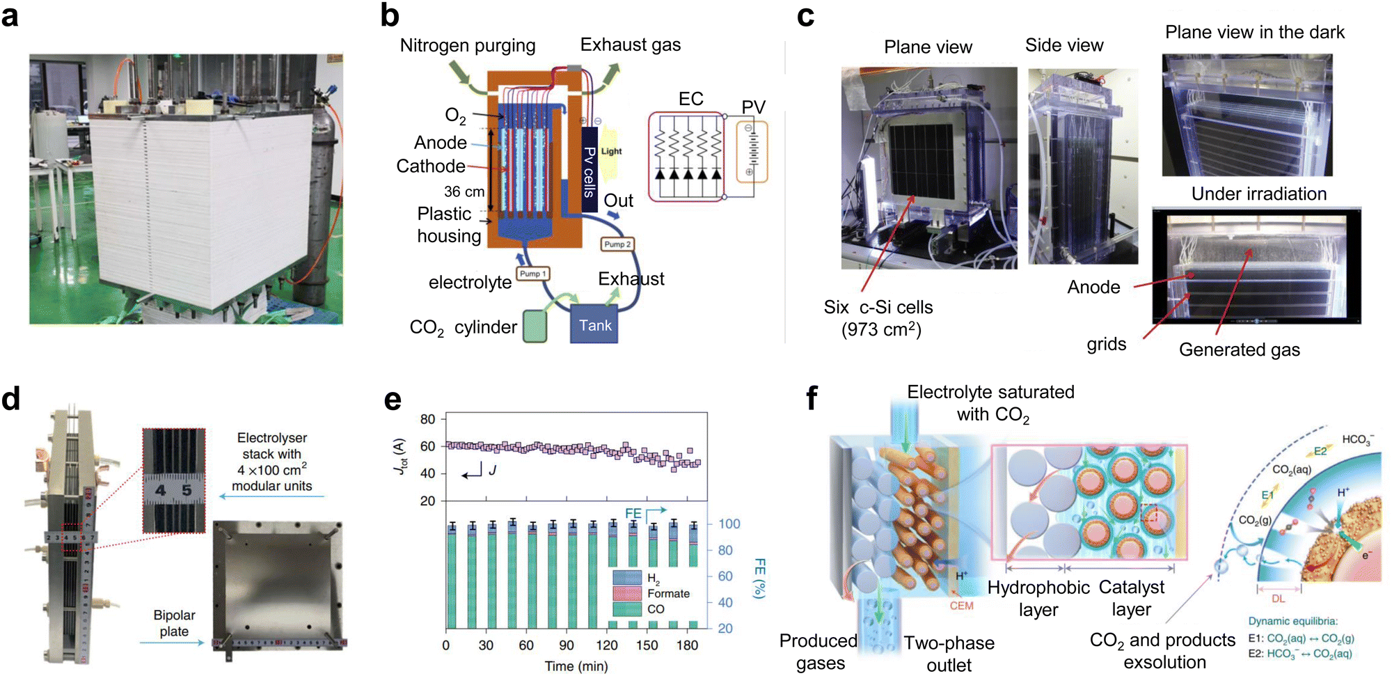 | ||
| Fig. 5 Subtly designed industrial pilot power stacks. (a) CO2 electrostack medium-scale test device. Reproduced with permission from ref. 39 copyright 2022, American Chemical Society. (b) Schematic and (c) digital photos of a large-volume photovoltaic power electrolysis cell converting CO2 to formate. Reproduced with permission from ref. 52 copyright 2021, Elsevier Publishing Group. (d) Digital photo and (e) CO2RR performance of a 100 cm2 stack with four electrolytic chambers. (f) Schematic diagram of gas precipitation in situ on the catalyst surface when CO2-saturated electrolyte is forced through the cathode. Reproduced with permission from ref. 53 copyright 2022, Springer Nature. | ||
To further illustrate the significance of scalable electrolyzers, we compared the CO product generation performance of several different electrolyzers. As shown in Table 1, when electrolysis is performed using a large area stack, it is capable of generating ∼80 L of CO per hour, far exceeding that of a laboratory-scale small area MEA.
| Electrolyzer | Catalysts | Area (cm−2) | FECO (%) | I (A) | CO generation rate (L h−1) | Ref. |
|---|---|---|---|---|---|---|
| MEA | Ni–N–C | 4.0 | ∼90.0 | ∼0.6 | 0.2 | 54 |
| Ag | 5.0 | ∼96.0 | 1.0 | 0.4 | 24 | |
| Au/C | 3.2 | 85.0 | 1.6 | 0.6 | 43 | |
| Large-area MEA | Co-CNTs-MW | 100.0 | 86.8 | 10.0 | 3.6 | 45 |
| Ni-N-C-QAPPT | 100.0 | ∼85.0 | 80.0 | 28.4 | 55 | |
| Ni-NC | 100.0 | 99.0 | 8.3 | 3.4 | 46 | |
| Ag | 100.0 | ∼80.0 | ∼85.0 | 28.4 | 56 | |
| Electrostack | Ag | 100.0 × 3 | ∼75.0 | ∼80.0 | 75.2 | 40 |
| Ag | 100.0 × 4 | ∼85.0 | 59.0 | 83.8 | 53 | |
| Ag | 61.0 × 3 | 75.0 | ∼14.2 | 13.4 | 49 |
3.3 High-pressure and heated CO2RR electrolyzers
In addition to large-area electrolyzers and electrostacks which can increase the CO2 conversion rate, some changes to the reaction environmental factors of the scaled-up electrolyzer can lead to further performance improvements, such as high-pressure and heated CO2 electrolyzers.In atmospheric electrolyzer tests, the pressure of the cathode CO2 gas is about one atmosphere. For high-pressure electrolyzers, the cathode CO2 pressure typically reaches several to even dozens of atmospheres. This heightened pressure effectively enhances the concentration of CO2 at the catalyst surface, thereby facilitating the process of CO2 mass transfer. Consequently, this augmentation contributes to elevated current densities and heightened selectivity, ultimately yielding decreased energy consumption and mitigated costs. Sinton et al.57 performed CO2 tests at 10–50 bar, under which both the current density and CO selectivity of the catalyst increased via increasing pressure (Fig. 6a–c). Sinton et al.58 achieved CO2 reduction supplied by flue gas under high pressure. This method improved the reactivity of CO2 reduction by constructing a hydrophilic layer on the catalyst surface, increasing the solubility of CO2 at high pressure, and preventing O2 from reaching the reaction site (Fig. 6d–f).
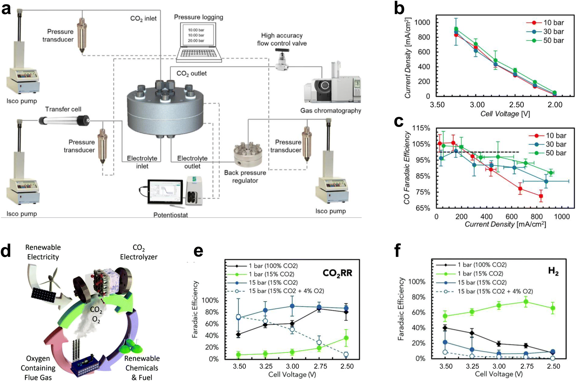 | ||
| Fig. 6 Effect of pressure on CO2 electrolyzers. (a) Schematic diagram of the structure of the high-pressure test system. (b) Product current density and (c) selectivity at different pressures. Reproduced with permission from ref. 57 copyright 2020, Elsevier Publishing Group. (d) Schematic diagram of CO2 reduction of flue gas under high pressure. Selectivity of (e) CO2RR and (f) HER under high pressure. Proper pressure facilitates CO2 mass transfer and improves the current density and selectivity of the products. Reproduced with permission from ref. 58 copyright 2020, RSC Publishing. | ||
For heated electrolyzers, the temperature is often in the tens of degrees. A proper temperature increase can reduce the impedance of the electrolyzer (Fig. 7a) and increase the conduction rate of the ions in the electrolyte (Fig. 7b), thus increasing the current density (Fig. 7c). However, when the temperature rises to a certain level, the activity of H2 gradually increases (Fig. 7d) and may also cause structural damage of the ion exchange membrane, thus resulting in a decrease in CO2 reduction performance.43,47
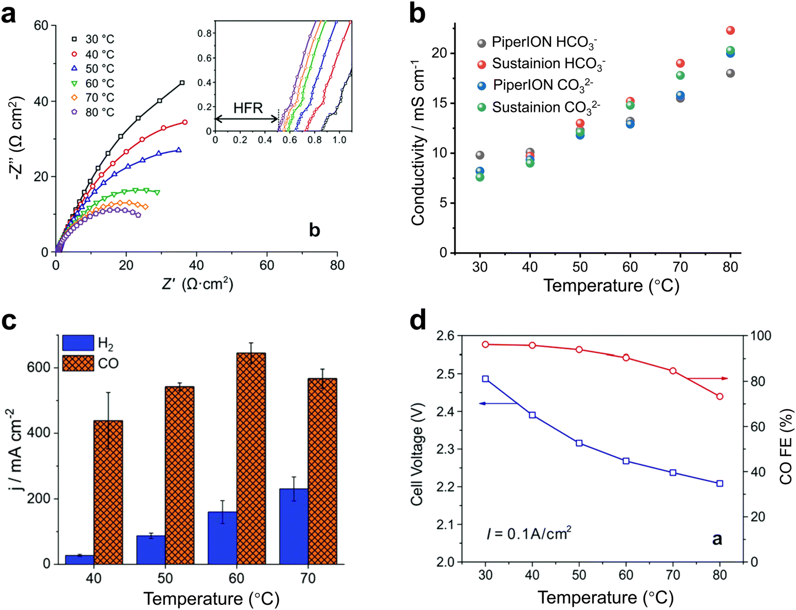 | ||
| Fig. 7 Effect of heating on CO2 electrolyzers. Effects of temperature on (a) the impedance, (b) ionic conductivity, (c) current density and (d) product selectivity of the electrolyzer. Proper temperature facilitates ion transport, reduces impedance, and increases current density. (a) and (d) Reproduced with permission from ref. 43, 47 copyright 2019, RSC Publishing. (b) and (c) Reproduced with permission from ref. 47 copyright 2020, RSC Publishing. | ||
While high-pressure and heated electrolyzers can further improve the CO2 reduction performance of amplifiable electrolyzers, this often requires the support of a more expensive pressurized or heated infrastructure. Therefore, to successfully use high-pressure and heating units for industrial-scale CO2 reduction, it is necessary to design the unit structure properly and reduce the additional costs associated with the infrastructure.
3.4 Cathode gas feeding
The use of CO2 + CO/O2 co-feed gas or flue gas in scalable CO2 electrolysis processes has also received much attention recently. This is because a reasonable adjustment of the cathode atmosphere composition will be beneficial to improve the selectivity of specific products and reduce the feed cost.Strasser et al.59 reported a mechanistic investigation of a CO2RR based on a CO2/CO co-feed over copper. When the ratio of CO2 to CO was 1:1, the yield of C2H4 was unexpectedly increased by nearly 50%. Lu et al.60 reported co-electrolysis of CO2 and low concentration O2. A small amount of oxygen reduction reaction is used to supplement hydroxyl groups on the catalyst surface, improving the selectivity of oxygen and hydrocarbon substances in the product. In addition, the use of flue gas as a source of CO2 for electrolysis can greatly reduce the feed cost. The main components of flue gas are N2, CO2 and O2. N2, due to its chemical inertness, only acts as a diluting agent for CO2. Won et al.61 demonstrated that the selectivity of the CO2RR was almost constant when the N2 content was increased, but the current density decreases when the ratio of CO2 and N2 is modulated. Unfortunately, O2 can severely inhibit CO2 electrolysis in MEA electrolyzers due to its high reduction potential.62 Takeda et al.63 reported that the selectivity of the CO2RR decreases to 20% with only 1% O2 present in the CO2 gas. Wang et al.64 achieved nearly 100% selectivity of formic acid in the presence of 5% O2 by spraying an amine-based polymer film on the reverse side of the GDE that selectively permeates CO2. Although this physical filtration method can achieve better performance, if the catalyst can be directly used to capture and transform CO2 in flue gas, the cost and GDE preparation will be further optimized. In summary, the rational use and design of the source and composition of the cathode feed is important for scalable CO2 electrolysis to reduce costs and improve product selectivity.
4. Further design of scalable electrolyzers
Based on the above electrolyzer research, further design and improvement of the scalable electrolyzer structure will facilitate the process of industrial application. Here, we summarize solutions to the carbonate precipitation problem, the use of ion exchange membranes and the design of flow channels, etc., hoping to provide reference values for industrial CO2 electrolyzers.4.1 Solutions for carbonate precipitation
Clogging of the active site by carbonate precipitation, a common problem in MEA-type electrolyzers, is a serious obstacle to the long-term operation of CO2 electrolysis.Currently, there are several typical solutions to this problem. One is to periodically clean the gas diffusion electrode (GDE) of the cathode gas chamber to flush out the carbonate produced. For example, Sargent et al.65 achieved CH4 production at 190 mA cm−2 for up to 100 h by periodically cleaning the cathode GDE with deionized water (Fig. 8a). The second method is to transfer the carbonate to the anode by electromigration at low potential under an alternating electric field. This method reduces the reaction rate to near 0 mA cm−2 at low potentials, eliminating hydroxide formation, while maintaining sufficient negative polarization at the cathode to transport carbonate ions to the anode under electromigration. Using this method, Sinton et al.66 ensured that the selectivity of the C2 product remained close to 80% after up to 236 h of electrolysis (Fig. 8b). However, this method entails additional energy losses and increased time costs. Some recent progress in CO2 electrolysis using proton exchange membranes under strongly acidic electrolytes was reported to avoid carbonate precipitation. This method allows the generated carbonate to regenerate CO2 with H+ in solution (Fig. 8c),67 effectively avoiding blockage of the reactive site. However, the elevated H2 selectivity caused by the strong acidity makes electrolysis impossible to run for a long time, which is still challenging for industrialization. The use of salt-free electrolyte solutions can fundamentally solve the salt precipitation problem, but the lack of metal cations can make CO2 activation difficult, leading to large-scale hydrogen evolution reactions (HERs). Excitingly, Zhuang et al.68 achieved high-performance CO2 electrolysis in pure water (Fig. 8d) by using porous copper modified with a quaternary polyether ether ketone (QAPEEK) containing carbonyl groups (Fig. 8e) to activate CO2 in a salt-free environment. A total current density of 1000 mA cm−2 was achieved at a cell voltage of 3.73 V (Fig. 8f). CO2 electrolysis using bipolar membranes can also alleviate carbonate production to some extent.69,70 In addition, direct electrolysis of CO2 absorbed in amine solutions using the reaction swing absorption technique can also be a good way to slow down carbonate precipitation.71,72 This is because the amine solution flowing through the cathode side can carry away the carbonate produced in time. In conclusion, one way to solve the carbonate precipitation problem is to clean or convert the generated carbonate in time, and the other is to avoid the use of salt-containing electrolytes.
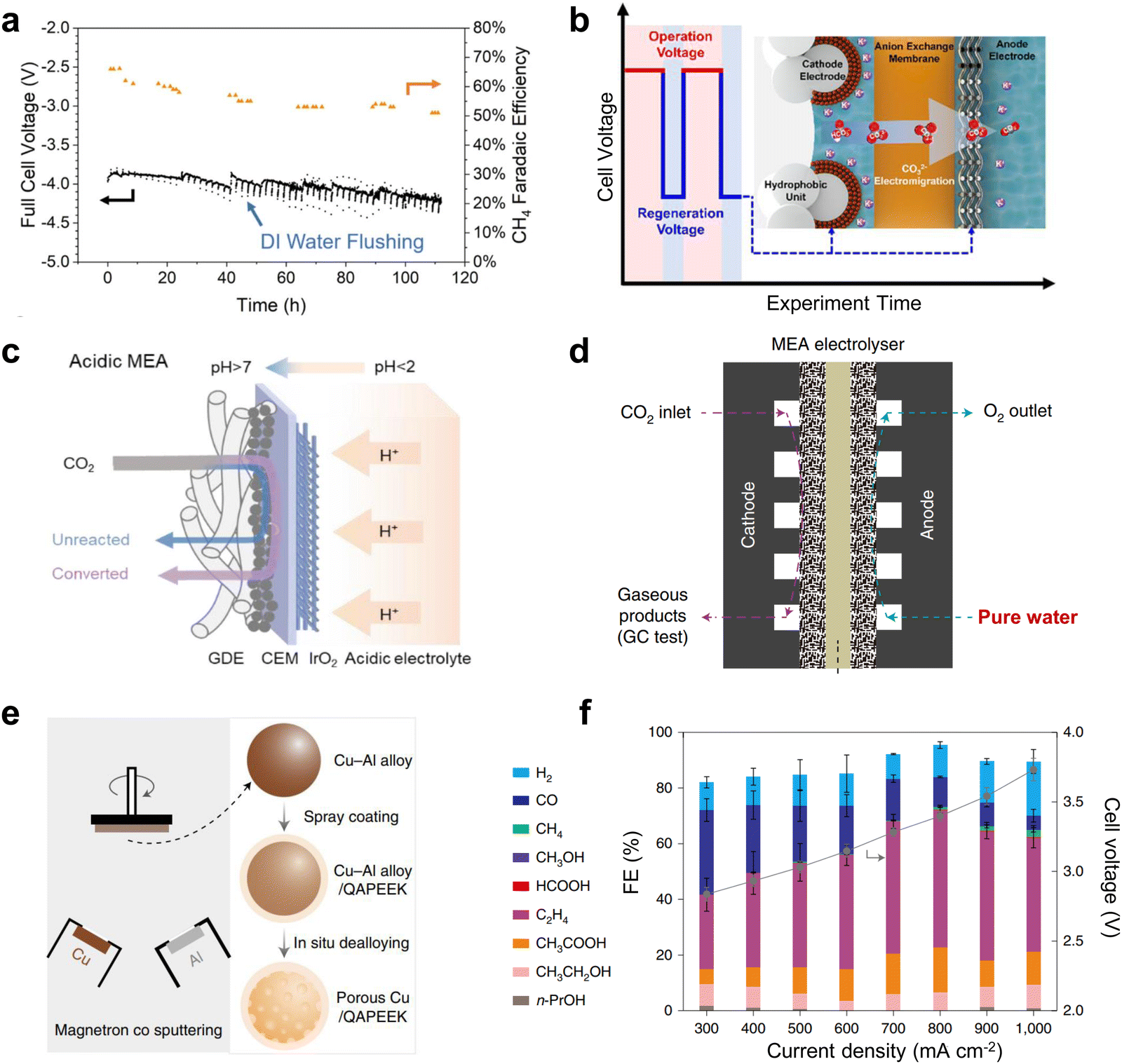 | ||
| Fig. 8 Solutions to the cathodic carbonate precipitation problem. (a) Regular flushing of the GDE to achieve stability for up to 100 h. Reproduced with permission from ref. 65 copyright 2021, Springer Nature. (b) Under an alternating electric field, the carbonate is transferred to the anode by electromigration at low potential. Reproduced with permission from ref. 66 copyright 2021, American Chemical Society. (c) Carbonate regeneration processes in acidic electrolytes. Reproduced with permission from ref. 67 copyright 2022, American Chemical Society. (d) Structural illustration of the MEA with pure water. (e) Schematic illustration of the preparation process of the porous Cu-QAPEEK GDE. (f) Product selectivity and cell voltage at different current densities. Reproduced with permission from ref. 68 copyright 2022, Springer Nature. | ||
4.2 Ion exchange membrane
As an important component of MEA electrolyzers, the ion exchange membrane plays a vital role in controlling ion transport, regulating pH, and avoiding crossover of cathode and anode products. There are three main types of ion exchange membranes used for the CO2RR depending on the ion transfer: anion exchange membranes (AEM), cation exchange membranes (CEM) and bipolar membranes (BPM).Firstly, AEMs (Fig. 9a) can transfer anions (such as OH−, CO32−, etc.) produced by the cathode to the anode, avoiding the transmembrane transfer of H+ produced by the anode, thus inhibiting the HER reaction and improving the CO2 reduction selectivity. However, since the CO32− produced at the cathode will transport across the membrane to the anode to produce CO2 with H+, AEMs will lead to a large amount of carbon loss, and the theoretical CO2 utilization rate will not exceed 50%.73 CEMs (Fig. 9b) can transfer H+ from the anode to cathode, and then generate CO2 with CO32− produced at the cathode, so that the CO2 can be reused and carbon loss can be avoided. However, due to the transfer of H+ to the cathode, this tends to cause serious HER side reactions. Finally, BPMs (Fig. 9c) consist of a CEM and an AEM with an H2O layer between the two membranes, providing H+ and OH− to the cathode and anode through the water dissociation catalyst. BPM can avoid the carbon loss from the cathode while avoiding the HER caused by high H+ at the cathode.74 Unfortunately, there are some problems with the BPM, such as high cost, poor durability, etc. and the membrane will crack from the middle during long duration use.
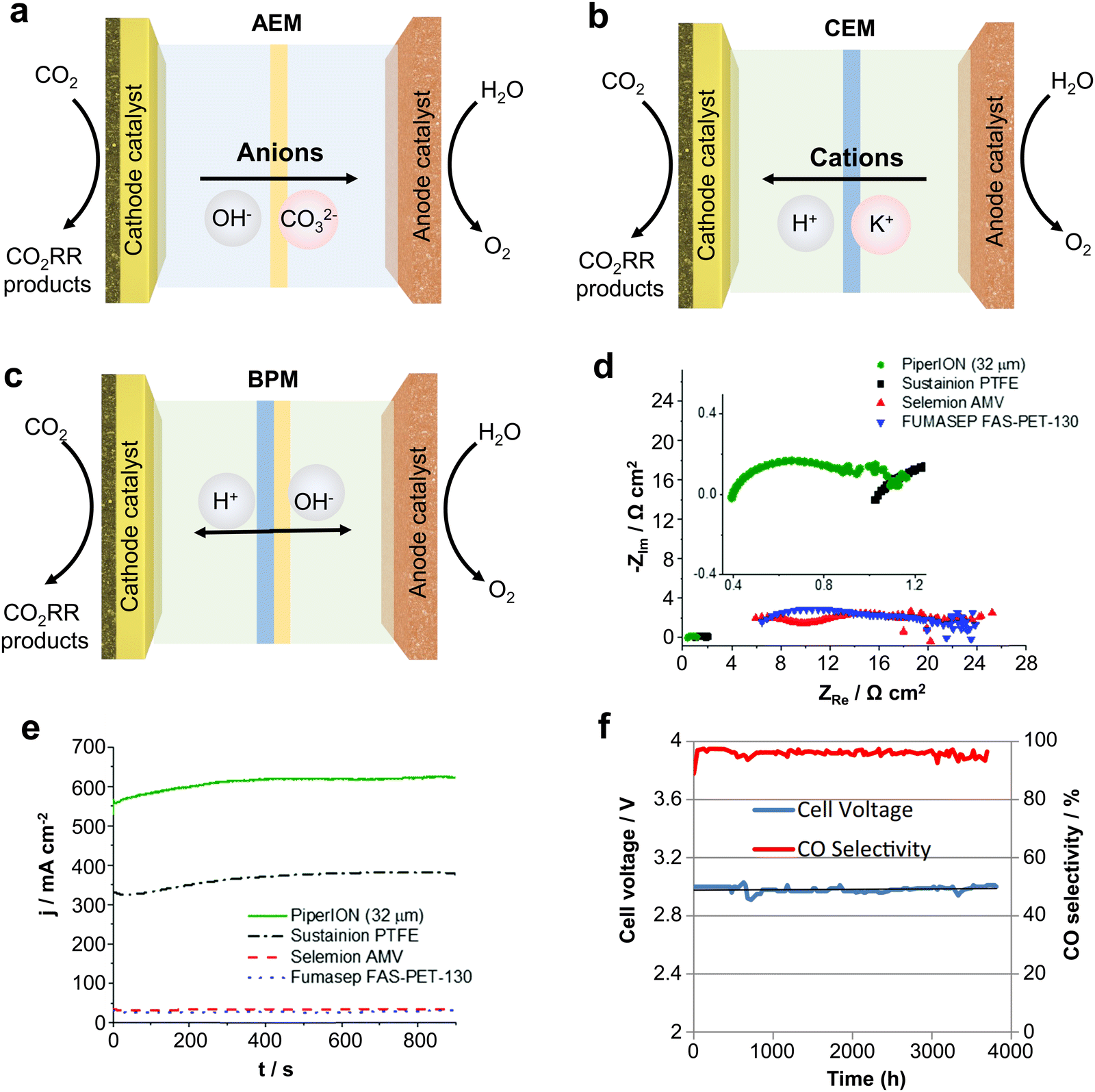 | ||
| Fig. 9 Types of IEMs and their effects on CO2 electrolysis performance. Different types of ion exchange membranes: (a) AEM, (b) CEM and (c) BPM. (d) Impedance and (e) current density of different AEMs at the same voltage. (f) Imidazolium-based ion-functionalized AEM achieves over 3000 hours of CO2 electrolysis. Rational design of ion exchange membranes can improve the ion conduction speed, current density and stability. (d) and (e) Reproduced with permission from ref. 56 copyright 2020, RSC Publishing. (f) Reproduced with permission from ref. 77 copyright 2018, ECS Publishing. | ||
Therefore, subtle modifications of ion exchange membranes are also necessary if scalable electrolyzers are to meet the requirements of industrialization. In this regard, problems such as carbon loss in AEM, severe cathode HERs in the CEM and poor durability of the BPM, still remain big challenges. To solve these problems, Sinton et al.75 designed a microchannel solid electrolyte to enable the capture and recovery of CO32− before it reaches the anode and reduce CO2 loss to ∼3% whilst using an AEM. Ma et al.76 constructed a hydrophobic environment by depositing a porous carbon layer on Fe nanoparticles to inhibit the penetration of water in a strongly acidic electrolyte whilst using a CEM, achieving a CO selectivity close to 90%.
In addition, some physicochemical properties of ion exchange membranes (IEMs) can have a dramatic impact on the performance of the electrolyzer. For example, IEMs with lower impedance have higher ionic conductivity and give the electrolyzers a higher circuit density (Fig. 9d and e).56 Meanwhile, IEMs are made more durable by characteristic functional group modifications. Masel et al.77 achieved 3000 hours of operation at a current density of 200 mA cm−2 by functionalizing an AEM with imidazole-based ionic liquid using Ag as the catalyst (Fig. 9f). Therefore, it is crucial to design IEMs with higher ionic conductivity and more durability. Overall, the improvement and design based on ion-exchange membranes is an important strategy to accelerate the industrialization of scalable CO2 electrolyzers.
4.3 Flow channel design
The flow plate is a critical component that ensures proper water/CO2 management and stabilizes the system reaction state parameters. The structural parameters of the electrolyzer flow channel have an impact on the local pressure, flow rate, and uniformity of distribution of the fluid. The state of these fluids is closely related to the current density and stability of CO2 reduction. Therefore, it is possible to improve the flow state of the fluid by adjusting the distribution structure, depth, and width of the flow channel, thus improving the performance of the CO2 electrolyzer.To date, little research has been done in the field of electrochemical CO2 reduction for the simulation and design of flow channels, drawing mainly from studies in fuel cells and redox flow batteries. Flow field designs typically include parallel, serpentine and interdigitated flow fields.78 Appropriate designs, such as spiral, circular, and mesh flow fields, would optimize the geometric structure of the original flow field to improve distribution uniformity and enhance mass transfer.79,80 Additionally, biomimetic structures like the lung-inspired flow field, which is inspired by the fractal geometry of the lungs, has emerged to overcome the issue of uniform reactant distribution.81 Typical CO2 electrolyzer flow fields are now mainly serpentine and spiral flow paths. Yan et al.82 reported that the mass fraction distribution of gas was positively correlated with the current density. In the serpentine flow channel (Fig. 10a), the turns have more resistance, leading to a greater local concentration of CO2 than in the linear flow channel. In the electrocatalytic process, this aspect of mass transfer will be easier, which will lead to inhomogeneous current density and thus instability of the reaction (local salt precipitation, GDL local decomposition damage, etc.). In the spiral flow channel (Fig. 10b), there is almost no turnaround, avoiding such problems. The use of a spiral flow channel results in a flow channel with a long total length, increasing the CO2 residence time and the CO2 single conversion rate.83,84 However, at lower CO2 flow rates, this also increases the difference in CO2 concentration between the inlet and outlet, resulting in uneven current density distribution and additional energy loss. Computational fluid dynamics simulation is an essential tool to assist in the rational design of flow channel structures and understand the impact of geometric parameters on electrolysis performance. Berlinguette et al. developed a 3D flow plate model for CO2 reduction (Fig. 10c), and found that increasing the CO2 humidity at the inlet can make water distribution more uniform.85 In general, ensuring the uniformity of CO2 gas transport, reducing the pressure drop, and increasing the CO2 conversion rate are the keys to the design of flow paths in the current dischargeable large CO2 electrolyzer.
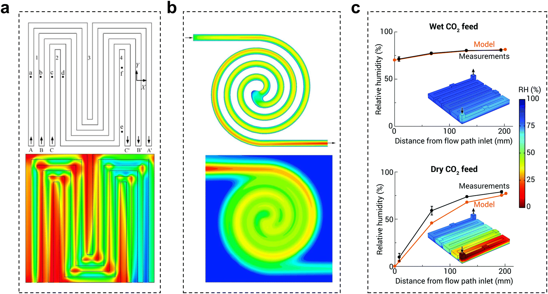 | ||
| Fig. 10 Effect of the flow channel on CO2 electrolysis. Schematic diagram of the gas mass distribution in (a) a serpentine flow channel and (b) a spiral flow channel, red to blue indicates a change from a high mass concentration to a low mass concentration. (c) Comparison of relative humidity (RH) in the cathode flow field obtained with the analytical electrolyzer and model for wet and dry CO2 feeds. (a) Reproduced with permission from ref. 82 copyright 2007, Elsevier Publishing Group. (b) Reproduced with permission from ref. 83 copyright 2017, Wiley. (c) Reproduced with permission from ref. 85 copyright 2020, RSC Publishing. | ||
4.4 Reduced product separation costs
The cost of product separation is also an important part of large-scale CO2 electrolysis costs. Currently, there have been advances in research to effectively reduce the cost of CO2RR products through the design of electrolyzers. Next, we discuss the impact of electrolysis parameters on separation costs.For the current separation of the products of CO2 electrolysis, there are two aspects to consider: the separation of the products in the gas phase and in the liquid phase. For the separation of gas-phase products, industry currently uses, in the main, pressure swing adsorption (PSA) technology. The principle is to use a molecular sieve based on the gas molecule adsorption performance differences of different gas molecules and separate the gas mixture.86 The cost of separation is closely related to factors such as the type and content of the gas. Jiao et al.87 reported that the cost of separating the gas product (a mixture of CO2 and CO) using PSA technology is about 23% of the total operating cost at 10% CO2 single-pass conversion efficiency in the CO2RR to CO process. In contrast, increasing the CO2 single-pass conversion efficiency to 50% reduces the separation cost by 78% (6% of the total cost). Therefore, the key to reducing the cost of gas product separation is therefore to increase the CO2 single-pass conversion efficiency, i.e., to increase the concentration of the product in the effluent gas.
For the separation of liquid phase products, distillation is often used in industry to separate substances by utilizing their different boiling points, but this process is extremely energy intensive.88 Recently Wang et al.70 have separated relatively pure products such as HCOOH by using solid electrolyte membrane electrodes, which is an inexpensive method to separate the products in situ, and is expected to be used in later developments.
5. Summary and outlook
Electrochemical CO2 conversion is a promising approach to carbon utilization and has great potential to reduce the atmospheric CO2 concentration and realize economic benefits by obtaining value-added commodities. The development of large-scale CO2 electrolyzers with excellent performance is the key to achieving industrial-scale conversion of CO2. This perspective mainly outlines several typical electrolyzers for CO2 electrochemical conversion and highlights the most promising role of MEA-type electrolyzers for industrial applications. Currently, numerous researchers have undertaken investigations on large-area electrolyzers, power stacks, and high-pressure/heated electrolyzers as part of the initial exploratory efforts towards scalable CO2 electrolysis. These amplifiable devices have shown outstanding performance in increasing CO2 conversion rates and reducing costs. However, there are still some issues that cannot be ignored, such as how to avoid severe salt precipitation, excessive energy consumption, short durability, and the high base unit cost.To achieve industrialization of CO2RR technologies, the design of scalable electrolyzers needs to be optimized in terms of device structure, flow channels and ion exchange membranes. The following is a summary of these aspects.
(1) Multi-field coupling of temperature, pressure, flow field and atmosphere. Optimizing the temperature can decrease the impedance of the electrolyzers and enhance the ion conduction rate in the electrolyte, leading to an increased reaction current density. Applying pressure can elevate the local CO2 concentration on the catalyst surface, which is conducive to the CO2 mass transfer process, and ultimately, increases the current density and selectivity. The flow field parameters are closely related to the local pressure, flow rate and atmosphere homogeneity of the fluid, which will affect the current density and stability of the CO2RR. Adjusting the composition of the cathode atmosphere (CO2 + CO/O2 co-feed or flue gas) can enhance the selectivity of specific products and reduce the feed cost. Taking these operational parameters together and optimizing the factors required for CO2 electrolysis should be comprehensively explored to maximize the CO2RR performance.
(2) Robust IEMs for optimal MEA configurations. IEMs with high ionic conductivity which prevent the crossover of cathode and anode products can achieve long-term stability, high energy efficiency, and high yields. In particular, targeted functional group modifications of IEMs have been shown to enhance their ionic conductivity, resulting in elevated current densities during the reaction. Furthermore, IEMs possessing superior mechanical strength promote prolonged operation in scalable electrolyzers, thus reducing reaction expenses.
(3) Avoiding salt precipitation around the cathode. To maintain the stability of the CO2RR electrolyzer, it is necessary to carry away or convert the carbonate produced, by changing the inflow of CO2 gas to the cathode (e.g., forced passage of a CO2 saturated electrolyte) or by using CEM electrolysis in an acidic electrolyte. Pure water-fed CO2 electrolysis also effectively avoids the formation of carbonates while yielding a pure liquid phase product.
(4) Non-precious CO2RR and OER electrocatalysts. In a full-cell system, the CO2RR cathode material assumes a pivotal function in enhancing product selectivity and ensuring sustained reaction stability over time. Large-scale fabrication of non-precious, highly selective CO2RR electrocatalysts is still challenging. In addition, OER anode materials in the MEA system also play an important role in reducing the voltage and reducing the total energy input, which should ensure that the anode material does not poison the cathode catalyst through the IEM. However, Ir-based anode materials with high loadings currently still dominant the MEA configurations.
In summary, we believe that with continued research and development of scalable CO2 electrolyzers, CO2 electrolysis technology will be effectively implemented in industrial production in the near future.
Conflicts of interest
There are no conflicts to declare.Acknowledgements
This work was financially supported by the Australian Research Council Discovery Project (DP200100965) and the Science and Technology Commission of Shanghai Municipality (21DZ1207101, 22ZR1416400).References
- D. Wakerley, S. Lamaison, J. Wicks, A. Clemens, J. Feaster, D. Corral, S. A. Jaffer, A. Sarkar, M. Fontecave, E. B. Duoss, S. Baker, E. H. Sargent, T. F. Jaramillo and C. Hahn, Nat. Energy, 2022, 7, 130–143 CrossRef CAS.
- S. Jin, Z. Hao, K. Zhang, Z. Yan and J. Chen, Angew. Chem., Int. Ed., 2021, 60, 20627–20648 CrossRef CAS PubMed.
- A. Rode, T. Carleton, M. Delgado, M. Greenstone, T. Houser, S. Hsiang, A. Hultgren, A. Jina, R. E. Kopp, K. E. McCusker, I. Nath, J. Rising and J. Yuan, Nature, 2021, 598, 308–314 CrossRef CAS PubMed.
- Y. Yan, T. N. Borhani, S. G. Subraveti, K. N. Pai, V. Prasad, A. Rajendran, P. Nkulikiyinka, J. O. Asibor, Z. Zhang, D. Shao, L. Wang, W. Zhang, Y. Yan, W. Ampomah, J. You, M. Wang, E. J. Anthony, V. Manovic and P. T. Clough, Energy Environ. Sci., 2021, 14, 6122–6157 RSC.
- R. Meys, A. Kätelhön, M. Bachmann, B. Winter, C. Zibunas, S. Suh and A. Bardow, Science, 2021, 374, 71–76 CrossRef CAS PubMed.
- P.-F. Sui, M. Gao, M. Zhu, C. Xu, Y.-C. Wang, S. Liu and J.-L. Luo, EES Catal., 2023, 1, 290–300 RSC.
- Q. Zhou, X. Tang, S. Qiu, L. Wang, L. Hao and Y. Yu, Mater. Today Phys., 2023, 33, 101050 CrossRef CAS.
- K. Jiang and P. Ashworth, Renewable Sustainable Energy Rev., 2021, 138, 110521 CrossRef CAS.
- J. Mertens, C. Breyer, K. Arning, A. Bardow, R. Belmans, A. Dibenedetto, S. Erkman, J. Gripekoven, G. Léonard, S. Nizou, D. Pant, A. S. Reis-Machado, P. Styring, J. Vente, M. Webber and C. J. Sapart, Joule, 2023, 7, 442–449 CrossRef.
- L. Sun and W. Chen, J. Cleaner Prod., 2022, 333, 130027 CrossRef CAS.
- J. G. Vitillo, Chem. Rev., 2017, 117, 9521–9523 CrossRef CAS PubMed.
- H. Shin, K. U. Hansen and F. Jiao, Nat. Sustain., 2021, 4, 911–919 CrossRef.
- W. Gao, S. Liang, R. Wang, Q. Jiang, Y. Zhang, Q. Zheng, B. Xie, C. Y. Toe, X. Zhu, J. Wang, L. Huang, Y. Gao, Z. Wang, C. Jo, Q. Wang, L. Wang, Y. Liu, B. Louis, J. Scott, A.-C. Roger, R. Amal, H. He and S.-E. Park, Chem. Soc. Rev., 2020, 49, 8584–8686 RSC.
- S. M. Jordaan and C. Wang, Nat. Catal., 2021, 4, 915–920 CrossRef.
- S. Sarkar, J. Raj, D. Bagchi, A. Cherevotan, C. P. Vinod and S. C. Peter, EES Catal., 2023, 1, 162–170 RSC.
- W. Zhang, C. Huang, Q. Xiao, L. Yu, L. Shuai, P. An, J. Zhang, M. Qiu, Z. Ren and Y. Yu, J. Am. Chem. Soc., 2020, 142, 11417–11427 CrossRef CAS PubMed.
- F.-Y. Gao, R.-C. Bao, M.-R. Gao and S.-H. Yu, J. Mater. Chem. A, 2020, 8, 15458–15478 RSC.
- W. Zhang, C. Huang, J. Zhu, Q. Zhou, R. Yu, Y. Wang, P. An, J. Zhang, M. Qiu, L. Zhou, L. Mai, Z. Yi and Y. Yu, Angew. Chem., Int. Ed., 2022, 61, e202112116 CrossRef CAS PubMed.
- W. Ma, X. He, W. Wang, S. Xie, Q. Zhang and Y. Wang, Chem. Soc. Rev., 2021, 50, 12897–12914 RSC.
- C. Chen, J. F. Khosrowabadi Kotyk and S. W. Sheehan, Chem, 2018, 4, 2571–2586 CAS.
- M. Zheng, P. Wang, X. Zhi, K. Yang, Y. Jiao, J. Duan, Y. Zheng and S.-Z. Qiao, J. Am. Chem. Soc., 2022, 144, 14936–14944 CrossRef CAS PubMed.
- X. Chen, J. Chen, N. M. Alghoraibi, D. A. Henckel, R. Zhang, U. O. Nwabara, K. E. Madsen, P. J. A. Kenis, S. C. Zimmerman and A. A. Gewirth, Nat. Catal., 2021, 4, 20–27 CrossRef CAS.
- J. E. Huang, F. Li, A. Ozden, A. Sedighian Rasouli, F. P. García de Arquer, S. Liu, S. Zhang, M. Luo, X. Wang, Y. Lum, Y. Xu, K. Bertens, R. K. Miao, C.-T. Dinh, D. Sinton and E. H. Sargent, Science, 2021, 372, 1074–1078 CrossRef CAS PubMed.
- R. B. Kutz, Q. Chen, H. Yang, S. D. Sajjad, Z. Liu and I. R. Masel, Energy Technol., 2017, 5, 929–936 CrossRef CAS.
- B. Pan, Y. Wang and Y. Li, Chem. Catal., 2022, 2, 1267–1276 CrossRef CAS.
- E. W. Lees, B. A. W. Mowbray, F. G. L. Parlane and C. P. Berlinguette, Nat. Rev. Mater., 2022, 7, 55–64 CrossRef CAS.
- H. Yang, L. Shang, Q. Zhang, R. Shi, G. I. N. Waterhouse, L. Gu and T. Zhang, Nat. Commun., 2019, 10, 4585 CrossRef PubMed.
- W. Ni, Z. Liu, Y. Zhang, C. Ma, H. Deng, S. Zhang and S. Wang, Adv. Mater., 2021, 33, 2003238 CrossRef CAS PubMed.
- H. Q. Fu, J. Liu, N. M. Bedford, Y. Wang, J. W. Sun, Y. Zou, M. Dong, J. Wright, H. Diao, P. Liu, H. G. Yang and H. Zhao, Adv. Mater., 2022, 34, 2202854 CrossRef CAS PubMed.
- J. Y. Zhao, Y. Liu, W. Li, C. F. Wen, H. Q. Fu, H. Y. Yuan, P. F. Liu and H. G. Yang, Chem. Catal., 2023, 3, 100471 CrossRef CAS.
- C. Liu, Y. Wu, K. Sun, J. Fang, A. Huang, Y. Pan, W.-C. Cheong, Z. Zhuang, Z. Zhuang, Q. Yuan, H. L. Xin, C. Zhang, J. Zhang, H. Xiao, C. Chen and Y. Li, Chem, 2021, 7, 1297–1307 CAS.
- H. Q. Fu, J. Liu, N. M. Bedford, Y. Wang, J. Wright, P. F. Liu, C. F. Wen, L. Wang, H. Yin, D. Qi, P. Liu, H. G. Yang and H. Zhao, Nano-Micro Lett., 2022, 14, 121 CrossRef CAS PubMed.
- D. Yao, C. Tang, X. Zhi, B. Johannessen, A. Slattery, S. Chern and S.-Z. Qiao, Adv. Mater., 2023, 85, 2209386 CrossRef PubMed.
- D. Yao, C. Tang, A. Vasileff, X. Zhi, Y. Jiao and S. Z. Qiao, Angew. Chem., Int. Ed., 2021, 60, 18178–18184 CrossRef CAS PubMed.
- S. Ren, D. Joulié, D. Salvatore, K. Torbensen, M. Wang, M. Robert and C. P. Berlinguette, Science, 2019, 365, 367–369 CrossRef CAS PubMed.
- A. Inoue, T. Harada, S. Nakanishi and K. Kamiya, EES Catal., 2023, 1, 9–16 RSC.
- X. Zhang, Y. Wang, M. Gu, M. Wang, Z. Zhang, W. Pan, Z. Jiang, H. Zheng, M. Lucero, H. Wang, G. E. Sterbinsky, Q. Ma, Y.-G. Wang, Z. Feng, J. Li, H. Dai and Y. Liang, Nat. Energy, 2020, 5, 684–692 CrossRef CAS.
- L. Ge, H. Rabiee, M. Li, S. Subramanian, Y. Zheng, J. H. Lee, T. Burdyny and H. Wang, Chem, 2022, 8, 663–692 CAS.
- Y. Cheng, P. Hou, X. Wang and P. Kang, Acc. Chem. Res., 2022, 55, 231–240 CrossRef CAS PubMed.
- B. Endrődi, A. Samu, E. Kecsenovity, T. Halmágyi, D. Sebők and C. Janáky, Nat. Energy, 2021, 6, 439–448 CrossRef PubMed.
- J. Gao, H. Zhang, X. Guo, J. Luo, S. M. Zakeeruddin, D. Ren and M. Grätzel, J. Am. Chem. Soc., 2019, 141, 18704–18714 CrossRef CAS PubMed.
- M. Zhong, K. Tran, Y. Min, C. Wang, Z. Wang, C.-T. Dinh, P. De Luna, Z. Yu, A. S. Rasouli, P. Brodersen, S. Sun, O. Voznyy, C.-S. Tan, M. Askerka, F. Che, M. Liu, A. Seifitokaldani, Y. Pang, S.-C. Lo, A. Ip, Z. Ulissi and E. H. Sargent, Nature, 2020, 581, 178–183 CrossRef CAS PubMed.
- Z. Yin, H. Peng, X. Wei, H. Zhou, J. Gong, M. Huai, L. Xiao, G. Wang, J. Lu and L. Zhuang, Energy Environ. Sci., 2019, 12, 2455–2462 RSC.
- N. M. Haegel, R. Margolis, T. Buonassisi, D. Feldman, A. Froitzheim, R. Garabedian, M. Green, S. Glunz, H.-M. Henning, B. Holder, I. Kaizuka, B. Kroposki, K. Matsubara, S. Niki, K. Sakurai, R. A. Schindler, W. Tumas, E. R. Weber, G. Wilson, M. Woodhouse and S. Kurtz, Science, 2017, 356, 141–143 CAS.
- J. Wei Sun, X. Wu, P. Fei Liu, J. Chen, Y. Liu, Z. Xin Lou, J. Yue Zhao, H. Yang Yuan, A. Chen, X. Lu Wang, M. Zhu, S. Dai and H. Gui Yang, Nat. Commun., 2023, 14, 1599 Search PubMed.
- T. Zheng, K. Jiang, N. Ta, Y. Hu, J. Zeng, J. Liu and H. Wang, Joule, 2019, 3, 265–278 CAS.
- B. Endrodi, E. Kecsenovity, A. A. Samu, T. Halmágyi, S. Rojas-Carbonell, L. Wang, Y. Yan and C. Janáky, Energy Environ. Sci., 2020, 13, 4098–4105 RSC.
- B. Wu, B. Tan, G. Tan, M. Zeng, J. Luo, G. Hu, J. Luo, Z. Hao, S. Lai and B. Liu, RSC Adv., 2021, 11, 39153–39168 CAS.
- B. Endrődi, E. Kecsenovity, A. Samu, F. Darvas, R. V. Jones, V. Török, A. Danyi and C. Janáky, ACS Energy Lett., 2019, 4, 1770–1777 Search PubMed.
- W. H. Lee, C. Lim, S. Y. Lee, K. H. Chae, C. H. Choi, U. Lee, B. K. Min, Y. J. Hwang and H.-S. Oh, Nano Energy, 2021, 84, 105859 CrossRef CAS.
- P. Wei, D. Gao, T. Liu, H. Li, J. Sang, C. Wang, R. Cai, G. Wang and X. Bao, Nat. Nanotechnol., 2023, 18, 299–306 CrossRef CAS PubMed.
- N. Kato, S. Mizuno, M. Shiozawa, N. Nojiri, Y. Kawai, K. Fukumoto, T. Morikawa and Y. Takeda, Joule, 2021, 5, 687–705 CrossRef CAS.
- G. Wen, B. Ren, X. Wang, D. Luo, H. Dou, Y. Zheng, R. Gao, J. Gostick, A. Yu and Z. Chen, Nat. Energy, 2022, 7, 978–988 CAS.
- C. Xia, Y. Qiu, Y. Xia, P. Zhu, G. King, X. Zhang, Z. Wu, J. Y. Kim, D. A. Cullen, D. Zheng, P. Li, M. Shakouri, E. Heredia, P. Cui, H. N. Alshareef, Y. Hu and H. Wang, Nat. Chem., 2021, 13, 887–894 CAS.
- P. Wei, H. Li, R. Li, Y. Wang, T. Liu, R. Cai, D. Gao, G. Wang and X. Bao, Small, 2023, 2300856 CrossRef CAS PubMed.
- B. Endrődi, E. Kecsenovity, A. Samu, T. Halmágyi, S. Rojas-Carbonell, L. Wang, Y. Yan and C. Janáky, Energy Environ. Sci., 2020, 13, 4098–4105 RSC.
- J. P. Edwards, Y. Xu, C. M. Gabardo, C.-T. Dinh, J. Li, Z. Qi, A. Ozden, E. H. Sargent and D. Sinton, Appl. Energy, 2020, 261, 114305 CAS.
- Y. Xu, J. P. Edwards, J. Zhong, C. P. O’Brien, C. M. Gabardo, C. McCallum, J. Li, C.-T. Dinh, E. H. Sargent and D. Sinton, Energy Environ. Sci., 2020, 13, 554–561 RSC.
- X. Wang, J. F. de Araújo, W. Ju, A. Bagger, H. Schmies, S. Kühl, J. Rossmeisl and P. Strasser, Nat. Nanotechnol., 2019, 14, 1063–1070 CrossRef CAS PubMed.
- M. He, C. Li, H. Zhang, X. Chang, J. G. Chen, W. A. Goddard, M.-J. Cheng, B. Xu and Q. Lu, Nat. Commun., 2020, 11, 3844 CrossRef CAS PubMed.
- D. Kim, W. Choi, H. W. Lee, S. Y. Lee, Y. Choi, D. K. Lee, W. Kim, J. Na, U. Lee, Y. J. Hwang and D. H. Won, ACS Energy Lett., 2021, 6, 3488–3495 CrossRef CAS.
- X. Lu, Z. Jiang, X. Yuan, Y. Wu, R. Malpass-Evans, Y. Zhong, Y. Liang, N. B. McKeown and H. Wang, Sci. Bull., 2019, 64, 1890–1895 CrossRef CAS PubMed.
- Y. Takeda, S. Mizuno, R. Iwata, T. Morikawa and N. Kato, J. CO2 Util., 2023, 71, 102472 CrossRef CAS.
- P. Li, X. Lu, Z. Wu, Y. Wu, R. Malpass-Evans, N. B. McKeown, X. Sun and H. Wang, Angew. Chem., Int. Ed., 2020, 59, 10918–10923 CrossRef CAS PubMed.
- Y. Xu, F. Li, A. Xu, J. P. Edwards, S.-F. Hung, C. M. Gabardo, C. P. O’Brien, S. Liu, X. Wang, Y. Li, J. Wicks, R. K. Miao, Y. Liu, J. Li, J. E. Huang, J. Abed, Y. Wang, E. H. Sargent and D. Sinton, Nat. Commun., 2021, 12, 2932 CrossRef CAS PubMed.
- Y. Xu, J. P. Edwards, S. Liu, R. K. Miao, J. E. Huang, C. M. Gabardo, C. P. O’Brien, J. Li, E. H. Sargent and D. Sinton, ACS Energy Lett., 2021, 6, 809–815 CrossRef CAS.
- B. Pan, J. Fan, J. Zhang, Y. Luo, C. Shen, C. Wang, Y. Wang and Y. Li, ACS Energy Lett., 2022, 7, 4224–4231 CrossRef CAS.
- W. Li, Z. Yin, Z. Gao, G. Wang, Z. Li, F. Wei, X. Wei, H. Peng, X. Hu, L. Xiao, J. Lu and L. Zhuang, Nat. Energy, 2022, 7, 835–843 CrossRef CAS.
- T. Li, E. W. Lees, M. Goldman, D. A. Salvatore, D. M. Weekes and C. P. Berlinguette, Joule, 2019, 3, 1487–1497 CrossRef CAS.
- C. Xia, P. Zhu, Q. Jiang, Y. Pan, W. Liang, E. Stavitski, H. N. Alshareef and H. Wang, Nat. Energy, 2019, 4, 776–785 CrossRef CAS.
- K. M. G. Langie, K. Tak, C. Kim, H. W. Lee, K. Park, D. Kim, W. Jung, C. W. Lee, H.-S. Oh, D. K. Lee, J. H. Koh, B. K. Min, D. H. Won and U. Lee, Nat. Commun., 2022, 13, 7482 CrossRef CAS PubMed.
- G. Lee, Y. C. Li, J.-Y. Kim, T. Peng, D.-H. Nam, A. Sedighian Rasouli, F. Li, M. Luo, A. H. Ip, Y.-C. Joo and E. H. Sargent, Nat. Energy, 2021, 6, 46–53 CrossRef CAS.
- J. Y. T. Kim, P. Zhu, F.-Y. Chen, Z.-Y. Wu, D. A. Cullen and H. Wang, Nat. Catal., 2022, 5, 288–299 CrossRef CAS.
- K. Xie, R. K. Miao, A. Ozden, S. Liu, Z. Chen, C.-T. Dinh, J. E. Huang, Q. Xu, C. M. Gabardo, G. Lee, J. P. Edwards, C. P. O’Brien, S. W. Boettcher, D. Sinton and E. H. Sargent, Nat. Commun., 2022, 13, 3609 CrossRef CAS PubMed.
- Y. Xu, R. K. Miao, J. P. Edwards, S. Liu, C. P. O’Brien, C. M. Gabardo, M. Fan, J. E. Huang, A. Robb, E. H. Sargent and D. Sinton, Joule, 2022, 6, 1333–1343 CrossRef CAS.
- Q. Fan, G. Bao, X. Chen, Y. Meng, S. Zhang and X. Ma, ACS Catal., 2022, 12, 7517–7523 CrossRef CAS.
- Z. Liu, H. Yang, R. Kutz and R. I. Masel, J. Electrochem. Soc., 2018, 165, J3371 CrossRef CAS.
- A. Kazim, H. T. Liu and P. Forges, J. Appl. Electrochem., 1999, 29, 1409–1416 CrossRef CAS.
- Y. Vazifeshenas, K. Sedighi and M. Shakeri, Int. J. Hydrogen Energy, 2015, 40, 15032–15039 CrossRef CAS.
- S. Rau, S. Vierrath, J. Ohlmann, A. Fallisch, D. Lackner, F. Dimroth and T. Smolinka, Energy Technol., 2014, 2, 43–53 CrossRef CAS.
- P. Trogadas, J. I. S. Cho, T. P. Neville, J. Marquis, B. Wu, D. J. L. Brett and M. O. Coppens, Energy Environ. Sci., 2018, 11, 136–143 RSC.
- X.-D. Wang, Y.-Y. Duan and W.-M. Yan, J. Power Sources, 2007, 173, 210–221 CrossRef CAS.
- B. Ibrahimoglu, M. Z. Yilmazoglu and S. Celenk, Fuel Cells, 2017, 17, 786–793 CAS.
- R. Kas, A. G. Star, K. Yang, T. Van Cleve, K. C. Neyerlin and W. A. Smith, ACS Sustainable Chem. Eng., 2021, 9, 1286–1296 CAS.
- D. G. Wheeler, B. A. W. Mowbray, A. Reyes, F. Habibzadeh, J. He and C. P. Berlinguette, Energy Environ. Sci., 2020, 13, 5126–5134 RSC.
- P. Hao, Y. Shi, S. Li and N. Cai, Adsorption, 2020, 26, 1093–1100 CAS.
- E. Jeng and F. Jiao, React. Chem. Eng., 2020, 5, 1768–1775 RSC.
- L. Tang, Nat. Methods, 2019, 16, 18 CrossRef CAS PubMed.
| This journal is © The Royal Society of Chemistry 2023 |