 Open Access Article
Single-site catalysts for CO2 electroreduction
Wenzhong
Huang†
a,
Jiexin
Zhu†
 a,
Shanlin
Liu†
a,
Wei
Zhang
a,
Liang
Zhou
a,
Shanlin
Liu†
a,
Wei
Zhang
a,
Liang
Zhou
 *abc and
Liqiang
Mai
 *abc
*abc
aState Key Laboratory of Advanced Technology for Materials Synthesis and Processing, Wuhan University of Technology, Wuhan 430070, Hubei, P. R. China. E-mail: mlq518@whut.edu.cn; liangzhou@whut.edu.cn
bHubei Longzhong Laboratory, Wuhan University of Technology (Xiangyang Demonstration Zone), Xiangyang 441000, Hubei, P. R. China
cHainan Institute, Wuhan University of Technology, Sanya 572000, Hainan, P. R. China
First published on 22nd May 2023
Abstract
The use of electrocatalytic carbon dioxide reduction (ECR) for producing various high-value-added products is critical for achieving carbon neutrality. In the past decades, single-site catalysts (SSCs), such as single-atom catalysts, homogeneous molecular catalysts, metal–organic-framework-supported and covalent-organic-framework-supported SSCs, have shown good selectivity and activity for ECR. In this review, we systematically discuss the design principles and optimization strategies for ECR SSCs, starting with the reaction mechanism and descriptors of ECR. We highlight representative studies conducted in the past decades to elucidate the selectivity and reaction mechanisms of different types of SCCs for ECR. Finally, we describe the remaining challenges and perspectives in the application of these emerging catalysts.
Broader contextExcessive fuel combustion and greenhouse gas emission lead to global environmental deterioration. By converting carbon dioxide into valued chemicals and fuels, electrocatalytic carbon dioxide reduction (ECR) is of great significance to alleviate the environmental issue. However, ECR electrocatalysts suffer from limited activity, low selectivity, and unsatisfactory stability. As a result, developing efficient, stable, and low-cost ECR catalysts is of vital importance. Recently, single-site catalysts (SSCs) have emerged as promising ECR catalysts due to their precisely controllable structure and high atomic utilization efficiency. Herein, to accelerate the development of SSCs for ECR, it is necessary to summarize their recent progress on design principles and optimization strategies. This review shows how SSCs are one of most promising candidates for ECR based on latest studies. The researches on these emerging SSCs for ECR have also been comprehensively summarized and discussed, including their catalytic mechanisms, synthesis, optimization strategies, remaining challenges and perspectives. We hope to provide a comprehensive overview of state-of-art progress to readers and shed light on this important field. |
1. Introduction
Because of industrial development and the progress of society, a large amount of carbon dioxide (CO2) is emitted into the air, causing the greenhouse effect. Therefore, the recovery of CO2 is important for mitigating the current crisis. In particular, electrocatalytic carbon dioxide reduction (ECR) produces C1, C2, and C2+ products (such as carbon monoxide, ethanol, and dimethyl carbonate) with industrial value and promotes the carbon cycle of the natural environment.1–4 However, the high-energy barrier to activate the stable CO2 molecules makes ECR full of challenges.5–7 In addition, the large-scale application of ECR often suffers from limitations such as limited activity, low selectivity, and unsatisfactory stability. Thus, designing and developing catalysts with satisfactory ECR performance is of great significance.Since Hori's pioneering research in the 1980s,8 metals and alloys have been extensively investigated for ECR applications. In recent decades, single-site catalysts (SSCs) have emerged as a new type of catalyst because of their precisely controllable structure and high atomic utilization efficiency.9–16 The SSCs with active metal center isolated by non-metal atoms mainly contain single-atom catalysts (SACs),17,18 homogeneous molecular catalysts (HMCs),19,20 as well as metal organic framework-supported (MOF-supported)21,22 and covalent organic framework-supported (COF-supported) SSCs.23,24 The unique coordination environment of SSCs paves a new way for regulating the intrinsic charge, spinning order, and charge transfer of catalysts. Furthermore, the unique coordination structure with a single metal center isolated by non-metal atoms effectively suppresses the competing hydrogen evolution reaction (HER). In addition, the controllable structure of SSCs is also beneficial for the structural design of catalyst, study of reaction mechanism, and evolution of reaction products during the ECR reaction.14,25–27 Numerous theoretical and experimental studies have demonstrated the application potential of SSCs in ECR.28–31
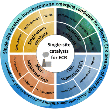
In this review, we comprehensively summarize the researches on these emerging SSCs for ECR, including their catalytic mechanisms, synthesis, optimization strategies, and remaining challenges. Furthermore, we introduce the fundamental ECR reaction mechanism and reaction descriptors to better understand and study the design and reaction mechanisms of different catalysts. We describe recent representative studies on SACs (such as carbon-based and MOF-derived), HMCs (such as phthalocyanine, porphyrin, dipyridine, and their derivatives), MOF-supported SSCs (located in different parts of MOFs) and COF-supported SSCs (such as imine-based and amine-based) to elaborate the advantages and disadvantages of SSCs for ECR (Fig. 1). Finally, we discuss the opportunities and perspectives in the application of these emerging SSCs.
2. Fundamental mechanisms of ECR
2.1. Reaction processes of ECR and catalyst selectivity
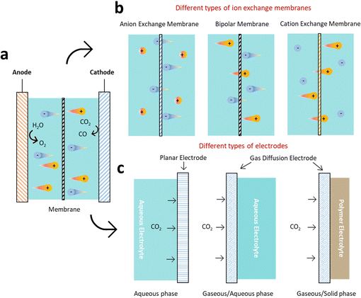
ECR is a highly intricate reaction that involves a proton-coupled multi-electron transfer process, and a wide range of products can be generated under different conditions (Fig. 2). Take reactors for example, H-cell are widely used in laboratory investigations but limited to low CO2 solubility. To overcome these limitations, flow cell with gas diffusion electrode (GDE) to improve local CO2 concentration have been implemented. However, the GDE is easy to be flooded during long-term operation. Therefore, zero-gap membrane electrode assembly reactor has been applied to overcome flooding. Besides, the electrolyte (solid/liquid electrolyte, anion/cation species, pH, etc.) and cell design (ion exchange membranes, pressure, temperature, etc.) should also be considered, because of their significant impacts on product reaction and selectivity.32Half-reactions with major reported products are outlined here, without considering the reaction conditions.33 Unless stated otherwise, all potentials in this study are versus the reversible hydrogen electrode (RHE).
| CO2 + 2H+ + 2e− → CO + H2O E0 = −0.10 vs. RHE | (1) |
| CO2 + 2H+ + 2e− → HCOOH E0 = −0.12 vs. RHE | (2) |
| CO2 + 8H+ + 8e− → CH4 + 2H2O E0 = +0.17 vs. RHE | (3) |
| 2CO2 + 12H+ + 12e− → C2H4 + 4H2O E0 = +0.08 vs. RHE | (4) |
| CO2 + 6H+ + 6e− → CH3OH + H2O E0 = +0.03 vs. RHE | (5) |
| 2CO2 + 12H+ + 12e− → C2H5OH + 3H2O E0 = +0.09 vs. RHE | (6) |
The ECR reaction in aqueous electrolytes is normally divided into four stages: dissolution, activation, hydrogenation, dimerization and polymerization (Fig. 3). The first dissolution process is essential for the ECR in the aqueous electrolyte (Stage 1). In particular, a higher solubility of CO2 usually implies a higher current density, which is vital for achieving industrially viable ECR rates. However, the dissolution and transport of CO2 are limited due to their low solubility in water under ambient conditions (34 mM). This mass transport issue can be resolved by increasing the temperature or pressure to improve the solubility of CO2 in electrolyte; using a gas diffusion flow cell to continually provide CO2 saturated electrolyte, and modifying the electrode surface to optimize the hydrophobicity and aerophilicity of the electrode.
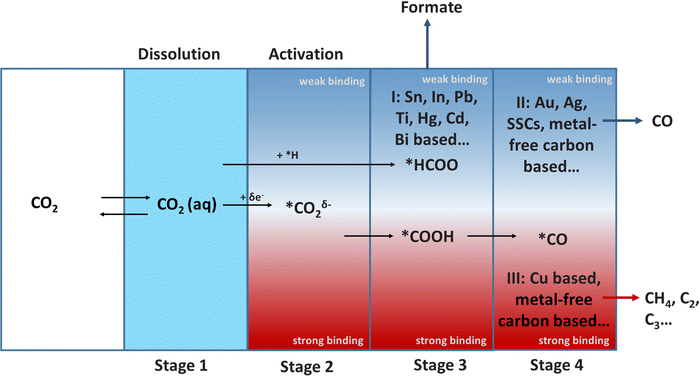 | ||
| Fig. 3 The relationship between catalyst-intermediate binding energy and selectivity of products (* represents active site on catalysts surface). | ||
CO2 is adsorbed and stabilized on the electrode surface after dissolution, resulting in two main products: *HCOO and *COOH (Stage 2 to Stage 3). The hydrogenation of *HCOO on the surface of the Group I catalysts, which have a weak binding force to *HCOO, results in HCOOH (Stage 3). *COOH is reduced to *CO (Stage 4), on the catalysts (Group II and Group III) with strong *COOH binding ability. Finally, Group II catalysts with weak binding to *CO produce CO. In contrast, Group III catalysts with strong binding with *CO prefer to undergo C–C coupling and generates C2/C2+ products. In particular, the formation of C2 and C2+ is called “dimerization and polymerization”, respectively. Furthermore, the selectivity and adsorption capacity of intermediates is the most critical research field during the entire process. The Sabatier principle should be followed in the design of catalysts, which states that the interaction between the catalysts and intermediates should not be too strong or too weak.
2.2. Descriptors of ECR catalytic activity
The market price determines whether ECR can be widely accepted, which involves cost considerations. Apart from electrolytes, separators, and catalysts associated with electrolysis device; the cost of the entire ECR process includes CO2 capture, electricity, product purification, transport, and storage. The descriptors directly related to the catalysts were the current density, Faraday efficiency (FE), energy efficiency (EE), and durability during the ECR process.The target product's current density is not only an important indicator of reaction rate, but also an important factor in terms of electricity cost. This governs the size of the electrolyzer required for a given production rate. Generally, a large electrolyzer requires high current density to cover the capital cost. Sargent et al. found that the impact of the current density on the electricity cost gradually weakened once it exceeded 300 mA cm−2.32 Therefore, a high current density (>300 mA cm−2) should be regarded as the basic standard to reduce the overall cost.
FE is another key indicator for describing the efficiency of charge (electron) transfer in systems that promotes targeted electrochemical reactions. A high FE toward a specific product could minimize the cost of product separation, which can help reduce current density and electricity cost. Thus, achieving a high FE, close to 100%, is always a worthwhile goal.
EE is the ratio of the output energy from the products of “what we gain” to the input energy from “what it cost” to produce them. Generally, the calculation of this parameter requires a comprehensive consideration of the FE and voltage efficiency of the product. Voltage efficiency reflects the part of the total input voltage that is actually used to drive the thermodynamic process, which is also related to the electricity cost. Therefore, a high EE is generally desired at low cost.
Durability is an extremely important parameter of ECR catalysts. After reaching the target current density, FE, and EE, robust stability effectively reduces the cost of maintenance and replacement. However, most current reports do not reach an ideal test time (more than 8000 h), which is important in the study of stability.
Generally, a suitable high current density (>300 mA cm−2), high FE (∼100%) and EE, and good stability (over 8000 h) are of great significance to promote the widespread application of ECR.
3. Single-atom catalysts
SACs, consisting of isolated metal atoms coordinated with non-metal atoms of supporting materials, are an emerging topic in the field of electrocatalysis.34–39 SACs have received widespread attention because of their high activity and selectivity since Zhang et al. first proposed the concept in 2011.40 Benefiting from their unique electronic structure and adjustable physicochemical properties, SACs can maximize atomic utilization efficiency and possess an unsaturated coordination environment.41,42 These unique features of SACs make them crucial for the oxygen reduction reaction,35 HER,36 ECR34 oxygen evolution reaction,37 and other catalytic processes.38,39,43 However, the high surface energy of SACs facilitates their aggregation.44 As a result, the choice of substrate is vital for the design of SACs. In particular, three families of supporting materials, carbon-based, oxide-based, and other supporting materials, are usually used for SACs applied in ECR.3.1. Carbon-based SACs
Carbon-based materials are rarely used directly in ECR because of their high CO2 adsorption energy barrier. However, their high specific surface area and strong interaction with metals are conducive to the formation of highly dispersed SACs.45 Carbon materials also have many advantageous properties, such as high conductivity and good chemical stability, which make them ideal supporting substrates for SACs.The bottom-up strategy is one of the most common methods for obtaining carbon-based SACs. In this method, metal ions are usually adsorbed on the surface of the carbon matrix; this is followed by drying and high/low-temperature thermal treatment to achieve firm anchoring.46 Zhang et al. synthesized some SACs with different metal atoms (M-SACs, M = Ru, Fe, Ni, Cr, Cu, Zn, Pt, Mn, Co, etc.) (Fig. 4a–i) by employing a “ligand-mediated” synthetic strategy.47 The strong covalent bond between the metal atoms and abundant defect sites on the surface of carbon black prevented the aggregation of metal species. Moreover, the use of carbon-supporting substrates circumvented the instability caused by high-temperature pyrolysis. Only graphite peaks were observed in the X-ray diffraction (XRD) patterns of these M-SACs, indicating that the formation of metal nanoclusters could be prevented (Fig. 4j). Different M-SACs were measured at −1.2 V to compare the effect of different central metals on the ECR performance. A “volcano curve” is displayed in Fig. 4k, showing that the appropriate interaction between intermediates and Ni atoms makes Ni-SACs the most suitable candidate for ECR compared with other as-prepared M-SACs.
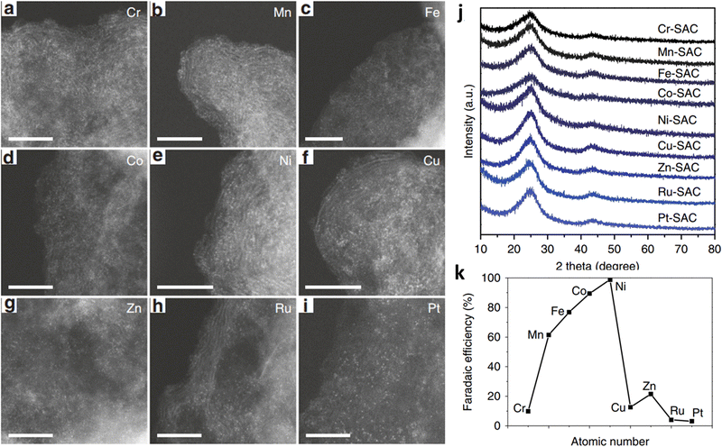 | ||
| Fig. 4 (a–i) High-angle annular dark-field scanning transmission electron microscopy (HAADF-STEM) images for M-SACs. Scale bar: 5 nm. (j) XRD patterns for the M-SACs. (k) FECO for M-SACs at −1.2 V. Reproduced with permission.47 Copyright (2019) Springer Nature. | ||
Efforts have been devoted to heteroatom doping (such as N, O, and S) in the carbon lattice to improve the catalytic performance.48 Furthermore, the N dopant could be incorporated into carbon via pyrolysis of N-containing compounds (such as dicyandiamide,47 melamine49 and urea50) with carbon matrix (such as graphene,51 carbon black,50 and graphdiyne52), and products with different architectures (such as nanotubes,53 nanosphere,54 and nanosheets53) can be obtained. The introduction of N can effectively stabilize single-atomic centres for N-doped carbon-based SACs.55,56 For example, Xie et al. enabled the activation and protonation of ECR through anchoring Snδ+ atoms on N-doped graphene.57 Furthermore, they performed in situ Fourier transform infrared (FT-IR) spectroscopy coupled with computational analysis and found that the N dopant could enhance the rate-determining HCOOH desorption step by decreasing the Gibbs free energy and elongating the bond length of Sn-HCOO− (Fig. 5a and b). Their experimental results agreed with the theoretical predictions. The as-prepared catalysts exhibited an onset overpotential below 60 mV and robust stability of more than 200 h (Fig. 5c), whereas their turnover frequency (TOF) was up to 11![[thin space (1/6-em)]](https://www.rsc.org/images/entities/char_2009.gif) 930 h−1 (Fig. 5d).
930 h−1 (Fig. 5d).
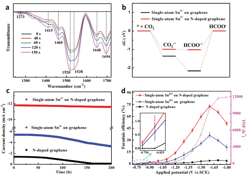 | ||
| Fig. 5 (a) In situ FT-IR spectra of Sn-SACs. (b) Free energy diagrams. (c) Chronoamperometry tests at −1.6 V vs. SCE. (d) FEHCOOH and TOF of the Sn-SACs. Reproduced with permission.57 Copyright (2019) Wiley-VCH. | ||
Li et al. found that the metal-N site could serve as the active center.54 They computationally showed that the as-prepared Co–N5 is the rate-determining center for the transformation from *CO2 to *COOH (Fig. 6a and b), which is a crucial process for CO desorption. The obtained CoN5 coordinated on hollow N-doped porous carbon spheres (Co–N5/HNPCSs) achieved a satisfactory FECO of approximately 90% (Fig. 6c and d).
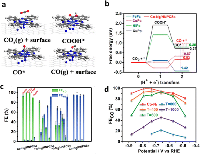 | ||
| Fig. 6 (a) Schematic diagram of ECR reaction process on M–N5/HNPCSs. (b) Calculated free energy. (c) FE of M–N5/HNPCSs. (d) FECO of Co–N5/HNPCSs-T (T = 400, 600, 800, and 1000 °C). Reproduced with permission.54 Copyright (2018) American Chemical Society. | ||
Although N can contribute to ECR through pyrrolic N, pyridinic N or graphitic N. In general, the dominant contribution is derived from metals sites.58,59 Strasser et al. found that once with the participation of metals, CO is further reduced to methanol and/or methane, indicating that the metal centers are dominant for the further reduction of intermediates during ECR by conducting controlled tests with or without metal (Fe or Mn) centers.60
Unsaturated coordination is also an important ECR performance improvement strategy for carbon-supported SSCs.61,62 The bonding of common transition metal-N-doped carbon SACs to the reaction intermediates during the ECR process is relatively weak owing to the saturated coordination environment. Therefore, properly adjusting the coordination number to form an unsaturated coordination state helps improve the adsorption capacity of intermediates. Feng et al. proposed novel Cu–N2 SACs on an ultrathin graphene matrix with unoccupied 3d orbitals of the central metal.63 A reduction in the N coordination number shortens the Cu–N bond length. Meanwhile, electron transfer from Cu–N2 to *CO2 is accelerated, thus promoting the hydrogenation of *CO2 as well as the Zn–CO2 battery performance.
Defect engineering also functions as an effective route to avoid the migration of isolated metal atoms and optimize the ECR process of carbon-based SACs.53,61 Particularly, defects not only change the coordination environment but also modify the surrounding electronic structure, thereby forming unsaturated coordination sites or vacancies. These as-obtained coordination sites or vacancies are effective for anchoring metal atoms. In addition, carbon defects can be engineered to anchor metal atoms through electron transfer between carbon and metal atoms for carbon-based materials. These carbon defects usually result in a negative charge on the surface of the carbon material, which is helpful for the uniform adsorption of metal cations.64,65 Furthermore, Wang et al. designed graphene oxide with high-density defects, which made the surface full of negative charges and helped to uniformly anchor a monolayer of Ni cations (Fig. 7a–c).66 The density of single atom active sites could be increased to achieve high catalytic activity: a nearly 95% CO selectivity at 550 mV over-potential with the assistance of carbon defects (Fig. 7d and e). Furthermore, they found that by anchoring other transition metal (TM) single atoms (Co, Mn, etc.) into layered graphene vacancies (M-NG), the HER kinetics could be effectively suppressed, and suitable CO binding could be realized.
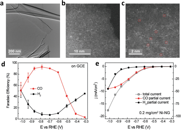 | ||
| Fig. 7 (a–c) Structure characterization of Ni–NG; (d) FEH2 and FECO and (e) the linear sweep voltammetry (LSV) curves of Ni–NG. Reproduced with permission.66 Copyright (2018) Royal Society of Chemistry. | ||
Through the design of carbon defects, the coordination number of metals can be regulated, thereby achieving the goal of anchoring more metals species with different characteristics.63,67 Shui et al. first anchored the rare-earth metal atoms Y and Sc in large carbon defects (M/NC) by adjusting the coordination anion.67 Furthermore, six M–N/M–C coordination bonds are required for anchoring each metal atom because of the large radii of Y and Sc (Fig. 8). Therefore, the catalyst exhibited a different coordination structure from that of MN4, and it exhibited excellent performance in the nitrogen reduction reaction (NRR) and ECR.
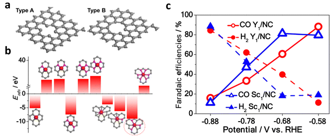 | ||
| Fig. 8 (a) Structural diagram of type A and type B substrates with small-size and large-size carbon defects, respectively. (b) Calculated adsorption energies of different active sites of Y/NC. (c) FECO and FEH2 of Y/NC and Sc/NC from −0.58 V to −0.88 V. Reproduced with permission.67 Copyright (2020) American Chemical Society. | ||
MOF-derived SACs are another type of carbon-based SACs. Recently, MOFs have already received extensive attention due to their adjustable structure, size, and tunable active sites.68–70 Furthermore, they inherit advantages from MOFs included rich three-dimensional (3D) channels and large surface areas, which are beneficial for electrolyte wettability and acceleration of mass diffusion. In addition, a favourable electronic environment of the active metal sites can be obtained in MOF-derived SACs owing to the coordination of various heteroatoms from ligands, which is beneficial for ECR performance. The most common synthetic strategy for this type of material is using a zinc-based zeolitic imidazolate framework (ZIF-8) with rich N atoms as the supporting material. After one-step pyrolysis, Zn2+ is reduced to Zn and evaporated owing to its low boiling point, leaving abundant free N atoms to stabilize other high-boiling-point metals, such as Fe,71 Co,72 Ni,73 Mn,71 and Cu.74
There are two common strategies for the synthesis of SACs from ZIF-8. The first method involves directly mixing zinc salt with other metal sources and ligands in a system followed by calcination at a high temperature to obtain SACs.75,76 The second method is to use the as-obtained ZIF-8 as a sacrificial template to mix with other metal species and form a uniform composite by ball milling,77 electrospinning,74 or other treatment,78 and removing the Zn species through high-temperature pyrolysis. Furthermore, Jaouen et al. designed an atomically dispersed metal bonded to N atoms (metal-Nx) with a similar coordination environment by ball milling and pyrolysis of ZIF-8 and M2+ acetate (Fig. 9a).77 As shown in Fig. 9b, a volcano trend was observed between the different metal centers and their activities toward CO formation. Operando X-ray absorption near-edge structure spectroscopy (XANES) and density functional theory (DFT) were performed to monitor the evolution of the active sites during ECR. The valence states of Co and Mn remained unchanged during ECR. However, Fe, Ni, and Cu were partially or completely reduced (Fig. 9c). The DFT results indicated that M2+N4–H2O played the most important role in Fe- and Co-based catalysts, whereas Ni1+N4 was considered to be the intrinsic active sites in Ni samples at 0.5–0.6 V (Fig. 9d).
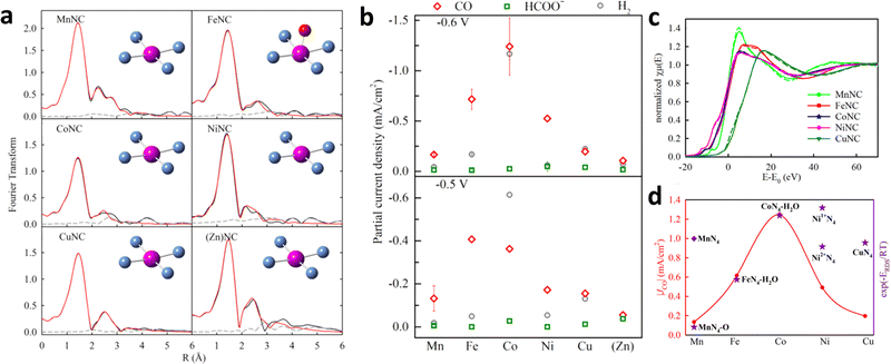 | ||
| Fig. 9 (a) K-edge EXAFS spectra of MNC. (b) Partial current densities (Jp) over the MNC catalysts for different products. (c) K-edge XANES spectra of MNC before (solid curve) and after (dashed curve) the chronoamperometry test at different potentials. (d) CO jp at −0.6 V for other MNC and computational trendency (U = −0.6 V). Reproduced with permission.77 Copyright (2019) American Chemical Society. | ||
3.2. Oxide-based SACs
In addition to carbon-based and MOF-derived SACs, metal oxides (i.e. CuO,79 FeOx,80 ZnO,81 TiO2,82 and Al2O383etc…) can also serve as supports to anchor metal atoms. For instance, the strong adsorption ability of CeO2 makes it a suitable substrate for the loading of different metal atoms. The CeO2 based SACs have been widely used in CO oxidation,84 hydrogenation,85 and ECR.86,87 Bao et al. prepared Au- and Ag-doped CeO2 with promoted ECR performance.86 Zheng et al. reported the use of Cu-doped CeO2 SACs for ECR based on the strong interactions between CeO2 and Cu.87 The introduction of Cu favored the formation of single-atom Cu with a high oxygen vacancy (Vo) number of three. In particular, this structure would exhibit a bent structure with more efficient activation toward CO2˙− when compared to single-atom Cu with Vo numbers of one and two (When the Vo is higher than three, the structure will be destabilized) (Fig. 10). Additionally, the FECH4 of as-prepared Cu-doped CeO2 SACs reaches ∼58% at −1.8 V in the H-cells.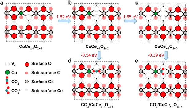 | ||
| Fig. 10 (a–c) Structural diagrams of Cu doped CeO2, with 1–3 Vo. (d and e) CO2 adsorption and activation structural diagrams of these structure. Reproduced with permission.87 Copyright (2018) American Chemical Society. | ||
3.3. Other SACs
Metal nitrides and carbides are also important substrates for single-metal atom anchoring.88–90 The p-orbits of N/C can perturb the d-orbits of the transition metal atoms, resulting in interesting regulation of the metal active sites owing to the hybridization of the orbits. Furthermore, their good electrical conductivity and physicochemical stability make them suitable supports for SACs. Jung et al. recently used theoretical calculations to study the catalytic properties of TiN, TiC, and single atoms loaded onto them in the ECR.88 TiC only needs −0.47 V limiting potential to drive the occurrence of ECR as a substrate, while TiN is easily poisoned by oxygen-containing species because of its strong affinity to O (Fig. 11a and b). In particular, the *CO binding site and strength of the catalyst changed owing to the interaction between the metal and the support. Compared with bare TiC and Ir(111), Ir on the TiC support lacks a Sigma-type interaction between Ir and *CO, thus reducing the limiting potential (Fig. 11c–f).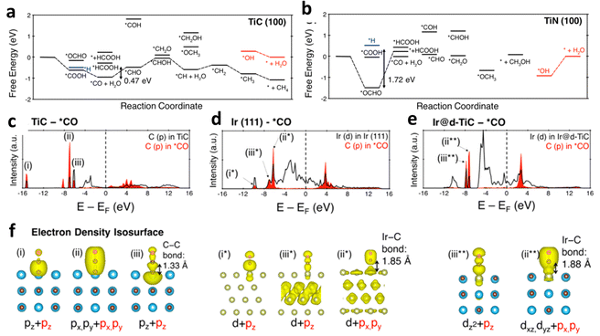 | ||
| Fig. 11 Free-energy profiles for ECR on (a) TiC and (b) TiN. Density of states of (c) TiC, (d) Ir, and (e) Ir@d-TiC interacting with *CO. (f) The electron density isosurfaces at noted panels of (c–e). Reproduced with permission.88 Copyright (2017) American Chemical Society. | ||
MoS2 is a two-dimensional (2D) layered material with many application scenarios.91,92 Various single atoms anchored on MoS2 also have good application prospects in ECR.93,94 It should be noted that MoS2 could also be employed directly for ECR, and its edges are more active than its inert surface.93,95 Activating the surface of MoS2 by anchoring various single-atomic metals could also be a good choice for enhancing the ECR performance because the stability of edges is usually limited by the edge structure and reaction conditions.96,97 By changing the mass loading of Pt, Zeng et al. prepared Pt monomers on MoS2 with different percentages of isolated Pt and neighboring Pt (Fig. 12a–c).96 These two kinds of monomer Pt with different coordination environments showed completely different selectivities towards ECR. Pt single atoms prefer the conversion of CO2 into CH3OH instead of HCOOH. However, CO2 is easily hydrogenated into HCOOH and CH3OH for neighboring Pt atoms (Fig. 12d and e).
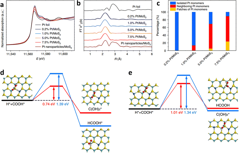 | ||
| Fig. 12 (a) Pt K-edge XANES spectra and corresponding R space (b) for different Pt/MoS2. (c) Bar graph showing the different Pt monomer contents of Pt/MoS2 samples based on HAADF-STEM results. (d and e) Steps for the hydrogenation process of Pt1/MoS2 and Pt2iii/MoS2. Reproduced with permission.96 Copyright (2018) Springe Nature. | ||
Although SACs have a number of advantages, they also face some challenges: (1) materials that can be applied as precursors are still limited. As for MOF-derived SACs, the common MOFs used are limited to ZIF-8, UiO-66-NH2, MIL-101-NH2, and ZIF-67, and the supported single metal atoms are restricted to Fe, Co, Ni, Cu, Bi, etc. Thus, efforts should be dedicated to exploring additional supporting substrates, precursors, and metal species. (2) High-temperature treatment is typically required to obtain SACs. The metal loading is limited to avoid the agglomeration of metal atoms in a high-temperature environment. Therefore, the development of novel large-scale tactics to prepare SACs with high single-metal loadings is very important. (3) Morphology regulation is an important method to improve ECR activity. However, the morphologies of SACs synthesized are usually irregularly shaped particles after high temperatures treament. The design of better-defined morphologies remains a challenge. (4) Their structural characterization techniques are often limited to particular methods such as X-ray absorption spectroscopy and spherical aberration-electron microscopy because of the low loading of single atoms and their special structural properties. Therefore, it is important to develop new characterization methods for SACs.
4. Homogeneous molecular catalysts
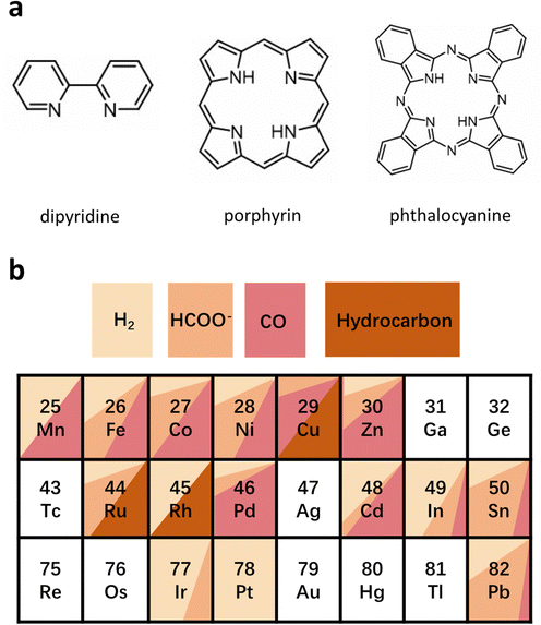
HMCs are another family of emerging catalysts, which show great potential for high selectivity and activity in the ECR because their ligands can be finely tuned easily.98,99 This kind of catalyst has a well-defined structure and active sites that allows for an in-depth study of the structural model and reaction mechanism of multi-proton–electron coupling in the ECR process, to establish a more intuitive structure–property mechanism–performance relationship. HMCs commonly used in ECR can be divided into phthalocyanine, porphyrin, dipyridine, and their derivatives (Fig. 13a).100 Different types of HMCs in ECR products usually depend on the metal active site. As shown in Fig. 13b, for Mn-, Fe-, Co-, Ni-, Zn-, and Re-based HMCs, CO is the main product, whereas for Ir- and In-based HMCs are more inclined to produce formic acid. For Cu-, Ru-, and Rh-based HMCs, hydrocarbons occupy a large proportion of the products.100–105 However, they all face the challenges of aggregation and demetallation owing to the solubility and side reactions in the reaction process regardless of the metal-based HMCs.106,107Modifying the surface of HMCs is an important strategy to alleviate the aggregation issue.108,109 HMCs are more prone to agglomeration in aqueous solutions than in organic solutions because of their special synthesis environment. This reunion further blocks or severely hinders the mass transfer process around the active sites, thereby reducing the stability decay and current density. This problem can be addressed by introducing hydrophilic groups. Furthermore, Officer et al. effectively improved the solubility of the catalyst by introducing alkoxy groups to CoPc (CoPc-A) (Fig. 14a), which prevented its agglomeration. However, the inherent activity of the catalyst was greatly enhanced (TOF of ∼5 s−1 at an overpotential of 0.480 V). In addition, the as-prepared catalysts showed stable CO conversion for more than 30 h (Fig. 14b–d).108
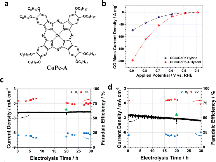 | ||
| Fig. 14 (a) Structural diagram of CoPc-A. (b) Total current density (Jt) of chemically converted graphene/CoPc-A (CCG/CoPc-A) and CCG/CoPc hybrids. Stability test of (c) CCG/CoPc and (d) CCG/CoPc-A at same potential (−0.69 V). Reproduced with permission.108 Copyright (2019) American Chemical Society. | ||
Using a water-soluble HMC-modified electrode also alleviates the aggregation of the catalysts. Wang et al. effectively suppressed HER in the aqueous solution by depositing water-soluble 1,10-phenanthroline–Cu (phen–Cu) molecular complexes on a mesoporous graphene electrode.109In situ attenuated total reflection infrared (ATR-IR) study revealed that Cu molecules would heterogenize near the electrode during the test, resulting in an increase in electron density under catalytic conditions (Fig. 15a and b). Furthermore, they found that the phen–Cu surface structure of the graphene electrode affected charge distribution during the ECR process based on the infrared signal. The change in the applied potential confirms that the external electric field is crucial for the reversible heterogenization of Cu molecules (Fig. 15c). In addition, more electrons would aggregate on the ligands, owning to the reduction of the potential, thus leading to a blue shift in the IR spectra (Fig. 15d). Furthermore, the mesostructure of the graphene matrix limits mass transfer from the bulk solution to the electrode, thus suppressing the HER and greatly improving the selectivity of ECR. The modified catalysts exhibited enhanced TOF (45 s−1 at −1.0 V) and high FECO around 90% at −0.6 V. These results emphasize that the modification of the electrode surface with a suitable molecular catalyst can also achieve high ECR selectivity.
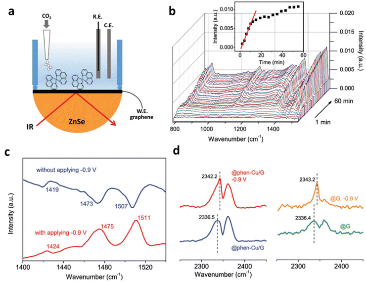 | ||
| Fig. 15 (a and b) In situ Raman spectrum tests of Ni–TAPc on gold electrode under (a) Ar and (b) CO2. Electrochemical performance: (c) FECO and Jt at different potentials acquired on a carbon cloth electrode in CO2-saturated 0.5 M KHCO3 solution. (d) TOF of Ni–CNT–CC (Ni–CNT represents Ni–TAPc anchored on carbon nanotubes) compared with other CO2-to-CO catalysts. Reproduced with permission.109 Copyright (2018) Wiley-VCH. | ||
The reduction and demetallation of center metals are common side reactions of HMCs during the ECR process.110–112 Actually, proper metal reduction could be helpful to the activation of ECR. Based on operational spectroscopy and electrochemical kinetics studies, Liu et al. found that Ni+ produced by in situ reduction of Ni2+ in Ni(II) 2,9,16,23-tetra(amino) phthalocyanine (Ni–TAPc) is very active for ECR activation and can act as the intrinsic catalytic sites for ECR.113 When the cathode potential was increased above 0.57 V under Ar atmosphere, a red-shift occurred for the Ni–N vibration in Ni–TAPc. Electrons were transferred to the Ni 3d orbital during the test, which led to the reduction of Ni2+ to Ni+ (Fig. 16a). Once CO2 was pumped into the system, the vibration of Ni–N will return to its pristine state (Fig. 16b), and no longer change with the changing cathode potential (from open circuit potential to 0.37 V). The quick oxidation of Ni+ is believed to be more helpful than that of Ni2+ for the activation of CO2 because it overlaps better with the C 2p* orbital in CO2. Furthermore, the developed Ni SSCs showed high ECR activity with a FECO of 99% and TOF of 100179 h−1 (Fig. 16c and d).
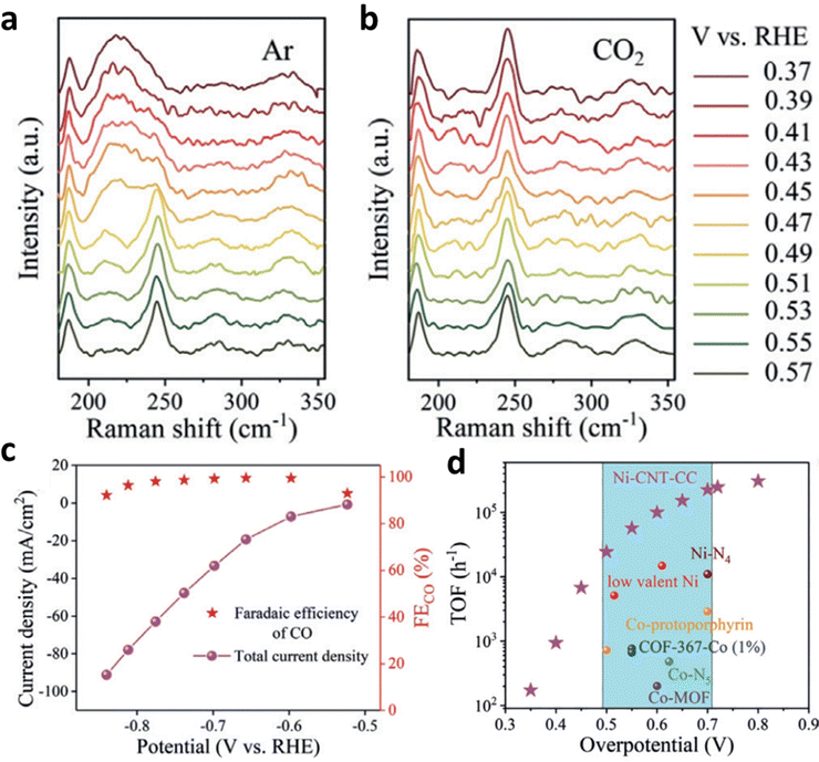 | ||
| Fig. 16 (a and b) Raman spectra of Ni–TAPc collected on an Au electrode at various potentials under (a) Ar (1.0 atm) and (b) CO2 (1.0 atm). Electrochemical performance: (c) FECO and Jt at different potentials acquired on a carbon cloth electrode in CO2-saturated 0.5 M KHCO3 solution. (d) The TOF of Ni–CNT–CC (Ni–CNT represents Ni–TAPc anchored on carbon nanotubes) compared with those of other CO2-to-CO reduction catalysts. Reproduced with permission.113 Copyright (2020) Wiley-VCH. | ||
However, the irreversible metal reduction or demetallation reaction can easily lead to the formation of large-size metal particles, which would lead to the decay of the catalytic activity. Wang et al. designed a controlled ECR experiment with three Cu complexes: CuPc, Cu-based HKUST-1, and [Cu(cyclam)]Cl2 (Fig. 17a–c).110 They found that the CuPc exhibited the highest activity and selectivity among all catalysts; its partial current density for methane and FECH4 reached 13 mA cm−2 and 66% at −1.06 V, respectively (Fig. 17d and e). Additionally, the CuPc exhibited the highest activity and selectivity among all the catalysts. It showed high partial current density for methane (13 mA cm−2) and FECH4 (∼70%), respectively (Fig. 17d and e). Operando XANES and extended X-ray absorption fine structures (EXAFS) were applied to probe the reconstruction of the local coordination environment during the ECR. However, during the ECR process, the CuPc molecules underwent reconstruction and produce nearly 2 nm metallic Cu clusters. Additionally, the Cu nanocluster quickly reverted to the pristine structure after applying the negative electrode potential (at 0.64 V) (Fig. 17f–h). On the contrary, for [Cu(cyclam)]Cl2 and HKUST-1, the complexes decomposed and agglomerated into larger Cu particles, which also explains their poor ECR activities. They applied DFT to examine the thermal kinetics of the reductive demetalization and recovery of the CuPc structure to better study the reconstruction process. The calculations show that the demetallization process has lower reduction potential than those of the other two catalysts. This indicates that CuPc has the most stable structure among all Cu-based catalysts. Thermodynamic calculations also revealed that the binding affinity of the metal ions of the copper complex with the ligands affects the threshold potential and reversibility of the reductive demetallization process, influencing the ECR performance further.
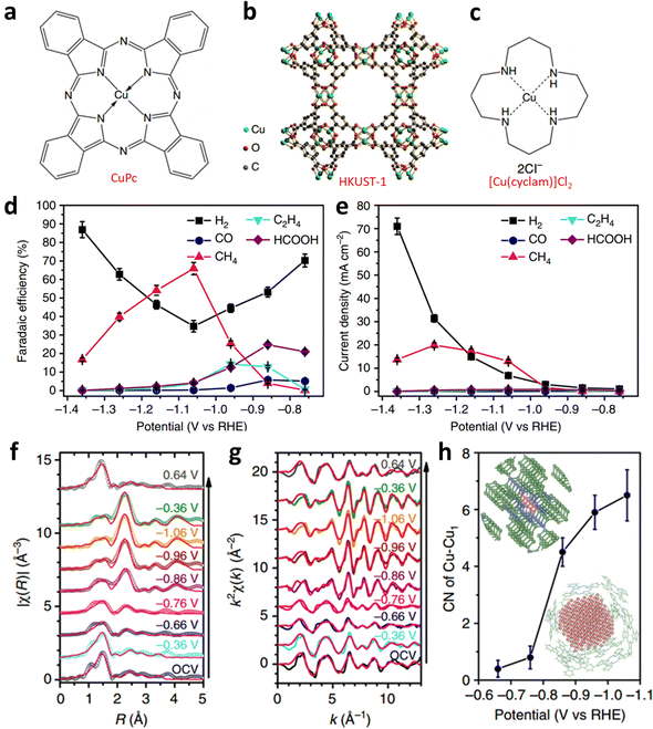 | ||
| Fig. 17 Structural diagram of (a–c) three Cu complexes. (d) Potential-dependent FE and (e) jp of products for ECR catalyzed by CuPc. Fitted (f) R-space and (g) k-space EXAFS spectra of CuPc. (h) First-shell Cu–Cu coordination numbers of CuPc from −1.5 to −0.65 V. Reproduced with permission.110 Copyright (2018) Springer Nature. | ||
For HMCs, their ligands can be easily fine-tuned during the synthesis process, giving them greater controllability and advantages in performance and model establishment. Their good solubility in organic solvents and water also expands their application scenarios, though they still face many challenges: (1) the low loading capacity of HMCs makes them insensitive to traditional characterization methods. However, HMC must prioritize selectivity and stability. (2) The HMCs currently used in the ECR direction are limited to bipyridine, porphyrin, and phthalocyanine derivatives. Thus, the development of HMCs with novel ligands and product selectivity is critical. (3) The methods for HMC immobilization are currently limited (such as π–π interactions, physical confinement, and covalent bonding). Stability is another big challenge; the choice of immobilization needs to consider the problems of catalyst leaching, demetallation, aggregation, and steric hindrance of ligands. Furthermore, it will be necessary to further develop assembly technology and introduce more kinds of ligands into the skeleton to help improve the diversity and mechanism research of molecular catalysts in the future.
5. MOF-supported single-site catalysts
MOFs are emerging porous coordination polymers constructed from metal ions, clusters, and ligands. They have attracted considerable attention for broad applications owing to their large surface areas, well-defined metal nodes, and adjustable pore dimensions.114,115 In addition, they also have attracted great interest in ECR because of their uniform and unique geometry and electronic structure.116–119 In contrast to the MOFs that serve as the precursor for SACs in Section 3.1, the MOFs in this section act as supporting substrates for atomic metal sites. Particularly, apart from only being applied to avoid agglomeration and deactivation through the physical separation of individual catalyst molecules compared with other porous supports, MOFs can also be used for an in-depth study of the ECR mechanism by deeply exploring the relationship of structure–property relationship. The highly ordered arrangement of metal nodes and organic ligands with sub-nanometer-sized pores enables MOFs to disperse atomic-level metal sites altogether. Thus, in this section discusses the SSCs located in the metal nodes, ligands, and pores.5.1. SSCs located in metal nodes
Anchoring a single atomic site on the metal nodes achieves a uniform distribution and avoids aggregation because of the uniform distribution of metal nodes in MOFs. Metal nodes are usually built by metal oxide clusters such as ZrO6–8 and Zr6O4(μ3-OH)4, which act as binding sites on MOFs.109,120 Their unsaturated coordination environment makes them ideal substrates for anchoring isolated metal atoms. Furthermore, Gu et al. prepared TCPP(Co)/Zr-BTB MOF nanosheets by constructing an interaction between the Zr6 clusters of Zr-BTB MOF (BTB = one, three, 5-tris(4-carboxyphenyl)benzene) and carboxyl groups of Co porphyrin [TCPP(Co)] (Fig. 18a).18 The obtained 2D structure could avoid the stacking of cobalt porphyrin and guarantee the full exposure of active sites to CO2, which greatly optimized the ECR efficiency with a 77.2% FECO and a 7 mA cm−2jt (Fig. 18b and c). Moreover, they introduced different ligands to Zr6 groups, p-(aminomethyl)benzoic acid (PABA), p-sulfobenzoic acid potassium (PSBA), and p-sulfamidobenzoic acid (PSABA), to create different microenvironments around TCPP(Co). After modification, the as-prepared TCPP(Co)/ZrBTB not only inherited the pristine structure, but also maintained the uniform nanosheet morphology. The HER has been inhibited, and the FECO of the PSABA-modified catalysts reached 85.1%, thus benefiting from the steric effect and tighter coverage of Zr6 clusters derived from modifier molecules (Fig. 18d and e).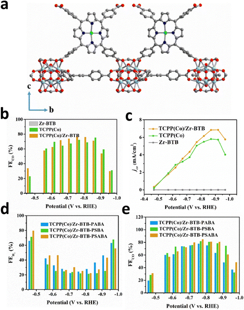 | ||
| Fig. 18 (a) Schematic diagram of TCPP(Co)/Zr-BTB. (b) FECO and (c) CO Jp for all catalysts at different applied voltages. (d) FEH2 and (e) FECO for PABA-, PSBA-, and PSABA-modified TCPP(Co)/Zr-BTB at different potentials. Reproduced with permission.18 Copyright (2019) Wiley-VCH. | ||
Using an external electric field to promote the coordination of molecules with single metal sites and MOFs is also an effective method to prepare SSCs located on MOF nodes. Furthermore, Joseph et al. realized the heterogeneous electrochemical conversion of carbon dioxide (∼100% FE(CO+H2)) to fuel under high flux conditions, by electrophoretic deposition of a large number of Fe-porphyrin (Fe-TPP) based MOF-525 (Fe_MOF-525) on fluorine-doped tin oxide (FTO), (Fig. 19a).22 Additionally, they achieved a high concentration of Fe-TPP adsorption, equivalent to approximately 900 layers of Fe-TPP adsorbed on the FTO surface by selecting appropriate MOFs (Fig. 19b). In addition to the introduction of Fe single-site molecular catalysts, the ECR selectivity of the original electrodes could be optimized. Moreover, the abundant nanoscale porosity of MOFs is also conducive for solvents, reactants, and electrolytes to access catalytic sites. Fe-TPP anchored on the metal nodes of MOF-525 serves as both an electrocatalyst and a redox-hopping conduit for transporting reduction equivalents to catalytic sites beneath the surface of the electrode.
 | ||
| Fig. 19 (a) FE over approximately 4 h of bare FTO, Fe_MOF-525 with/without 2,2,2-trifluoroethanol (TFE). (b) Proposed ECR mechanism on the Fe porphyrin-based MOF. Reproduced with permission.22 Copyright (2015) American Chemical Society. | ||
5.2. SSCs located in ligands
Single-site metal atoms can also be designed in the ligands of MOFs.121 Through ingenious design of ligands, different binding sites (i.e. N, O, P, and S) can be incorporated in ligands to anchor single-atomic metal in the MOFs. Therefore, choosing a ligand with appropriate binding sites is critical for the incorporation of single-site active sites into MOFs. Wang et al. prepared cobalt protoporphyrin (CoPP) installed on 4′-(4-benzoate)-(2,2′,2′′-terpyridine)-5,5′′-dicarboxylate (TPY) and BTB on metal–organic layers (MOLs) as SSCs.122 Both the pyridinium group and CoPP on the TPY linkers could activate CO2 by constructing [pyH+–−O2C–CoPP] adducts when these catalysts were applied for the ECR, which enhances the ECR activity and inhibit the HER process (Fig. 20a). After 1 e− reduction of CoPP, CO2 is adsorbed and transferred to [HO2C–CoPP]0, which competes with [H–CoPP]0 which prefers the HER. The ECR is more favorable than the HER pathway in the catalysts because the pre-assembled pyridine moiety stabilizes the [pyHO2C–CoPP]0 clusters, resulting in a higher CO/H2 selectivity than BTB-MOL-CoPP (Fig. 20b). Moreover, the synergistic stabilization effect from the [pyH+–−O2C–CoPP] resulted in a high selectivity for CO production at around −0.9 V, corresponding to a high TOF (0.4 s−1). As shown in Fig. 20c, only HER activity was observed when the same test was carried out using catalysts (TPY-MOL and BTB-MOL) without CoPP, indicating that CoPP is the dominant active sites for ECR.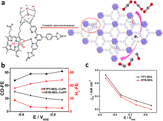 | ||
| Fig. 20 (a) Schematic diagram of TPY-MOL-CoPP and the synergetic role of two different moieties (CoPP and TPY) for ECR. (b) FECO and FEH2 as well as (c) HER current density for TPY- and BTB-MOL-CoPP. Reproduced with permission.122 Copyright (2019) American Chemical Society. | ||
Lan et al. synthesized polyoxometalate–metalloporphyrin organic frameworks (PMOFs) coordinated by M-TCPP linkers (tetrakis[4-carboxyphenyl]-porphyrin-M) and reductive Zn-ε-Keggin clusters via a hydrothermal method.123 The obtained PMOFs had the general formula [PMoV8MoVI4O35(OH)5Zn4]2[M-TCPP][2H2O][1.5TBAOH] (M = Fe, Co, Ni, and Zn, TBAOH = tetrabutylammonium hydroxide) (Fig. 21a). In this structure, the four Zn-ε-Keggin chains were assembled by M-TCPP via the coordination connection between the carboxyl group and Zn clusters. M-TCPP and Zn clusters both served as electron donors and ECR active sites (Fig. 21b). The PMOFs demonstrated excellent performance in ECR, especially for the Co-PMOF, achieving a high FECO of 99%, a high TOF (nearly 1700 h−1), and robust stability over 35 h (Fig. 21c).
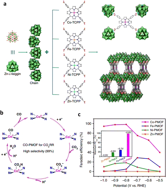 | ||
| Fig. 21 (a) Structural diagram of M-PMOFs. (b) Proposed ECR mechanism on Co-PMOF. (c) FECO of M-PMOFs. Reproduced with permission.123 Copyright (2018) Springer Nature. | ||
5.3. SSCs located in nanopores
Tunable nanopores in MOFs can also be used to anchor single-site atoms of appropriate size. Lan et al. implanted metallocene (MCp2, Cp stands for cyclopentadienyl, M = Fe, Ni, Co) into the pores of metalloporphyrin-based MOF-545 via chemical vapor deposition by taking advantage of the high porosity, large pore size, and excellent physical/chemical stability of MOF-545 (Fig. 22a).21 Furthermore, experiments and DFT calculations revealed that in the obtained MCp2@MOF-545 composite material, the π-electron cyclopentadienyl ring system might be overlapped with the π-electron system of porphyrin. In addition, MCp2 can be used as an electron donor and carrier to form a continuous electron transport channel in MOF-545. In addition, the strong binding interaction with metalloporphyrin in the ECR process greatly reduces the adsorption energy of CO2, thus enhancing ECR activity (Fig. 22b). CoCp2@MOF-545-Co (97% at −0.7 V), FeCp2@MOF-545-Co (94.1%, at −0.8 V), and NiCp2@MOF-545-Co (82.6%, at −0.8 V) all exhibited high FECO specifically (Fig. 22c). The loading of single active sites into the nanopores of MOFs opens up new possibilities to promote the ECR process and inspires the development of high-selectivity ECR electrocatalysts.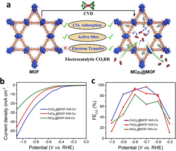 | ||
| Fig. 22 (a) The comparison of MCp2@MOF and MOF in ECR. (b) LSV and (c) FECO for MCp2@MOF-545-Co. Reproduced with permission.21 Copyright (2020) Elsevier Ltd. | ||
SSCs anchored on MOFs have various adjustable properties because of their adjustable structure and porosity. Furthermore, they have become an important research topic for ECR. However, they also face many challenges: (1) the introduction of single-site active centers in MOFs, either in the pores or anchored on the metal nodes, may hinder the mass transfer process. (2) It is difficult to achieve precise control of catalysts and high single-site metal loading because of the mutual restriction of MOFs and single-site active centers. (3) It is difficult to achieve precise positioning and structural analysis of single-site catalysts because of the limited characterization technology. Therefore, efforts should be dedicated to developing more in situ and ex situ spectroscopic characterizations as well as theoretical simulations and calculations. Only in this way can we realize the precise control of SSC-anchored MOFs and unlock their great potential for ECR.
6. COF-supported single-site catalysts
COFs are entirely made up of light elements linked together by strong covalent bonds, and are extensively applied in gas transportation and conversion because of their numerous pores and interfaces that interact with gas molecules.124–126 Moreover, COFs have been considered a promising platform for supporting SSCs for ECR because of their permanent porosity and tunable building blocks, which are conducive to the adsorption and diffusion of CO2.By incorporating metal macrocyclic units (such as porphyrin,127 phthalocyanine128etc.), the advantages of both molecular (high ECR selectivity) and heterogeneous catalysts (stable in water) can be achieved simultaneously in the obtained COFs. For instance, by using imine bonds to link cobalt porphyrin catalysts and organic struts, Yaghi and his co-workers reported a modular optimization strategy of COFs for ECR (Fig. 23a).129 The covalent coordination of cobalt porphyrin within a COF was shown to affect the ECR mechanism in electrochemical experiments. The as-obtained COF-367-Co catalyst showed a high FECO (90%), a high turnover number of nearly 300![[thin space (1/6-em)]](https://www.rsc.org/images/entities/char_2009.gif) 000, and an impressive TOF of approximately 9400 h−1 under neutral conditions (Fig. 23b and c).
000, and an impressive TOF of approximately 9400 h−1 under neutral conditions (Fig. 23b and c).
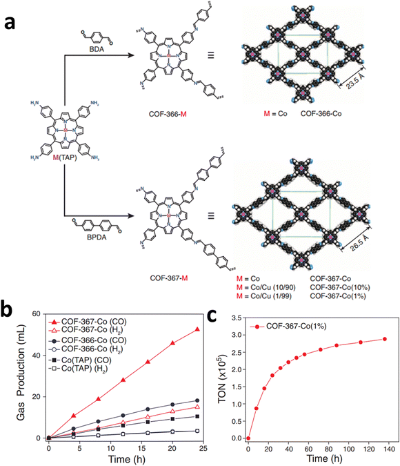 | ||
| Fig. 23 (a) Design of metalloporphyrin-based COFs. (b) Long-term electrolysis at −0.67 V and gas production of different Co COFs catalysts. (c) Stability test and TON of Co COFs catalysts at −0.67 V. Reproduced with permission.129 Copyright (2015) American Association for the Advancement of Science. | ||
COFs constructed by amine bonds have also received increasing attention for ECR applications because of their robust stability in aqueous electrolytes. Deng et al. synthesized COF-300-AR and COF-366-M-AR with amine linkages with both 3D and 2D structures by reducing the COFs with imine linkers.24 Spectroscopic results confirmed that the synergetic effect of the COFs and the Ag electrode at their interface was responsible for the enhanced ECR performance (Fig. 24a). In addition, the amine linkage showed a robust structure in 6 M HCl and 6 M NaOH (Fig. 24b). In particular, the COF-300-AR deposited on Ag electrode promoted the ECR with a FECO of 80% at −0.85 V and 53% at −0.7 V (Fig. 24c).
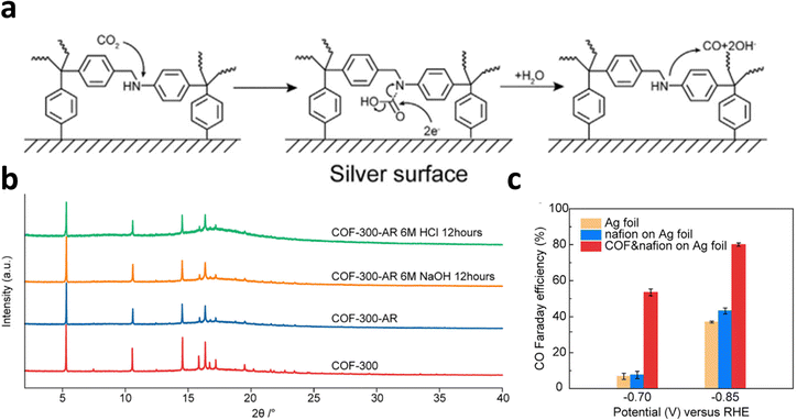 | ||
| Fig. 24 (a) Schematic diagram of ECR at the interface of electrode. (b) XRD of COFs samples in HCl or NaOH solution. (c) FECO of the different COFs electrodes at −0.70 V and −0.85 V. Reproduced with permission.24 Copyright (2018) Elsevier Ltd. | ||
In general, COF-supported SSCs have unique advantages for studying the structure–performance relationship because of their regular pores, adjustable pore sizes, high surface areas, and high adjustability. The activity and selectivity of ECR can also be enhanced by introducing different building blocks into the COFs. However, COF-supported SSCs also face many challenges: (1) the synthesis and collection of COFs are complicated and costly, which limits their large-scale synthesis. In addition, the good dynamic covalent nature of C![[double bond, length as m-dash]](https://www.rsc.org/images/entities/char_e001.gif) N and B–O would also result in stability issues, limiting their application under harsh conditions. (2) The conductivity of the COFs is in the range of insulators and semiconductors. Further improvement in its electrical conductivity is of great significance for electrocatalysis. (3) The current ECR performance of COF-supported SSCs remains limited. Therefore, it is desirable to improve intrinsic ECR performance and selectivity. More research is needed to determine the exact structure-ECR performance relationship of COF-supported SSCs, which is beneficial for further performance optimization. As technology grows by leaps and bounds, COF-supported SSCs with high ECR performance may play a more significant role in the future.
N and B–O would also result in stability issues, limiting their application under harsh conditions. (2) The conductivity of the COFs is in the range of insulators and semiconductors. Further improvement in its electrical conductivity is of great significance for electrocatalysis. (3) The current ECR performance of COF-supported SSCs remains limited. Therefore, it is desirable to improve intrinsic ECR performance and selectivity. More research is needed to determine the exact structure-ECR performance relationship of COF-supported SSCs, which is beneficial for further performance optimization. As technology grows by leaps and bounds, COF-supported SSCs with high ECR performance may play a more significant role in the future.
7. Conclusion and perspective
ECR is critical for promoting the carbon cycle and reducing the greenhouse effect. Owing to their highly adjustable structure and clear active center, SSCs, including SACs, HMCs, MOF-supported SSCs, and COF-supported SSCs, have attracted substantial attention in ECR studies. The topic of emerging SSCs for ECR was comprehensively discussed in this review by investigating the reaction mechanisms, synthetic tactics, and optimization methods. We also summarized the typical examples from recent years to discuss the merits and shortcomings of SSCs for ECR (Table 1). In addition, we discussed solutions for these challenges, including the various obstacles and prospects in the application of these emerging SSCs. Although many achievements have already been made, further research is required to realize the industrialization of SSCs for ECR.| Catalyst | Main product | Maximum FE | Reaction condition | Ref. |
|---|---|---|---|---|
| Note. a, b, c and d indicate that catalysts are SACs, HMCs, MOF-supported SSCs and COF-supported SSCs, respectively. jp means partial current density, and jtol means total current density. | ||||
| aBi SACs | CO | 97% (−0.5 V, jp = 3.9 mA cm−2) | H-cell, 0.1 M NaHCO3 | 130 |
| aCo SACs | CO | 97% (−0.6 V, jp ≈ 22.5 mA cm−2) | H-cell, 0.1 M KHCO3 | 131 |
| aNi SACs | CO | ∼99% (−0.681 V, jp = 100 mA cm−2) | H-cell, 0.5 M KHCO3 | 50 |
| aPd–NC | CO | 55% (−0.5 V, jp ≈ 0.57 mA cm−2) | H-cell, 0.5 M NaHCO3 | 132 |
| aCu SACs | CH3OH, CO | 44% (methanol, −0.9 V, jtol ≈ 90 mA cm−2); 56% (CO, −0.9 V, jtol ≈ 90 mA cm−2) | H-cell, 0.1 M KHCO3 | 47 |
| aNi-SAC-2.5 | CO | 98.9% (−1.2 V, jtol ≈ 7.5 mA cm−2) | H-cell, 0.1 M KHCO3 | 133 |
| aFe–NC | CO | 93% (∼−0.6 V, jp = 2.8 mA cm−2) | H-cell, 0.1 M KHCO3 | 72 |
| aCu–CeO2-4% | CH4 | ∼58% (−1.8 V, jtol = 70 mA cm−2) | H-cell, 0.1 M KHCO3 | 54 |
| bCuPc | CH4 | ∼66% (−1.06 V, jp = 13 mA cm−2) | H-cell, 0.5 M KHCO3 | 134 |
| bNiTAPc | CO | 99% (∼−0.74 V, jtol = 32.3 mA cm−2) | H-cell, 0.5 M KHCO3 | 135 |
| bCoPc-Pyr | CO | 95% (−0.7 V, jtol = 2.5 mA cm−2) | H-cell, 0.05 M K2CO3 | 136 |
| bCr-bipyridine based HMCs | CO | ∼96% (−2.1 V vs. Fc+/Fc) | H-cell, 0.1 M TBAPF6/DMF, 0.62 M PhOH | 137 |
| bMn-bipyridine based HMCs | HCOOH | 90% (−1.77 V vs. Fc+/Fc) | H-cell, 0.2 M Bu4NBF4/MeCN, 2.0 M TFE | 138 |
| bNi-complexes | CO | 87% (−2.44 V vs. Fc+/0) | 3-Neck pear-shaped glass cell, 0.1 M Bu4NBF4/CH3CN | 139 |
| bRe-bipyridine based HMCs | CO | 81% (−2.8 V vs. Fc0/+) | H-cell, MeCN (0.1 M [nBu4N][PF6]) | 140 |
| bCu-porphyrin based HMCs | CH4+ C2H2 | 44% (−0.976 V, jp = 13.2 + 8.4 mA cm−2) | H-cell, 0.5 M KHCO3 | 141 |
| cCu2(CuTCPP) | HCOOH | 68.4% (−1.55 V vs Ag/Ag+, jp ≈ 3 mA cm−2) | H-cell, 1 M H2O and 0.5 M EMIMBF4 | 142 |
| cCo-MOF | CO | 98.7% (−0.8 V, jp = 18.8 mA cm−2) | H-cell, 0.5 M KHCO3 | 123 |
| cMOL-CoPP | CO | 92.2% (−0.86 V, jp = 1314 mA mg−1) | H-cell, 0.1 M NaHCO3 | 122 |
| cCoCp2@MOF-545-Co | CO | 97% (−0.7 V jp = 15 mA cm−2) | H-cell, 0.5 M KHCO3 | 21 |
| cTCPP(Co)/Zr-BTB-PSABA | CO | 85.1% (−0.769 V, jtol = 6 mA cm−2) | H-cell, 0.5 M KHCO3 | 143 |
| cPcCu–O8–Zn | CO | 88% (−0.7 V, jp = 2.5 mA cm−2) | H-cell, 0.1 M KHCO3 | 143 |
| dCOF-366-Co | CO | 90% (–0.67 V, jp ≈ 80 mA mg−1) | 0.2 M K2HPO4 buffer, 0.5 M KHCO3 | 23 |
| dCo-porphyrin based COF | CO | 95% (−0.7 V, jp ≈ 4.5 mA cm−2) | H-cell, 0.5 M KHCO3 | 127 |
| dCOF-300-AR | CO | 80% (−0.85 V) | H-cell, 0.1 M KHCO3 | 24 |
| dCo-porphyrin based COF | CO | 95% (−0.6 V) | 3-Compartment cell, 0.5 KHCO3 | 144 |
| dCOF-366-Co | CO | 87% (−0.67 V, 65 mA mg−1) | H-cell, 0.5 KHCO3 | 145 |
| dFe-porphyrin based COF | CO | ∼80% (−2.2 V vs. Ag/AgCl) | One-compartment cell, 0.5 M TFE/MeCN | 146 |
(1) Conducting in-depth fundamental research on basic catalyst theory
Theoretical knowledge on electrochemistry, surface chemistry, materials science, and simulation and calculations is the basis for the development of ECR science, which is an interdisciplinary subject. The structure and performance of SSCs are significantly affected by their coordination structures. An in-depth understanding of the chemistry involved in the design of more effective and stable catalysts can be achieved by more comprehensively studying the controllable structural characteristics of SSCs and the relationship between their coordination structure and performance.(2) Exploring a low-cost and highly controllable synthetic strategy
Although numerous studies on SSCs have been conducted in the past decade, further research is required before SSCs can be used for practical applications. In addition, owing to the limitations of the synthesis method, SSCs are usually composed of particles. Therefore, SSCs with specific morphologies, more active sites, high surface areas, and high stability must be fabricated by using a highly controllable method. In addition, to realize the commercialization and large-scale application of SSCs, issues such as cost and environmental protection should be considered in these synthesis methods.(3) Developing more practical applications
In addition to the impacts of catalysts, the ECR reaction highly depends on the conditions of the external equipment, such as the electrolyte (anion/cation species, concentration, pH, and phase state), ion-exchange membrane (cation-exchange/anion-exchange/bipolar membrane), electrolytic cells (H cells and flow cells), and gas diffusion electrodes. Therefore, more practical devices should be developed to adapt to different situations for ECR and promote the practical use of SSCs.(4) Clarifying the catalytic mechanism through in situ/ex situ characterization and theoretical calculations
ECR is a reaction involving multiple electrons. In particular, the isolated active center atoms of the SSCs make the ECR mechanisms different from those of traditional bulk catalysts. Thus, the combination of in situ/ex situ characterizations and DFT calculations are helpful for in-depth observations and study of the surface reconstruction, ion diffusion, and electronic behavior of the catalyst during the reaction process and for the study of the specific reaction behavior of the intrinsic catalytic site. The SSC design and ECR mechanism can be understood by performing more advanced characterizations and well-developed calculations.Conflicts of interest
There are no conflicts to declare.Acknowledgements
This work was supported by the National Key Research and Development Program of China (2020YFA0715000), the National Natural Science Foundation of China (52127816, 51832004), the China Postdoctoral Science Foundation (2022T150502), National Energy-Saving and Low-Carbon Materials Production and Application Demonstration Platform Program (TC220H06N), and Hainan Provincial Joint Project of Sanya Yazhou Bay Science and Technology City (2021CXLH0007).Notes and references
- F. W. Li, A. Thevenon, A. Rosas-Hernández, Z. Y. Wang, Y. L. Li, C. M. Gabardo, A. Ozden, C. T. Dinh, J. Li, Y. H. Wang, J. P. Edwards, Y. Xu, C. McCallum, L. Z. Tao, Z. Q. Liang, M. C. Luo, X. Wang, H. H. Li, C. P. O'Brien, C. S. Tan, D. H. Nam, R. Quintero-Bermudez, T. T. Zhuang, Y. G. C. Li, Z. J. Han, R. D. Britt, D. Sinton, T. Agapie, J. C. Peters and E. H. Sargent, Nature, 2020, 577, 509–513 CrossRef CAS PubMed.
- F. P. G. de Arquer, C. T. Dinh, A. Ozden, J. Wicks, C. McCallum, A. R. Kirmani, D. H. Nam, C. Gabardo, A. Seifitokaldani, X. Wang, Y. G. C. Li, F. W. Li, J. Edwards, L. J. Richter, S. J. Thorpe, D. Sinton and E. H. Sargent, Science, 2020, 367, 661 CrossRef PubMed.
- S. Ren, D. Joulie, D. Salvatore, K. Torbensen, M. Wang, M. Robert and C. P. Berlinguette, Science, 2019, 365, 367–369 CrossRef CAS PubMed.
- W. Zhang, C. Huang, J. Zhu, Q. Zhou, R. Yu, Y. Wang, P. An, J. Zhang, M. Qiu, L. Zhou, L. Mai, Z. Yi and Y. Yu, Angew. Chem., Int. Ed., 2022, 61, e202112116 CAS.
- K. P. Kuhl, E. R. Cave, D. N. Abram and T. F. Jaramillo, Energy Environ. Sci., 2012, 5, 7050–7059 RSC.
- J. Qiao, Y. Liu, F. Hong and J. Zhang, Chem. Soc. Rev., 2014, 43, 631–675 RSC.
- W. Zhang, C. Huang, Q. Xiao, L. Yu, L. Shuai, P. An, J. Zhang, M. Qiu, Z. Ren and Y. Yu, J. Am. Chem. Soc., 2020, 142, 11417–11427 CrossRef CAS PubMed.
- Y. Hori, A. Murata, R. Takahashi and S. Suzuki, J. Am. Chem. Soc., 1987, 109, 5022–5023 CrossRef CAS.
- J.-W. Chen, S.-H. Hsieh, S.-S. Wong, Y.-C. Chiu, H.-W. Shiu, C.-H. Wang, Y.-W. Yang, Y.-J. Hsu, D. Convertino, C. Coletti, S. Heun, C.-H. Chen and C.-L. Wu, ACS Energy Lett., 2022, 7, 2297–2303 CrossRef CAS.
- L. Chen, Z. Qi, X. Peng, J.-L. Chen, C.-W. Pao, X. Zhang, C. Dun, M. Young, D. Prendergast, J. J. Urban, J. Guo, G. A. Somorjai and J. Su, J. Am. Chem. Soc., 2021, 143, 12074–12081 CrossRef CAS PubMed.
- A. Iemhoff, M. Vennewald and R. Palkovits, Angew. Chem., Int. Ed., 2023, 62, e202212015 CrossRef CAS PubMed.
- X. Li, S. Feng, P. Hemberger, A. Bodi, X. Song, Q. Yuan, J. Mu, B. Li, Z. Jiang and Y. Ding, ACS Catal., 2021, 11, 9242–9251 CrossRef CAS.
- X. Liu, Z. Hao, H. Wang, T. Wang, Z. Shen, H. Zhang, S. Zhan and J. Gong, Proc. Natl. Acad. Sci. U. S. A., 2022, 119, e2119723119 CrossRef CAS PubMed.
- T. Shao, D. Duan, S. Liu, C. Gao, H. Ji and Y. Xiong, Nanoscale, 2022, 14, 833–841 RSC.
- J. Sheng, S. Sun, G. Jia, S. Zhu and Y. Li, ACS Nano, 2022, 16, 15994–16002 CrossRef CAS PubMed.
- M. Zhang, H. Zhang, F. Li, W. Peng, L. Yao, Y. Dong, D. Xie, Z. Liu, C. Li and J. Zhang, ACS Sustainable Chem. Eng., 2022, 10, 13991–14000 CrossRef CAS.
- Q. He, D. Liu, J. H. Lee, Y. Liu, Z. Xie, S. Hwang, S. Kattel, L. Song and J. G. Chen, Angew. Chem., Int. Ed., 2020, 59, 3033–3037 CrossRef CAS PubMed.
- X. Zhang, S. Hou, J. Wu and Z. Gu, Chem. – Eur. J., 2020, 26, 1604–1611 CrossRef CAS PubMed.
- S. Roy, B. Sharma, J. Pécaut, P. Simon, M. Fontecave, P. D. Tran, E. Derat and V. Artero, J. Am. Chem. Soc., 2017, 139, 3685–3696 CrossRef CAS PubMed.
- T. H. T. Myren, A. Alherz, J. R. Thurston, T. A. Stinson, C. G. Huntzinger, C. B. Musgrave and O. R. Luca, ACS Catal., 2020, 10, 1961–1968 CrossRef CAS.
- Z. Xin, Y. Wang, Y. Chen, W. Li, L. Dong and Y. Lan, Nano Energy, 2020, 67, 104233 CrossRef CAS.
- I. Hod, M. D. Sampson, P. Deria, C. P. Kubiak, O. K. Farha and J. T. Hupp, ACS Catal., 2015, 5, 6302–6309 CrossRef CAS.
- K.-Y. A. Lin and H.-A. Chang, Chemosphere, 2015, 139, 624–631 CrossRef CAS PubMed.
- H. Liu, J. Chu, Z. Yin, X. Cai, L. Zhuang and H. Deng, Chem, 2018, 4, 1696–1709 CAS.
- W. Cheng, H. Su and Q. Liu, Acc. Chem. Res., 2022, 55, 1949–1959 CrossRef CAS PubMed.
- Q. Hao, Q. Tang, H.-X. Zhong, J.-Z. Wang, D.-X. Liu and X.-B. Zhang, Sci. Bull., 2022, 67, 1477–1485 CrossRef CAS PubMed.
- C. Long, K. Wan, X. Qiu, X. Zhang, J. Han, P. An, Z. Yang, X. Li, J. Guo, X. Shi, H. Wang, Z. Tang and S. Liu, Nano Res., 2022, 15, 1817–1823 CrossRef CAS.
- S. Gonell, M. D. Massey, I. P. Moseley, C. K. Schauer, J. T. Muckerman and A. J. M. Miller, J. Am. Chem. Soc., 2019, 141, 6658–6671 CrossRef CAS PubMed.
- W. Ju, A. Bagger, X. Wang, Y. Tsai, F. Luo, T. Moeller, H. Wang, J. Rossmeisl, A. Sofia Varela and P. Strasser, ACS Energy Lett., 2019, 4, 1663–1671 CrossRef CAS.
- C. W. Machan, S. A. Chabolla, J. Yin, M. K. Gilson, F. A. Tezcan and C. P. Kubiak, J. Am. Chem. Soc., 2014, 136, 14598–14607 CrossRef CAS PubMed.
- Y. Wang, S. L. Marquard, D. Wang, C. Dares and T. J. Meyer, ACS Energy Lett., 2017, 2, 1395–1399 CrossRef CAS.
- M. G. Kibria, J. P. Edwards, C. M. Gabardo, D. Caothang, A. Seifitokaldani, D. Sinton and E. H. Sargent, Adv. Mater., 2019, 31, 1807166 CrossRef PubMed.
- S. Nitopi, E. Bertheussen, S. B. Scott, X. Liu, A. K. Engstfeld, S. Horch, B. Seger, I. E. L. Stephens, K. Chan, C. Hahn, J. K. Nørskov, T. F. Jaramillo and I. Chorkendorff, Chem. Rev., 2019, 119, 7610–7672 CrossRef CAS PubMed.
- L. Gong, D. Zhang, C. Lin, Y. Zhu, Y. Shen, J. Zhang, X. Han, L. Zhang and Z. Xia, Adv. Energy Mater., 2019, 9, 1902625 CrossRef CAS.
- G. Han, Y. Zheng, X. Zhang, Z. Wang, Y. Gong, C. Du, M. N. Banis, Y. Yiu, T. Sham, L. Gu, Y. Sun, Y. Wang, J. Wang, Y. Gao, G. Yin and X. Sun, Nano Energy, 2019, 66, 104088 CrossRef CAS.
- B. Pattengale, Y. Huang, X. Yan, S. Yang, S. Younan, W. Hu, Z. Li, S. Lee, X. Pan, J. Gu and J. Huang, Nat. Commun., 2020, 11, 4114 CrossRef CAS PubMed.
- Q. Wang, X. Huang, Z. L. Zhao, M. Wang, B. Xiang, J. Li, Z. Feng, H. Xu and M. Gu, J. Am. Chem. Soc., 2020, 142, 7425–7433 CrossRef CAS PubMed.
- Z. Geng, Y. Liu, X. Kong, P. Li, K. Li, Z. Liu, J. Du, M. Shu, R. Si and J. Zeng, Adv. Mater., 2018, 30, 1803498 CrossRef PubMed.
- B. Zhang, C. Zhu, Z. Wu, E. Stavitski, Y. H. Lui, T. Kim, H. Liu, L. Huang, X. Luan, L. Zhou, K. Jiang, W. Huang, S. Hu, H. Wang and J. S. Francisco, Nano Lett., 2020, 20, 136–144 CrossRef CAS PubMed.
- B. Qiao, A. Wang, X. Yang, L. F. Allard, Z. Jiang, Y. Cui, J. Liu, J. Li and T. Zhang, Nat. Chem., 2011, 3, 634–641 CrossRef CAS PubMed.
- L. Li, I. M. U. Hasan, Farwa, R. He, L. Peng, N. Xu, N. K. Niazi, J.-N. Zhang and J. Qiao, Nano Res. Energy, 2022, 1, e9120015 Search PubMed.
- H. Guo, D.-H. Si, H.-J. Zhu, Q.-X. Li, Y.-B. Huang and R. Cao, eScience, 2022, 2, 295–303 CrossRef.
- J. Yang, R. Zhang, H. Zhao, H. Qi, J. Li, J.-F. Li, X. Zhou, A. Wang, K. Fan, X. Yan and T. Zhang, Exploration, 2022, 2, 20210267 CrossRef.
- Y. Yang, S. Wang, X. Tu, Z. Hu, Y. Zhu, H. Guo, Z. Li, L. Zhang, M. Peng, L. Jia, M. Yang, G. Yang, X. Qiao, J. Sun, X. Liang, Z. Zhang, Y. Zhu, L. Shi, C. Jiang, Y. Zhao, J. Li, Z. Shao, X. Zhang and Y. Sun, Exploration, 2022, 2, 20220060 CrossRef.
- X. Duan, J. Xu, Z. Wei, J. Ma, S. Guo, S. Wang, H. Liu and S. Dou, Adv. Mater., 2017, 29, 1701784 CrossRef PubMed.
- C. Gao, S. Chen, Y. Wang, J. Wang, X. Zheng, J. Zhu, L. Song, W. Zhang and Y. Xiong, Adv. Mater., 2018, 30, 1704624 CrossRef PubMed.
- H. Yang, L. Shang, Q. Zhang, R. Shi and T. Zhang, Nat. Commun., 2019, 10, 1–9 CrossRef PubMed.
- T. Maiyalagan, X. Wang and H. Wang, ACS Catal., 2012, 2, 781–794 CrossRef.
- Z. Ma, X. Zhang, D. Wu, X. Han, L. Zhang, H. Wang, F. Xu, Z. Gao and K. Jiang, J. Colloid Interface Sci., 2020, 570, 31–40 CrossRef CAS PubMed.
- T. Zheng, K. Jiang, N. Ta, Y. Hu, J. Zeng, J. Liu and H. Wang, Joule, 2019, 3, 265–278 CrossRef CAS.
- X. Zu, X. Li, W. Liu, Y. Sun, J. Xu, T. Yao, W. Yan, S. Gao, C. Wang, S. Wei and Y. Xie, Adv. Mater., 2019, 31, 1808135 CrossRef PubMed.
- X. Liu, Z. Wang, Y. Tian and J. Zhao, J. Phys. Chem. C, 2020, 124, 3722–3730 CrossRef CAS.
- S. Zhao, Y. Cheng, J. Veder, B. Johannessen, M. Saunders, L. Zhang, C. Liu, M. F. Chisholm, R. De Marco, J. Liu, S. Yang and S. P. Jiang, ACS Appl. Energy Mater., 2018, 1, 5286–5297 CAS.
- Y. Pan, R. Lin, Y. J. Chen, S. J. Liu, W. Zhu, X. Cao, W. X. Chen, K. L. Wu, W. C. Cheong, Y. Wang, L. R. Zheng, J. Luo, Y. Lin, Y. Q. Liu, C. G. Liu, J. Li, Q. Lu, X. Chen, D. S. Wang, Q. Peng, C. Chen and Y. D. Li, J. Am. Chem. Soc., 2018, 140, 4218–4221 CrossRef CAS PubMed.
- H. Fei, J. Dong, M. J. Arellano-Jiménez, G. Ye, N. Dong Kim, E. L. G. Samuel, Z. Peng, Z. Zhu, F. Qin, J. Bao, M. J. Yacaman, P. M. Ajayan, D. Chen and J. M. Tour, Nat. Commun., 2015, 6, 8668 CrossRef CAS PubMed.
- H. Fei, J. Dong, Y. Feng, C. S. Allen, C. Wan, B. Volosskiy, M. Li, Z. Zhao, Y. Wang, H. Sun, P. An, W. Chen, Z. Guo, C. Lee, D. Chen, I. Shakir, M. Liu, T. Hu, Y. Li, A. I. Kirkland, X. Duan and Y. Huang, Nat. Catal., 2018, 1, 63–72 CrossRef CAS.
- X. Zu, X. Li, W. Liu, Y. Sun and Y. Xie, Adv. Mater., 2019, 31, 1808135 CrossRef PubMed.
- V. Tripkovic, M. Vanin, M. Karamad, M. E. Björketun, K. W. Jacobsen, K. S. Thygesen and J. Rossmeisl, J. Phys. Chem. C, 2013, 117, 9187–9195 CrossRef CAS.
- A. S. Varela, N. Ranjbar Sahraie, J. Steinberg, W. Ju, H.-S. Oh and P. Strasser, Angew. Chem., Int. Ed., 2015, 54, 10758–10762 CrossRef CAS PubMed.
- A. S. Varela, W. Ju, A. Bagger, P. Franco, J. Rossmeisl and P. Strasser, ACS Catal., 2019, 9, 7270–7284 CrossRef CAS.
- Y. Cheng, S. Zhao, H. Li, S. He, J.-P. Veder, B. Johannessen, J. Xiao, S. Lu, J. Pan, M. F. Chisholm, S.-Z. Yang, C. Liu, J. G. Chen and S. P. Jiang, Appl. Catal., B, 2019, 243, 294–303 CrossRef CAS.
- P. Su, K. Iwase, T. Harada, K. Kamiya and S. Nakanishi, Chem. Sci., 2018, 9, 3941–3947 RSC.
- W. Zheng, J. Yang, H. Chen, Y. Hou, Q. Wang, M. Gu, F. He, Y. Xia, Z. Xia, Z. Li, B. Yang, L. Lei, C. Yuan, Q. He, M. Qiu and X. Feng, Adv. Funct. Mater., 2020, 30, 1907658 CrossRef CAS.
- X. Zhang, J. Guo, P. Guan, C. Liu, H. Huang, F. Xue, X. Dong, S. J. Pennycook and M. F. Chisholm, Nat. Commun., 2013, 4, 1924 CrossRef PubMed.
- H. J. Qiu, Y. Ito, W. Cong, Y. Tan, P. Liu, A. Hirata, T. Fujita, Z. Tang and M. Chen, Angew. Chem., Int. Ed., 2015, 54, 14031–14035 CrossRef CAS PubMed.
- K. Jiang, T. T. Zheng, Y. F. Hu, S. Hwang, E. Stavitski, Y. D. Peng, J. Dynes, M. Gangisetty, D. Su, K. Attenkofer and H. T. Wang, Energy & Environ. Sci., 2018, 11(4), 893–903 RSC.
- J. Liu, X. Kong, L. Zheng, X. Guo, X. Liu and J. Shui, ACS Nano, 2020, 14, 1093–1101 CrossRef CAS PubMed.
- S. Abednatanzi, P. G. Derakhshandeh, H. Depauw, F. Coudert, H. Vrielinck, P. Van Der Voort and K. Leus, Chem. Soc. Rev., 2019, 48, 2535–2565 RSC.
- S. Dissegna, K. Epp, W. R. Heinz, G. Kieslich and R. A. Fischer, Adv. Mater., 2018, 30, 1704501 CrossRef PubMed.
- J. Li, W. Huang, M. Wang, S. Xi, J. Meng, K. Zhao, J. Jin, W. Xu, Z. Wang and X. Liu, ACS Energy Lett., 2018, 4, 285–292 CrossRef.
- J. Gu, C.-S. Hsu, L. Bai, H. M. Chen and X. Hu, Science, 2019, 364, 1091–1094 CrossRef CAS PubMed.
- F. Pan, H. Zhang, K. Liu, D. Cullen, K. More, M. Wang, Z. Feng, G. Wang, G. Wu and Y. Li, ACS Catal., 2018, 8, 3116–3122 CrossRef CAS.
- F. Pan, H. Zhang, Z. Liu, D. Cullen, K. Liu, K. More, G. Wu, G. Wang and Y. Li, J. Mater. Chem. A, 2019, 7, 26231–26237 RSC.
- H. Yang, Y. Wu, G. Li, Q. Lin, Q. Hu, Q. Zhang, J. Liu and C. He, J. Am. Chem. Soc., 2019, 141, 12717–12723 CrossRef CAS PubMed.
- X. Wang, Y. Pan, H. Ning, H. Wang, D. Guo, W. Wang, Z. Yang, Q. Zhao, B. Zhang, L. Zheng, J. Zhang and M. Wu, Appl. Catal., B, 2020, 266, 118630 CrossRef CAS.
- C. Yuan, K. Liang, X. Xia, Z. Yang, Y. Jiang, T. Zhao, C. Lin, T. Cheang, S. Zhong and A. Xu, Catal. Sci. Technol., 2019, 9, 3669–3674 RSC.
- J. K. Li, P. Pršlja, T. Shinagawa, A. J. M. Shinagawa, F. Krumeic, K. Artyushkova, P. Atanassov, A. Atanassov, Y. C. Zhou, R. García-Muelas, N. López, J. Pérez-Ramírez and F. Jaouen, ACS Cat., 2019, 9(11), 10426–10439 CrossRef CAS.
- X. Qin, S. Zhu, F. Xiao, L. Zhang and M. Shao, ACS Energy Lett., 2019, 4, 1778–1783 CrossRef CAS.
- X. Zhou, W. Yang, Q. Chen, Z. Geng, X. Shao, J. Li, Y. Wang, D. Dai, W. Chen, G. Xu, X. Yang and K. Wu, J. Phys. Chem. C, 2016, 120, 1709–1715 CrossRef CAS.
- J. Lin, A. Wang, B. Qiao, X. Liu, X. Yang, X. Wang, J. Liang, J. Li, J. Liu and T. Zhang, J. Am. Chem. Soc., 2013, 135, 15314–15317 CrossRef CAS PubMed.
- X. Gu, B. Qiao, C. Huang, W. Ding, K. Sun, E. Zhan, T. Zhang, J. Liu and W. Li, ACS Catal., 2014, 4, 3886–3890 CrossRef CAS.
- P. Liu, Y. Zhao, R. Qin, S. Mo, G. Chen, L. Gu, D. M. Chevrier, P. Zhang, Q. Guo, D. Zang, B. Wu, G. Fu and N. Zheng, Science, 2016, 352, 797–801 CrossRef CAS PubMed.
- S. E. J. Hackett, R. M. Brydson, M. H. Gass, I. Harvey, A. D. Newman, K. Wilson and A. F. Lee, Angew. Chem., Int. Ed., 2007, 46, 8593–8596 CrossRef CAS PubMed.
- J. S. Elias, K. A. Stoerzinger, W. T. Hong, M. Risch, L. Giordano, A. N. Mansour and Y. Shao-Horn, ACS Catal., 2017, 7, 6843–6857 CrossRef CAS.
- S. Bai, Q. Shao, P. Wang, Q. Dai, X. Wang and X. Huang, J. Am. Chem. Soc., 2017, 139, 6827–6830 CrossRef CAS PubMed.
- D. Gao, Y. Zhang, Z. Zhou, F. Cai, X. Zhao, W. Huang, Y. Li, J. Zhu, P. Liu, F. Yang, G. Wang and X. Bao, J. Am. Chem. Soc., 2017, 139, 5652–5655 CrossRef CAS PubMed.
- Y. Wang, Z. Chen, P. Han, Y. Du, Z. Gu, X. Xu and G. Zheng, ACS Catal., 2018, 8, 7113–7119 CrossRef CAS.
- S. Back and Y. Jung, ACS Energy Lett., 2017, 2, 969–975 CrossRef CAS.
- S. Yang, J. Kim, Y. J. Tak, A. Soon and H. Lee, Angew. Chem., Int. Ed., 2016, 55, 2058–2062 CrossRef CAS PubMed.
- Z. Liu, Y. Du, P. Zhang, Z. Zhuang and D. Wang, Matter, 2021, 4, 3161–3194 CrossRef CAS.
- J. Wang, M. Yan, K. Zhao, X. Liao, P. Wang, X. Pan, W. Yang and L. Mai, Adv. Mater., 2017, 29, 1604464 CrossRef PubMed.
- X. Pan, M. Yan, C. Sun, K. Zhao, W. Luo, X. Hong, Y. Zhao, L. Xu and L. Mai, Adv. Funct. Mater., 2021, 31, 2007840 CrossRef CAS.
- K. Chan, C. Tsai, H. A. Hansen and J. K. Nørskov, ChemCatChem, 2014, 6, 1899–1905 CrossRef CAS.
- X. Hong, K. Chan, C. Tsai and J. K. Nørskov, ACS Catal., 2016, 6, 4428–4437 CrossRef CAS.
- L. S. Byskov, J. K. Nørskov, B. S. Clausen and H. Topsøe, Catal. Lett., 2000, 64, 95–99 CrossRef CAS.
- H. Li, L. Wang, Y. Dai, Z. Pu, Z. Lao, Y. Chen, M. Wang, X. Zheng, J. Zhu, W. Zhang, R. Si, C. Ma and J. Zeng, Nat. Nanotechnol., 2018, 13, 411–417 CrossRef CAS PubMed.
- Z. Lu, Y. Cheng, S. Li, Z. Yang and R. Wu, Appl. Surf. Sci., 2020, 528, 147047 CrossRef CAS.
- M. H. Ronne, D. Cho, M. R. Madsen, J. B. Jakobsen, S. Eom, E. Escoude, C. D. Hammershoj, D. U. Nielsen, S. U. Pedersen, M. Baik, T. Skrydstrup and K. Daasbjerg, J. Am. Chem. Soc., 2020, 142, 4265–4275 CrossRef PubMed.
- Y. Wu, B. Rudshteyn, A. Zhanaidarova, J. D. Froehlich, W. Ding, C. P. Kubiak and V. S. Batista, ACS Catal., 2017, 7, 5282–5288 CrossRef CAS.
- L. Sun, V. Reddu, A. C. Fisher and X. Wang, Energy Environ. Sci., 2020, 13, 374–403 RSC.
- N. Furuya and S. Koide, Electrochim. Acta, 1991, 36, 1309–1313 CrossRef CAS.
- N. Furuya and K. Matsui, J. Electroanal. Chem., 1989, 271, 181–191 CrossRef CAS.
- Y. Y. Birdja, J. Shen and M. T. M. Koper, Catal. Today, 2017, 288, 37–47 CrossRef CAS.
- A. J. Göttle and M. T. M. Koper, J. Am. Chem. Soc., 2018, 140, 4826–4834 CrossRef PubMed.
- N. Corbin, J. Zeng, K. Williams and K. Manthiram, Nano Res., 2019, 12, 2093–2125 CrossRef CAS.
- C. Y. Ruan, V. Mastryukov and M. Fink, J. Chem. Phys., 1999, 111, 3035–3041 CrossRef CAS.
- N. Kaeffer, M. Chavarotkerlidou and V. Artero, Acc. Chem. Res., 2015, 48, 1286–1295 CrossRef CAS PubMed.
- J. Choi, P. Wagner, S. Gambhir, R. Jalili, D. R. MacFarlane, G. G. Wallace and D. L. Officer, ACS Energy Lett., 2019, 4, 666–672 CrossRef CAS.
- J. Wang, L. Gan, Q. Zhang, V. Reddu, Y. Peng, Z. Liu, X. Xia, C. Wang and X. Wang, Adv. Energy Mater., 2019, 9, 1803151 CrossRef.
- Z. Weng, Y. Wu, M. Wang, J. Jiang, K. Yang, S. Huo, X. F. Wang, Q. Ma, G. W. Brudvig and V. S. Batista, Nat. Commun., 2018, 9, 415 CrossRef PubMed.
- Z. Weng, J. Jing, Y. Wu, Z. Wu, X. Guo, K. L. Materna, W. Liu, V. S. Batista, G. W. Brudvig and H. Wang, J. Am. Chem. Soc., 2016, 138, 8076–8079 CrossRef CAS PubMed.
- S. Kusama, T. Saito, H. Hashiba, A. Sakai and S. Yotsuhashi, ACS Catal., 2017, 7, 8382–8385 CrossRef CAS.
- S. Liu, H. B. Yang, S. F. Hung, J. Ding and B. Liu, Angew. Chem., Int. Ed., 2020, 59, 798–803 CrossRef CAS PubMed.
- W. Huang, C. Chen, Z. Ling, J. Li, L. Qu, J. Zhu, W. Yang, M. Wang, K. A. Owusu, L. Qin, L. Zhou and L. Mai, Chem. Eng. J., 2021, 405, 126959 CrossRef CAS.
- J. Meng, X. Liu, C. Niu, Q. Pang, J. Li, F. Liu, Z. Liu and L. Mai, Chem. Soc. Rev., 2020, 49, 3142–3186 RSC.
- W. Zhao, G. Li and Z. Tang, Nano Today, 2019, 27, 178–197 CrossRef CAS.
- Y.-N. Gong, L. Jiao, Y. Qian, C.-Y. Pan, L. Zheng, X. Cai, B. Liu, S.-H. Yu and H.-L. Jiang, Angew. Chem., Int. Ed., 2020, 59, 2705–2709 CrossRef CAS PubMed.
- L. Jiao, W. Yang, G. Wan, R. Zhang, X. Zheng, H. Zhou, S.-H. Yu and H.-L. Jiang, Angew. Chem., Int. Ed., 2020, 59, 20589–20595 CrossRef CAS PubMed.
- Y. Zhang, L. Jiao, W. Yang, C. Xie and H.-L. Jiang, Angew. Chem., Int. Ed., 2021, 60, 7607–7611 CrossRef CAS PubMed.
- I. S. Kim, J. Borycz, A. E. Platero-Prats, S. Tussupbayev, T. C. Wang, O. K. Farha, J. T. Hupp, L. Gagliardi, K. W. Chapman, C. J. Cramer and A. B. F. Martinson, Chem. Mater., 2015, 27, 4772–4778 CrossRef CAS.
- K. K. Tanabe, C. A. Allen and S. M. Cohen, Angew. Chem., Int. Ed., 2010, 49, 9730–9733 CrossRef CAS PubMed.
- Y. Guo, W. Shi, H. Yang, Q. He, Z. Zeng, J.-Y. Ye, X. He, R. Huang, C. Wang and W. Lin, J. Am. Chem. Soc., 2019, 141, 17875–17883 CrossRef CAS PubMed.
- Y. Wang, Q. Huang, C. He, Y. Chen, J. Liu, F. Shen and Y. Lan, Nat. Commun., 2018, 9, 4466 CrossRef PubMed.
- D. D. Medina, T. Sick and T. Bein, Adv. Energy Mater., 2017, 7, 1700387 CrossRef.
- S. Royuela, R. Gil-San Millan, M. J. Mancheno, M. Mar Ramos, J. L. Segura, J. A. R. Navarro and F. Zamora, Materials, 2019, 12, 1974 CrossRef CAS PubMed.
- H. Xu, S. Tao and D. Jiang, Nat. Mater., 2016, 15, 722 CrossRef CAS PubMed.
- Q. Wu, R. Xie, M. Mao, G. Chai, J. Yi, S. Zhao, Y. Huang and R. Cao, ACS Energy Lett., 2020, 5, 1005–1012 CrossRef CAS.
- C. Yao, J. Li, W. Gao and Q. Jiang, Chem. – Eur. J., 2018, 24, 11051–11058 CrossRef CAS PubMed.
- S. Lin, C. S. Diercks, Y.-B. Zhang, N. Kornienko, E. M. Nichols, Y. Zhao, A. R. Paris, D. Kim, P. Yang, O. M. Yaghi and C. J. Chang, Science, 2015, 349, 1208–1213 CrossRef CAS PubMed.
- E. Zhang, T. Wang, K. Yu, J. Liu, W. Chen, A. Li, H. Rong, R. Lin, S. Ji, X. Zheng, Y. Wang, L. Zheng, C. Chen, D. Wang, J. Zhang and Y. Li, J. Am. Chem. Soc., 2019, 141, 16569–16573 CrossRef CAS PubMed.
- H. Yang, Q. Lin, Y. Wu, G. Li, Q. Hu, X. Chai, X. Ren, Q. Zhang, J. Liu and C. He, Nano Energy, 2020, 70, 104454 CrossRef CAS.
- Q. He, J. H. Lee, D. Liu, Y. Liu, Z. Lin, Z. Xie, S. Hwang, S. Kattel, L. Song and J. G. Chen, Adv. Funct. Mater., 2020, 30, 2000407 CrossRef CAS.
- H. Yang, L. Shang, Q. Zhang, R. Shi, G. I. N. Waterhouse, L. Gu and T. Zhang, Nat. Commun., 2019, 10, 4585 CrossRef PubMed.
- Z. Weng, Y. Wu, M. Wang, J. Jiang, K. Yang, S. Huo, X. Wang, Q. Ma, G. W. Brudvig, V. S. Batista, Y. Liang, Z. Feng and H. Wang, Nat. Commun., 2018, 9, 415 CrossRef PubMed.
- S. Liu, H. B. Yang, S.-F. Hung, J. Ding, W. Cai, L. Liu, J. Gao, X. Li, X. Ren, Z. Kuang, Y. Huang, T. Zhang and B. Liu, Angew. Chem., Int. Ed., 2020, 59, 798–803 CrossRef CAS PubMed.
- A. De Riccardis, M. Lee, R. V. Kazantsev, A. J. Garza, G. Zeng, D. M. Larson, E. L. Clark, P. Lobaccaro, P. W. W. Burroughs, E. Bloise, J. W. Ager, A. T. Bell, M. Headgordon, G. Mele and F. M. Toma, ACS Appl. Mater. Interfaces, 2020, 12, 5251–5258 CrossRef CAS PubMed.
- S. L. Hooe, J. M. Dressel, D. A. Dickie and C. W. Machan, ACS Catal., 2020, 10, 1146–1151 CrossRef CAS.
- M. H. Rønne, D. Cho, M. R. Madsen, J. B. Jakobsen, S. Eom, É. Escoudé, H. C. D. Hammershøj, D. U. Nielsen, S. U. Pedersen, M. Baik, T. Skrydstrup and K. Daasbjerg, J. Am. Chem. Soc., 2020, 142, 4265–4275 CrossRef PubMed.
- X. Su, K. M. McCardle, J. A. Panetier and J. W. Jurss, Chem. Commun., 2018, 54, 3351–3354 RSC.
- D. A. Popov, J. M. Luna, N. M. Orchanian, R. Haiges, C. A. Downes and S. C. Marinescu, Dalton Trans., 2018, 47, 17450–17460 RSC.
- Z. Weng, J. Jiang, Y. Wu, Z. Wu, X. Guo, K. L. Materna, W. Liu, V. S. Batista, G. W. Brudvig and H. Wang, J. Am. Chem. Soc., 2016, 138, 8076–8079 CrossRef CAS PubMed.
- J. Wu, S. Hou, X. Zhang, M. Xu, H. Yang, P. Cao and Z. Gu, Chem. Sci., 2019, 10, 2199–2205 RSC.
- H. Zhong, M. Ghorbani-Asl, K. H. Ly, J. Zhang, J. Ge, M. Wang, Z. Liao, D. Makarov, E. Zschech, E. Brunner, I. M. Weidinger, J. Zhang, A. V. Krasheninnikov, S. Kaskel, R. Dong and X. Feng, Nat. Commun., 2020, 11, 1409 CrossRef CAS PubMed.
- M. Zhu, D. Yang, R. Ye, J. Zeng, N. Corbin and K. Manthiram, Catal. Sci. Technol., 2019, 9, 974–980 RSC.
- C. S. Diercks, S. Lin, N. Kornienko, E. A. Kapustin, E. M. Nichols, C. Zhu, Y. Zhao, C. J. Chang and O. M. Yaghi, J. Am. Chem. Soc., 2018, 140, 1116–1122 CrossRef CAS PubMed.
- P. L. Cheung, S. K. Lee and C. P. Kubiak, Chem. Mater., 2019, 31, 1908–1919 CrossRef CAS.
Footnote |
| † W. H., J. Z. and S. L. contributed equally to this work. |
| This journal is © The Royal Society of Chemistry 2023 |


