 Open Access Article
Catalytic reduction and reductive functionalisation of carbon dioxide with waste silicon from solar panel as the reducing agent†
Ria Ayu
Pramudita
a,
Kaiki
Nakao
ab,
Chihiro
Nakagawa
a,
Ruopeng
Wang
b,
Toshimitsu
Mochizuki
c,
Hidetaka
Takato
c,
Yuichi
Manaka
 ac and
Ken
Motokura
 *ab
*ab
aDepartment of Chemical Science and Engineering, School of Materials and Chemical Technology, Tokyo Institute of Technology, 4259 Nagatsuta-cho, Midori-ku, Yokohama 226-8502, Japan
bDepartment of Chemistry and Life Science, Yokohama National University, 79-5 Tokiwadai, Hodogaya-ku, Yokohama 240-8501, Japan. E-mail: motokura-ken-xw@ynu.ac.jp
cRenewable Energy Research Center, National Institute of Advanced Industrial Science and Technology (AIST), 2-2-9 Machiikedai, Koriyama 963-0298, Japan
First published on 27th May 2022
Abstract
CO2 was successfully reduced using powdered waste silicon wafer as a reducing agent and a catalytic amount of tetrabutylammonium fluoride. The waste silicon wafers could be recovered during the production of solar panels or at the end of the product's life cycle. The catalytic reduction reaction occurred under atmospheric pressure of CO2 at 95 °C to produce formic acid at 68% yield based on CO2. The reaction mechanism was investigated based on isotopic experiments and X-ray photoelectron spectroscopy analysis of powdered silicon. This reaction system has potential applications in methanol synthesis and the reductive functionalisation of amine to formamide.
Broader contextThe reductive conversion of CO2 to useful chemicals is key to the transition to a carbon-neutral economy. Meanwhile, waste solar panels also require proper disposal. Because the reductive transformation of CO2 by silicon-based reducing agent is a well-known catalytic process, here we directly used waste silicon wafers recovered from solar panel production as a reductant for CO2 conversion, without requiring any newly prepared reducing agent. Tetrabutylammnonium fluoride acts as an efficient catalyst for converting CO2 to formic acid with powdered silicon wafer, with a yield up to 68% based on the CO2 used. This reaction system is also applicable to the syntheses of methanol and formamide. |
Introduction
In 2020, the recorded annual mean atmospheric concentration of carbon dioxide (CO2) was 414.01 ppm,1 almost 50% higher than the average level in the pre-industrial era (278 ppm during 1750–1800).2 As a consequence, global temperature has risen by approximately 1 °C from the pre-industrial level.3 Despite a transient reduction of 6.4% of global CO2 emission in 2020 due to various lockdown measures to combat the spread of COVID-19,4,5 this translates to a mere 0.01 °C reduction in temperature increase by 2050.6 Moreover, considering the excess CO2 already in the atmosphere, we cannot go back to business-as-usual even after the COVID-19 pandemic is over. The United Nations Environment Programme (UNEP) predicted that a 7.6% annual reduction of CO2 emission for at least a decade is necessary to limit the global temperature rise in 2100 to 1.5 °C above the pre-industrial level.7 The agency suggested prioritising direct support for zero-emission technologies and infrastructure, reducing fossil fuel subsidies, putting a stop to new coal plants, and promoting nature-based solutions.6The generation of electricity and heat accounts for most of the CO2 emissions8 when fossil fuels are combusted to release their energy. A major shift to renewable energy would greatly reduce CO2 emission. The year 2020 saw a 7% growth in the use of renewable sources for electricity generation. It is predicted that in 2025, solar photovoltaics (PV) alone would account for 60% of all renewable capacity additions.9
On the other hand, using CO2 as a feedstock for chemical processes contributes to the diversification of carbon sources in chemical and energy industries, as well as reduces CO2 emission into the atmosphere.10–12 However, CO2 is chemically very stable and therefore not as versatile as hydrocarbons from fossil resources under the current commercially available technology. To overcome this hurdle, it is necessary to increase the energy content of CO2 closer to that of hydrocarbons through a series of chemical reductions, whose cost needs to be competitive against the market price of fossil resources.13
One possible cheap reducing agent is metallic silicon, which can be sourced from commercial solar PV cells. The International Renewable Energy Agency (IRENA)14 estimated that in 2050, there will be 60–78 MT of global PV panel waste, of which two-thirds are of the crystalline silicon variety. The current economic value of these panels is still low,15 despite the high purity of silicon wafers that account for approximately 2% of their weight.16 A considerable amount of waste silicon is also produced during the wafer production process. Therefore, utilising waste Si from solar panels to reduce CO2 into organic chemicals and energetic compounds would form a circular economy that is beneficial to the environment, as shown in Fig. 1.
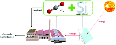 | ||
| Fig. 1 Potential circular economy when CO2 is reduced by waste silicon from solar panels to produce alternative feedstock for industries. | ||
Ozin and coworkers17 successfully transformed CO2 to CO at a high initial rate of 4.5 mmol h−1 g−1 Si utilising hydride-terminated silicon nanoparticles at 150 °C and 27 psi (ca. 0.2 MPa) and under irradiation of 1 sun solar intensity. Dasog and coworkers18 synthesised methanol from CO2 (1 MPa) at 150 °C with a methanol yield of 0.23 mmol after 3 h using 0.25 g of hydride-terminated porous silicon nanoparticles. However, in both studies, the silicon powder had to be treated with a large amount of toxic hydrofluoric acid to synthesise the hydride-terminated silicon nanoparticles. Meanwhile, there has been no report on CO2 reduction using real silicon wafer waste from solar panel production.
In this study, we successfully synthesised formic acid, methanol, and formamide from CO2 and powdered silicon wafers obtained from a solar panel production process. This is the first report on catalytic CO2 reduction directly using silicon. A catalytic amount of fluoride salts significantly promoted the reaction under milder reaction conditions (0.1 MPa CO2 pressure, 95 °C). The sources of carbon and hydrogen in formic acid and methanol were confirmed by experiments using 13CO2 and D2O, respectively. The key catalytic reaction step is Si–Si bond cleavage and in situ formation of an active Si–H species, which was also revealed in the reaction of disilane and H2O with fluoride.19–21
Methods
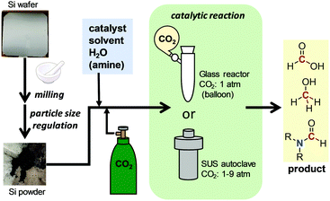
The methods for preparing powdered Si wafers and CO2 conversion reactions are summarised in Fig. 2. A silicon wafer used for solar panel production, Czochralski monocrystalline silicon wafer, was obtained from the Renewable Energy Research Center, AIST. It was crushed in an alumina mortar and sifted using an automatic sieve of 300, 90, 40, and 20 μm sizes. To a glass or stainless steel (SUS) autoclave reactor, the powdered wafer, catalyst, solvent, and H2O were added. Then, CO2 was introduced either by balloon or pressurisation, followed by heating to start the catalytic reaction.Results and discussion
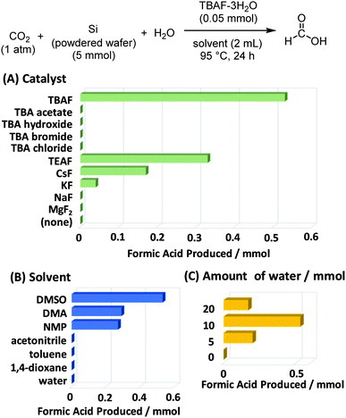
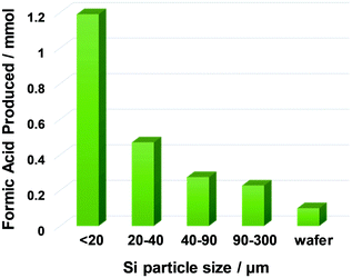
The first investigated reaction was the formation of formic acid. As shown in Fig. 3, the effects of catalyst (A), solvent (B), and water additive (C) were screened. Fluoride was found to be the best anion to catalyse this reaction, due to its ability to break the Si–Si bonds in metallic silicon. In the presence of tetrabutylammonium fluoride (TBAF), the amount of formic acid formed was the highest. Tetrabutylammonium (TBA) salts with other anions did not show any catalytic activity. No product was obtained without TBAF catalyst. We also confirmed that no reaction occurred without silicon powder. In terms of solvents, polar aprotic solvents such as dimethylsulfoxide (DMSO), dimethylacetamide (DMA), and N-methylpyrrolidone (NMP) were suitable for the reaction, while the less polar ones (toluene and dioxane) performed significantly worse. The reaction was also carried with and without added H2O. Formic acid production was not observed in the absence of H2O, and it reached the optimum value when using 10 mmol of H2O. However, excess H2O had a detrimental effect on the formic acid yield, probably because of the enhanced solvation effect of TBAF-3H2O, which reduced the activity of fluoride anion as a catalyst.The effect of silicon particle size was also examined. Fig. 4 shows that the finest powder yielded the most formic acid, which is significantly different from the coarse silicon powders and the parent silicon wafer. Note that Ozin et al.17 utilised silicon nanoparticles with an average diameter of 3.5 nm, and Dasog et al.18 utilised porous silicon nanoparticles with a diameter of 155 ± 25 nm. In contrast, the silicon wafers used in this study were only mechanically crushed without any chemical treatment, but they afforded a large amount of formic acid (up to 1.2 mmol) with a catalytic amount of the fluoride source (0.05 mmol). We also examined the reaction using commercially available silicon powder. Under similar conditions using TBAF catalyst, the yield of formic acid was 0.10 mmol,12 which is much lower than the results reported here. This is due to the particle size differences and/or freshness of silicon particle surface.
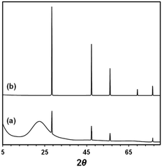
The effect of silicon particle size was also apparent from the X-ray photoelectron spectroscopy (XPS) analysis of residual silicon powder after formic acid synthesis, as shown in Table 1 and Fig. S1 (ESI†). Crushing the silicon wafer increased the percentage of exposed Si0 (binding energy, BE: 99.4 eV) on the particle surface, guaranteeing easy access for fluoride anions to break the Si–Si bonds and a high yield of hydrosilane. While most of the Si0 was oxidised to Si4+ (SiO2, BE: 103.5 eV) after the reaction, some Si0 remained in the silicon wafer without crash, probably because of the inaccessibility of the inner parts of the wafer to the reagents and catalyst. The fresh silicon powder and recovered solid after the reaction were characterized by XRD and SEM-EDS. As shown in Fig. 5, XRD analysis indicates that clear signals assigned to metallic silicon was observed in fresh powder, while this intensity decreased with increasing a board signal at ∼20 degree. This broad signal is assigned to amorphous SiO2. SEM-EDS analysis also revealed that the significant amount of oxygen atom was detected in recovered samples, which was scarcely observed in fresh silicon powder (Fig. S6, ESI†). These results indicate that silicon powder was oxidized by the reduction of CO2.
| Silicon source | Condition | Si4+ (%) | Si0 (%) |
|---|---|---|---|
| Si wafer | Fresh | 44 | 56 |
| After catalysis | 91 | 9 | |
| Powdered Si wafer (diameter < 40 μm) | Fresh | 24 | 76 |
| After catalysis | 99 | 1 |
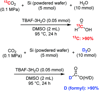
We have previously reported a reaction mechanism for CO2 reduction by disilane (R3Si–SiR3) with H2O and fluoride catalysts, including Si–Si bond cleavage and the in situ formation of an active Si–H species that reduces CO2. The applicability of that mechanism to the current reaction system with metallic silicon was examined using isotope experiments, as summarised in Scheme 1. The main goal was to determine whether the formic acid was derived from CO2 and H2O. First, fluoride-catalysed synthesis of formic acid was conducted using an excess amount of 13C-enriched CO2 (99 atom% 13C) in a balloon at atmospheric pressure to confirm the source of carbon. The 1H NMR spectrum of the reaction mixture (Fig. S2, ESI†) indicates the coupling of 13C–1H through a split of the formyl peak around 8 ppm with J1H–13C = 215 Hz.20,23 A similar experiment of formic acid synthesis was performed using 10 mmol of D2O (>99.8 atom% D) instead of H2O in typical experiments, in order to confirm the source of proton. After 24 h, the reaction mixture was examined using 2H NMR, where the formic acid-d showed a clear peak at 7.82 ppm (Fig. S3, ESI†). Mass analysis also revealed that deuterium was incorporated into the formyl group of the synthesised formic acid (Fig. S4, ESI†).
To increase the conversion of CO2, we further optimised the reactor and CO2 pressure, as shown in Table 2. The use of an SUS autoclave reactor with a volume of 27 mL and atmospheric pressure of CO2 significantly increased the yield of formic acid to 68% (based on CO2). Meanwhile, the amount of formic acid increased continuously with increasing CO2 pressure.
| Reactor | CO2b (atm) | Formic acidc (mmol) | Yield of formic acid based on CO2d (%) |
|---|---|---|---|
| a Reaction conditions: powdered silicon wafer (5 mmol; diameter < 20 μm), CO2, H2O (10 mmol), catalyst (0.85 mmol), DMSO (2 mL), 95 °C, 24 h. b Initial pressure during CO2 introduction. c Yield was determined using the internal standard technique of 1H NMR with CDCl3 as the solvent and 1,3,5-triisopropylbenzene as the internal standard. d Yield was calculated based on the amount of CO2 used. | |||
| Glass (balloon) | 1.0 (excess) | 0.55 | — |
| Autoclave | 1.0 | 0.82 | 68 |
| Autoclave | 3.0 | 1.03 | 28 |
| Autoclave | 5.0 | 1.05 | 17 |
| Autoclave | 9.2 | 1.75 | 16 |
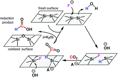
To understand the mechanism of CO2 reduction reaction with the powdered silicon wafer, F 1s XPS spectra were measured for the silicon wafer and the catalyst as shown in Fig. S5 (ESI†). After the reaction, silicon bonded with one or two fluorine atoms. The formation of Si–H on the silicon surface in the presence of fluoride and H2O is widely accepted.17,18 The isotopic experimental results in Scheme 1 indicate that CO2 and H2O are converted to formic acid. Considering these findings, we propose a reaction mechanism (Scheme 2) for the fluoride-catalysed reduction of CO2 by metallic silicon and H2O. Initially, fluoride anions attack and cleave Si–Si bonds near the surface. A new Si–F bond is formed in the silicon that is more electron-deficient, and the other silicon atom forms a new Si–H bond with nearby water molecule. The newly formed Si–H bond reduces CO2 with the help of an anionic catalyst (A−: fluoride or hydroxide) according to a previously reported mechanism.22 The resulting surface-bonded silylformate then undergoes hydrolysis to yield formic acid and an oxidised surface. Because of the high oxophilicity of silicon atoms, some of the Si–F is replaced by silanols (Si–OH) or siloxane (Si–O–Si), and a free fluoride anion is regenerated. However, the replacement of fluorosilane with silanol may not be irreversible but rather follows an equilibrium.20 This reaction mechanism is based on the reaction between CO2, H2O, and disilane (R3Si–SiR3).22
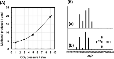
The TBA-catalysed reaction system using the powdered silicon is potentially applicable to produce other reduction products from CO2. During the isotopic experiments investigating the carbon and hydrogen sources of formic acid (Scheme 1), we observed methanol, a six-electron reduction product of CO2, in our reaction mixture. The methanol yield increased with increasing CO2 pressure (Fig. 6A). In addition, this methanol contains a considerable amount of 13C (Fig. 6B), meaning that it originates from CO2 by reduction with hydride from H2O. Further optimisation of the reaction conditions may increase the methanol yield.
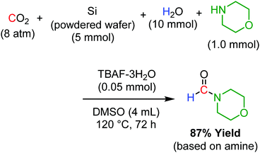
Another important application of our powdered silicon-TBAF catalytic system is the reductive functionalisation of CO2. In the presence of morpholine, both CO2 reduction and C–N bond formation proceeded to produce N-formyl morpholine with a 87% yield (Scheme 3). Isotopic experiments using 13CO2 and D2O indicated that the formyl group of the product was derived from CO2 and H2O. No formylation product was obtained in the absence of powdered Si. The use of hydrosilane or molecular hydrogen for reductive functionalisation is well known.23 However, this is the first report on reductive functionalisation using powdered Si wafer, a waste material, as the reducing agent.
Conclusions
We have shown that metallic silicon waste recovered from the solar panel production process can be utilised as a reducing agent for CO2 to produce formic acid, methanol, and formamide. We demonstrated that fluoride compounds such as TBAF act as efficient catalysts for the reductive transformation of CO2, with up to 68% yield of formic acid. Isotopic experiments and XPS analysis of silicon before and after the catalytic reaction revealed that the fluoride-silicon interaction induced the in situ formation of Si–H species, which in turn reduced CO2. This is the first report of a catalytic CO2 reduction process that directly uses waste metallic silicon. This methodology has the potential to achieve the dual goals of recycling CO2 as a chemical feedstock and utilising silicon waste from solar panels to produce energy storage materials.Author contributions
K. M. and R. A. P. conceived and supervised the project. K. N. and C. N. conducted most of the experiments and analysed the data. R. W. performed the formamide synthesis experiments. T. M. and H. T. prepared metallic Si. Y. M. conceived the catalytic CO2 conversion mechanism and supervised its study. R. A. P. and K. M. wrote the manuscript.Conflicts of interest
There are no conflicts to declare.Acknowledgements
Part of this study was supported by the JSPS Grant-in-Aid for Scientific Research on Innovative Areas (grant no. JP20H04804) and Transformative Research Areas (grant no. JP21H05099), the Noguchi Institute, and the Yazaki Memorial Foundation for Science and Technology.Notes and references
- The Meteorological Office, UK, “Mauna Loa carbon dioxide forecast for 2021,” can be found under https://www.metoffice.gov.uk/research/climate/seasonal-to-decadal/long-range/forecasts/co2-forecast.
- C. M. Meure, D. Etheridge, C. Trudinger, P. Steele, R. Langenfelds, T. van Ommen, A. Smith and J. Elkins, Geophys. Res. Lett., 2006, 33, L14810 CrossRef.
- NOAA National Centers for Environmental Information, State of the Climate: Global Climate Report for Annual 2020, NOAA National Centers For Environmental Information, 2021.
- J. Tollefson, Nature, 2021, 589, 343 CrossRef CAS PubMed.
- Z. Liu, P. Ciais, Z. Deng, R. Lei, S. J. Davis, S. Feng, B. Zheng, D. Cui, X. Dou, B. Zhu, R. Guo, P. Ke, T. Sun, C. Lu, P. He, Y. Wang, X. Yue, Y. Wang, Y. Lei, H. Zhou, Z. Cai, Y. Wu, R. Guo, T. Han, J. Xue, O. Boucher, E. Boucher, F. Chevallier, K. Tanaka, Y. Wei, H. Zhong, C. Kang, N. Zhang, B. Chen, F. Xi, M. Liu, F.-M. Bréon, Y. Lu, Q. Zhang, D. Guan, P. Gong, D. M. Kammen, K. He and H. J. Schellnhuber, Nat. Commun., 2020, 11, 5172 CrossRef CAS PubMed.
- United Nations Environment Programme, “Emissions Gap Report 2020,” can be found under https://www.unenvironment.org/emissions-gap-report-2020, 2020.
- United Nations Environment Programme, Emissions Gap Report 2019, Nairobi, Kenya, 2019.
- International Energy Agency, “Data & Statistics,” can be found under https://www.iea.org/data-and-statistics, n.d.
- International Energy Agency, Renewables 2020: Analysis and Forecast to 2025, International Energy Agency, 2020.
- M. Aresta, Carbon Dioxide as Chemical Feedstock, John Wiley & Sons, Ltd, 2010, pp. 1–13 Search PubMed.
- W.-H. Wang, X. Feng and M. Bao, in Transformation of Carbon Dioxide to Formic Acid and Methanol, ed. W.-H. Wang, X. Feng and M. Bao, Springer, Singapore, 2018, pp. 1–6 Search PubMed.
- T. Sakakura, J.-C. Choi and H. Yasuda, Chem. Rev., 2007, 107, 2365–2387 CrossRef CAS PubMed.
- P. De Luna, C. Hahn, D. Higgins, S. A. Jaffer, T. F. Jaramillo and E. H. Sargent, Science, 2019, 364, 350 CrossRef PubMed.
- S. Weckend, A. Wade and G. A. Heath, End of Life Management: Solar Photovoltaic Panels, IRENA And IEA-PVPS, 2016 Search PubMed.
- O. Tomioka, “Japan tries to chip away at mountain of disused solar panels – Nikkei Asian Review,” can be found under https://asia.nikkei.com/Business/Technology/Japan-tries-to-chip-away-at-mountain-of-disused-solar-panels, 2016.
- Study group on reuse, recycling, and proper disposal of used renewable energy equipment, Report on reuse, recycling, and proper disposal of solar power generation equipments, Japan's Ministry Of The Environment, 2016.
- W. Sun, C. Qian, L. He, K. K. Ghuman, A. P.-Y. Wong, J. Jia, A. A. Jelle, P. G. O’Brien, L. M. Reyes, T. E. Wood, A. S. Helmy, C. A. Mims, C. V. Singh and G. A. Ozin, Nat. Commun., 2016, 7, 12553 CrossRef CAS PubMed.
- M. Dasog, S. Kraus, R. Sinelnikov, J. G.-C. Veinot and B. Rieger, Chem. Commun., 2017, 53, 3114–3117 RSC.
- K. Motokura, M. Naijo, S. Yamaguchi, A. Miyaji and T. Baba, Chem. Lett., 2015, 44, 1464–1466 CrossRef CAS.
- K. Motokura, M. Naijo, S. Yamaguchi, A. Miyaji and T. Baba, Chin. J. Catal., 2017, 38, 434–439 CrossRef CAS.
- K. Motokura and R. A. Pramudita, Chem. Rec., 2019, 19, 1199–1209 CrossRef CAS PubMed.
- K. Motokura, M. Naijo, S. Yamaguchi, A. Miyaji and T. Baba, Chem. Lett., 2015, 44, 1217–1219 CrossRef CAS.
- Q. Liu, L. Wu, R. Jackstell and M. Beller, Nat. Commun., 2015, 6, 1–15 Search PubMed; G. Fiorani, W. Guo and A. W. Kleij, Green Chem., 2015, 17, 1375–1389 RSC; X.-F. Liu, R. Ma, C. Qiao, H. Cao and L.-N. He, Chem. – Eur. J., 2016, 22, 16489–16493 CrossRef CAS PubMed; F. D. Bobbink, S. Das and P. J. Dyson, Nat. Protoc., 2017, 12, 417–428 CrossRef PubMed; X.-Y. Li, S.-S. Zheng, X.-F. Liu, Z.-W. Yang, T.-Y. Tan, A. Yu and L.-N. He, ACS Sustainable Chem. Eng., 2018, 6, 8130–8135 CrossRef; R. A. Pramudita and K. Motokura, Green Chem., 2018, 20, 4834–4843 RSC; R. A. Pramudita and K. Motokura, ChemSusChem, 2021, 14, 281–292 CrossRef PubMed.
Footnote |
| † Electronic supplementary information (ESI) available: Experimental details, XPS spectra, and product data for isotopic experiments. See DOI: https://doi.org/10.1039/d1ya00077b |
| This journal is © The Royal Society of Chemistry 2022 |

