A gold(III)–TADF emitter as a sensitizer for high-color-purity and efficient deep-blue solution-processed OLEDs†
Dongling
Zhou
a,
Siping
Wu
a,
Gang
Cheng
 *abc and
Chi-Ming
Che
 *abc
*abc
aState Key Laboratory of Synthetic Chemistry, Department of Chemistry, The University of Hong Kong, Pokfulam Road, Hong Kong SAR, China. E-mail: ggcheng@hku.hk; cmche@hku.hk
bHong Kong Quantum AI Lab Limited, 17 Science Park West Avenue, Pak Shek Kok, Hong Kong SAR
cHKU Shenzhen Institute of Research and Innovation, Shenzhen 518053, China
First published on 1st February 2022
Abstract
Herein is described a blue-emitting gold(III)–TADF complex Au-1 that could act as a sensitizer for a solution-processed organic light-emitting diode (SP-OLED), in which a multi-resonance TADF emitter ν-DABNA is employed as the emissive dopant. Photophysical investigations revealed an efficient energy transfer (ET) process in the sensitized system with estimated Förster distance of 2.83 nm and ET rate of 2.35 × 10⁷ s−1. The fabricated blue SP-OLEDs attained high maximum external quantum efficiency of up to 16.6%, high color purity with a full-width at half maximum of 23 nm and Commission Internationale de L’Éclairage coordinates of (0.14, 0.18). A slight efficiency roll-off of 13% was observed for the Au-1 sensitized ν-DABNA-based device, which is much improved relative to that (30%) of the Au-1-based device, attributed to the effective ET process from Au-1 to ν-DABNA that could suppress the accumulation of triplet excitons on Au-1 at high luminance.
Introduction
Blue light-emitting materials are indispensable in the development of organic light-emitting diodes (OLEDs) for display and lighting applications.1–4 However, compared to green and red ones, the development of blue-emitting materials simultaneously possessing high efficiency and color purity is lagging behind, particularly for low-cost solution-processed OLEDs (SP-OLEDs) that require emissive dopants to be highly soluble in common solvents.5–16 Wang, Shao, and co-workers recently developed through-space charge transfer polymers containing face-to-face aligned donors and acceptors for achieving efficient blue thermally activated delayed fluorescence (TADF) emission.6 The SP-OLEDs made with these polymers exhibited high maximum external quantum efficiency (EQEmax) of 18.8%. Nonetheless, the emission color was sky blue with Commission Internationale de LÉclairage (CIE) coordinates of (0.20, 0.31). Another blue SP-OLED employing a tris-triazolotriazine-based TADF emitter as an emissive dopant reported by Lee, Zhu, Wang, and co-workers gave EQEmax of 23.23% and sky-blue emission with CIE coordinates of (0.19, 0.36).7 However, a severe efficiency roll-off of the device was observed with EQE at a luminance of 1000 cd m−2 (EQE1000) of about 6%. Cho, Choi, and co-workers demonstrated three deep-blue to sky-blue TADF emitters bearing organoboron-based cores as acceptors and carbazole derivatives as donors.9 A deep-blue SP-OLED made with one of these boron-based emitters showed EL at 424 nm with CIE coordinates of (0.17, 0.07), together with a narrow spectrum with a full-width at half maximum (FWHM) of 42 nm. Despite a decent EQEmax of 9.90% achieved for this device, the EQE1000 reduced to less than 1%. Continuous efforts have been devoted to this boron-based TADF system by the same group. These workers reported another ultra-deep-blue SP-OLED with improved EQEmax of 15.8% and CIE coordinates of (0.16, 0.05) relative to their previous results.12Despite considerable efforts made to improve the performance of blue SP-OLEDs, the reported device performance data, particularly EQE and color purity, remain inferior to those of blue OLEDs manufactured using a vacuum deposition technique, especially for those with multi-resonance TADF compounds as emissive dopants.17–25 In 2016, Hatakeyama and co-workers reported a rigid polycyclic framework consisting of nitrogen and boron atoms positioned oppositely and first proposed a concept of multi-resonance TADF.19 Since then, many high-performance multi-resonance TADF emitters with extremely narrow emission bandwidths and relatively large oscillator strength of radiative transition have been developed. A solution-processable multi-resonance TADF material (OAB-ABP-1) with an extended π-skeleton and bulky substituents was designed and utilized in the fabrication of SP-OLEDs.26 A high EQEmax of 21.8% and EQE1000 of 17.4% were achieved with the as fabricated pure green SP-OLEDs that showed CIE coordinates of (0.12, 0.63) and a narrow electroluminescent (EL) spectrum with a FWHM of 33 nm. Nonetheless, the examples of blue SP-OLEDs fabricated with multi-resonance TADF emitters are scarce,15,27 and one of the related studies reported that the performance of SP-OLEDs was far inferior to that of vacuum-deposited OLEDs based on the same dopant probably attributable to the unsatisfactory film quality by the spin-coating method.15 Multi-resonance TADF compounds usually show poor solubility as a result of their high molecular rigidity and planarity.
Phosphorescence- or TADF-sensitized fluorescence (PSF or TASF, depending on the emission mechanism of the sensitizer) is a cascade energy transfer (ET) process in which the excited state energy is transferred from the host to the fluorescent dopant via a phosphorescent or TADF sensitizer.28–33 Such PSF/TASF OLEDs take advantage of both phosphorescence/TADF sensitizers and fluorescent emitters, exhibiting the high efficiency of phosphorescence/TADF, and the high color purity and long operational lifetime of fluorescence, and therefore are regarded as generation-3.5 OLEDs.34 Recent studies demonstrated that multi-resonance TADF emitters could replace conventional fluorescent dopants to attain high-performance blue-emitting PSF/TASF OLEDs fabricated by vacuum deposition.35–39 Enlightened by these recent advances, the obstacles of poor solubility of multi-resonance TADF emitters and inefficient ET from the hosts to multi-resonance TADF emitters, which hamper the development of blue SP-OLEDs, could be overcome by incorporating TADF sensitizers in the emitting layers (EMLs) to develop TASF devices.
In the present study, we demonstrated a deep-blue SP-OLED by utilizing a blue-emitting gold(III)–TADF complex Au-1 as the sensitizer. This gold(III) complex showed a high emission quantum yield of 82% in a thin film and high-energy electroluminescence with λmax at 470 nm.8 A multi-resonance TADF emitter ν-DABNA was selected as a guest molecule as it was reported to show excellent performance in vacuum-deposited OLEDs in which a high EQEmax of 34.4%, deep blue electroluminescence with CIE coordinates of (0.12, 0.11) and narrowband emission (FWHM = 18![[thin space (1/6-em)]](https://www.rsc.org/images/entities/char_2009.gif) nm) were achieved.20 To realize an efficient TASF OLED, effective ET from the host to Au-1 and then to ν-DABNA are crucial. Efficient ET from the host 2,6-bis(9H-carbazol-9-yl)pyridine (PYD2) to Au-1 has been observed in our previous work,8 and the ET from Au-1 to ν-DABNA is the subject of investigation in this work.
nm) were achieved.20 To realize an efficient TASF OLED, effective ET from the host to Au-1 and then to ν-DABNA are crucial. Efficient ET from the host 2,6-bis(9H-carbazol-9-yl)pyridine (PYD2) to Au-1 has been observed in our previous work,8 and the ET from Au-1 to ν-DABNA is the subject of investigation in this work.
Results and discussion
Energy transfer from Au-1 to ν-DABNA
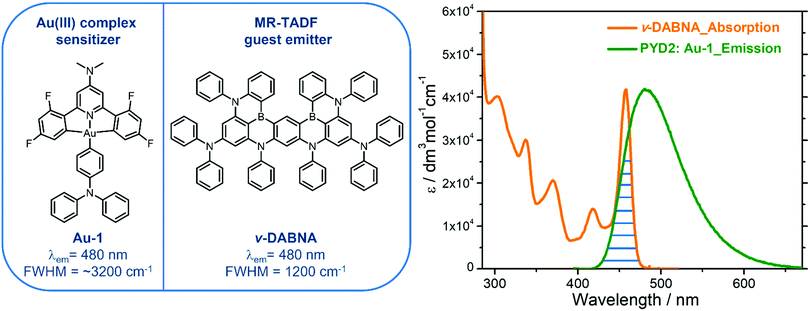
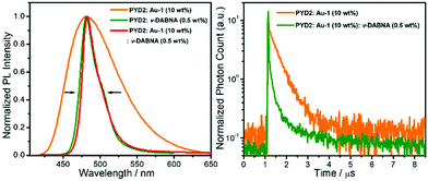
With an aim to investigate the ET process in the Au-1:ν-DABNA sensitized system, the absorption spectrum of ν-DABNA and emission spectrum of the sensitizer Au-1 were measured. As portrayed in Fig. 1, there is a decent spectral overlap between the emission of Au-1 and the absorption of ν-DABNA, suggesting that an effective ET from Au-1 to ν-DABNA could occur. The ET process of the sensitized system was further examined in PYD2 thin films. After doping with ν-DABNA, the emission lifetimes of the Au-1:ν-DABNA sensitized system significantly decreased relative to that of Au-1 only and there is no residual emission from the sensitizer Au-1, as shown in Fig. 2. These observations altogether suggest effective ET in this sensitized system upon photo-excitation.Given the low dopant concentration of the guest emitter ν-DABNA (0.5 wt%), short-range Dexter ET can be ignored in which all guest molecules should be located adjacent to a host molecule, and Förster resonance energy transfer (FRET) is therefore considered as the dominant ET process in our sensitized system. The Förster distance (R0) is commonly utilized to evaluate the efficiency of a FRET process and can be expressed by the following eqn (1):40,41
 | (1) |
 | (2) |
 | (3) |
 | (4) |
 | (5) |
 | (6) |
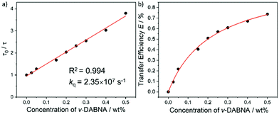
As portrayed in Fig. 3b, the transfer efficiency E reaches 50% at a concentration of 0.196 wt%. Assuming that this concentration corresponds to an average of one acceptor molecule in a sphere of radius R0 and an average film density of 1 g cm−3, R0 was estimated to be 2.83 nm,44 comparable to the value calculated based on eqn (1).
Film surface morphology
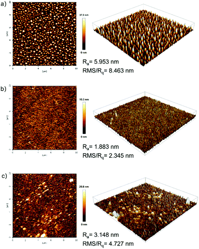
The film-forming ability and film morphology of solution-processed films prepared with PYD2:v-DABNA(2 wt%), PYD2:Au-1(10 wt%):v-DABNA(0.5 wt%) and PYD2:Au-1(10 wt%):v-DABNA(2 wt%) were investigated by atomic force microscopy (AFM) in tapping mode. As observed from the AFM images in Fig. 4, the average roughness (Ra)/root mean square (RMS) roughness (Rq) values were found to be 5.953 nm/8.463 nm for the sample PYD2:v-DABNA(2 wt%), 1.883 nm/2.345 nm for the sample PYD2:Au-1(10 wt%):v-DABNA(0.5 wt%) and 3.148 nm/4.727 nm for the sample PYD2:Au-1(10 wt%):v-DABNA(2 wt%), respectively. In comparison to the film made with only v-DABNA (2 wt%), the sample of PYD2:Au-1(10 wt%):v-DABNA(2 wt%) showed much smaller RMS value, suggestive of the improved film quality after incorporating Au-1. Apparently, the film made with PYD2:Au-1(10 wt%):v-DABNA(0.5 wt%) displayed a smoother and more uniform profile than the sensitized system with 2 wt% v-DABNA, having smaller Ra and RMS values, suggesting better film-forming capability.This can be attributed to the good compatibility between PYD2, Au-1 and v-DABNA at their respective concentrations used. These results verify that our sensitized systems possess high compatibility and morphological stabilities, accounting for our promising solution-processed OLEDs based on the sensitized system under the optimized conditions used.
Device characteristics of blue-emitting SP-OLEDs
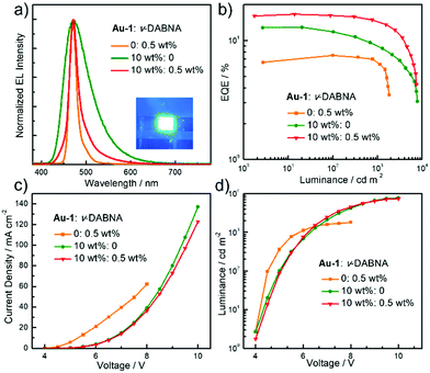
TASF SP-OLEDs were fabricated by adopting Au-1 as a TADF sensitizer and ν-DABNA as a deep-blue emissive dopant. As shown in Fig. 5, the device architecture was ITO/PEDOT:PSS/PYD2:Au-1:v-DABNA (50 nm)/DPEPO (10 nm)/TPBi (40 nm)/LiF (1.2 nm)/Al (100 nm), in which PYD2 was utilized as the host material in the EML. Bis[2-(diphenylphosphino)phenyl]ether oxide (DPEPO) and 1,3,5-tris(1-phenyl-1H-benzo[d]imidazol-2-yl)benzene (TPBi) function as hole/exciton blocking and electron transporting materials, respectively. Au-1 and ν-DABNA were co-doped in the PYD2 host in the EML with different concentrations. As depicted in Fig. 6a, the EL spectrum of the device with 10 wt% Au-1 and 0.5 wt% ν-DABNA is much narrower than that of the device with 10 wt% Au-1 only and slightly broader than that of the device with 0.5 wt% ν-DABNA only, suggesting an efficient ET from Au-1 to ν-DABNA. However, when compared with the corresponding emission spectra shown in Fig. 2 in which the emission of the Au-1:ν-DABNA sensitized system and ν-DABNA only are almost identical, the ET from Au-1 to ν-DABNA shown in the EL spectrum is slightly incomplete, presumably due to the different excitation processes of electroluminescence and photoluminescence. In the photoluminescence measurements, PYD2 is first excited by light at a wavelength of 330 nm. It then transfers the excited state energy to ν-DABNA by a cascade ET viaAu-1. On the other hand, in the TASF SP-OLED, direct charge trapping on both Au-1 and ν-DABNA molecules may play a main role in exciton formation. Fig. 5 shows that both the LUMO and HOMO levels of Au-1 and ν-DABNA are within those of PYD2, suggesting the possibility of trapping both holes and electrons on Au-1 and ν-DABNA molecules. The trapping effect is supported by the current density–voltage characteristics shown in Fig. 6c and Fig. S1c (ESI†), in which the current density decreased with increasing dopant concentration at a certain driving voltage. The trapping effect may influence the cascade ET, leading to a slightly incomplete ET from Au-1 to ν-DABNA, as shown in Fig. 6a. When ν-DABNA was utilized as the emissive dopant alone, the EL spectrum with a narrow FWHM of 18 nm remained almost unchanged upon increasing the doping concentration of ν-DABNA from 0.5 to 2 wt% (Fig. S2a, ESI†). The EQEmax of the ν-DABNA-based device was 7.51% at a low dopant concentration of 0.5 wt%, increased to 8.60% at a higher concentration of 1 wt% and then decreased to 7.30% at an even higher concentration of 2 wt%. The relatively lower EQEmax at a low concentration of 0.5 wt% might be due to incomplete ET from the host PYD2, whose emission can be observed in the enlarged EL spectrum shown in Fig. S2c (ESI†). A decrease in the EQEmax of the device at a higher concentration of ν-DABNA (2 wt%) might be attributable to concentration quenching.17 As depicted in Fig. S1a (ESI†), the EL spectra became narrower with increasing concentration ratios of ν-DABNA to Au-1 in the sensitized devices because of the trapping effects of both ν-DABNA and Au-1. In the device with a higher concentration ratio of ν-DABNA to Au-1, more excitons directly formed on the ν-DABNA molecules. Since the EL spectrum of the sensitized device is the combined emission from both ν-DABNA and Au-1, more exciton formation and recombination on ν-DABNA would cause more ν-DABNA portion in the observed EL emission, resulting in a narrower EL spectrum. As depicted in Fig. 6b and Fig. S1b (ESI†), the TASF OLED with 10 wt% Au-1 and 0.5 wt% ν-DABNA showed an EQEmax as high as 16.6%. Although direct charge trapping is the primary mechanism of exciton formation in the TASF devices, the efficient ET from Au-1 to ν-DABNA resulted in an extremely narrow EL spectrum with a FWHM of 23 nm and CIE coordinates of (0.14, 0.18) in the sensitized device made with 0.5 wt% ν-DABNA and 10 wt% Au-1 (Fig. 6a). Therefore, different from the incomplete ET from the host PYD2 to ν-DABNA in the ν-DABNA-based device with a low dopant concentration of 0.5% (Fig. S2, ESI†), by cascade ET, all excitons formed on the host PYD2 were transferred to ν-DABNA viaAu-1 in the TASF device, leading to a highly improved EQEmax. The EQEmax of the sensitized device (16.6%) is higher than that of the Au-1-based device (12.9%), probably because the sensitized system is capable of recycling the triplet excitons quenched by the host.38 In addition, the efficient FRET process of the sensitized system could suppress the accumulation of triplet excitons on the sensitizer, leading to alleviated efficiency roll-offs. As shown in Fig. 6b, an EQE1000 of 14.4% was achieved in the best-sensitized device, corresponding to an efficiency roll-off of 13%, which is much improved relative to that (30%) of the Au-1-based device. With the increased concentration of ν-DABNA, the EQEmax of the sensitized devices decreased (Table S2, ESI†). This might be due to the concentration quenching of ν-DABNA. Additionally, in comparison to the sensitized system of PYD2:Au-1(10 wt%):v-DABNA(0.5 wt%), the system of PYD2:Au-1(10 wt%):v-DABNA(2 wt%) showed poor film-forming ability, as aforementioned, together resulting in a lower EQEmax. The efficiency of the TASF device with 10 wt% Au-1 and 0.5 wt% ν-DABNA is among the best of the reported blue-emitting SP-OLEDs, particularly those with CIEy less than 0.2, as shown in Fig. 7.5,9,11,12,14,15 The preliminary lifetime of the device with 10 wt% Au-1 and 0.5 wt% ν-DABNA was measured under our laboratory conditions. As shown in Fig. S3 (ESI†), the operational lifetime at 50% of the initial luminance of 1000 cd m−2 (LT50) was 16 min. Similar results have been reported for blue SP-OLEDs with similar device structures,7,10 and the relatively short lifetime could be attributed to a lack of device optimization and the harmful effect of PEDOT:PSS.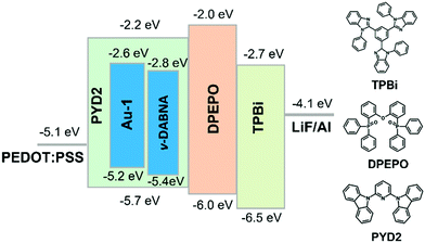 | ||
| Fig. 5 Schematic device structure with proposed energy level diagrams and chemical structures of supportive organic materials. | ||
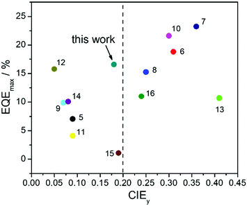 | ||
| Fig. 7 Summary of EQEmax and CIEy values of recently reported SP-OLEDs. The reference numbers are presented next to the relevant data points. | ||
Conclusions
In summary, a high EQEmax of 16.6%, high color purity with a FWHM of 23 nm and CIE coordinates of (0.14, 0.18) were simultaneously actualized in an optimized TASF SP-OLED by employing Au-1 as a TADF sensitizer and ν-DABNA as a deep-blue emitter. Owing to the efficient cascade ET from PYD2 to ν-DABNA viaAu-1 and the recycling of triplet excitons that were wasted in the Au-1-based TADF devices of the TASF system, the EQEmax of the TASF device was found to be higher than those of both the Au-1- and ν-DABNA-based ones. A severe efficiency roll-off of 30% was found for the Au-1-based device because of accumulation of triplet excitons on Au-1 at high brightness. By incorporating 0.5 wt% ν-DABNA, the efficiency roll-offs in the sensitized device were significantly reduced down to 13%, attributable to the suppressed accumulation of triplet excitons on Au-1 at high luminance due to efficient ET in the TASF device.Experimental section
Materials
PYD2, DPEPO, TPBi, ν-DABNA and LiF were purchased from Luminescence Technology Corp; PEDOT: PSS was purchased from Heraeus. All of these materials were used as received. Au-1 was synthesized based on the reported method.8Measurements
The procedure for the preparation of thin-film samples for kinetic studies is described as follows: the mixture of PYD2 and dopant(s) in chlorobenzene (10 mg mL−1) was spin coated on quartz films at a speed of 500 rpm inside a glove box and transparent film samples were obtained after being annealed at 70 °C for 20 minutes. The emission lifetimes were recorded at 450 nm and the data points after the prompt fluorescence signal stemming from v-DABNA were considered to be the emission decay of Au-1 and fitted by using the equation of . The procedure for the preparation of thin-film samples for AFM measurement is described as follows: the mixture of PYD2 and dopant(s) in chlorobenzene (10 mg mL−1) was spin coated on quartz slides at a speed of 3000 rpm inside a glove box and the transparent thin films were obtained after being annealed at 70 °C for 20 minutes. The prepared films were examined by atomic force microscopy (AFM) in tapping mode (a Bruker Nano Wizard ULTRA Speed 2 instrument). Emission quantum yields of these thin-film samples were measured using a Hamamatsu C11347 Quantaurus-QY Absolute PL quantum yields measurement system. The emission lifetime measurements were performed on an LP920-KS Laser Flash Photolysis spectrophotometer (Edinburgh Instrument Ltd) equipped with a Q-switched Nd:YAG laser. Emission spectra of these thin-film samples were recorded on a Horiba Fluorolog-3 spectrophotometer.
Device fabrication and characterization
An aqueous solution of PEDOT:PSS was spin-coated onto a cleaned ITO coated glass substrate and baked at 120 °C for 20 minutes to remove the residual water solvent inside a clean room. The mixture of PYD2 and emitting dopant(s) in chlorobenzene was spin-coated atop the PEDOT:PSS layer inside a glove box. After being annealed at 70 °C for 30 minutes, all devices were subsequently transferred into a Kurt J. Lesker SPECTROS vacuum deposition system without exposure to air. In the vacuum chamber, organic materials of DPEPO and TPBi were thermally deposited in sequence at a rate of ∼0.1 nm s−1. Finally, LiF (1.2 nm) and Al (100 nm) were thermally deposited at rates of 0.03 and 0.2 nm s−1, respectively.EL spectra, CIE coordinates, luminance-current–voltage characteristics, current efficiency, power efficiency, and EQE were measured using a Keithley 2400 source-meter and an absolute external quantum efficiency measurement system (C9920-12, Hamamatsu Photonics). All devices were characterized at room temperature under an ambient air environment without encapsulation. The operational lifetimes of the devices were measured in a glove box with both concentrations of O2 and H2O lower than 1 ppm. The efficiency roll-offs were evaluated based on the formula of [(EQEmax − EQE1000)/EQEmax] × 100 in which the EQEmax and EQE1000 refer to maximum EQE and EQE at a luminance of 1000 cd m−2, respectively.
Conflicts of interest
There are no conflicts of interest to declare.Acknowledgements
This research was funded by the Major Program of Guangdong Basic and Applied Research (2019B030302009), the Basic Research Program of Shenzhen (JCYJ20170818141858021 and JCYJ20200109150414471), Shunde Science and Technology Bureau (2030218000158), Innovation and Technology Fund (PRP/071/19/FX) and Hong Kong Quantum AI Lab Limited.References
- Y. Im, S. Y. Byun, J. H. Kim, D. R. Lee, C. S. Oh, K. S. Yook and J. Y. Lee, Adv. Funct. Mater., 2017, 27, 1603007 CrossRef.
- J.-H. Lee, C.-H. Chen, P.-H. Lee, H.-Y. Lin, M.-K. Leung, T.-L. Chiu and C.-F. Lin, J. Mater. Chem. C, 2019, 7, 5874–5888 RSC.
- Z. Xu, B. Z. Tang, Y. Wang and D. Ma, J. Mater. Chem. C, 2020, 8, 2614–2642 RSC.
- M.-C. Tang, M.-Y. Chan and V. W.-W. Yam, Chem. Rev., 2021, 121, 7249–7279 CrossRef CAS PubMed.
- H. Usta, D. Alimli, R. Ozdemir, S. Dabak, Y. Zorlu, F. Alkan, E. Tekin and A. Can, ACS Appl. Mater. Interfaces, 2019, 11, 44474–44486 CrossRef CAS PubMed.
- Q. Li, J. Hu, J. Lv, X. Wang, S. Shao, L. Wang, X. Jing and F. Wang, Angew. Chem., Int. Ed., 2020, 59, 20174–20182 CrossRef CAS PubMed.
- X. Chen, S. Wang, H. L. Lee, J. Y. Lee, X. Liao, L. Li, W. Zhu and Y. Wang, Adv. Opt. Mater., 2021, 9, 2101518 CrossRef CAS.
- D. Zhou, G. Cheng, G. S. M. Tong and C.-M. Che, Chem. – Eur. J., 2020, 26, 15718–15726 CrossRef CAS PubMed.
- H. J. Kim, M. Godumala, S. K. Kim, J. Yoon, C. Y. Kim, H. Park, J. H. Kwon, M. J. Cho and D. H. Choi, Adv. Opt. Mater., 2020, 8, 1902175 CrossRef CAS.
- G. Kreiza, D. Berenis, D. Banevičius, S. Juršėnas, T. Javorskis, E. Orentas and K. Kazlauskas, Chem. Eng. J., 2021, 412, 128574 CrossRef CAS.
- P. Therdkatanyuphong, C. Kaiyasuan, P. Chasing, T. Kaewpuang, T. Chawanpunyawat, T. Sudyoadsuk and V. Promarak, ACS Appl. Electron. Mater., 2021, 3, 1311–1322 CrossRef CAS.
- H. J. Kim, H. Kang, J.-E. Jeong, S. H. Park, C. W. Koh, C. W. Kim, H. Y. Woo, M. J. Cho, S. Park and D. H. Choi, Adv. Funct. Mater., 2021, 31, 2102588 CrossRef CAS.
- J. Hwang, C. Y. Kim, H. Kang, J.-E. Jeong, H. Y. Woo, M. J. Cho, S. Park and D. H. Choi, J. Mater. Chem. C, 2020, 8, 16048–16056 RSC.
- J. Hwang, H. Kang, J.-E. Jeong, H. Y. Woo, M. J. Cho, S. Park and D. H. Choi, Chem. Eng. J., 2021, 416, 129185 CrossRef CAS.
- T. Xu, X. Liang and G. Xie, Front. Chem., 2021, 9, 691172 CrossRef CAS PubMed.
- Y. Chen, N. Li, Z. Huang, G. Xie and C. Yang, Chem. Eng. J., 2022, 430, 133078 CrossRef CAS.
- S. M. Suresh, D. Hall, D. Beljonne, Y. Olivier and E. Zysman-Colman, Adv. Funct. Mater., 2020, 30, 1908677 CrossRef.
- J.-M. Teng, Y.-F. Wang and C.-F. Chen, J. Mater. Chem. C, 2020, 8, 11340–11353 RSC.
- T. Hatakeyama, K. Shiren, K. Nakajima, S. Nomura, S. Nakatsuka, K. Kinoshita, J. Ni, Y. Ono and T. Ikuta, Adv. Mater., 2016, 28, 2777–2781 CrossRef CAS PubMed.
- Y. Kondo, K. Yoshiura, S. Kitera, H. Nishi, S. Oda, H. Gotoh, Y. Sasada, M. Yanai and T. Hatakeyama, Nat. Photonics, 2019, 13, 678–682 CrossRef CAS.
- D. Hall, S. M. Suresh, P. L. dos Santos, E. Duda, S. Bagnich, A. Pershin, P. Rajamalli, D. B. Cordes, A. M. Z. Slawin, D. Beljonne, A. Köhler, I. D. W. Samuel, Y. Olivier and E. Zysman-Colman, Adv. Opt. Mater., 2020, 8, 1901627 CrossRef CAS.
- M. Yang, I. S. Park and T. Yasuda, J. Am. Chem. Soc., 2020, 142, 19468–19472 CrossRef CAS PubMed.
- S. Oda, W. Kumano, T. Hama, R. Kawasumi, K. Yoshiura and T. Hatakeyama, Angew. Chem., Int. Ed., 2021, 60, 2882–2886 CrossRef CAS PubMed.
- J. Wei, C. Zhang, D. Zhang, Y. Zhang, Z. Liu, Z. Li, G. Yu and L. Duan, Angew. Chem., Int. Ed., 2021, 60, 12269–12273 CrossRef CAS PubMed.
- M. Nagata, H. Min, E. Watanabe, H. Fukumoto, Y. Mizuhata, N. Tokitoh, T. Agou and T. Yasuda, Angew. Chem., Int. Ed., 2021, 60, 20280–20285 CrossRef CAS PubMed.
- N. Ikeda, S. Oda, R. Matsumoto, M. Yoshioka, D. Fukushima, K. Yoshiura, N. Yasuda and T. Hatakeyama, Adv. Mater., 2020, 32, 2004072 CrossRef CAS PubMed.
- S. Xu, Q. Yang, Y. Zhang, H. Li, Q. Xue, G. Xie, M. Gu, J. Jin, L. Huang and R. Chen, Chin. Chem. Lett., 2021, 32, 1372–1376 CrossRef CAS.
- M. A. Baldo, M. E. Thompson and S. R. Forrest, Nature, 2000, 403, 750–753 CrossRef CAS PubMed.
- H. Nakanotani, T. Higuchi, T. Furukawa, K. Masui, K. Morimoto, M. Numata, H. Tanaka, Y. Sagara, T. Yasuda and C. Adachi, Nat. Commun., 2014, 5, 4016 CrossRef CAS PubMed.
- P.-K. Chow, G. Cheng, G. S. M. Tong, C. Ma, W.-M. Kwok, W.-H. Ang, C. Y.-S. Chung, C. Yang, F. Wang and C.-M. Che, Chem. Sci., 2016, 7, 6083–6098 RSC.
- S. Y. Byeon, D. R. Lee, K. S. Yook and J. Y. Lee, Adv. Mater., 2019, 31, 1803714 CrossRef PubMed.
- D. Zhang, X. Song, M. Cai and L. Duan, Adv. Mater., 2018, 30, 1705250 CrossRef PubMed.
- X. Song, D. Zhang, Y. Lu, C. Yin and L. Duan, Adv. Mater., 2019, 31, 1901923 CrossRef PubMed.
- X.-K. Chen, D. Kim and J.-L. Brédas, Acc. Chem. Res., 2018, 51, 2215–2224 CrossRef CAS PubMed.
- D. Zhang, X. Song, A. J. Gillett, B. H. Drummond, S. T. E. Jones, G. Li, H. He, M. Cai, D. Credgington and L. Duan, Adv. Mater., 2020, 32, 1908355 CrossRef CAS PubMed.
- W. J. Chung, K. H. Lee, M. Jung, K. M. Lee, H. C. Park, M.-S. Eum and J. Y. Lee, Adv. Opt. Mater., 2021, 9, 2100203 CrossRef CAS.
- S. Nam, J. W. Kim, H. J. Bae, Y. M. Maruyama, D. Jeong, J. Kim, J. S. Kim, W.-J. Son, H. Jeong, J. Lee, S.-G. Ihn and H. Choi, Adv. Sci., 2021, 8, 2100586 CrossRef CAS PubMed.
- S. O. Jeon, K. H. Lee, J. S. Kim, S.-G. Ihn, Y. S. Chung, J. W. Kim, H. Lee, S. Kim, H. Choi and J. Y. Lee, Nat. Photonics, 2021, 15, 208–215 CrossRef CAS.
- C.-Y. Chan, M. Tanaka, Y.-T. Lee, Y.-W. Wong, H. Nakanotani, T. Hatakeyama and C. Adachi, Nat. Photonics, 2021, 15, 203–207 CrossRef CAS.
- C. Zhang, Y. Lu, Z. Liu, Y. Zhang, X. Wang, D. Zhang and L. Duan, Adv. Mater., 2020, 32, 2004040 CrossRef CAS PubMed.
- J. Zeng, J. Guo, H. Liu, Z. Zhao and B. Z. Tang, Adv. Funct. Mater., 2020, 30, 2000019 CrossRef CAS.
- F. Laquai, Y.-S. Park, J.-J. Kim and T. Basché, Macromol. Rapid Commun., 2009, 30, 1203–1231 CrossRef CAS PubMed.
- B. Stender, S. F. Völker, C. Lambert and J. Pflaum, Adv. Mater., 2013, 25, 2943–2947 CrossRef CAS PubMed.
- T. Förster, Discuss. Faraday Soc., 1959, 27, 7–17 RSC.
Footnote |
| † Electronic supplementary information (ESI) available. See DOI: 10.1039/d1tc05487b |
| This journal is © The Royal Society of Chemistry 2022 |

