
High-performance solution-processed red hyperfluorescent OLEDs based on cibalackrot†
Nicholle R.
Wallwork
 ab,
Masashi
Mamada
*c,
Atul
Shukla
ae,
Sarah K. M.
McGregor
ab,
Chihaya
Adachi
*cd,
Ebinazar B.
Namdas
*ae and
Shih-Chun
Lo
*ab
ab,
Masashi
Mamada
*c,
Atul
Shukla
ae,
Sarah K. M.
McGregor
ab,
Chihaya
Adachi
*cd,
Ebinazar B.
Namdas
*ae and
Shih-Chun
Lo
*ab
aCentre for Organic Photonics & Electronics, The University of Queensland, Brisbane, Queensland 4072, Australia. E-mail: s.lo@uq.edu.au; e.namdas@uq.edu.au
bSchool of Chemistry and Molecular Biosciences, The University of Queensland, Brisbane, Queensland 4072, Australia
cCentre for Organic Photonics and Electronics Research (OPERA), Kyushu University, 744 Motooka, Nishi, Fukuoka 819-0395, Japan. E-mail: adachi@opera.kyushu-u.ac.jp; mamada@opera.kyushu-u.ac.jp
dInternational Institute for Carbon Neutral Energy Research (WPI-I2CNER), Kyushu University, 744 Motooka, Nishi, Fukuoka 819-0395, Japan
eSchool of Mathematics and Physics, The University of Queensland, Queensland, Brisbane, Queensland 4072, Australia
First published on 13th December 2021
Abstract
Hyperfluorescent organic light-emitting diodes (OLEDs) have allowed remarkable device performances to be achieved using fluorescent emitters. Superior device performance has been realised using thermally evaporated emissive layers. However, for future large-scale commercialisation, it is essential to obtain similar device performances using low-cost solution-processing techniques. In the case of hyperfluorescent OLEDs, there remains a delicate interplay of molecular interactions and spacing between the three active components: a host, a thermally activated delayed fluorescent (TADF) assistant host, and a fluorescent emitter. Dispersion of the materials is a dominating factor towards the device efficiencies, making efficient solution-processed devices all the more difficult to achieve. Herein, we have demonstrated solution-processed hyperfluorescent devices with an external quantum efficiency (EQE) of 15.3% using cibalackrot as the fluorescent emitter and 4CzIPN-tBu as the TADF assistant host in CBP. By studying the use of either 4CzIPN or 4CzIPN-tBu as the TADF assistant host in both ternary and host-free binary blends, we found that the addition of tert-butyl groups to the TADF material made a significant contribution to the device performance. These sterically hindered groups effectively reduced losses caused by triplet diffusion between the TADF assistant host and the fluorescent emitter by spatially separating adjacent molecules and making a concurrent frontier molecular orbital (FMO) less likely.
Introduction
Since the introduction of thermally activated delayed fluorescence (TADF), organic light-emitting diodes (OLEDs) have exhibited significant advancement in performance, achieving emission along the entirety of the visible spectrum. The use of TADF emitters in OLED devices allows efficient harvesting of the otherwise non-emissive triplet excitons which make up 75% of the generated excitons according to the spin-statistics rule of a 1![[thin space (1/6-em)]](https://www.rsc.org/images/entities/char_2009.gif) :3 ratio for singlets and triplets.1 This is achieved by efficient up-conversion of triplets from the triplet state (T1) to the singlet state (S1) via a process called reverse intersystem crossing (RISC), allowing these devices to have up to 100% of the generated excitons as emissive species. Efficient RISC is achieved through reduction of the singlet–triplet energy gap (ΔEST), which can be accomplished by the separation of the highest occupied molecular orbital (HOMO) and the lowest unoccupied molecular orbital (LUMO) on the respective donor and acceptor parts of the emissive material. This orbital separation leads to charge-transfer (CT) character, and it is known that the radiative decay from TADF materials is spectrally broad, limiting the scope of TADF-OLEDs in display applications. Furthermore, due to the RISC process, TADF materials show considerably longer emission lifetimes compared to conventional fluorescence emission. As such, TADF devices commonly experience a strong efficiency roll-off during operation at high current densities due to the dominating non-radiative Dexter-type (DET) losses such as singlet–triplet annihilation (STA) and triplet–triplet annihilation (TTA).2,3
:3 ratio for singlets and triplets.1 This is achieved by efficient up-conversion of triplets from the triplet state (T1) to the singlet state (S1) via a process called reverse intersystem crossing (RISC), allowing these devices to have up to 100% of the generated excitons as emissive species. Efficient RISC is achieved through reduction of the singlet–triplet energy gap (ΔEST), which can be accomplished by the separation of the highest occupied molecular orbital (HOMO) and the lowest unoccupied molecular orbital (LUMO) on the respective donor and acceptor parts of the emissive material. This orbital separation leads to charge-transfer (CT) character, and it is known that the radiative decay from TADF materials is spectrally broad, limiting the scope of TADF-OLEDs in display applications. Furthermore, due to the RISC process, TADF materials show considerably longer emission lifetimes compared to conventional fluorescence emission. As such, TADF devices commonly experience a strong efficiency roll-off during operation at high current densities due to the dominating non-radiative Dexter-type (DET) losses such as singlet–triplet annihilation (STA) and triplet–triplet annihilation (TTA).2,3
In 2014, Nakanotani et al. demonstrated the utilisation of TADF emitters as assistant hosts for fluorescent end-emitters to give hyperfluorescence.4 In this design, the TADF assistant host has upconversion of triplet excitons to singlet excitons via the RISC process, and these singlet excitons can be transferred to the S1 of the lower energy fluorescent end-emitter via Förster resonance energy transfer (FRET), allowing conventional fluorescent emitters to achieve up to 100% internal quantum efficiency (IQE). This system effectively reduces excited-state lifetimes and produces a spectrally narrowed emission (reduction of the full-width at half maximum (FWHM)), as the radiative decay occurs from the fluorescent end-emitter rather than the TADF material. As a result, hyperfluorescent OLEDs show improved operation stability with the device performance comparable to conventional fluorescent or TADF devices,5,6 clearly representing an exciting new opportunity for OLED device design.7–13 Unfortunately, like TADF devices, hyperfluorescent OLEDs continue to suffer from DET losses and efficiency roll-off due to triplet diffusion between the TADF and fluorescent end-emitters due to close proximity to each other in the film.11,14,15 This can be suppressed by using relatively low doping concentrations of the fluorescent end-emitter (< 2%), and dispersing the TADF assistant in a high energy host (e.g., mCP, CBP) to create a ternary blend. Recently, Lemmer and Howard et al. proposed a plausible approach for suppressing triplet diffusion by the introduction of bulky peripheral functional groups to increase steric effects.16 Namely, in theory, by increasing the intermolecular distances, the overlap of concurrent molecular orbitals (i.e., HOMO → HOMO, and LUMO → LUMO for TADF → fluorescent emitter) can be minimised.
For the fabrication of OLEDs, thermal deposition is a common technique that permits the assembly of complicated device architectures and facilitates the inclusion of charge injection and charge blocking layers to help improve the charge balance within the device. Additionally, the thermal deposition of materials consistently produces a superior film quality, essential for achieving improved light-out coupling and outstanding device performances.17 This technique is perfect for small-area devices and research purposes. However, for future large-scale applications, it is essential to develop high-efficiency devices using simple and low-cost fabrication methods such as solution processing.18 Unfortunately, solution deposition is restrictive towards the device design, as there are limited choices of interlayer materials that are solution compatible (e.g., the issue of the dissolution of bottom layer materials while spin-coating on the top). Furthermore, solution-processing often generates an inferior film quality, where the resulting non-uniform morphology and molecular orientation lower the light out-coupling efficiencies, thus decreasing the external quantum efficiencies (EQEs).19 In the case of hyperfluorescent OLEDs, there remains a delicate interplay of molecular interactions and spacing between the three active components: the host, the TADF-assistant host, and the fluorescent end-emitter. Dispersion of the materials is a dominating factor towards hyperfluorescent device efficiencies, making high-efficiency solution-processed devices more challenging to achieve. Unsurprisingly, to date, there has been few reports of solution-processed hyperfluorescent OLEDs. A study by Chen and Cai et al. demonstrated devices with EQEs up to 8% using novel TADF emitters as the assistant hosts and DBP as the red fluorescent end-emitter.20 Similar EQEs of 8% were also demonstrated by Shukla et al. using CzDBA as the TADF assistant host and DT-DPP as the fluorescent end-emitter.21
We recently reported a new family of solution-processable semiconductors based on cibalackrot, establishing their use as efficient organic laser dyes.22 The attachment of solubilising peripheral groups to the cibalackrot core endows it with high solubility in a variety of common organic solvents (e.g., toluene, chloroform, etc.) and forms high-quality thin films.22 These soluble cibalackrot materials were found to possess high thermal stability and exhibit reversible redox profiles. The rigid and flat structure of the cibalackrot core also leads to strong absorption and emission properties with low nonradiative decay rates to give a high solution photoluminescence quantum yield (PLQY) (96%) and a narrow red emission (FWHM = 37 nm), making them ideal candidates for further study in emissive optoelectronic applications, in particular as fluorescent end-emitters in solution-processed hyperfluorescent OLEDs. However, like its non-emissive parent indigo, the use of cibalackrot materials in the literature is limited to their use in organic photodetectors (OPDs),23 organic solar cells (OSCs),24,25 organic field-effect transistors (OFETs),26 and electrochromic devices,27 and as such, electroluminescence (EL) properties have yet to be realised.
Herein, we demonstrate solution-processed red hyperfluorescent OLEDs with an EQE of ≈15 at% 100 cd m−2 The materials used in this study are summarised in Fig. 1. Cibalackrot B (referred to as cibalackrot throughout in this work)22 was chosen as our fluorescent end-emitter, and two similar TADF materials, 4CzIPN and 4CzIPN-tBu,28,29 were compared as the assistant dopants. CBP was used as the host material in ternary blends. By comparing 4CzIPN and 4CzIPN-tBu in both ternary (CBP host) and binary (host-free) blends, we attempt to develop a better understanding of how increased molecular size and steric interactions (resulting from the additional tert-butyl surface groups) may influence the FRET efficiency and the DET losses in OLED devices.
 | ||
| Fig. 1 Molecular structures of the materials used in this study. | ||
Results and discussion
Energy transfer study of the host and TADF dopants
To better understand the energy level interactions and potential for FRET and DET between CBP, 4CzIPN, 4CzIPN-tBu, and cibalackrot, the S1 and T1 energy levels were determined experimentally in solution (toluene) and the solid state (neat thin films). The calculated energy levels are summarised in Tables S1 and S2 (ESI†). Fig. S1 (ESI†) shows the absorption, fluorescence, and phosphorescence (77 K) of the materials in toluene solution as well as in neat films. Only the solution measurements for cibalackrot are shown as they are analogous to the solid-state properties when dispersed at low concentrations (below 2 mol%) throughout a host matrix. The S1 of cibalackrot in solution was found to agree well with the literature;30 however, while the PLQY is close to unity, the T1 yield was relatively weak and could not be detected. It is expected that cibalackrot will have a similarly very low T1 energy level (≈1.27 eV) with phosphorescence at ≈970 nm, as reported for the unfunctionalised parental core.30 The S1 and T1 energy levels of 4CzIPN and 4CzIPN-tBu were comparable, and both were found to have an S1–T1 energy gap (ΔEST) of 0.06 eV in neat films. In solution, 4CzIPN-tBu is slightly red-shifted relative to 4CzIPN as the additional tert-butyl groups improve the donor strength of the carbazole units, subtly altering the donor–acceptor interaction (Fig. S1, ESI†). However, it is important to note that the emission of 4CzIPN shows a strong bathochromic shift from solution to neat films (λPL = 510 nm → 568 nm, ΔλPL = 58 nm), while the resulted shift for 4CzIPN-tBu is comparably smaller (λPL = 525 nm → 549 nm, ΔλPL = 24 nm). This suggests that 4CzIPN-tBu experiences weaker intermolecular interactions in the solid-state compared to 4CzIPN due to the bulkier peripheral tert-butyl groups increasing steric effects as expected. As shown in Fig. 2a, the energy levels of CBP, 4CzIPN, and 4CzIPN-tBu have a good alignment for energy transfer to the S1 of cibalackrot. There is also a good spectral overlap between the emission from CBP and the absorption of 4CzIPN/4CzIPN-tBu, as well as the emission from 4CzIPN/4CzIPN-tBu and the absorption of cibalackrot in solution (as shown in Fig. 2b). This spectral overlap implies good FRET under optical excitation for the chosen system. We further investigated the FRET exchange radius (R0), and the rate of FRET (kFRET) as calculated by eqn (1) and (2) below: | (1) |
 | (2) |
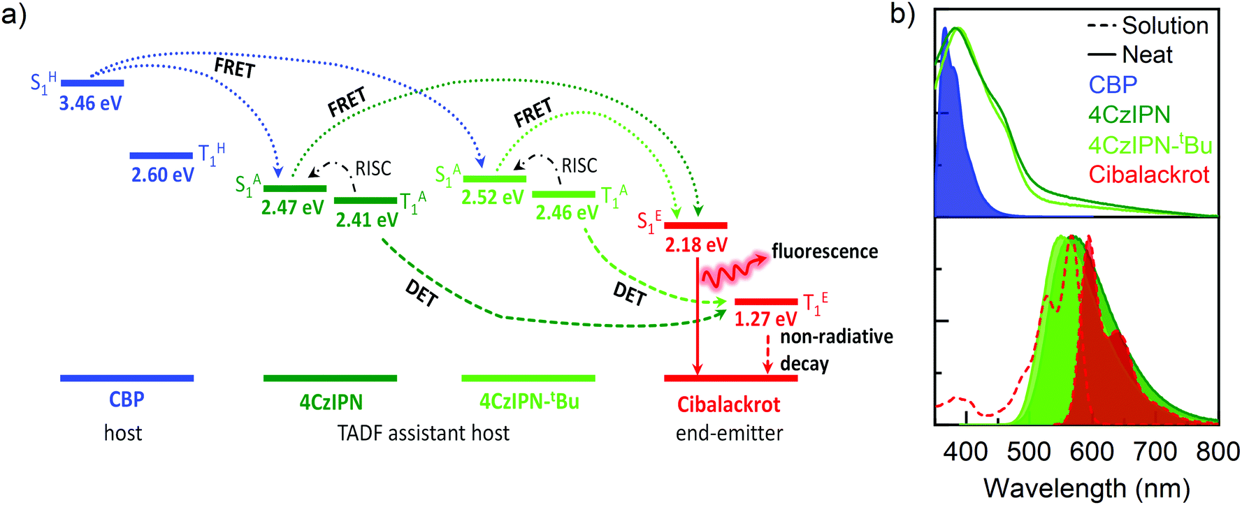 | ||
| Fig. 2 (a) Schematic illustration of energy levels and energy transfer processes in the ternary blend. The energy levels of CBP, 4CzIPN, and 4CzIPN-tBu were determined from neat films, and cibalackrot from toluene solution. Dotted arrows represent FRET, dashed arrows represent DET, dot-dash arrows represent RISC, and solid arrows represent radiative emission. (b) Absorption and photoluminescence (PL) (filled) of the CBP host in neat films (solid), and TADF assistant hosts, showing a good overlap of CBP PL with 4CzIPN/4CzIPN-tBu, and 4CzIPN/4CzIPN-tBu PL and cibalackrot absorption (dashed). | ||
The R0 values were found to be 3.4 nm for CBP → cibalackrot, 4.7 nm for 4CzIPN → cibalackrot, and 4.9 nm for 4CzIPN-tBu → cibalackrot. Due to the larger exchange radius, energy transfer is expected to occur in a cascading manner from CBP → 4CzIPN/4CzIPN-tBu → cibalackrot. Interestingly, the estimated R0 for 4CzIPN-tBu → cibalackrot is slightly higher than that for 4CzIPN → cibalackrot, resulting from a better overlap between the PL of 4CzIPN-tBu and the absorption of cibalackrot (integral overlaps of 1.45 × 10¹⁵ for 4CzIPN-tBu, and 1.11 × 10¹⁵ for 4CzIPN). Due to the non-radiative nature of triplet excitons in the fluorescent compounds, it is challenging to estimate the DET exchange radius, although previous studies have found it to be within a domain of 1–2 nm.21
As previously discussed, we aimed to study the kFRET and DET loss efficiencies (kDET) on device performances using two systems. In the first system, we used ternary blends of cibalackrot in TADF:CBP (≈30:70 mol%) with varying mol% of cibalackrot. In order to optimise the device performance,31 and realise efficient energy transfer between the CBP host and TADF-assistant dopant, high concentrations of TADF (i.e. 50:50 wt%, equivalent to a 30:70 molar ratio to CBP) have been employed in this work. By implementing a ternary blend with low doping concetrations, we specifically aimed to increase the intermolecular spacing (r) between the TADF and cibalackrot molecules to assist the supression of short-range DET, and simultaneously inhibit concentration quenching. The increased r is expected to give a reduction of kDET but with little impact on kFRET as the long-range FRET processes can still efficiently occur in the cascading manner as described previously. In the second system, we use a binary blend (host-free), composed of a neat TADF material and cibalackrot of varying mol%. By removing the CBP host, we attempt to increase kFRET through promoting interactions between the adjacent TADF and Cibalackrot molecules as kFRET ∝ 1/r (eqn (2)). However, while kFRET should increase with decreasing r, the removal of CBP will also lead to a simultaneous increase in kDET as a result of the increased concentration of the TADF material and its long triplet lifetime. Therefore, additional consideration of triplet diffusion and the resulting DET loss efficiencies was explored by comparing the 4CzIPN TADF material with its more sterically encumbered derivative, 4CzIPN-tBu (Fig. 1).
Photophysical properties
:70 mol% blend ratio of either 4CzIPN-tBu:CBP or 4CzIPN:CBP. Fig. S2a (ESI†) shows the normalised absorption and PL of 0.5–1.5 mol% cibalackrot doped in 4CzIPN-tBu:CBP, and 1.5 mol% cibalackrot/4CzIPN:CBP blend films (spin-coated from 0.5 wt% chloroform solution). As predicted, the absorption of the tertiary blends was dominated by both CBP and the TADF assistant dopant (4CzIPN or 4CzIPN-tBu) with a minimal contribution from cibalackrot. In contrast, PL was dominated by emission from cibalackrot, with little contribution from the other components. This implies that FRET is indeed occurring efficiently from CBP → 4CzIPN/4CzIPN-tBu → cibalackrot. The excited-state lifetimes of these blends were estimated from TCSPC prompt and delayed fluorescence decays as shown in Fig. S3a and c (ESI†). The PLQYs along with prompt (τp) and delayed (τd) lifetimes of the various blends are further summarised in Table S3 (ESI†). Increasing mol% of cibalackrot resulted in a decreased emission contribution from the TADF-dopant as FRET between the two materials increased. This is noted in the PL by a significant reduction of the emission peak at ≈540 nm, and the decreasing values of τp and τd, as there is progressively less delayed fluorescence from 4CzIPN-tBu. Additionally, the relative τp and τd of the ternary blends were found to be much faster than non-doped TADF:host blends, especially τd, which was reduced by a factor of 10, another indication that FRET is efficiently taking place from 4CzIPN-tBu → cibalackrot. The PLQYs of these blends showed a slight reduction with increasing cibalackrot mol% but were generally comparable varying between 74% and 79%. The PL spectra, τp, and τd were comparable between 1.5 mol% 4CzIPN-tBu:CBP and 4CzIPN:CBP blend films (Fig. S2a and S3a, c, ESI†). The PLQY of 1.5 mol% cibalackrot blend films was slightly higher for 4CzIPN-tBu:CBP (74%) compared with 4CzIPN:CBP (69%). This is in agreement with the prediction resulting from the comparison of R0 where FRET should be more efficient between 4CzIPN-tBu → cibalackrot resulting in higher PLQYs.
Device characteristics
To investigate the EL properties of these blends, OLEDs were fabricated using a solution-processed emissive layer (EML) with the following device architecture: ITO (100 nm)/PEDOT:PSS (30 nm)/EML (≈35 nm)/TPBi (65 nm)/Liq (2 nm)/Al (100 nm), where ITO, PEDOT:PSS, TPBi and Liq are indium tin oxide, poly(3,4-ethylenedioxythiophene):poly(styrenesulfonate), 2,2′,2′′-(1,3,5-benzinetriyl)-tris(1-phenyl-1H-benzimidazole) and lithium 8-quinolate, respectively. EML is the emissive layer, containing cibalackrot in TADF:host blends as summarised in Table 1. Fig. 3a shows the corresponding energy level diagram for the device architecture.| Blend ratio (mol%) | V on (V) | Max brightness (cd m−2) | EQE (%) | |||||
|---|---|---|---|---|---|---|---|---|
| Cibalackrot | TADF | Host | Max | 100 cd m−2 | 1000 cd m−2 | |||
| V on is the turn on voltage at 1 cd cm−2. | ||||||||
| 0.5 | 29.5 | 4CzIPN-tBu | CBP | 5.0 | 4595 | 15.3 | 14.9 | 8.4 |
| 1.0 | 29.0 | 4CzIPN-tBu | CBP | 4.8 | 5782 | 11.2 | 11.0 | 7.2 |
| 1.5 | 28.5 | 4CzIPN-tBu | CBP | 4.4 | 5277 | 8.7 | 8.0 | 4.5 |
| 1.5 | 28.5 | 4CzIPN | CBP | 4.4 | 4680 | 5.6 | 5.6 | 4.4 |
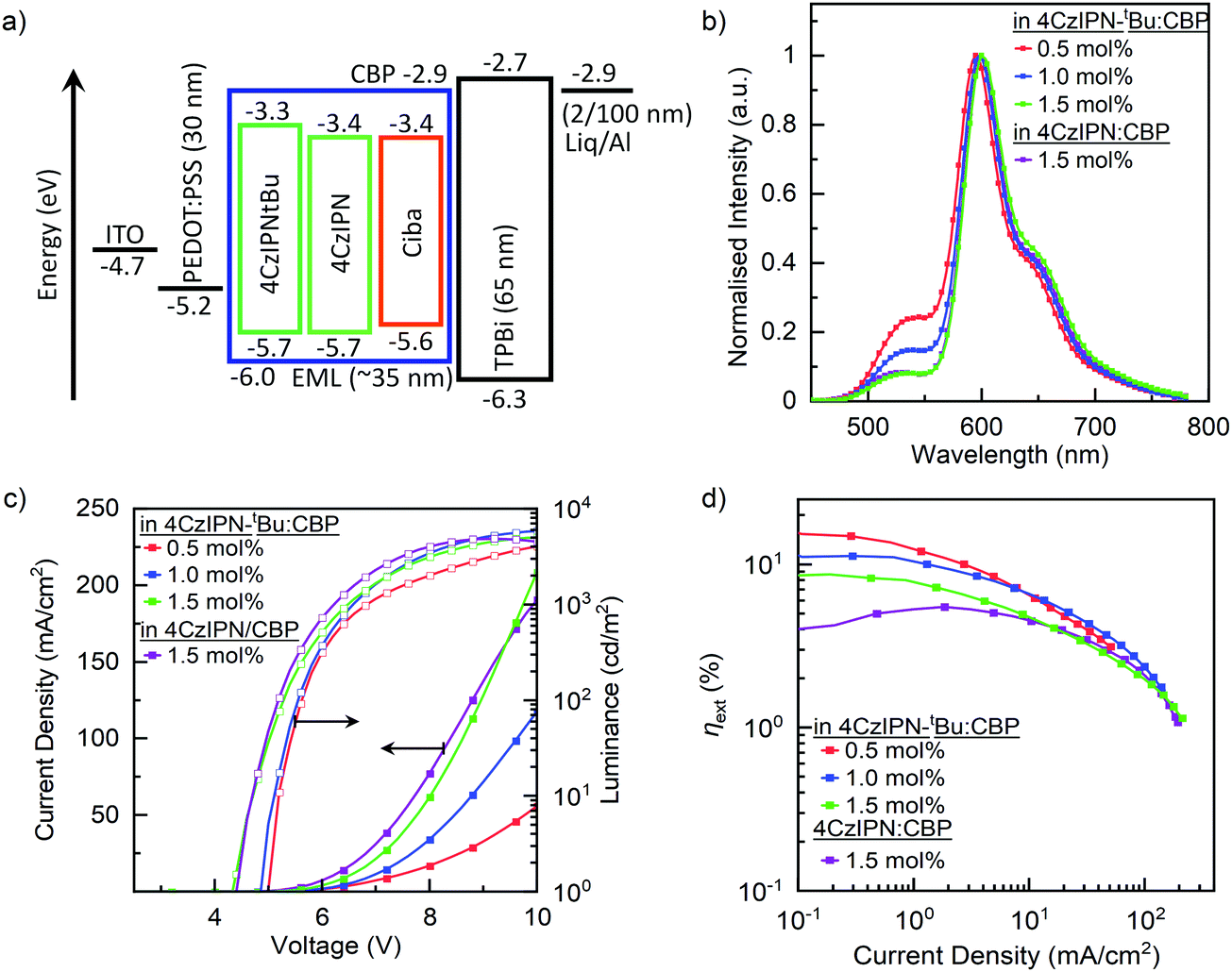 | ||
| Fig. 3 Device characteristics for OLEDs containing cibalackrot of varying mol% when blended in TADF:CBP (≈30:70 mol%). (a) Energy level diagram of the hyperfluorescent device architecture used in this study, (b) EL at EQEmax, (c) current density–voltage–luminance (JVL) characteristics, and (d) EQE versus the current density. | ||
:CBP (≈29.5:70 mol%) as the EML, producing a maximum EQE of 15.3% and an EQE of 14.9% at 100 cd m−2. The achieved device performances are comparable with thermally evaporated devices (Fig. S4, ESI†) and are higher than previously reported solution processed devices.21,22 When the concentration of cibalackrot was increased from 0.5 to 1.5 mol% in 4CzIPN-tBu:CBP devices, EQEmax decreases from 15.3% to 8.7%, although other device characteristics such as current densities, brightness, and light turn on voltage (Von) are improved. By comparison of the EL spectra in Fig. 3c, less emission from 4CzIPN-tBu was observed while increasing the cibalackrot dopant concentrations, similar to those observed in the PL spectra (Fig. S2a, ESI†). This is because by increasing the doping concentrations, the effective intermolecular spacing (r) is reduced, leading to more efficient kFRET from 4CzIPN-tBu → cibalackrot and hence more emission from cibalackrot instead of 4CzIPN-tBu.
However, as the relative EL contribution from 4CzIPN-tBu is not insignificant, we approximated the relative emission contributions from 4CzIPN-tBu at EQEmax by comparing the total integrated area of the EL curve to an overlapping area of emission from 4CzIPN-tBu; this gave the relative EL contributions from 4CzIPN-tBu to be 28, 18, and 10% for the respective 0.5, 1.0, and 1.5 mol% based devices (Fig. 3c). By applying this, we further estimated the EQE contribution from cibalackrot to be ≈11.0%, 9.1% and 7.8% for the 0.5, 1.0, and 1.5 mol% blend devices, respectively, agreeing with the decreasing trend observed previously. As the PLQYs of these two blends were similar, the achieved EQEs are far below what may theoretically be achieved (a max EQE of about 15% based on the film PLQY of 75%). Hence, the considerable reduction in EQEs is likely due to increased losses from DET as short-range interactions between 4CzIPN-tBu → cibalackrot increase with the higher doping concentrations of cibalackrot. Competing kDET may also contribute to a reduction of the kFRET efficiency under electrical injections. Conversely, the reduction in Von and the increasing current densities may be due to better ambipolar character within the blend films. Consequently, direct carrier recombination and charge trapping on cibalackrot can also occur more rapidly, leading to non-emissive triplet states which reduce the overall electroluminescence from the device upon decaying to the ground state.
Comparison of 4CzIPN-tBu:CBP and 4CzIPN:CBP is observed in OLED devices containing 1.5 mol% cibalackrot. As the TADF materials are dispersed in CBP, short-range interactions such as DET and aggregate quenching effects are expected to be suppressed, and both blends should show similar device performances. This was indeed observed, and both devices show a relatively similar current density of >100 mA cm−2, and a light turn on voltage, Von, of 4.4 V. The EL spectra at EQEmax were also found to be comparable (Fig. 3c). However, while there is significant quenching of electroluminescence in both devices, the losses from DET are more substantial in the 4CzIPN:CBP blend. Similar to the thin film photophysical properties, the observed EQEs at 100 cd m−2 are much lower in 4CzIPN:CBP at 5.6%, in comparison with 4CzIPN-tBu:CBP at 8.0%. As there is a significant difference between the electroluminescent performances, it is clear that the attachment of tert-butyl surface groups plays an essential role in reducing the overall emission loss from the device.
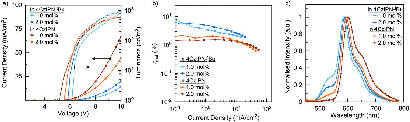 | ||
| Fig. 4 (a) Comparison of current density–voltage–luminance (J–V–L) characteristics, (b) comparison of EQEs versus current densities, and (c) comparison of EL at EQEmax for OLED with binary blend EML. | ||
| Blend ratio (mol%) | V on (V) | Max brightness (cd m−2) | EQE (%) | ||||
|---|---|---|---|---|---|---|---|
| Cibalackrot | TADF | Max | 100 cd m−2 | 1000 cd m−2 | |||
| 1.0 | 99.0 | 4CzIPN-tBu | 6.2 | 1462 | 7.7 | 4.0 | 2.1 |
| 2.0 | 98.0 | 4CzIPN-tBu | 6.0 | 1343 | 5.7 | 5.0 | 1.9 |
| 1.0 | 99.0 | 4CzIPN | 5.6 | 615 | 2.5 | 2.2 | — |
| 2.0 | 98.0 | 4CzIPN | 5.2 | 606 | 1.5 | 1.5 | — |
As noted earlier, the charge carrier properties in the binary blends seem better for the 4CzIPN devices. Interestingly, the 4CzIPN device efficiencies reflect more fluorescent-type emission with a brightness of <600 cd m−2 and an EQE of <2.5%, so perhaps all the excitons are funnelled straight to cibalackrot, without efficient RISC taking place. The triplet transport within the emissive layer would also be increased with a better frontier molecular orbital (FMO) overlap, and close packing between 4CzIPN → cibalackrot, making triplet excitons more likely to be lost through non-radiative DET, which may explain the stronger roll-off effect and reduced electroluminescence performances.
Conclusion
In summary, we have demonstrated solution-processed red hyperfluorescent devices with an unparalleled EQE of 15.3% using a cibalackrot:4CzIPN-tBu:CBP blended EML. By studying the use of either 4CzIPN or 4CzIPN-tBu as a TADF assistant dopant in both ternary and host-free binary blends, we found that the addition of tert-butyl surface groups gave a significant influence towards the device performance. These steric groups effectively suppressed triplet diffusion between the adjacent molecules by reducing the concurrent overlap of the HOMOs and LUMOs to reduce losses through DET. Overall, the device performances are comparable to thermally evaporated devices, and significantly higher than previously reported solution processed red hyperfluorescent OLEDs. These results show that cibalackrot is a promising new family for electroluminescence semiconductors.Experimental
General information
The organic compounds 4CzIPN-tBu and cibalackrot were synthesised according to previously reported procedures.22,32Photophysical measurements
Organic thin-films for optical measurements were fabricated on clean quartz by spin-coating. The substrates were cleaned with acetone and isopropanol and then treated with UV/ozone to remove the adsorbed organic species before deposition. Electronic absorption spectra were recorded using a PerkinElmer Lambda 950-PKA UV-vis spectrophotometer. Fluorescence spectra were recorded using a JASCO FP-8600 fluorometer. Absolute fluorescence quantum yields were measured using a Quantaurus-QY C11347-01 calibrated integrating-sphere system. Transient photoluminescence decay was recorded using a Hamamatsu Photonics Quantaurus-Tau C11367-03 system.Device fabrication and measurements
Glass substrates with a pre-patterned, 100 nm thick, 100 Ω sq−1 ITO coating were used as anodes. The substrates were washed by sequential ultrasonication in acetone, Semico clean, pure water, and isopropanol and then exposed to UV/ozone for 15 min to remove the adsorbed organic species. The PEDOT:PSS (Heraeus CleviosTM P VP.Al 4083) layer was spin-coated at a rotation speed of 500 rpm for 3 s and then 3000 rpm for 60 s on the top of ITO, and annealed at 200 °C for 10 min. The various EMLs were deposited by spin-coating from a chloroform solution (0.25 wt%) at a rotation speed of 1000 rpm for 60 s in a glove box, giving films with thicknesses of ca. 35 nm. The substrates were transferred into the evaporation chamber. Organic layers and the Al electrode were formed by thermal evaporation at a pressure lower than 1 × 10⁻⁴ Pa. The deposition rates of the organic layers were <1.0 Å s−1, while Liq and Al were deposited by the rates of 0.08 and 1.0–2.0 Å s−1, respectively. The J–V–L characteristics of the OLEDs were evaluated using a source meter (Keysight B2911A, Keysight 534 Technologies) and a luminance meter (CS-2000, Konica 535 Minolta, Japan) at a constant DC current at room temperature. The reproducibility of the device performance of the presented devices was confirmed by measuring at least four samples.Conflicts of interest
The authors declare no competing financial interest.Acknowledgements
The authors thank the Australian Research Council (ARC DP200103036), the Department of Industry, Innovation and Science (AISRF53765), and the JSPS Core-to-Core Program (JPJSCCA20180005) for financial support. N. R. W. was funded by an Australian Government Research Training Program Scholarship. This work was performed in part at the Queensland node of the Australian National Fabrication Facility Queensland Node (ANFF-Q), a company established under the National Collaborative Research Infrastructure Strategy to provide nano- and microfabrication facilities for Australia's researchers. M. M. acknowledges financial support from the JSPS KAKENHI Grant Number 19H02790, 20K21227 and 21H05401, and the Inamori Foundation.References
- M. A. Baldo, D. F. O’Brien, M. E. Thompson and S. R. Forrest, Phys. Rev. B: Condens. Matter Mater. Phys., 1999, 60, 14422–14428 CrossRef CAS.
- Q. Zhang, B. Li, S. Huang, H. Nomura, H. Tanaka and C. Adachi, Nat. Photonics, 2014, 8, 326–332 CrossRef CAS.
- K. Masui, H. Nakanotani and C. Adachi, Org. Electron., 2013, 14, 2721–2726 CrossRef CAS.
- H. Nakanotani, T. Higuchi, T. Furukawa, K. Masui, K. Morimoto, M. Numata, H. Tanaka, Y. Sagara, T. Yasuda and C. Adachi, Nat. Commun., 2014, 5, 4016 CrossRef CAS.
- T. Furukawa, H. Nakanotani, M. Inoue and C. Adachi, Sci. Rep., 2015, 5, 8429 CrossRef CAS.
- D. Zhang, L. Duan, C. Li, Y. Li, H. Li, D. Zhang and Y. Qiu, Adv. Mater., 2014, 26, 5050–5055 CrossRef CAS.
- L.-S. Cui, A. J. Gillett, S.-F. Zhang, H. Ye, Y. Liu, X.-K. Chen, Z.-S. Lin, E. W. Evans, W. K. Myers, T. K. Ronson, H. Nakanotani, S. Reineke, J.-L. Bredas, C. Adachi and R. H. Friend, Nat. Photonics, 2020, 14, 636–642 CrossRef CAS.
- Y. Wada, H. Nakagawa, S. Matsumoto, Y. Wakisaka and H. Kaji, Nat. Photonics, 2020, 14, 643–649 CrossRef CAS.
- S. O. Jeon, K. H. Lee, J. S. Kim, S.-G. Ihn, Y. S. Chung, J. W. Kim, H. Lee, S. Kim, H. Choi and J. Y. Lee, Nat. Photonics, 2021, 15, 208–215 CrossRef CAS.
- C.-Y. Chan, M. Tanaka, Y.-T. Lee, Y.-W. Wong, H. Nakanotani, T. Hatakeyama and C. Adachi, Nat. Photonics, 2021, 15, 203–207 CrossRef CAS.
- Y. T. Lee, C. Y. Chan, M. Tanaka, M. Mamada, U. Balijapalli, Y. Tsuchiya, H. Nakanotani, T. Hatakeyama and C. Adachi, Adv. Electron. Mater., 2021, 7, 2001090 CrossRef CAS.
- S. H. Han, J. H. Jeong, J. W. Yoo and J. Y. Lee, J. Mater. Chem. C, 2019, 7, 3082–3089 RSC.
- M. Tanaka, R. Nagata, H. Nakanotani and C. Adachi, ACS Appl. Mater. Interfaces, 2020, 12, 50668–50674 CrossRef CAS.
- S. Gottardi, M. Barbry, R. Coehoorn and H. van Eersel, Appl. Phys. Lett., 2019, 114, 73301 CrossRef.
- H. S. Kim, S. H. Lee, J. Y. Lee, S. Yoo and M. C. Suh, J. Phys. Chem. C, 2019, 123, 18283–18293 CrossRef CAS.
- M. Jakoby, B. S. Richards, U. Lemmer and I. A. Howard, Phys. Rev. B, 2019, 100, 045303 CrossRef CAS.
- T.-L. Wu, M.-J. Huang, C.-C. Lin, P.-Y. Huang, T.-Y. Chou, R.-W. Chen-Cheng, H.-W. Lin, R.-S. Liu and C.-H. Cheng, Nat. Photonics, 2018, 12, 235–240 CrossRef CAS.
- K. Albrecht, K. Matsuoka, K. Fujita and K. Yamamoto, Mater. Chem. Front., 2018, 2, 1097–1103 RSC.
- S. Prakash, M. Sims, I. Wyrsta, I. D. Parker, D. Kondakov and W. Gao, SID Dig. Tech. Pap., 2013, 44, 678–681 CrossRef.
- D. Chen, X. Cai, X.-L. Li, Z. He, C. Cai, D. Chen and S.-J. Su, J. Mater. Chem. C, 2017, 5, 5223–5231 RSC.
- A. Shukla, S. K. M. McGregor, R. Wawrzinek, S. Saggar, E. G. Moore, S.-C. Lo and E. B. Namdas, Adv. Funct. Mater., 2021, 31, 2009817 CrossRef CAS.
- A. Shukla, N. R. Wallwork, X. Li, J. Sobus, V. T. N. Mai, S. K. M. McGregor, K. Chen, R. J. Lepage, E. H. Krenske, E. G. Moore, E. B. Namdas and S.-C. Lo, Adv. Opt. Mater., 2020, 8, 1901350 CrossRef CAS.
- F. Verstraeten, S. Gielen, P. Verstappen, J. Kesters, E. Georgitzikis, J. Raymakers, D. Cheyns, P. Malinowski, M. Daenen, L. Lutsen, K. Vandewal and W. Maes, J. Mater. Chem. C, 2018, 6, 11645–11650 RSC.
- H. Dinçalp, G. M. Saltan, C. Zafer and D. A. Kıymaz, J. Mol. Struct., 2018, 1173, 512–520 CrossRef.
- M. Roders, M. A. Kolaczkowski, W. R. Hollingsworth, R. Seban, Y. Liu and A. L. Ayzner, J. Phys. Chem. C, 2019, 123, 27305–27316 CrossRef CAS.
- K. J. Fallon, A. Santala, N. Wijeyasinghe, E. F. Manley, N. Goodeal, A. Leventis, D. M. E. Freeman, M. Al-Hashimi, L. X. Chen, T. J. Marks, T. D. Anthopoulos and H. Bronstein, Adv. Funct. Mater., 2017, 27, 1704069 CrossRef.
- B. He, W. T. Neo, T. L. Chen, L. M. Klivansky, H. Wang, T. Tan, S. J. Teat, J. Xu and Y. Liu, ACS Sustainable Chem. Eng., 2016, 4, 2797–2805 CrossRef CAS.
- Y. J. Cho, K. S. Yook and J. Y. Lee, Adv. Mater., 2014, 26, 6642–6646 CrossRef CAS.
- B. Yurash, H. Nakanotani, Y. Olivier, D. Beljonne, C. Adachi and T. Q. Nguyen, Adv. Mater., 2019, 31, 1804490 CrossRef.
- J. L. Ryerson, A. Zaykov, L. E. Aguilar Suarez, R. W. A. Havenith, B. R. Stepp, P. I. Dron, J. Kaleta, A. Akdag, S. J. Teat, T. F. Magnera, J. R. Miller, Z. Havlas, R. Broer, S. Faraji, J. Michl and J. C. Johnson, J. Chem. Phys., 2019, 151, 184903 CrossRef.
- T. Yamanaka, H. Nakanotani, S. Hara, T. Hirohata and C. Adachi, Appl. Phys. Express, 2017, 10, 74101 CrossRef.
- R. Ishimatsu, T. Edura, C. Adachi, K. Nakano and T. Imato, Chem. – Eur. J., 2016, 22, 4889–4898 CrossRef CAS.
Footnote |
| † Electronic supplementary information (ESI) available. See DOI: 10.1039/d1tc04937b |
| This journal is © The Royal Society of Chemistry 2022 |