Low nonradiative energy losses within 0.2 eV in efficient non-fullerene all-small-molecule organic solar cells†
Ziyun
Huang‡
abcd,
Yanan
Shi‡
ab,
Yilin
Chang
ab,
Chen
Yang
ab,
Min
Lv
ab,
Yifan
Shen
abc,
Yanan
Liu
ae,
Jianqi
Zhang
 a,
Kun
Lu
 *ab and
Zhixiang
Wei
 ab
ab
aCAS key laboratory of nanosystem and hierarchical fabrication, CAS Center for Excellence in Nanoscience, National Center for Nanoscience and Technology, 100190 Beijing, China. E-mail: lvk@nanoctr.cn
bUniversity of Chinese Academy of Sciences, 100049 Beijing, China
cSino-Danish Center for Education and Research, Sino-Danish College, University of Chinese Academy of Sciences, 100190 Beijing, China
dInterdisciplinary Nanoscience Center (iNANO), Aarhus University, Denmark
eTianjin Key Laboratory of Molecular Optoelectronic Sciences, Department of Chemistry, School of Science, Tianjin University, Tianjin 300072, China
First published on 16th November 2021
Abstract
Despite the remarkable progress achieved in the field of non-fullerene acceptor (NFA)-based organic photovoltaics (OPVs) in recent years, the large energy loss remains a major factor limiting the power conversion efficiency (PCE) of OPVs. Although many studies on polymer OPVs have been reported, low energy loss systems with high efficiency are rarely reported with all-small-molecule organic-solar-cells (ASM-OSCs). This is partially because a low energetic offset between donors and acceptors is usually required to have a small energy loss, which could result in an insufficient exciton dissociation driving force, making the trade-off between the device performance and energy loss an important research focus. In this article, we report ASM-OSCs based on three small molecule donors ZR1-C2, ZR1-C3 and ZR1-C4 with small molecule NFAs BTP-C11-N2Cl, BTP-C9-N2F and BTP-C9-N4F. Charge carrier mobilities, exciton dissociation efficiency and charge collection efficiency were measured and calculated for blends ZR1-C3:TP-C11-N4Cl, ZR1-C3:BTP-C9-N2F and ZR1-C3:BTP-C9-N4F, revealing good charge transport properties. Morphology characterization methods such as AFM, TEM and GIWAXS have been employed, demonstrating excellent molecular compatibility and suitable phase separation with fibrous structures that provides efficient charge transport channels. By morphology and charge carrier optimization, the highest PCE of 14.29% was achieved with a small nonradiative energy loss of 0.2 eV which, to the best of our knowledge, is the highest PCE value for ASM-OSCs with a non-radiative voltage loss ≤ 0.2 eV, reaching a balance between high performance and low energy loss.
Introduction
Organic solar cells (OSCs) have been widely investigated and remarkable progress has been achieved in recent years, as they offer several advantages such as flexibility, light weight and low-cost fabrication.1–7 In the past 5 years, non-fullerene acceptor (NFA)-based organic photovoltaic devices (OPVs) have received extensive attention and pushed the power conversion efficiency (PCE) of single-junction OSCs to over 18% with polymer donors.8–13 Compared with polymers, small molecules have intrinsic advantages such as a definite chemical structure, easy purification process, and little batch-to-batch variation.14–16 A PCE of over 15% has been reported for all-small-molecule organic solar cells (ASM-OSCs), making them more promising toward commercialization, and have received massive attention recently.14,17–22 Although breakthroughs have been made, further improvement on the PCE of OSCs still remains a challenge, and large energy loss is considered a major factor limiting the PCE of OPVs. Many studies related to energy loss in polymer OPVs have been discussed,23–28 but low energy loss systems with high efficiency are rarely reported in ASM-OSCs. This is partially because low energetic offset between donors and acceptors is usually required to obtain small energy loss, which could result in an insufficient exciton dissociation driving force that leads to small current.27 Although efficient charge separation under low driving forces has been reported in several polymer systems,29,30 we believe that ASM-OSCs also have prospective potency for energy loss optimization. Previous research studies have shown that the open-circuit voltage (VOC) is usually proportional to the difference between the highest occupied molecular orbital (HOMO) of the donor and the lowest unoccupied molecular orbital (LUMO) of the acceptor. Taking acceptor Y6 as an example, the famous polymer donor PM6, with the HOMO energy level of −5.53 eV, exhibits a VOC of 0.835 when blended with Y6,31 while small molecule donor ZR1, with a higher HOMO of −5.32 eV, was reported to give a higher VOC of 0.861 eV,32 which conflicts with the previous empirical conclusion. Since energy loss is approximately the difference between the band-gap and VOC of the blend, small molecule donors may possess the potential to reach lower energy loss under a similar energetic offset when compared with polymers.In previous studies, adjusting the alkyl-chain branching position has been proposed as an efficient strategy to improve the photovoltaic performances of solar cells by controlling the crystallinity and molecular miscibility.33 In 2019, small molecule donor ZR1 was designed and reported, achieving a high efficiency of 14.34% with Y6.32 In 2020, Zhou et al. reported a series of donors ZR2-C1, ZR2-C2 and ZR2-C3, where the butyl and hexyl of ZR1 on the side-chain end groups were substituted with hexyl and octyl. By systematically moving the branching point away from the core moiety, the power conversion efficiencies of their blends were increased from 11.79% to 14.78%, with a simultaneous improvement in both FF and short circuit current (JSC). End group modulation is another popular method to tune the energy bandgaps and regulate the molecular aggregations in small molecule acceptors.34–37 Recently, an extended end group from the 2-(3-oxo-2,3-dihydro-1H-inden-1-ylidene)malononitrile (IC) to the 2-(3-oxo-2,3-dihydro-1H-cyclopenta[b] naphthalen-1-ylidene)malononitrile (NINCN) has been reported and an excellent result has been achieved in polymer OSCs.23 The enlarged conjugated area of the end group could enhance the molecular interaction and increase the HOMO–LUMO energy levels of acceptors,23,35,37 reducing the HOMO offset between the donor and acceptor materials, so that voltage loss is reduced and a high VOC is obtained.
In this study, based on the previously reported ZR1 and the strategy of alkyl-chain branching point modulation, we designed and synthesized small molecule donors ZR1-C2, ZR1-C3 and ZR1-C4, the molecular structures of which are shown in Fig. 1, and the photovoltaic parameters with acceptor Y6 are listed in Table S1 (ESI†). The highest efficiency of 15.12% has been achieved by ZR1-C3, with significant improvement in FF when compared with ZR1. Then, dithienothiophen[3,2-b]-pyrrolobenzothiadiazole (BTP)-based non-fullerene acceptor (NFA) with different halogen substitution were designed and synthesized, among which BTP-C9-N2Cl, BTP-C9-N2Cl and BTP-C11-N4Cl were shifted out for their poor solubility in chloroform. The remaining acceptors BTP-C11-N2Cl, BTP-C9-N2F and BTP-C9-N4F were then blended with ZR1-C3 to form ASM-OSCs. The molecular structures of the donor and acceptors are shown in Fig. 1a. The non-radiative voltage loss of all these three systems is ≤ 0.2 eV, which is rarely reported by ASM-OSCs and is almost near to those of inorganic solar cells based on Si.38 The optimized device based on ZR1-C3 as the donor and BTP-C9-N4F as the acceptor gave an excellent PCE of 14.29%, which, to the best of our knowledge, is the highest PCE value for ASM-OSCs with a non-radiative voltage loss ≤ 0.2 eV, achieving high PCE and high non-radiative voltage loss simultaneously.
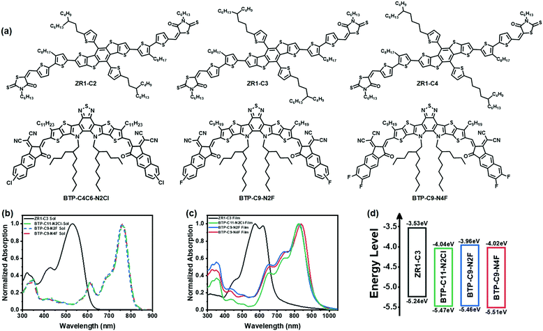 | ||
| Fig. 1 Molecular structures (a), normalized solution absorption spectrum (b), normalized film absorption spectrum (c) and energy levels (d) of ZR1-C3, BTP-C11-N2Cl, BTP-C9-N2F and BTP-C9-N4F. | ||
Results and discussion
In this study, the conventional structure of glass/ITO/PEDOT:PSS/active layer/PFN-Br/Ag was fabricated for all devices to investigate their photovoltaic performance. The molecular structures are shown in Fig. 1a and the optimized photovoltaic parameters are listed in Table 1. The 2-(3-oxo-2,3-dihydro-1H-cyclopenta[b] naphthalen-1-ylidene) malononitrile (NINCN) end group of acceptors enabled a high LUMO energy level, and thus a VOC as high as 0.90 V was obtained from ZR1-C3: BTP-C9-N2F and ZR1-C3: BTP-C11-N2Cl systems, which is higher than most of BTP-based non-fullerene small-molecule acceptors. By further increasing the substituted fluorine atoms on the end groups, a simultaneous increase in both JSC and FF appears with a small decrease in VOC, leading to an increase in efficiency from slightly above 11% to 14.29% in the ZR1-C3:BTP-C9-N4F system.| Active layers | V OC (V) | J SC (mA cm−2) | FF (%) | PCE (%) |
|---|---|---|---|---|
| ZR1-C3:BTP-C11-N2Cl | 0.89 (0.88 ± 0.01) | 20.06 (20.03 ± 0.85) | 61.23 (60.03 ± 1.20) | 11.01 (10.71 ± 0.30) |
| ZR1-C3:BTP-C9-N2F | 0.90 (0.89 ± 0.01) | 20.02 (19.96 ± 0.70) | 62.89 (61.48 ± 1.41) | 11.44 (11.01 ± 0.43) |
| ZR1-C3:BTP-C9-N4F | 0.86 (0.85 ± 0.01) | 23.63 (23.61 ± 0.37) | 69.75 (69.50 ± 0.88) | 14.29 (14.02 ± 0.27) |
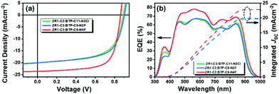
The current density–voltage (J–V) characteristics and external quantum efficiency (EQE) curves are plotted in Fig. 2. The calculated JSC from the EQE spectrum is 19.83 mA cm−2, 19.70 mA cm−2 and 22.86 mA cm−2 for ZR1-C3:BTP-C11-N2Cl, ZR1-C3:BTP-C9-N2F and ZR1-C3:BTP-C9-N4F, respectively, which is consistent with the values obtained from J–V curves (error within 5%). The shape of the EQE curves is almost identical, with ZR1-C3:BTP-C9-N4F exhibiting overall higher efficiency in the range of 450 to 1000 nm, indicating better light utilization and management. The charge carrier mobility of each device was determined by the space charge-limited current (SCLC) and is plotted in Fig. S1a and b (ESI†). The electron mobility was detected using the device architecture of glass/ITO/ZnO/active layer/PFN-Br/Al, while the hole mobility was determined using the glass/ITO/PEDOT:PSS/active layer/MoOX/Ag device structure. The electron/hole mobilities of devices with ZR1-C3:BTP-C11-N2Cl, ZR1-C3:BTP-C9-N2F and ZR1-C3:BTP-C9-N4F as active layers were calculated to be 4.21 × 10⁻⁴ cm2 V−1 s−1/1.48 × 10−4 cm2 V−1 s−1, 6.68 × 10⁻⁴ cm2 V−1 s−1/5.33 × 10−4 cm2 V−1 s−1, and 7.68 × 10⁻⁴ cm2 V−1 s−1/7.57 × 10−4 cm2 V−1 s−1, respectively. An overall higher carrier mobility and better balanced electron/hole mobility ratio (1.01) were achieved by ZR1-C3:BTP-C9-N4F when compared with others, providing better charge transport properties that led to a simultaneous increase in both JSC and FF.39,40
To further investigate the light absorption and exciton dissociation process, the dependences of photocurrent density (Jph) on the effective voltage (Veff) were measured and are plotted in Fig. S1c (ESI†). When the effective voltage is large enough (i.e., Veff ≥ 2 V), all photo-generated excitons are dissociated and Jph reaches saturation and is defined as Jsat. The Jsat is 21.80 mA cm−2 for the ZR1-C3:BTP-C11-N2Cl system, 20.80 mA cm−2 for the ZR1-C3:BTP-C9-N2F system and 23.99 mA cm−2 for the ZR1-C3:BTP-C9-N4F system, which is consistent with the measured JSC. Moreover, exciton dissociation efficiency (ηdiss) and charge collection efficiency (ηcoll) were obtained by calculating the ratio of Jph/Jsat. Under short-circuit conditions, ηdiss was calculated to be 92.04% for the ZR1-C3:BTP-C11-N2Cl system, 95.81% for the ZR1-C3:BTP-C9-N2F system and 98.29% for the ZR1-C3:BTP-C9-N4F system, while under maximum power conditions, ηcoll was calculated to be 78.36% for the ZR1-C3:BTP-C11-N2Cl system, 69.31% for the ZR1-C3:BTP-C9-N2F system and 83.21% for the ZR1-C3:BTP-C9-N4F system. The blend with BTP-C9-N4F as the acceptor exhibited the highest exciton dissociation rate as well as charge collecting efficiency among them, explaining its high FF and JSC.
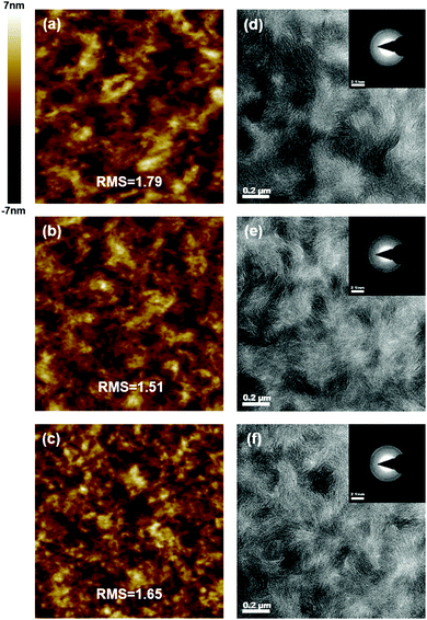
The surface morphology analysis of the active layers was conducted by atomic force microscopy (AFM), as shown in Fig. 3(a–c). The root mean-square (RMS) roughness is calculated to be 1.79, 1.51 and 1.65 for ZR1-C3:BTP-C11-N2Cl, ZR1-C3:BTP-C9-N2F and ZR1-C3:BTP-C9-N4F blends, respectively. Fairly low RMS values are obtained by all devices, indicating a smooth surface with nice molecular compatibility between the donor and acceptors. Relatively smaller domains were observed by the ZR1-C3:BTP-C9-N4F blend, which can avoid over-aggregation of the donor or acceptor.41,42 To gain more in-depth insight into the bulk morphology and phase distribution, transmission electronic microscopy (TEM) was conducted and is shown in Fig. 3(d–f). Clear fibrous structures are observed in all three blends, forming an efficient charge transport channel that supports high JSC and FF.43,44 One thing worth noticing is that a clear ring can be observed in the selected area electron diffraction (SAED) pattern shown in the inset of Fig. 3(d–f), which is rarely reported in ASM-OSCs and indicates good crystallinity. The diffraction signal is located at a distance of 0.357 nm for all three blends, corresponding to the (010) π–π stacking distance of ZR1-C3.45 This phenomenon further supports that the fibrous structure originates from the self-assembly of donor molecule ZR1-C3. Consistent with the AFM morphology, the ZR1-C3:BTP-C9-N4F blend formed an interconnected network structure with a smaller-sized domain, which can give more donor/acceptor interfaces that reduce the electron–hole recombination, leading to sufficient exciton separation.41,46 This is also consistent with previously calculated results.
To investigate the molecular packing and orientation of pristine films (Fig. S2, ESI†) as well as blend active layers (Fig. 4), two-dimensional grazing-incident wide-angle X-ray scattering (2D GIWAXS) was conducted. The d-spacing and crystal coherence length (CCL) values of (100) and (010) are listed in Table S2 (ESI†). The pristine donor ZR1-C3 film showed strong crystallinity with an edge-on orientation, whereas three acceptors showed a clear face-on orientation with similar weak crystallinity. In the blend films, the crystallinity of the donor was greatly affected by the addition of small molecule acceptors, as is shown in Fig. S3 (ESI†). After thermal annealing, an obvious increase in the crystallinity of both donors and acceptors can be observed, as evidenced by the appearance and narrowing of both (100) and (010) peaks. Ordered (11-1) diffraction peaks can be observed in the in-plane direction for blends with BTP-C9-N2F and BTP-C9-N4F as acceptors, which could be caused by the shortened alkyl substituents and the fluorine substituent in the end group.47–49 A stronger π–π interaction can be observed in the out-of-plane direction, indicating a preferential face-on orientation, which could be beneficial for the charge transport between the anode and cathode of solar cell devices.50,51 Moreover, the coexistence of face-on and edge-on orientations could facilitate the intermolecular charge transfer inside blends, giving high JSC and FF, promoting a high PCE with low energy loss.
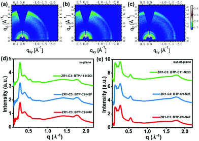 | ||
| Fig. 4 GIWAXS patterns of (a) ZR1-C3:BTP-C11-N2Cl, (b) ZR1-C3:BTP- C9-N2F and (c) ZR1-C3:BTP-C9-N4F. (d) In-plane and (e) out-of-plane line cuts of the corresponding GIWAXS pattern. | ||
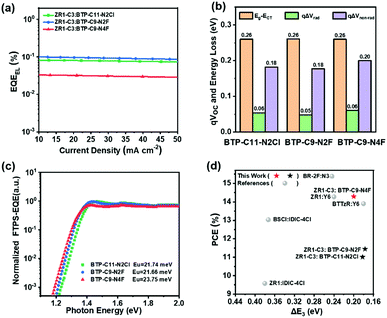
To further understand the reason for the various performances achieved by three similar acceptors, energy loss (Eloss) analysis was conducted. According to the Shockley–Queisser (SQ) limit model, the Eloss can be divided into the following:38
| Eloss = Eg–qVOC = (Eg−qVSQOC) + (qVSQOC–qVradOC) + (qVradOC–qVOC) = ΔE1 + ΔE2 + ΔE3 |
ΔE3 + qΔVnon–rad = qVradOC–qVOC = kT![[thin space (1/6-em)]](https://www.rsc.org/images/entities/i_char_2009.gif) ln ln![[thin space (1/6-em)]](https://www.rsc.org/images/entities/char_2009.gif) (EQEEL) (EQEEL) |
| Acceptors | E g [eV] | qV OC [eV] | qV SQOC [eV] | qV radOC [eV] | qV loss [eV] | ΔE1 [eV] | ΔE2 [eV] | ΔE3 [eV] |
|---|---|---|---|---|---|---|---|---|
| BTP-C11-N2Cl | 1.39 | 0.89 | 1.13 | 1.07 | 0.50 | 0.26 | 0.06 | 0.18 |
| BTP-C9-N2F | 1.39 | 0.90 | 1.13 | 1.08 | 0.49 | 0.26 | 0.05 | 0.18 |
| BTP-C9-N4F | 1.38 | 0.86 | 1.12 | 1.06 | 0.52 | 0.26 | 0.06 | 0.20 |
To gain more insight into the non-radiative voltage loss, the Urbach energy of pristine acceptors was measured by Fourier transform photocurrent spectroscopy external quantum efficiency (FTPS-EQE), as shown in Fig. 5c. A device structure of ITO/PEDOT:PSS/acceptor layer/PFN-Br/Ag was employed and the Urbach energy can be calculated by exponentially fitting of the tail of FTPS-EQE spectra following the equation56
Conclusions
In summary, we designed and synthesized a series of small molecule donors ZR1-C2, ZR1-C3 and ZR1-C4 by varying the alkyne chain branching point. Small molecule acceptors BTP-C11-N4Cl, BTP-C9-N2F and BTP-C9-N4F were blended with ZR1-C3, giving a high VOC with a small nonradiative energy loss ≤ 0.2 eV. Charge carrier mobilities, exciton dissociation efficiency and charge collection efficiency were measured and calculated, revealing good charge transport properties that support a high JSC. Morphology characterization methods such as AFM, TEM and GIWAXS showed a fairly smooth surface with low RMS and interconnecting fibrous structures, indicating the good miscibility between the donor and acceptor, and the efficient charge transport channel that supports high JSC and FF. A high PCE of 14.29% was achieved by the ZR1-C3:BTP-C9-N4F optimized device with low energy loss, which, to the best of our knowledge, is the highest PCE value among ASM-OSCs with a non-radiative voltage loss of ≤ 0.2 eV. The design of these kinds of small molecules is significant for the construction of high efficiency and low energy loss small molecule photovoltaics and shows the possibility of reaching a balance between the device performance and energy loss in ASM-OSCs.Conflicts of interest
There are no conflicts to declare.Acknowledgements
We acknowledge financial support provided by the National Natural Science Foundation of China (Grant No. 21822503 and 51973043) and the Youth Innovation Promotion Association, the Chinese Academy of Sciences.Notes and references
- L. Duan, H. Yi, Z. Wang, Y. Zhang, F. Haque, B. Sang, R. Deng and A. Uddin, Sustain, Energy Fuels, 2019, 3, 2456–2463 CAS.
- M. Kaltenbrunner, M. S. White, E. D. Glowacki, T. Sekitani, T. Someya, N. S. Sariciftci and S. Bauer, Nat. Commun., 2012, 3, 770 CrossRef.
- R. Søndergaard, M. Hösel, D. Angmo, T. T. Larsen-Olsen and F. C. Krebs, Mater. Today, 2012, 15, 36–49 CrossRef.
- Y. Li, Acc. Chem. Res., 2012, 45, 723–733 CrossRef CAS.
- L. Lu, T. Zheng, Q. Wu, A. M. Schneider, D. Zhao and L. Yu, Chem. Rev., 2015, 115, 12666–12731 CrossRef CAS.
- G. Li, R. Zhu and Y. Yang, Nat. Photonics, 2012, 6, 153–161 CrossRef CAS.
- K. Gao, S. B. Jo, X. Shi, L. Nian, M. Zhang, Y. Kan, F. Lin, B. Kan, B. Xu, Q. Rong, L. Shui, F. Liu, X. Peng, G. Zhou, Y. Cao and A. K. Jen, Adv. Mater., 2019, 31, 1807842 CrossRef.
- Q. Liu, Y. Jiang, K. Jin, J. Qin, J. Xu, W. Li, J. Xiong, J. Liu, Z. Xiao, K. Sun, S. Yang, X. Zhang and L. Ding, Sci. Bull., 2020, 65, 272–275 CrossRef CAS.
- L. Zhan, S. Li, X. Xia, Y. Li, X. Lu, L. Zuo, M. Shi and H. Chen, Adv. Mater., 2021, 33, 2007231 CrossRef CAS.
- Y. Lin, J. Wang, Z. G. Zhang, H. Bai, Y. Li, D. Zhu and X. Zhan, Adv. Mater., 2015, 27, 1170–1174 CrossRef CAS PubMed.
- J. Zhang, H. S. Tan, X. Guo, A. Facchetti and H. Yan, Nat. Photonics, 2018, 3, 720–731 CAS.
- Y. Cui, H. Yao, J. Zhang, K. Xian, T. Zhang, L. Hong, Y. Wang, Y. Xu, K. Ma, C. An, C. He, Z. Wei, F. Gao and J. Hou, Adv. Mater., 2020, 32, 1908205 CrossRef CAS PubMed.
- C. Yan, S. Barlow, Z. Wang, H. Yan, A. K. Y. Jen, S. R. Marder and X. Zhan, Nat. Rev. Mater., 2018, 3, 18003 CrossRef CAS.
- H. Chen, D. Hu, Q. Yang, J. Gao, J. Fu, K. Yang, H. He, S. Chen, Z. Kan, T. Duan, C. Yang, J. Ouyang, Z. Xiao, K. Sun and S. Lu, Joule, 2019, 3, 3034–3047 CrossRef CAS.
- S. D. Collins, N. A. Ran, M. C. Heiber and T.-Q. Nguyen, Adv. Energy Mater., 2017, 7, 1602242 CrossRef.
- J. Ge, Q. Wei, R. Peng, E. Zhou, T. Yan, W. Song, W. Zhang, X. Zhang, S. Jiang and Z. Ge, ACS Appl. Mater. Interfaces, 2019, 11, 44528–44535 CrossRef CAS.
- F. Pan, M. Luo, X. Liu, H. Jiang, Z. Wang, D. Yuan, Q. Wang, L. Qing, Z. Zhang, L. Zhang, Y. Zou and J. Chen, J. Mater. Chem. A, 2021, 9, 7129–7136 RSC.
- D. Hu, Q. Yang, H. Chen, F. Wobben, V. M. Le Corre, R. Singh, T. Liu, R. Ma, H. Tang, L. J. A. Koster, T. Duan, H. Yan, Z. Kan, Z. Xiao and S. Lu, Energy Environ. Sci., 2020, 13, 2134–2141 RSC.
- X. Wang, J. Wang, J. Han, D. Huang, P. Wang, L. Zhou, C. Yang, X. Bao and R. Yang, Nano Energy, 2021, 81, 2211–2855 Search PubMed.
- J. Ge, L. Xie, R. Peng, B. Fanady, J. Huang, W. Song, T. Yan, W. Zhang and Z. Ge, Angew. Chem., Int. Ed., 2020, 59, 2808–2815 CrossRef CAS.
- D. Hu, Q. Yang, Y. Zheng, H. Tang, S. Chung, R. Singh, J. Lv, J. Fu, Z. Kan, B. Qin, Q. Chen, Z. Liao, H. Chen, Z. Xiao, K. Sun and S. Lu, Adv. Sci., 2021, 8, 2004262 CrossRef CAS.
- L. Nian, Y. Kan, K. Gao, M. Zhang, N. Li, G. Zhou, S. B. Jo, X. Shi, F. Lin, Q. Rong, F. Liu, G. Zhou and A. K. Y. Jen, Joule, 2020, 4, 2223–2236 CrossRef CAS.
- Y. Shi, J. Pan, J. Yu, J. Zhang, F. Gao, K. Lu and Z. Wei, Sol. RRL, 2021, 5, 2100008 CrossRef CAS.
- Z. Zhang, Q. Wu, D. Deng, S. Wu, R. Sun, J. Min, J. Zhang and Z. Wei, J. Mater. Chem. C, 2020, 8, 15385–15392 RSC.
- Y. Zeng, D. Li, Z. Xiao, H. Wu, Z. Chen, T. Hao, S. Xiong, Z. Ma, H. Zhu, L. Ding and Q. Bao, Adv. Funct. Mater., 2021, 11, 2101338 CAS.
- T. J. Wen, Z. X. Liu, Z. Chen, J. Zhou, Z. Shen, Y. Xiao, X. Lu, Z. Xie, H. Zhu, C. Z. Li and H. Chen, Angew. Chem., Int. Ed., 2021, 60, 12964–12970 CrossRef CAS.
- D. Qian, Z. Zheng, H. Yao, W. Tress, T. R. Hopper, S. Chen, S. Li, J. Liu, S. Chen, J. Zhang, X. K. Liu, B. Gao, L. Ouyang, Y. Jin, G. Pozina, I. A. Buyanova, W. M. Chen, O. Inganas, V. Coropceanu, J. L. Bredas, H. Yan, J. Hou, F. Zhang, A. A. Bakulin and F. Gao, Nat. Mater., 2018, 17, 703–709 CrossRef CAS.
- Y. Qin, S. Zhang, Y. Xu, L. Ye, Y. Wu, J. Kong, B. Xu, H. Yao, H. Ade and J. Hou, Adv. Energy Mater., 2019, 9, 1901823 CrossRef.
- J. Liu, S. Chen, D. Qian, B. Gautam, G. Yang, J. Zhao, J. Bergqvist, F. Zhang, W. Ma, H. Ade, O. Inganäs, K. Gundogdu, F. Gao and H. Yan, Nat. Energy, 2016, 1, 16089 CrossRef CAS.
- D. Baran, T. Kirchartz, S. Wheeler, S. Dimitrov, M. Abdelsamie, J. Gorman, R. S. Ashraf, S. Holliday, A. Wadsworth, N. Gasparini, P. Kaienburg, H. Yan, A. Amassian, C. J. Brabec, J. R. Durrant and I. McCulloch, Energy Environ. Sci., 2016, 9, 3783–3793 RSC.
- R. Yu, G. Wu and Z. A. Tan, J. Energy Chem., 2021, 61, 29–46 CrossRef.
- R. Zhou, Z. Jiang, C. Yang, J. Yu, J. Feng, M. A. Adil, D. Deng, W. Zou, J. Zhang, K. Lu, W. Ma, F. Gao and Z. Wei, Nat. Commun., 2019, 10, 5393 CrossRef PubMed.
- R. Zhou, Z. Jiang, Y. Shi, Q. Wu, C. Yang, J. Zhang, K. Lu and Z. Wei, Adv. Funct. Mater., 2020, 30, 2005426 CrossRef CAS.
- W. Gao, X. Ma, Q. An, J. Gao, C. Zhong, F. Zhang and C. Yang, J. Mater. Chem. A, 2020, 8, 14583–14591 RSC.
- H. Feng, N. Qiu, X. Wang, Y. Wang, B. Kan, X. Wan, M. Zhang, A. Xia, C. Li, F. Liu, H. Zhang and Y. Chen, Chem. Mater., 2017, 29, 7908–7917 CrossRef CAS.
- R. Qin, D. Wang, G. Zhou, Z.-P. Yu, S. Li, Y. Li, Z.-X. Liu, H. Zhu, M. Shi, X. Lu, C.-Z. Li and H. Chen, J. Mater. Chem. A, 2019, 7, 27632–27639 RSC.
- T. Liu, X. Pan, X. Meng, Y. Liu, D. Wei, W. Ma, L. Huo, X. Sun, T. H. Lee, M. Huang, H. Choi, J. Y. Kim, W. C. Choy and Y. Sun, Adv. Mater., 2017, 29, 1604251 CrossRef.
- J. Yao, T. Kirchartz, M. S. Vezie, M. A. Faist, W. Gong, Z. He, H. Wu, J. Troughton, T. Watson, D. Bryant and J. Nelson, Phys. Rev. Appl., 2015, 4, 014020 CrossRef.
- J. Yuan, Y. Xu, G. Shi, X. Ling, L. Ying, F. Huang, T. H. Lee, H. Y. Woo, J. Y. Kim, Y. Cao and W. Ma, J. Mater. Chem. A, 2018, 6, 10421–10432 RSC.
- Q. Liang, J. Han, C. Song, X. Yu, D.-M. Smilgies, K. Zhao, J. Liu and Y. Han, J. Mater. Chem. A, 2018, 6, 15610–15620 RSC.
- B.-H. Jiang, C.-P. Chen, H.-T. Liang, R.-J. Jeng, W.-C. Chien and Y.-Y. Yu, Dyes Pigm., 2020, 181, 108613 CrossRef CAS.
- L. Ye, H. Hu, M. Ghasemi, T. Wang, B. A. Collins, J. H. Kim, K. Jiang, J. H. Carpenter, H. Li, Z. Li, T. McAfee, J. Zhao, X. Chen, J. L. Y. Lai, T. Ma, J. L. Bredas, H. Yan and H. Ade, Nat. Mater., 2018, 17, 253–260 CrossRef CAS.
- Z. Liu and N. Wang, Dyes Pigm., 2021, 187, 109111 CrossRef CAS.
- R. Zhou, C. Yang, W. Zou, M. Abdullah Adil, H. Li, M. Lv, Z. Huang, M. Lv, J. Zhang, K. Lu and Z. Wei, J. Energy Chem., 2021, 52, 228–233 CrossRef.
- X. Yang, J. Loos, S. C. Veenstra, W. J. Verhees, M. M. Wienk, J. M. Kroon, M. A. Michels and R. A. Janssen, Nano Lett., 2005, 5, 579–583 CrossRef CAS PubMed.
- Q. An, J. Wang, W. Gao, X. Ma, Z. Hu, J. Gao, C. Xu, M. Hao, X. Zhang, C. Yang and F. Zhang, Sci. Bull., 2020, 65, 538–545 CrossRef CAS.
- D. Han, T. Kumari, S. Jung, Y. An and C. Yang, Sol. RRL, 2018, 2, 1800009 CrossRef.
- Y. Cho, T. H. Lee, S. Jeong, S. Y. Park, B. Lee, J. Y. Kim and C. Yang, ACS Appl. Energy Mater., 2020, 3, 7689–7698 CrossRef CAS.
- Y. Zhang, Y. Cho, J. Lee, J. Oh, S.-H. Kang, S. M. Lee, B. Lee, L. Zhong, B. Huang, S. Lee, J.-W. Lee, B. J. Kim, Y. Li and C. Yang, J. Mater. Chem. A, 2020, 8, 13049–13058 RSC.
- Y. Lin, F. Zhao, Q. He, L. Huo, Y. Wu, T. C. Parker, W. Ma, Y. Sun, C. Wang, D. Zhu, A. J. Heeger, S. R. Marder and X. Zhan, J. Am. Chem. Soc., 2016, 138, 4955–4961 CrossRef CAS PubMed.
- Y. Lin, Q. He, F. Zhao, L. Huo, J. Mai, X. Lu, C. J. Su, T. Li, J. Wang, J. Zhu, Y. Sun, C. Wang and X. Zhan, J. Am. Chem. Soc., 2016, 138, 2973–2976 CrossRef CAS PubMed.
- Y. Wang, D. Qian, Y. Cui, H. Zhang, J. Hou, K. Vandewal, T. Kirchartz and F. Gao, Adv. Funct. Mater., 2018, 8, 1801352 Search PubMed.
- D. Veldman, S. C. J. Meskers and R. A. J. Janssen, Adv. Funct. Mater., 2009, 19, 1939–1948 CrossRef CAS.
- X. Liu, X. Du, J. Wang, C. Duan, X. Tang, T. Heumueller, G. Liu, Y. Li, Z. Wang, J. Wang, F. Liu, N. Li, C. J. Brabec, F. Huang and Y. Cao, Adv. Energy Mater., 2018, 8, 1801699 CrossRef.
- K. Vandewal, K. Tvingstedt, A. Gadisa, O. Inganäs and J. V. Manca, Phys. Rev. B: Condens. Matter Mater. Phys., 2010, 81, 125204 CrossRef.
- C. Kaiser, O. J. Sandberg, N. Zarrabi, W. Li, P. Meredith and A. Armin, Nat. Commun., 2021, 12, 3988 CrossRef CAS PubMed.
- Z. Zhang, Y. Li, G. Cai, Y. Zhang, X. Lu and Y. Lin, J. Am. Chem. Soc., 2020, 142, 18741–18745 CrossRef CAS PubMed.
Footnotes |
| † Electronic supplementary information (ESI) available. See DOI: 10.1039/d1tc04264e |
| ‡ These authors contributed equally to this work. |
| This journal is © The Royal Society of Chemistry 2022 |

