 Open Access Article
Creative Commons Attribution 3.0 Unported Licence
Electronic structure engineering for electrochemical water oxidation
Pravin
Babar
abc,
Javeed
Mahmood
 abc,
Raghu V
Maligal-Ganesh
abc,
Seok-Jin
Kim
abc,
Zhonghua
Xue
abc and
Cafer T.
Yavuz
abc,
Raghu V
Maligal-Ganesh
abc,
Seok-Jin
Kim
abc,
Zhonghua
Xue
abc and
Cafer T.
Yavuz
 *abc
*abc
aOxide & Organic Nanomaterials for Energy & Environment (ONE) Lab, Physical Sciences and Engineering (PSE), King Abdullah University of Science and Technology (KAUST), Thuwal 23955, Saudi Arabia. E-mail: cafer.yavuz@kaust.edu.sa
bKAUST Catalysis Center, Physical Sciences and Engineering (PSE), King Abdullah University of Science and Technology (KAUST), Thuwal 23955, Saudi Arabia
cAdvanced Membranes and Porous Materials Center (AMPMC), Physical Sciences and Engineering (PSE), King Abdullah University of Science and Technology (KAUST), Thuwal 23955, Saudi Arabia
First published on 12th September 2022
Abstract
The oxygen evolution reaction (OER) is the primary challenge in renewable energy storage technologies, specifically electrochemical water splitting for hydrogen generation. The development of affordable, robust, and efficient OER electrocatalysts plays a prominent role in water splitting by lowering the reaction kinetics barrier and boosting the performance of the process. This review discusses the recent progress in probing the electronic structure of catalytically active materials and its relevance to OER activity. We have aimed to emphasize state-of-the-art engineering strategies for modulating the electronic structure to exhibit ideal OER performance, including doping, alloying, generation of oxygen vacancies, heterostructure realization, and strain engineering. Finally, we summarize the existing challenges and opportunities in electronic structure modulation for future electrocatalyst development.
1. Introduction
Since the 19th century, fossil fuels such as coal, natural gas, and oil have become the primary energy source to sustain human activities.1,2 The large-scale consumption of fossil fuels caused by unprecedented industrialization and rapid population growth, however, has resulted in detrimental environmental consequences and prompted the quest for more sustainable energy sources.3–5 In this regard, rigorous efforts have been undertaken to shift the energy burden to renewable energy, such as those sourced from solar, tidal, and wind. The supply of energy from these sources, however, is intermittent and region/season dependent, hindering their widespread implementation.6 To address this, renewable energy storage and conversion in the form of fuels and value-added chemicals is often proposed.7 Among the candidates, hydrogen (H2) is at the forefront, because it has a high gravimetric energy density and is environmentally benign.8,9 But hydrogen is currently produced from steam reforming or partial oxidation of methane, or coal gasification. All these processes are fossil fuel based, with the added drawback that the purity of H2 produced is also not high.10 Not surprisingly, H2 production through electrochemical water splitting has recently become an elegant and eco-friendly way to generate high purity H2 at room temperature.11–13Electrochemical water splitting is a thermodynamically uphill reaction, which consists of two half-cell reactions: the cathodic hydrogen evolution reaction (HER) and the anodic oxygen evolution reaction (OER) as described in eqn (1) and (2), respectively.14
| HER: 2e− + 2H+(aq) → H2(g) | (1) |
| OER: 2H2O(l) → 4H+(aq) + O2(g) + 4e− | (2) |
In ideal reaction conditions, a thermodynamic potential of 1.23 V is needed to drive electrochemical water splitting. A practical water electrolyzer requires a much higher potential due to the overpotentials on both of the electrodes (anode and cathode).15–17 HER is a comparatively simple two-electron transfer process involving adsorption of H+ ions and desorption of H2. OER, on the other hand, is more complicated, owing to sluggish oxygen evolution kinetics.18,19 The OER is a four electron and proton coupled reaction with electron transfer occurring at each step of the four steps involving various reaction intermediates (e.g., MOH, M–O, MOOH, and O2) with oxygen produced as the final product (M is a catalytically active metal center).20,21 Consequently, a large overpotential is required to overcome the OER kinetic energy barrier. Therefore, it is challenging to develop an efficient, cost-effective, and stable electrocatalyst for OER that can enhance the reaction rate and improve the overall efficiency of water splitting devices.
Over the past decade, numerous electrode materials have been developed and studied as electrocatalysts for OER. So far, the state-of-the-art IrO2 and RuO2 exhibit the best catalytic OER activity, but their low terrestrial availability and high cost limit their use in large scale applications.22–24 Therefore, significant research has been directed toward developing earth-abundant transition-metal-based electrocatalysts including oxides, layered double hydroxides (LDH), nitrides, sulfides, selenides, and perovskite-based materials.25–34 The transition-metal-based catalysts proved to have lower cost, higher natural abundance, unique electronic and mechanical properties, and good OER performances.16,27,35,36 Despite the advances made so far on fabricating OER electrocatalysts with well-defined structures as well as ex situ characterizations, there is still room for improvement in the electrochemical activity and stability of transition metal-based catalysts.
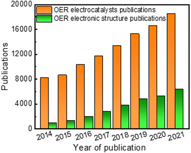
Apart from material type, several strategies have been explored to enhance electrocatalytic performance, including chemical composition tuning,19 morphology and phase control,37 defect engineering,38 and electronic structure modulation.16 Generally, the most basic structural characteristics, such as specific surface area and porous microstructure of the catalyst, have been studied as the key parameters for improving electrochemical performance for OER. For instance, the mass transfer rate and the number of active sites have been substantially enhanced in high surface area catalysts like 3D structures, 2D nanosheet structures, 1D nanorod/nanowire structures, and 0D nanoparticles.37,39 Despite extensive efforts in synthetic tuning, improvements in electrochemical performance of great significance are challenging to attain. This is because the overall electrocatalytic performance of a catalyst is often governed by its electronic structure, more than anything else. In the past few years, research dabbling in electronic structure modulation to overcome the sluggish kinetics of OER has steadily gathered steam (Fig. 1). For example, in 2014 there were more than 8100 papers on the topic of OER electrocatalysts, among them around 930 papers pay specific attention on strategies to modulate electronic structure. A few recent review and perspective articles summarized the development of noble and non-noble metal-based OER electrocatalysts with an emphasis on a given synthetic methodology or a specific electronic structure modulation strategy or classes of materials that can improve OER performance.40–42 However, there is a lack of an overall understanding and explanation of the relationship between electrochemical properties and electronic structure towards the development of electrocatalysts for water splitting applications. Therefore, we believe our review is a timely and critical overview of recent progress in the electronic structure modulation of electrocatalysts for enhanced OER performance.
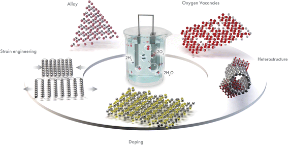
In this review, we summarize key advances in regulating the electronic structure of electrocatalytic materials for enhanced OER. We have identified the best electronic structure modulation methods as doping, alloying, oxygen vacancy generation, heterostructure, and strain engineering (Fig. 2). These approaches tune the electronic structure and improve the OER performance. We have included a detailed discussion on how the respective electronic structure tuning strategies can lead to enhanced OER activity. Such strategies provide new insights into the design and construction of an efficient electrocatalyst. Finally, we have discussed some existing challenges in these efforts and provided recommendations for future research directions.
2. Fundamentals of oxygen evolution reaction (OER)
One of the main reasons that limit water splitting systems from being practical is the sluggish kinetics of the OER. The OER is a four-electron transfer process which increases the complexity of the overall electrolysis, and requires higher energy to overcome the kinetic barrier.43 It is favorable in an alkaline electrolyte when compared to neutral or acidic media. In the acidic or neutral electrolyte, the free hydroxyl groups (OH) are absent, so the generation of OH* by breaking the H–OH bond from water molecules has a high energy barrier for the OER initiation. It results in slow OER kinetics while drawing high overpotential. The Gibbs free adsorption energies (ΔG) in the four-electron transfer step are shown in Fig. 3. The process involves (i) adsorption of H2O at the catalyst surface, (ii) formation of reaction intermediates from H2O (OH(ad), H+, e−), (iii) conversion of OH(ad) to O(ad), along with the generation of an additional proton and electron (iv) formation of the O–O bond via OOH(ad), an additional proton and an electron, and lastly (iv) desorption of oxygen from the catalyst surface, accompanied by the release of an additional proton and electron, with the overall process involving the total release of 4 protons and 4 electrons.44 For an ideal catalyst, the Gibbs free energy for every elementary step should be equal (ΔG1 = ΔG2 = ΔG3 = ΔG4), but in the case of the real catalysts, the chemisorption energy of the intermediates follow the order: ΔG3 > ΔG1 = ΔG2 > ΔG4.45,46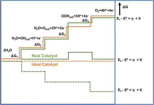 | ||
| Fig. 3 Gibbs free energy plot of OER versus reaction coordinate for the reactive intermediates (horizontal lines), the energetics of a real catalyst and an ideal catalyst has been represented by orange and green lines respectively.45 Copyright 2010, Wiley-VCH. | ||
As mentioned above, OER involves the formation of high-energy intermediates, requiring a substantial amount of energy to transcend the free energy barrier.47,48 Therefore, electronic structure modulation of catalytic materials is necessary to overcome these kinetic barriers, ensuring favorable reaction pathways with optimum free energy changes for the adsorption of the reaction intermediates at the catalyst surface. The ensuing strategies to achieve electronic structure modulation help in beneficial changes to adsorption energy that lower these kinetic barriers. These aid in reducing the overpotential of OER for these modified catalysts, attempting to bring it closer to that for an ideal catalyst (1.23 V).
3. Electronic structure modulation strategies for the OER electrocatalysts
3.1. Doping
Doping electrocatalysts have been reported as the most effective method to modulate electronic structure at the atomic level, which helps to improve water dissociation and optimize the adsorption capacity for the reaction intermediates. It generates lattice defects, which enhances the amount of available active sites in an electrocatalyst. Doping metal atoms (single metal or multimetallic) into transition metal-based catalysts such as layered double hydroxides (LDH), oxides, or chalcogenides serve as a promising strategy for enhancing the electrochemical activity.25,49,50 Due to the variation in the atomic radii and the electronic configuration of the dopant, the original lattice is likely to be altered and induced a local electronic redistribution. Moreover, doping may increase the adsorption energy of reaction intermediates because of the change in electronic structure. Many reports demonstrated that metal doping successfully improved catalytic performance.16,51–54 Among these, Fe incorporation is frequently established in that it enhances the electrochemical OER performance of Ni and Co-based catalysts.18,55 In the early 1980s, studies by Corrigan56 and Młynarek et al.57 found that Fe impurities enhance the OER performance. After these groundbreaking studies, Boettcher et al. further verified this argument by preparing NiOx, CoOx, NiyCo1−yOx, Ni0.9Fe0.1Ox, IrOx, MnOx, and FeOx films of 2–3 nm thickness using a solution casting method.58 They found that Ni0.9Fe0.1Ox was the best catalyst with lower overpotential and also a lower Tafel slope. The enhancement of OER activity was attributed to the in situ formation of a layered double hydroxide (LDH) structure, which has more active sites than metal oxide or hydroxide. The same group also reported the effect of Fe incorporation in Ni(OH)2/NiOOH during the OER.49 A 30-fold increase in catalyst conductivity accompanied by the formation of the LDH phase was observed when Fe was incorporated into Ni(OH)2. Electrochemical results show an anodic shift of Ni redox peaks in NixFe1−xOOH catalysts with increasing x.Advanced spectroscopic techniques provide further insight into what addition of a dopant into these various catalysts achieves. Friebel and co-workers50 used X-ray absorption spectroscopy (XAS) using high energy resolution fluorescence detection (HERFD) to reveal the role of Fe3+ in a Ni1−xFexOH based electrocatalyst. A key finding was that Fe3+ in NiFeOH occupies octahedral sites with short Fe–O bond distance induced by edge-sharing with surrounding [NiO6] octahedra. Further computational calculations identified that Fe cations were the active sites instead of Ni in mixed Fe–Ni oxyhydroxide. Similar findings have been reported for Fe doped Co-based electrocatalysts,18,19,59 which suggest that Fe incorporation has a promoter influence on Co and Ni-based catalysts. Using Mössbauer spectroscopy60 Jamie and co-workers revealed61 that Fe in an NiFe LDH existed as Fe4+ and was not the active site of the catalyst and instead functioned as an effective dopant to drastically enhance the OER performance of the Ni atoms. Görlin et al. used differential electrochemical mass spectrometry (DEMS) and X-ray absorption spectroscopy (XAS)62 to indicate that Ni in pure NiOOH electrode changes redox state from Ni2+ to Ni3+ or Ni4+ during the OER process, while in a mixed Ni–Fe electrocatalyst, Ni remains in the Ni2+ state, which might be responsible for the enhancement of the catalytic performance (Fig. 4a and b). Zhang and co-workers showed enhancement in the OER performance of NiO by Li doping, which could be due to electronic structure modifications.63 The results revealed that generation of hole states at 1.1 eV above the Fermi level and enlarged hybridization degree of O 2p–Ni 3d by Li-doping optimize the adsorption energies of OH intermediates (Fig. 4c).63
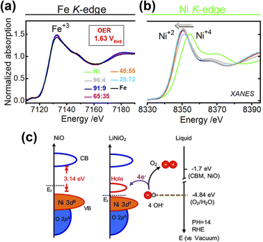 | ||
| Fig. 4 X-ray absorption spectra and electronic structure analysis of electrocatalysts (a) X-ray absorption spectrum of Fe K-edges and (b) Ni K-edges.62 Copyright 2017, American Chemical Society (c) schematic diagram for electronic structures of NiO and LiNiO2 (left) and energy diagram at the oxide–liquid interface on the vacuum level scale at pH = 14 (right); the redox level for O2/H2O (red dashed line) is −4.84 eV, the CB minimum (CBM) level for NiO is −1.7 eV according to the formula: ECBM = Ebandgap − Eionization, (Ebandgap = 3.7 eV, Eionization = 5.4 eV).63 Copyright 2017, American Chemical Society. | ||
A key aspect of doping metal atoms into pristine materials is the effect this has on the density of states at the Fermi level, with potential benefits for their catalytic behavior. Li and co-workers showed Co doping in Cu7S4 enhances the OER performance due to the optimized electronic structure of active sites.64 The calculated density of states (DOS) for Co-doped Cu7S4 is closer to the Fermi level than that of pristine Cu7S4, indicating that the concentration of charge carrier and the electronic conductivity can be effectively enhanced by the introduction of Co atoms. The Co-doped Cu7S4 improved OER performance even at a low overpotential of 270 mV to reach 10 mA cm−2. Wang et al. showed that nitrogen doping could regulate adsorption sites in the nanostructured ultrathin CoFe LDHs.65 Nitrogen doping redistributes the electron density of adjacent Co or Fe atoms, which optimize the adsorption energy of OER intermediates, thus enhancing electrocatalytic performance. Based on the theoretical analysis, Niu et al. showed that doping FeOOH with selenium (Se) lowers the energy barrier for the OER rate-limiting step and also enhances intrinsic activity.66
Doping or substituting transition metals in spinel metal oxides has also become an effective way to tune the electronic structure and enhance the OER performances of these versatile materials. Recently, doping spinel-based Co3O4 with Ni, Cu, Zn and Fe has been widely reported, and their effect on the electronic structure and electrochemical behavior have also been investigated.25,67–69 In the case of the Zn–Co spinel structure, Zn substitutes the Co2+ in tetrahedral sites and Co3+ remains in the octahedral sites. The enhancement in OER performance of ZnxCo3−xO4 compared to Co3O4 emerges from the altered electronic and structural nature of substituted tetrahedral sites. Choi and co-workers prepared spinel-type ZnCo2O4 and Co3O4 electrocatalysts to show these effects.70 The results suggest that ZnCo2O4 has better OER performance (η = 390 mV at 10 mA cm−2) than Co3O4 (η = 450 mV at 10 mA cm−2), which may be due to Co2+ in Co3O4 being catalytically inactive. Driess and co-workers reported the superior efficiency of ZnCo2O4 electrocatalyst to that of Co3O4 for the OER.71 The reason for the better catalytic activity was attributed to a higher amount of accessible octahedral Co3+ sites induced by preferential loss of zinc ions from the surface of the ZnCo2O4 electrocatalyst. Further, Xu and co-workers did a systematic study of spinel ZnFexCo2−xO4 oxides (x = 0–2.0) for the OER.72 The enhanced OER performance is attributed to enlarged Co 3d and O 2p covalency brought about by 10–30 atom% Fe substitution as it facilitates the injection/extraction of electrons from oxygen (Fig. 5a and b).
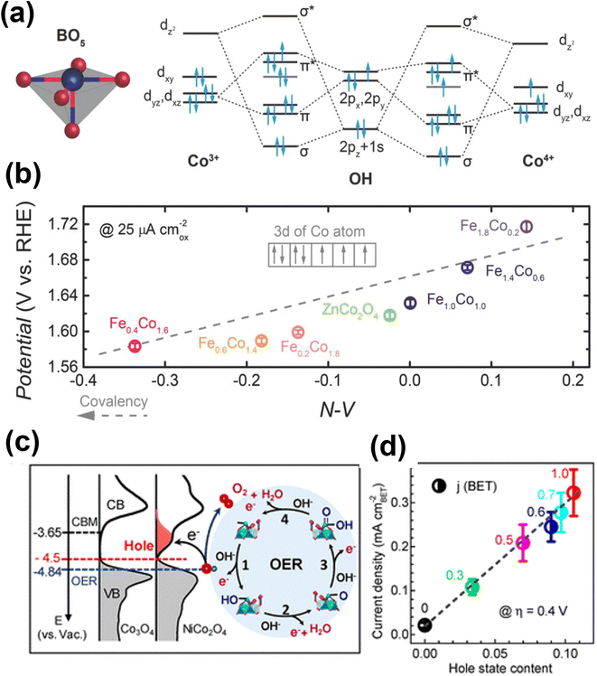 | ||
| Fig. 5 Performance and computational studies of oxide based OER electrocatalysts (a) molecular orbitals diagrams for the Co–OH (Co3+, Co4+) bonding at the surface of spinel oxides. (b) The OER activity, evaluated by the potentials at a current density of 25 μA cmox−2, as a function of the N–V parameter.72 Copyright 2018, Wiley-VCH. (c) Left panel: the measured occupied and unoccupied density of states (DOS) near the EF for Co3O4 and NiCo2O4; the energy level is relative to vacuum level (vs. Vac); the redox level for O2/H2O (blue line) is −4.84 eV; the hole state level is −4.5 eV for NiCo2O4 and the CBM level for Co3O4 is −3.65 eV. Right panel: schematics of the four-step reaction pathway of OER. (d) Correlation of specific OER activity (current density at η = 0.4 V) with the amount of hole state extracted from O K edge XAS spectra.76 Copyright 2019, American Chemical Society. | ||
Previous studies showed the significance of pre-oxidation of Co2+ to Co3+ or higher oxidation states in generating active sites of Co–OOH for OER.73 Papakonstantinou et al. synthesized CuCo2O4 nanoparticles (4.0 nm size) and anchored these on nitrogenated reduced graphene oxide (CuCo2O4/NrGO).74 The CuCo2O4/NrGO catalyst demonstrated enhanced OER performance due to the presence of Cu2+ ions at octahedral sites. Recently, Pentcheva and co-workers theoretically investigated the effect of Fe and Ni doping on Co3O4 (001) surface for the OER.75 The results suggest that the Ni doping at the octahedral site on the surface layer reduces the η from 0.46 to 0.34 V. Similarly, Fe doping at the tetrahedral Co termination lowers η from 0.63 to 0.37 V with octahedral Co remaining in the active site. Zhang and co-workers systematically studied the relationship between electronic structure and the OER activity of NixCo3−xO4 (x = 0–1).76 The XPS analysis reveals that incorporation of Ni3+ ions shifts the occupied valence band maximum by 0.27 eV towards the Fermi level (EF) and generates a new hole (unoccupied) state located at ∼1 eV above EF, which reduces the energy barrier for electron transfer to enhance the kinetics (Fig. 5c and d).
Incorporating more than one element to enhance the electrochemical performance of the electrocatalyst is garnering significant research scrutiny. Tang and co-workers developed Co and Ce doped Ni3S2 (Co/Ce-Ni3S2/NF) nanosheets on nickel foam by a one-step hydrothermal method.77 The co-doped Co and Ce are uniformly distributed inside the host sulfide, providing more active sites and increasing electrical conductivity. The incorporation of metallic elements into Ni3S2 has been considered as an effective strategy to alter the electronic structure to a disordered state, which increases the density of states (DOS). The DFT calculations further revealed that Ni3S2 displayed more metallic states near the Fermi level after Co and Ce doping, with the electronic conductivity being significantly increased and electron transport accelerated. Using a simple hydrothermal method, Wang et al. reported highly active Ru and Ni co-doped Co3O4 (Ru/Ni-Co3O4) nanoparticles.78 Doping Ru atoms into octahedral sites of spinel oxide Co3O4 improves the intrinsic activity, while Ni creates abundant oxygen vacancies. By demonstrating high intrinsic activity and the exposure of more active sites, the optimized Ru/Ni-Co3O4 shows a low overpotential for OER (290 mV at 10 mA cm−2). Similarly, Cheng and colleagues79 prepared Ru and Ni dual-doped CoP (Ru, Ni-CoP) porous nanofibers. Dual metal-doping (Ru and Ni) can modulate the electronic structure compared to single metal-doping. The Ru, Ni-CoP exhibit low free energy of 1.65 eV compared to Ru-CoP (1.80 eV) and Ni-CoP (1.83 eV) (Fig. 6a and b), revealing a higher adsorption capacity for *OOH. This enhanced adsorption capacity results from the higher valence state of Co caused by dual-metal doping. Recently, Kim and colleagues prepared Co, Nb dual-doped MoS2 nanosheets on TiO2 hollow spheres (Co, Nb-MoS2/TiO2 HSs), wherein the synergy between the hollow spherical structure of the TiO2 core and the MoS2 shell was exploited for enhanced electron transfer.80 Additionally, the Co and Nb doping further modified the electronic structure of the MoS2 to boost the OER performance. As shown in (Fig. 6c), DOS results indicate the electronic state of Co, Nb-MoS2/TiO2 HSs is closer to the Fermi level and higher than its counterparts, thus facilitating easier electron transfer and enhancing the adsorption of the intermediates. Qi and co-workers synthesized nanosheets of Co3O4 co-doped with both Mn and S that exhibited enhanced OER activity in comparison to the pristine Co3O4 nanosheets or Co3O4 doped only with either Mn or S.81 While Mn doping modifies the electronic structure around the Co center, enhancing the intrinsic activity of the active sites in Co3O4. On the other hand, S doping provides abundant S sites for proton desorption and increases the electrical conductivity. Furthermore, an increase in the proportion of Co3+ sites is also observed (Fig. 6d–f), which facilitates the four-electron transfer and the enhanced OER performance.
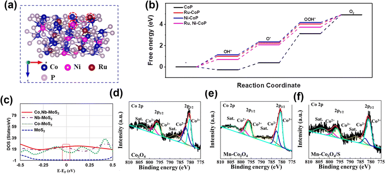 | ||
| Fig. 6 The role of double atom doping in OER electrocatalysts. (a) Atomic structure of Ru, Ni-CoP (111) surface, where Co, Ni, and Ru sites are marked with red circles. (b) Calculated OER Gibbs free energy diagram for CoP, Ru-CoP, Ni-CoP, and Ru, Ni-CoP.79 Copyright 2021, Elsevier. (c) Calculated DOS curves for MoS2, Co-MoS2, Nb-MoS2 and Co, Nb-MoS2.80 Copyright 2021, Elsevier. Co 2p spectra in (d) Co3O4, (e) Mn-Co3O4, and (f) Mn-Co3O4/S.81 Copyright 2019, Elsevier. | ||
3.2. Oxygen vacancy engineering
The introduction of oxygen vacancies in metal oxide nanomaterials is one of the most effective techniques to regulate their chemical and electronic characteristics. Oxygen vacancies improve the electrocatalytic performance via the enhancement of the synergy between the active sites and the neighboring atoms to enhance the DOS near the Fermi level.6 This further accelerates the electron transfer rate and instability of the metal–oxygen bond. Additionally, oxygen vacancies positively improve OER performance by significantly altering the energy level, conductivity, and adsorption properties of the materials. Various synthetic methods were used to generate oxygen vacancies, such as thermal treatment, reduction by NaBH4,82,83 ion exchange, plasma treatment,84,85 doping of ionic liquid,86 and in situ electrochemical activation.| 8Mn+ + NaBH4 + 2H2O → 8M(n−1)+ + NaBO2 + 8H+ |
Zheng and co-workers prepared 1D Co3O4 nanowires with rich oxygen vacancies using the NaBH4 reduction method.88 To prepare Co3O4 nanowires, they used a wet chemical growth method, and then as-prepared Co3O4 nanowires were soaked in 1 M NaBH4 solution for 1 h (Fig. 7a). After NaBH4 treatment, oxygen vacancies were created in Co3O4 nanowires and confirmed by XPS analysis. The DFT analysis revealed that due to oxygen vacancies, new defect states are generated and located in the band gaps (Fig. 7b). In addition, calculated formation energy suggests that the electrons at the oxygen vacancy defects can be easily excited into the conduction band, enhancing conductivity and the electrochemical activity of Co3O4 with a lower value of onset potential (1.52 V vs. RHE).
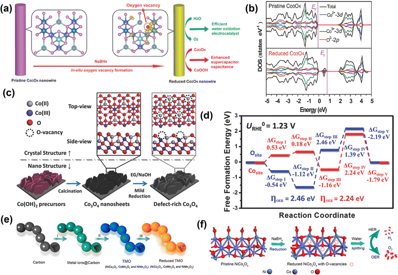 | ||
| Fig. 7 Reduction approach for vacancy generation in OER catalysts. (a) Schematic of the NaBH4 reduction for in situ creation of oxygen vacancies in Co3O4 NWs for efficient catalysis of oxygen evolution reaction and enhanced supercapacitor capacitance, (b) total densities of states (TDOS) and projected densities of states (PDOSs) of the pristine Co3O4 and the reduced Co3O4 (with oxygen vacancies).88 Copyright 2014, Wiley-VCH. A new state is formed within the bandgap of the reduced Co3O4. (c) Schematic illustration of creating oxygen vacancy defects on the surface of single-crystalline ultrathin Co3O4 nanosheets. The pristine Co3O4 nanosheets were grown directly on Ni foam substrate, then mildly reduced by ethylene glycol (EG) under alkaline condition, introducing, oxygen vacancy defects on the O-terminated {111} facets of single-crystalline Co3O4 nanosheets. (d) The calculated OER free energy diagram of the Co3O4 structure with/without oxygen vacancy.89 Copyright 2018, Wiley-VCH. (e) Schematic illustration of the formation process of R-TMO with a necklace-like multi-shelled hollow structure for water splitting. (f) Schematic illustration of creating oxygen vacancy defects on the surface of NCO after reduction, which is applied as a bifunctional electrocatalyst for water splitting to produce H2 and O2 in 1.0 M KOH aqueous solution.90 Copyright 2018, American Chemical Society. | ||
Sun and co-workers used a solvothermal reduction approach to create oxygen defects in single-crystalline Co3O4 nanosheets, as shown in Fig. 7c.89 The defect-rich Co3O4 shows a lower overpotential of 220 mV with a lower Tafel slope of 49.1 mV dec−1 for OER. Furthermore, the DFT calculation indicates a lower OER activation energy value of 2.24 eV on oxygen vacancy-rich Co3O4 than the pristine Co3O4 (2.46 eV) (Fig. 7d). Peng et al. prepared a unique necklace-like multi-shelled hollow structure of spinel transition metal oxides (NiCo2O4 (NCO), CoMn2O4, and NiMn2O4) using an adsorption–calcination–reduction strategy (Fig. 7e and f).90 The DFT calculations reveal a mechanism for enhancing catalytic performance based on a decrease in energy barrier for the formation of intermediates due to the introduction of oxygen vacancies. Zho and co-workers showed that an oxygen vacancy-rich NiFe-based catalyst yields a more than 2-fold increased current density at a low overpotential (370 mV @ 31 mA cm−2) in comparison to the pristine catalyst (370 mV @ 15 mA cm−2).91 Further, Zhu and co-workers used the reduction method to prepare ultrathin iron–cobalt oxide nanosheets (FexCoy-ONSs) with abundant oxygen vacancies as OER electrocatalysts.92 The FexCoy-ONSs showed excellent OER activity due to rich oxygen vacancies that could improve electronic conductivity and facilitate the adsorption of H2O onto nearby Co3+ sites.
Xie and colleagues successfully synthesized ultrathin nanosheets of the NiCo2O4 spinel with oxygen deficiencies by calcination of NiCo hydroxide in air at 300 °C.93 These ultrathin NiCo2O4 nanosheets with rich oxygen vacancies exhibited a high current density of 285 mA cm−2 at 0.8 V vs. Ag/AgCl. The theoretical calculations showed that oxygen vacancies confined in the ultrathin nanosheets could lower the adsorption energy of H2O, which enhances the OER efficiency. Cheng et al. have demonstrated that the electrocatalytic activity of MnO2 is boosted by generating oxygen deficiencies.94 The MnO2 with oxygen vacancies were prepared by simply heating in air or Ar atmosphere. Surprisingly the MnO2 samples heated in Ar (350 °C) and air (400 °C) outperformed the other samples that were annealed at the same temperatures but for longer durations. Hence generating an optimum concentration of oxygen vacancies was crucial wherein these oxygen vacancy enriched MnO2 samples showed a large current and lower overpotential. DFT study reveals that oxygen vacancies enhance the interaction between MnO2 surfaces and oxygen-containing species, and therefore reduce the kinetic barrier. Shi and co-workers successfully generated two different oxygen vacancy concentrations (δ = 0.25 and 0.50) in a perovskite oxide (PrBaCo2O6−δ) by annealing under pure N2 atmosphere for 30 min at 250 and 600 °C, respectively.95 They found that when oxygen vacancies were increased to δ = 0.50, the OER activity is reduced significantly. The reduced OER performance may be due to a significant reduction in eg filling of Co ions, which increases the electric resistivity and weakens the Co–O bond covalency. These results indicate that an optimal oxygen vacancy loading should be investigated for the high OER activity of any candidate materials.
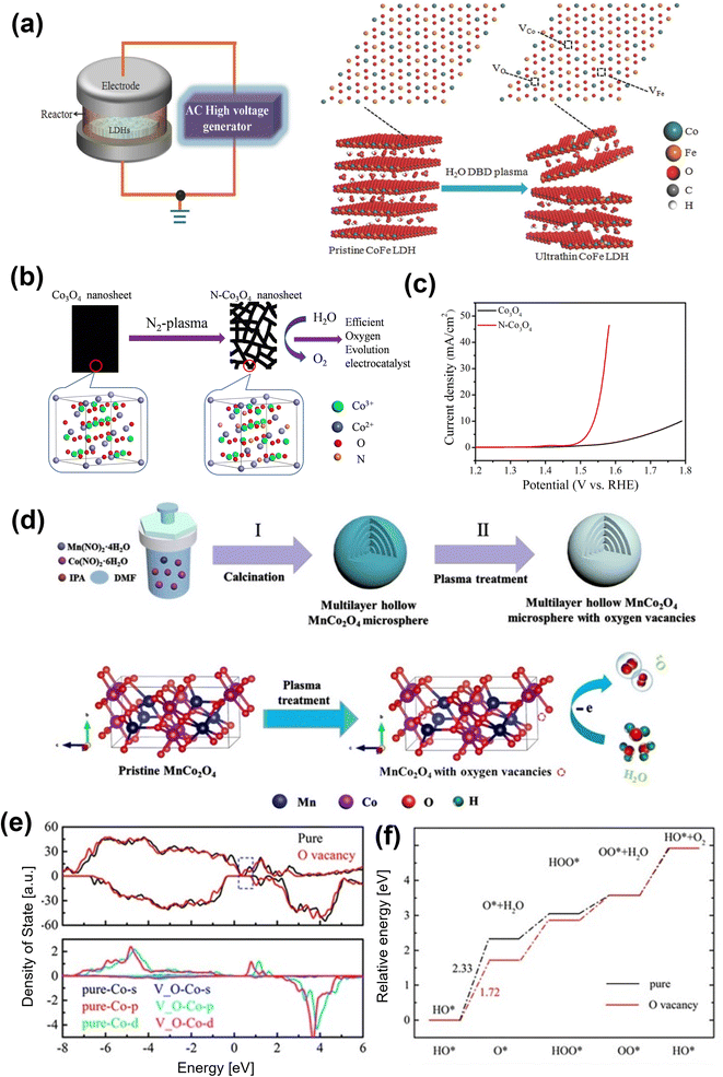 | ||
| Fig. 8 Plasma treatment for oxygen vacancy generating in OER electrocatalysts (a) schematic illustration of the water-plasma-enabled exfoliation of CoFe LDH nanosheets. The DBD plasma reactor is designed with the plate-to-plate electrode at 50 V powered by the AC high voltage generator.98 Copyright 2017, Wiley-VCH. (b) Schematic illustration of the preparation of the N-doped and etched Co3O4 nanosheets, (c) the polarization curves of the OER on pristine Co3O4 nanosheets and the N-doped Co3O4 nanosheets.101 Copyright 2017, IOP Publishing. (d) Illustration of the preparation of multilayer hollow MnCo2O4 microsphere (pristine MnCo2O4) and the introduction of oxygen vacancies (Vo-MnCo2O4). (e) The calculated density of states for MnCo2O4 (0 0 1) with and without oxygen vacancies (upper panel) and density of states projected on the surface Co atom (lower panel). (f) The energy profile for the OER process on MnCo2O4 with and without oxygen vacancies at zero potential.102 Copyright 2021, Elsevier. | ||
Zhi and co-workers adopted the Ar plasma strategy to introduce oxygen vacancies to Co3O4 and produced Co3O4−x.100 The oxygen vacancy-rich Co3O4−x promoted the reversible Co–O ↔ Co–O–OH redox reaction and lead to an enhancement in OER performance. Xu et al. prepared an efficient Co3O4 electrocatalyst for electrocatalytic OER with oxygen vacancies by a one-step Ar plasma-engraving strategy.85 The Co 2p XPS analysis reveals that in comparison to pristine Co3O4, the plasma-engraved Co3O4 surface has more Co2+ oxidation states, suggesting a partial reduction of Co3+ ions to Co2+ with the creation of oxygen vacancies on the Co3O4 surface. The Co3O4 nanosheets with oxygen vacancies significantly increased the surface area and the specific activity, resulting in better OER activity. The same group also reported N-doped nonporous Co3O4 nanosheets with oxygen vacancies by N2 plasma as an efficient OER electrocatalyst (Fig. 8b).101 An increase in active sites owing to the generated oxygen vacancies leads to higher electronic conductivity, resulting in excellent electrocatalytic activity with a lower overpotential of 310 mV at 10 mA cm−2 (Fig. 8c). Yang and co-workers recently used the plasma-engraving technique to create oxygen vacancies in multilayered MnCo2O4 microspheres (Fig. 8d).102 The defective MnCo2O4 increases the number of exposed active sites and promotes OER kinetics, further enhancing OER performance. Theoretical calculations confirm that the introduction of oxygen vacancies in MnCo2O4 can reduce the DOSs near the Fermi level and lower the Co d-band center, weakening the adsorption intermediates (Fig. 8e and f).
Gui and co-workers used doping and plasma treatment for creating abundant oxygen vacancies into a LaCoO3 perovskite.103 First, by substituting the lower valence Sr2+ ion for La3+ ion and then using Ar plasma treatment oxygen vacancies were generated. The prepared La1−xSrxCoO3−δ (x = 0.3) sample with doping and Ar plasma treatment showed excellent OER performance and stability, which is attributed to the presence of a large number of oxygen vacancies with high intrinsic activity of active sites. Similarly, the oxygen vacancy rich CoN104 (N2 plasma treatment), NiCo-LDH105 (Ar plasma treatment), NiFe-LDH/ATO106 (air plasma treatment), PrBa0.5Sr0.5Co1.5Fe0.5O5+δ (PBSCF)107 (Ar and H2 plasma treatment), NiO108 (Ar plasma treatment), and CoSe2 (Ar/O2 plasma treatment)109 electrocatalysts were successfully prepared.
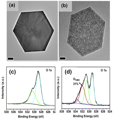 | ||
| Fig. 9 Ligand-assisted reduction method to generate oxygen vacancies on cobalt oxide nanoplates. TEM images of (a) α-Co(OH)2 and (b) CoOx. O 1s XPS spectra of (c) CoO-cal, and (d) CoOx.111 Copyright 2018, Elsevier. | ||
Ionic liquid-derived electrocatalysts can provide greater active site density and heteroatoms to alter their electronic structures, because of their structural tunability.112,113 They also have high thermal stability, tunable solvent properties, and good ionic conductivity. Inspired by this, Wang and co-workers generated oxygen vacancies into amorphous N, P and F tri-doped CoFe2O4 using an ionic liquid as a dopant.114 They revealed that the ionic liquid played an important role in the formation of the amorphous structure and oxygen vacancies in the catalyst, which are mainly responsible for enhancing the OER performance. Besides the generation of oxygen vacancies, ionic liquids, as mentioned earlier, can facilitate doping of metal atoms and heteroatoms. Kumbhar and co-workers have developed a simple method to prepare Co and heteroatom (S and N) co-doped carbon (Co10-NS-C) based OER electrocatalysts using ionic liquids.115 The doping of Co and N/S in carbon modulates the electronic structure of the material, facilitates the electron transfer in the superstructure, and enhances the OER performance with additional stability.
The flame treatment method was introduced as a simple, fast, and green way to generate more precise oxygen vacancies in a safe and open atmosphere.116,117 Zhou et al. used fast flame exposure in ambient conditions to create oxygen vacancies in NiFe-LDH nanosheet arrays.117 The inner core of a burner flame (4 to 5 cm away from flame gun muzzle) is oxygen-deficient, providing a reducing and yet high-temperature environment to generate oxygen vacancies in NiFe-LDH (Fig. 10a and b). After treatment for 30 s by reducing flame in the open environment, the engraved NiFe-LDH array shows improvement in OER performance.
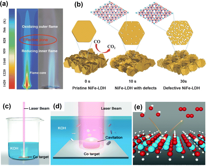 | ||
| Fig. 10 Schematic illustration of defective NiFe-LDH and L-CoOOH with oxygen vacancies prepared by fast reducing flame treatment and laser ablation in liquid for creating oxygen vacancies in transition-metal oxides. (a) Temperature distribution simulation of flame. (b) Morphology change of NiFe-LDH treated by flame for different periods of time.117 Copyright 2018, Wiley-VCH. (c) Schematic illustration of the synthesis of L-CoOOH via LAL and (d) the corresponding magnification of the laser irradiation region. (e) Schematic representation of L-CoOOH with abundant oxygen vacancies for the OER. Color code: white for H, red for O, cyan for Co, and transparent color for a vacancy.118 Copyright 2019, The Royal Society of Chemistry. | ||
Like the flame treatment method, laser ablation in liquid (LAL) is also a green, mild and effective approach to introduce oxygen vacancies into transition-metal oxide materials.118 Zhou and co-workers use LAL to prepare oxygen-rich CoOOH nanosheets by irradiating the Co target immersed in the KOH solution using a nanosecond laser for 20 min (Fig. 10c–e).118 The oxygen vacancy-rich CoOOH can optimize the adsorption of OER intermediates and improve electrical conductivity, thus enhancing OER performance. Furthermore, Co3O4 and SmMn2O5 with oxygen vacancies have been prepared using laser irradiation to exhibit excellent OER performance.119,120
3.3. Alloying
Alloying is considered an efficient strategy to optimize and improve the electrochemical performance of electrocatalysts because by adjusting the elemental composition the electronic structure of the catalysts can be modulated. It is profoundly different than doping methods because of the near stoichiometric presence of the secondary metals. The controlled synthesis of nanocrystal alloys has been demonstrated as an effective approach in various electrochemical reactions, such as OER, hydrogen evolution reaction, nitrogen reduction, and CO2 reduction, to enhance electrocatalytic activity.121–124 The basic principle of alloying the electrode's primary metal with others is to alter the electronic structure of the surface and near-surface atoms of catalyst to enhance the electrochemical activity. For example, the electrocatalytic activity is enhanced by alloying Ir with transition metals because the oxygen adsorption energy can be tuned, as explained by the d-band center theory.125,126 The d-band center theory describes the relationship between adsorption energy and d-band electrons. Guo and co-workers have prepared IrM (M = Co, Ni, CoNi) porous nanocrystals.127 The IrM nanocrystal electrocatalysts showed efficient electrocatalytic activity for OER. Their study revealed that Ir induces a ligand effect with transition metals, wherein the d-band center of Ir can be shifted far away from its original Fermi level through alloying. Thus, the adsorption energy of oxygen intermediates decreases, which is the key to improving the electrochemical OER performance (Fig. 11a and b). The same group prepared IrM (M = Ni, Co, Fe) bimetallic nanoclusters via a wet-chemical strategy without using surfactants.128 The in situ synthesis without the use of a capping agent (PVP), a cleaner surface, and the strong interaction between IrM nanoclusters enhanced the electrocatalytic performance. Guo and co-workers129 demonstrated that IrW nano-dendritic structure weakened the adsorption of oxygen intermediates. The projected density of states (Fig. 11c) showed that the overlap between the Ir 5d orbitals and O 2p orbitals of W-IrO2 (2.75 e− per Ir atom) is larger than that for IrO2 (2.59 e− per Ir atom), suggesting strong interaction between Ir and O in ternary oxide, which enhances the dissolution resistance of Ir and stabilizes the catalytic surfaces. Chen et al.130 synthesized ultrafine IrxNiy alloy using a wet-chemical method, followed by encapsulation in porous N-doped carbon (BMNC) (labeled as Ir3Ni2/BMC) derived from bimetallic zeolitic imidazolate frameworks (ZIFs). Owing to the alloying effect between Ni and Ir, increased surface area, and the generation of relatively more active sites, the Ir3Ni2/BMC exhibited excellent OER performance with a lower overpotential of 279 mV to deliver 10 mA cm−2. Zhang et al.131 reported Ir (4.9 wt%) incorporation into metallic Ni, significantly improving the electrochemical performance. The theoretical study indicated that the in situ generated amorphous Ir–Ni hydroxides around Ni–Ir core were the active species for the OER process, which enhanced the reaction kinetics for OER.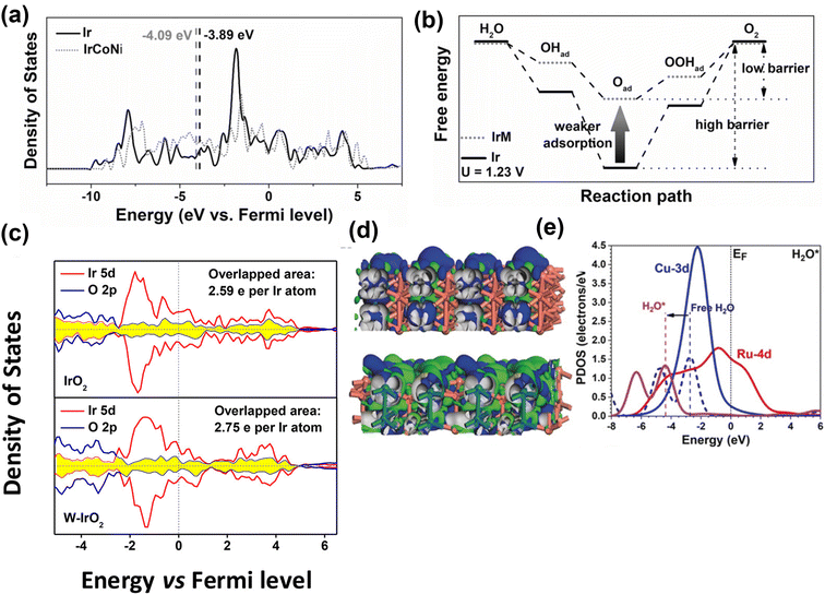 | ||
| Fig. 11 Computational studies of metal alloy electrocatalysts for OER. (a) Projected DOS of d bands of Ir (black) and IrCoNi models (red) with corresponding d-band center denoted by dash lines. (b) Schematic illustration of reaction paths for OER, indicating alloying Ir with M leads to weaker adsorption of oxygen-based intermediates, thus decreasing the barrier of reaction path.127 Copyright 2017, Wiley-VCH. (c) Projected density of states of IrO2 (up) and W-IrO2 (bottom) with the overlapped states of Ir 5d (red) and O 2p (blue) denoted by the shaded area (yellow).129 Copyright 2018, American Chemical Society. (d) The side views of the real-spatial contour plots for the bonding and anti-bonding orbitals near the EF of the pristine RuCu NPs (upper) and channel-rich RuCu NSs (lower). (e) The PDOS of H2O adsorption on RuCu NSs.132 Copyright 2019, Wiley-VCH. | ||
Huang and co-workers132 prepared channel-rich RuCu snowflake-like nanosheets composed of crystalline Ru and amorphous Cu. The excellent performance of RuCu nanosheets was attributed to highly active electron transfer and optimized electronic structures. The amorphous Cu and localization of bonding and anti-bonding orbitals near Fermi level (EF) change from Ru sites towards even distribution of the whole surface, supporting the electronic activation near the channel region (Fig. 11d). As shown in Fig. 11e, notable downshifting of H 1s and H2O 2p bands suggests stronger adsorption to guide the OER process. Feng and colleagues133 reported that graphitic carbon encapsulated NixRuy alloys (Ni0.6Ru0.4@C) exhibited excellent performance for OER in 1 M KOH. The experimental and DFT calculation results revealed that minor Ru alloying enabled morphological changes and electronic modulation of the electrocatalysts.
Although Ir and Ru-based electrocatalysts show better electrocatalytic activity in OER, non-precious metal alloy-based electrocatalysts are also noteworthy for use as OER catalysts. Hoang and Gerwirth134 prepared a NiFe film using an electrodeposition method. The prepared NiFe film showed enhanced OER performance with a lower overpotential of 300 mV at 100 mA cm−2 with excellent stability for 72 h. The improved performance of the NiFe film compared to pristine Ni indicates the alteration of electronic structure, which could be due to the interaction between Fe and Ni. Yin and co-workers135 prepared bimetallic IrNi alloy nanoparticles supported on nickel foam substrate using a hydrothermal method. The bimetallic IrNi nanoparticles exhibit excellent catalytic performance with a low overpotential of 200 mV at 20 mA cm−2 current density. Wang and colleagues prepared NiFe alloy nanoparticles encapsulated with N-doped carbon with hexagonal close-packed (hcp-NiFe@NC) and face-centered cubic (fcc-NiFe@NC) crystal structures.136 The hcp-NiFe@NC catalyst exhibits superior OER performance with 226 mV overpotential at 10 mA cm−2, which is much lower than fcc-NiFe@NC (292 mV @ 10 mA cm−2). The excellent performance of hcp-NiFe@NC was claimed to be due to the hcp structure (space group: P63/mmc) and favorable electronic properties to expedite the reaction on N-doped carbon. Liu et al. prepared a Fe–Co–P alloy sphere using Fe–Co metal–organic complex (MOC) as a precursor.137 The results suggested that the electrochemically induced high-valent Fe stabilized Co in a low valence state, which enabled the enhancement of OER performance and stability of the Fe–Co–P alloy. Wang and Co-workers fabricated nickel-iron diselenide hollow nano-chains (NFSHNCs) as an OER catalyst.138 They found that O* and OH* adsorption was found to be closely related to the iron and nickel sites. This strategy was used by several researchers to prepare metal alloys and study them extensively as OER electrocatalysts such as Ni–Mo alloy microspheres,139 Mo–Ni alloy nanoparticles,140 Ru–Ni nanosheets,141 and monolithic nanoporous Ni–Fe alloys.142
3.4. Heterostructure engineering
Heterostructures are conjoined electrocatalytic domains of independent nature and generally constructed by integrating different components such as metal–metal interfaces, metal–oxide interfaces, metal–non oxide (sulfide, nitride, selenide, and carbide) interfaces, and other interfaces (oxide–chalcogenide, oxide–oxide, phosphate-tungstate). Such interface engineering plays an essential role in improving the OER performance, which is due to: (a) modulating the electronic structure and therefore optimizing reaction intermediates, and (b) providing abundant catalytically active sites for electrolysis. It also helps to change the intrinsic catalytic activities of individual components, enabling catalysts with unique physicochemical properties towards electrochemical reactions. The electronic interactions among the different components create new active centers through the interface effect, enhancing the electrocatalytic performance. In short, interface engineering alters the electronic structure of an electrocatalyst, which could make it favorable for OER efficiency.Huang and co-workers constructed a Ni(OH)2–CeO2 heterostructure supported on carbon paper (NixCey@CP).143 The interface induced by the strong electronic interaction between hydroxide (Ni(OH)2) and oxide (CeO2) favorably modulated the binding strength between reaction intermediates and the electrocatalyst, which enhanced the OER performance (Fig. 12a and b). Zhai et al. fabricated a transition metal-based hierarchical bimetal oxide/sulfide heterostructure array (NiMoOx/NiMoS) by an oxidation/hydrogenation-induced surface reconfiguration strategy (Fig. 12c–e).144 The as-prepared NiMoOx/NiMoS heterostructure arrays exhibited excellent electrocatalytic performance for OER with 186, 225, 278, and 334 mV to reach 10, 100, 500, and 1000 mA cm−2, respectively. The excellent performance of transition bimetal oxides/sulfides heterostructure arrays was attributed to simultaneous modulation of component and geometric structures, and systematic optimization of charge transfer, increased active sites, and synergy between heterostructure interfaces. Jiang and co-workers145 designed metal alloys (Co3Mo) and metal oxide (CoMoOx) heterostructures (Co3Mo/CoMoOx) by a facile topological transformation through direct annealing of CoMoO4 under H2 atmosphere. The Co3Mo/CoMoOx heterostructure with abundant and strong coupling interfaces was shown to synergistically strengthen the conductivity of Co3Mo/CoMoOx and accelerate the charge transfer kinetics.
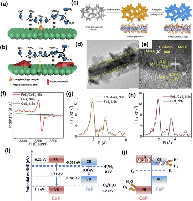 | ||
| Fig. 12 Heterostructure engineering strategies for OER. (a) Ni@CP and (b) Ni4Ce1@CP with the Ni(OH)2–CeO2 interfaces.143 Copyright 2018, American Chemical Society. (c) Illustration of transition bimetal oxides/sulfides heterostructure array synthesis. (d and e) HRTEM images of NiMoOx/NiMoS.144 Copyright 2020, Springer Nature. (f) EPR spectra of FeS2/CoS2 NSs, FeS2 NSs, and CoS2 NSs. (g) FeS2/CoS2 NSs and FeS2 NSs in R-space at the Fe K-edge and (h) FeS2/CoS2 NSs and CoS2 NSs in R-space at the Co K-edge. Copyright 2018, Wiley-VCH. (i) Schematic illustrations of the band structure of FeP and CoP before contact. (j) Charge transfer at the interface between CoP and FeP in the CoP-FeP heterostructures.146 Copyright 2019, American Chemical Society. | ||
Li et al.146 prepared defect-rich FeS2/CoS2 interface nanosheets. The synthesized FeS2/CoS2 showed remarkable OER activity with an overpotential of 302 mV at 100 mA cm−2, benefiting from the abundant defects present in the nanosheets interface structure. As shown in Fig. 12f, the electron paramagnetic resonance (EPR) spectra of FeS2/CoS2 with stronger EPR signal suggested abundant S vacancies compared to FeS2 and CoS2. Also, peak intensities of Fe–S and Fe–Fe pairs in the extended X-ray absorption fine structure (EXAFS) spectrum of FeS2/CoS2 were lower than FeS2, further indicating disordered and defective interfaces (Fig. 12g and h). Feng et al. demonstrated that a MoS2/Ni3S2 heterostructure exhibited excellent OER performance due to a precise interface that was synergistically favoring the chemisorption of oxygen-containing intermediates147 on the catalyst surface. Ai and co-workers148 showed non-precious metal phosphide heterostructures (CoP-FeP) as efficient electrocatalysts. A hierarchical branched CoP-FeP heterostructure is directly grown on a carbon cloth (CC). The n-type CoP semiconductor had a bandgap of 1.71 eV and conduction band position at −0.21 eV vs. normal hydrogen electrode (NHE), while FeP featured a bandgap of 0.8 eV with a conduction band position of −0.059 (Fig. 12i and j). The CoP displayed a lower work function than that of the FeP and due to intimate contact between CoP and FeP, the electrons flowed from CoP to FeP. This was mainly because of the built-in electric field at the interface until the work function equilibrium is reached. The optimized electron density and electronic potential distribution at the surfaces was thought to promote charge transfer to adsorbates and strengthen the chemical adsorption, thus enhancing electrocatalytic activity.
Another common strategy to improve electrochemical performance and stability is hybridizing electrocatalysts with carbonaceous materials. Yu et al.149 prepared Ni3FeN nanoparticles on reduced graphene oxide (Ni3FeN/r-GO) as efficient electrocatalysts. The excellent performance of Ni3FeN/r-GO heterostructures was attributed to abundant active sites and high electrical conductivity of bimetallic nitrides, and efficient mass transport of the r-GO framework. The DOS calculations (Fig. 13a) indicated that the band structure of Ni3FeN was consecutive near the Fermi level, suggesting Ni3FeN was intrinsically metallic, suggesting a strong covalent interaction between Ni, Fe, and N. The Ni3N and Fe3N have only one metal track to contribute DOS value, which indicates that at the Ni3FeN and r-GO interface, the number of electrons transferred from Ni3FeN to the r-GO layer was increased, which then regulated the charge redistribution at the interface between Ni3FeN and r-GO. Such electron transfer causes the hole accumulation on Ni3FeN, which promotes OER intermediate reaction with optimal binding energy values. The Ni3FeN exhibited excellent performance with low overpotential of 270 mV at 10 mA cm−2. Kim and co-workers prepared a composite electrocatalyst (P-3G) containing cation-ordered perovskite (PrBA0.5Sr0.5)0.95Co1.5Fe0.5O5+δ (PBSCF) and 3D porous N-doped graphene (3DNG).150 The DFT calculations revealed that the energy gap decreased because εd came close to the Fermi level (EF). The reduced energy gap describes the relatively strong hybridization between the transition metal and lattice oxygen. The increased covalency between transition metals and lattice oxygen in PBSCF was triggered by the electron transfer of 3DNG, which boosted the OER performance (Fig. 13b). Also, for OER, the active sites were located at the surface of PBSCF and were mainly responsible for high OER performance. Tahir et al.151 prepared hybrid Co3O4 embedded in tubular nanostructures of graphitic carbon nitride (GCN). The strong synergy between Co3O4 and GCN played an essential role in enhancing OER performance. The high surface area, unique tubular structure, and composition of hybrid electrocatalysts made almost all redox sites readily available for catalysis and provided faster ionic and electronic conduction. Liu's group prepared NiCo2P nanosheets on functionalized carbon nanotubes (NiCo2Px/CNTs) as cost-efficient, highly active electrocatalysts.152 During the OER, the NiCo2Px was converted into NiCo-LDH, which acted as the active catalyst, while CNT remained as conductive support and improved the stability of the hybrid electrocatalyst. To boost the electrochemical performance of a Ni@γ-Fe2O3 core–shell, multiwalled carbon nanotube functionalized with nitrogen-rich emeraldine salt (ES-MWNT) was used as the catalyst support (Fig. 13c).153 The N enriched MWNT enhanced the interaction with the γ-Fe2O3 shell, which modified the catalyst surface and created a highly durable catalyst. In addition to the above-mentioned heterostructures, other hybrid electrocatalysts with carbonaceous materials have been developed such as Fe1Co3Ox@C-800,154 MnO2/G/CNT,155 CoP/VGNHs,156 Co3O4/CNTs,157 and Co9S8/N,S-rGO158 with a unique heterostructure and good electrocatalytic OER activity.
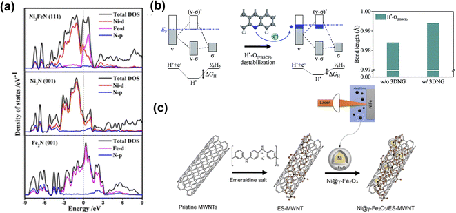 | ||
| Fig. 13 Metal and carbonaceous materials interface for OER electrocatalysts. (a) Total and partial electronic density of states (TDOS and PDOS) calculated for Ni3FeN (111), Ni3N (001), and Fe2N (001).149 Copyright 2018. American Chemical Society. (b) Bonding scheme of H*–O(PBSCF) and corresponding ΔGH (left), and the bond length of H*–O(PBSCF) without and with 3DNG (right).150 Copyright 2019. The Royal Society of Chemistry. (c) Schematic illustration for the synthesis of the Ni@γ-Fe2O3 NPs and the Ni@γ-Fe2O3/ES-MWNT hybrid materials.153 Copyright 2018. American Chemical Society. | ||
In heterostructured electrocatalysts, the interface effect can efficiently optimize the electron transfer and enhance the electrochemical performance by (a) lowering the interfacial resistance and adsorption energy of oxygen, (b) improving the electron-withdrawing ability and creating the metal–oxygen interface, and (c) boosting synergy between compositions through unique reaction steps.
3.5. Strain engineering
In recent years, strain engineering for nanostructures has gained attention in electrochemical reactions including OER, HER, alcohol oxidation reactions, CO2 reduction, and N2 reduction reactions. Strain is the deformation of a solid caused by stress and is a dimensionless quantity. Experimental and theoretical studies have suggested that creating strain in materials can successfully modulate the electronic structure.159 Thus, introducing strain is a viable technique for altering the electronic structure and boosting the electrocatalytic activity of nanomaterials. Since electronic structure modulation is closely tied to the d-band center of a material and thus the performance in electrocatalytic processes like OER, numerous reports exist with regard to how the d-band center position relative to the Fermi level is altered under applied strain, as shown in Fig. 14a and b.160 When tensile or compressive strain is applied to transition metals (more than half-filled d-band), the d-orbital overlap changes accordingly, giving rise to a sharpening of the d-band and a shift in its d-band center to preserve the degree of d-band filling. As the electrochemical performance of a material directly correlates to its electronic structure, it can, therefore, be effectively tuned by strain engineering. Various methods have been used to generate strain in the catalysts including epitaxial growth of thin films,161,162 formation of bimetallic nanoparticles163 and crystal morphology engineering.164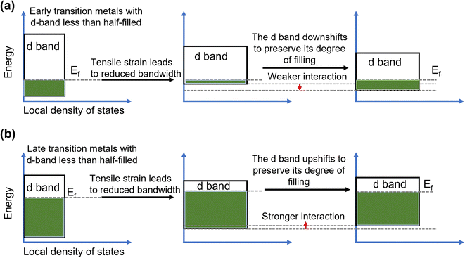 | ||
| Fig. 14 Mechanism of strain enhanced OER. Energy diagrams showing the influence of (a) tensile and (b) compressive strain on the d band of early transition metals.163 Copyright 2019. Springer Nature. | ||
Through first-principles calculations, Yildiz and co-workers165 showed a planar strain effect on the oxygen-vacancy formation and oxygen adsorption in LaCo3. The adsorption of oxygen molecules transitioned from chemisorption to physisorption at high strain. Adjusting with charge-density profiles, the density of electronic states, and stress threshold, they proposed the possibility of tuning strain-mediated reactivity in LaCo3 and other related perovskites. Later, several studies explored the effect of strain on surface reactivity. Koper and co-workers34 developed electrocatalysts based on iridium double perovskites (Ir DPs), which contain 32 wt% less iridium than IrO2 and yet exhibit more than threefold higher activity in acid electrolyte. Double perovskites (DPs) have a general formula of A2BB'O6, where A denotes a large cation and B and B′ smaller cations. Fig. 15a shows the crystal structure of an ideal DP. The high catalytic activity of Ir DPs is thought to be due to the crystal lattice strain caused by the small Lanthanide and Yttrium cations in the B′ site of the DPs. As IrO2 and oxygen bind strongly, the lattice strain caused by the substitution of smaller lanthanides or yttrium weakens the oxygen adsorption energy and therefore improves the activity of the Ir DPs in comparison to IrO2.
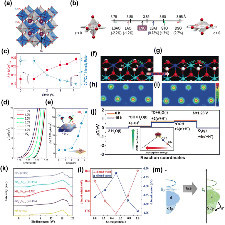 | ||
| Fig. 15 Performance and computational studies of strain engineered OER electrocatalysts. (a) Crystal structure of a generic Ba2MIrO6 DP.34 Copyright 2016. Springer Nature. (b) Lattice parameters and associated biaxial strain for LNO on various substrates.162 Copyright 2016. American Chemical Society. (c) Plot of the ratio of the intensities of the Co4+ and Co3+ peaks showing a clear trend toward decreasing Co valency with tensile strain, with a matching trend in oxygen non-stoichiometry (δ). A strain-relaxed P-SCO film on LSAO (ε = 0%) was used. (d) Polarization curves for the OER reaction on P-SCO under increasing amounts of biaxial tensile strain. (e) Current densities at 1.6 V vs. RHE for all of the films are plotted as a function of strain. The activity for a textured (111) IrO2 film is included. Theoretical calculations of OER catalysis on NiFe-LDH with and without ball-milling treatment.167 Copyright 2016. American Chemical Society. (f and g) Slab model. (h and i) Electron density distribution. (j) Free energy profile.168 Copyright 2019. Wiley-VCH. (k) UPS of samples. (l) The d-band center and corresponding d-bandwidth of the NiSxSe1−x surface. (m) Schematic of the electron exchange for the lattice-strained surface.169 Copyright 2020. Wiley-VCH. | ||
In another example, an n-doped rutile TiO2 film is directly grown on NiTi foil, and its catalytic performance was examined after applying tensile strain.166 The tensile strain increased the density of surface accessible sites and lowered the activation barrier in the reaction pathway. Stoerzinger et al.161 demonstrated that epitaxial strain via lattice mismatch could tune the activity of oxygen electrocatalysis of LaCoO3 in alkaline solutions. The moderate tensile strain can further induce changes in the electronic structure leading to an enhanced electrocatalytic performance by LaCoO3. Lee and co-workers162 systematically determined the effect of epitaxial strain on the conducting perovskite LaNiO3. They used epitaxially strained LaNiO3 ranging from tensile (+) to compressive (−) to check its influence on OER over a range of lattice-mismatched substrates, which included (001) LaSrAlO4 (LSAO), (001) LaAlO3 (LAO), (001) (LaAlO3)0.3(SrAl0.5Ta0.5O3)0.7 (LSAT), (001) SrTiO3 (STO), and (001)pc DyScO3 (DSO) (Fig. 15b). The results suggest that moderate tensile strain can induce change in electronic structure, leading to enhanced electrochemical OER performance. The same group also used a perovskite-based strontium cobaltite (P-SCO) thin film to show that epitaxial strain could tune the oxygen stoichiometry under conditions consistent with the OER.167 The epitaxial strain regulates the oxygen vacancies and Co4+/Co3+ ratio in P-SCO film (Fig. 15c). The P-SCO film with 4.2% strain matches electrocatalytic activity with noble-metal IrO2 catalyst (Fig. 15d and e).
Liu and co-workers168 used a facile ball-milling method to improve the binding strength of NiFe-LDH to oxygenated intermediates via generated tensile strain, which reduced the anti-bonding filling states in the d orbitals and thus facilitated the adsorption of oxygenated intermediates. DFT calculations gave further insight into the relation between lattice strain and OER kinetics. Fig. 15f and g shows the stretched Ni–O and Fe–O (stretched by 0.16 Å) to simulate the ball-milled NiFe-LDH. Fig. 15h and i compare the electron densities around the Ni and Fe sites in NiFe-LDH, which clearly show the electron-rich structure of NiFe-LDH with tensile strain. The calculated OER (Fig. 15j) overpotential decreases from 0.55 to 0.48 eV and Gibbs free energy for every elementary step is optimized after introducing tensile strain in NiFe-LDH. This is believed to be due to the enhanced adsorption for oxygenated intermediates, which moves NiFe-LDH towards the vertex of the activity volcano (inset in Fig. 15j).
Deng and co-workers169 prepared NiSxSe1−x nanorods@nanosheets hybrids (NiSxSe1−x NNH) on Ni foam (NF) and induced the strain-effect both on the surface and in the interior of the materials. The results showed dramatic improvement in electrochemical performance. It was suggested that NiS0.5Se0.5 electrocatalyst with ≈2.7% lattice strain exhibits the best oxygen evolution reaction (OER) performance with low overpotentials of 257 mV at 10 mA cm−2, with long-term stability for 300 h at 10 and even 100 mA cm−2. The NiS0.5Se0.5 has a lower work function and high Fermi level compared to other samples, as shown in Fig. 15k, which verify that the NiS0.5Se0.5 possesses the highest electrical conductivity. Also, with an increase in lattice strain, the d-band width decreases, with the d-band of the composite shifting closer to the Fermi level (Fig. 15l). Evidently the generated strain narrowed the bandwidth and thus influences the electronic structure of the material. With an upshift of the d-band center, the adsorption interaction with the reaction intermediates is improved, thus fostering enhanced activity (Fig. 15m).
Recently, Yan and coworkers170 proposed a facile strategy to introduce lattice strain in the metal–organic framework (MOF). They employed monocarboxylic acid as the linker scission to replace part of binary carboxylic acid in NiFe-MOF. The as-prepared lattice-strained NiFe-MOF exhibited superior OER performance with 230 mV overpotential to reach 10 mA cm−2 in alkaline electrolyte. Using the XAS and synchrotron radiation Fourier transform infrared spectroscopy (SR-FTIR) studies, it was observed that during OER the key *OOH intermediate was adsorbed on high-valence Ni3+/4+ sites. This suggests Ni3+/4+ sites were the most active sites for OER in which the rate-limiting step is the formation of *OOH. First-principles study indicates that the electronic structure of Ni active sites in MOFs can be modulated by lattice strain, enhancing the OER performance of NiFe-MOFs.
4. Characterization of electrocatalysts
Understanding the structure of the electrocatalyst using characterization helps to elucidate the relationship between structure and the physical and electrochemical properties. Herein, we have summarized some quantitative and qualitative characterization techniques. Powder X-ray Diffraction (PXRD) and Electron Microscopy (EM) are the most commonly utilized tools to glean basic information about changes in a material when it undergoes electronic structure modulations. In particular, advanced aberration-corrected transmission electron microscopy (ACTEM) can be used to characterize defects such as oxygen and sulfur vacancies.171,172 Yao and coworkers173 used ACTEM analysis to visualize the defect regions of materials (Fig. 16a). XPS can be used to analyze surface chemical states and gather other electronic information. Recently, Gao et al. verified oxygen vacancies in NiFe LDH by analyzing the O1s XPS spectrum.174 Electron paramagnetic resonance (EPR) spectroscopy is commonly used to elucidate oxygen vacancies in nanomaterials.175 For example, Xiao et al.176 used EPR to prove the existence of oxygen vacancies in electrocatalysts. As shown in Fig. 16b, the EPR signal peak at g = 2.003 indicates the electrons have been captured by the defects, confirming the existence of free electrons trapped in oxygen vacancies. With the rapid development of synchrotron radiation sources, X-ray absorption spectroscopy (XAS) techniques including extended X-ray absorption fine structure (EXAFS) and X-ray absorption near edge structure (XANES) analysis have become an invaluable and effective characterization method to check the changes in the electronic structure around the active center.177 Zhang et al.178 used XANES and EXAFS to explore the defects in ultrafine monolayer NiFe LDH structure (LDH-UF). The EXAFS data conclusively suggests the existence of multivacancies (oxygen, Ni, and Fe vacancies) in LDH-UF. The presence of these vacancies dramatically alters the LDH electronic structure and electrochemical properties (Fig. 16c–h).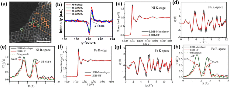 | ||
| Fig. 16 Characterizations employed for the elucidation of structural imperfections and resultant alterations of the electronic structure (a) HAADF image of DG with an acceleration voltage of 80 kV. Hexagons, pentagons, heptagons, and octagons were labeled in orange, green, blue, and red, respectively.173 Copyright 2016. Wiley-VCH (b) EPR of AP-CoMoO4 and n-CoMoO4.176 Copyright 2022. Wiley-VCH (c) (A) Ni K-edge XANES spectra, (d) Ni K-edge EXAFS oscillation functions k2χ (k), and (e) magnitude of k2-weighted FT of the Ni K-edge EXAFS spectra. (f) Fe K-edge XANES spectra, (g) Fe K-edge EXAFS oscillation functions k2χ (k), and (h) magnitude of k2-weighted FT of the Fe K-edge EXAFS spectra for LDH-Monolayer and LDH-UF, respectively.178 Copyright 2018. Wiley-VCH. | ||
5. Conclusion and outlook
The design and development of an efficient OER electrocatalyst for water splitting carries great significance. This article has outlined the recent research efforts on electronic structure modulation of electrocatalysts, including transition-metal-based nanomaterials, noble metals, and perovskite oxides for the OER. Key strategies for tuning the electronic structure of the electrocatalyst, such as alloying, doping, creating oxygen vacancies, heterostructure engineering, and strain engineering, are introduced, and their effect in enhancing the OER performance are discussed. Through these discussions, it is clear that electronic structure modification is the most effective method for improving electrochemical performance (Table 1). Although significant research progress has been made, many significant challenges continue to exist and require careful design and analysis. Going forward, here are a few, although not exhaustive, suggestions that researchers can keep in mind in the search for more efficient OER catalysts:| Electrocatalyst | Strategy | Overpotential (mV) at 10 mA cm−2 | Reference |
|---|---|---|---|
| Mo-NiCo2O4/Co5.47N/NF | Doping | 370 | 184 |
| Ru-RuPx-CoxP | Doping | 291 | 185 |
| Ni3P:FeMo | Doping | 250 | 23 |
| NiVIr-LDH | Doping | 180 | 186 |
| N-CoFe LDHs | Doping | 281 | 65 |
| Co/Ce-Ni3S2/NF | Doping | 286 @ 20 mA cm−2 | 77 |
| Ru/Ni-Co3O4 | Doping | 290 | 78 |
| Co, Nb-MoS2/TiO2 HSs | Doping | 260 | 80 |
| Defect-rich Co3O4 nanosheets | Oxygen vacancy | 200 | 89 |
| Fe1Co1-ONS | Oxygen vacancy | 308 | 92 |
| PrBaCo2O5.75 | Oxygen vacancy | 360 | 95 |
| CoFe LDHs nanosheets | Oxygen vacancy | 232 | 98 |
| NiFe-LDH | Oxygen vacancy | 310 | 99 |
| Co3O4−x | Oxygen vacancy | 330 | 100 |
| Plasma-engraved Co3O4 nanosheets | Oxygen vacancy | 300 | 85 |
| Vo-MnCo2O4 | Oxygen vacancy | 400 | 102 |
| La1−xCoO3−δ (x = 0.3) | Oxygen vacancy | 326 | 103 |
| NiFe-LDH | Oxygen vacancy | 250 | 117 |
| Co3O4 | Oxygen vacancy | 298 | 119 |
| Ir3Ni2/BMNC | Alloying | 279 | 130 |
| Ni0.93Ir0.07/rGO | Alloying | 271.8 | 131 |
RuCu NSs/C-350![[thin space (1/6-em)]](https://www.rsc.org/images/entities/char_2009.gif) °C °C |
Alloying | 234 | 132 |
| e-Ni0.6Ru0.4@C | Alloying | 278 @ 100 mA cm−2 | 133 |
| FeIr/NF | Alloying | 200 @ 20 mA cm−2 | 135 |
| Fe60(CoNi)30Cr10 | Alloying | 187 | 187 |
| NiCoFeMoMn high-entropy alloy | Alloying | 350 @ 1000 mA cm−2 | 188 |
| NiMoOx/NiMoS | Heterostructure | 186 | 144 |
| Co3Mo/CoMoOx | Heterostructure | 256 | 145 |
| CoSe2@MoSe2 | Heterostructure | 309 | 189 |
| Co3O4@Mo-Co3S4-Ni3S2/NF | Heterostructure | 295 @ 50 mA cm−2 | 190 |
| CoP-FeP | Heterostructure | 250 | 148 |
| Co@CoP2/CF | Heterostructure | 210 | 191 |
| WO2-Ni17W3/NiFe(OH)x | Heterostructure | 240 @ 50 mA cm−2 | 192 |
| NiSe@CoFe LDH | Heterostructure | 203 | 193 |
| NiCo2Px/CNTs | Heterostructure | 284 | 152 |
| CoFe-OH@FeOOH | Heterostructure | 200 | 194 |
| NiFe-LDH | Strain engineering | 270 | 168 |
| NiSxSe1−x NNH | Strain engineering | 257 | 169 |
| Na0.7CoO2-Ag | Strain engineering | 236 | 195 |
| Ni3Al alloy | Strain engineering | 280 | 196 |
| Co@N1-GY | Strain engineering | 330 | 197 |
| Co2P/Ni2P-2% Mo | Strain engineering | 319 @ 50 mA cm−2 | 198 |
| Ni3FeN/Ni3Fe | Strain engineering | 250 | 199 |
| Ru-ZnIn2S4 | Strain engineering | 276 @ 50 mA cm−2 | 200 |
| NiFe-MOF | Strain engineering | 300 mV | 201 |
(a) While taking into account the most popular strategies that have been documented in this paper, new ground must be explored such as combinatorial versions of established methods. Using a combination of alloying and interface engineering, Liu et al.179 demonstrated an NiFe(OH)x/(Ni,Fe)Se2/CC catalyst that showed far superior OER performance to typically reported NiFe(OH)x catalysts, whose OER performance is impeded by poor electrical conductivity. Without further doping, the Xie group demonstrated a dual modulation strategy wherein electrochemical reduction activation generated poorly crystalline CoO islands interfaced with highly crystalline Co3O4 nanowires.180 This led to the generation of the key active component oxygen-vacancy rich CoOOH layer responsible for a 10-fold OER performance enhanced compared to pristine Co3O4. Doping metal atoms into alloys to further enhance their OER performance has also been documented and is a domain that should be pursued by prospective researchers. Qiao et al.181 recently reported Fe-doped intermetallic Co2B, which demonstrated OER activity surpassing that of IrO2.
(b) During electrochemical measurements, the vacancies, strain, and heterostructure interfaces can change over time. The ex situ or conventional characterizations may not reflect the active catalytic centers. Significant advances in in situ spectroscopic techniques (e.g., in situ Fourier-transform infrared spectroscopy and in situ Raman spectroscopy, and in situ XAS) as well as time-resolved measurements have shown promise in providing in-depth insight into electrocatalytic behaviour. These in situ characterizations could provide real-time information on potential structural changes, chemical states, and reaction mechanisms under varying electrochemical measurement conditions. The results will be helpful to improve the performance and stability of electrocatalysts and binding trends along with parameters for databases. Ongoing efforts to gather data from numerous experiments have since enhanced theoretical calculations too.182
(c) The experimental characterizations suggest that the electrocatalysts go through chemical and physical changes during OER. Hence, relying on theoretical models to predict the behavior of an electrocatalytic material is a path that more researchers should consider adopting.183 Current advances in first principles-based studies can provide insight into morphological or structural changes a material will undergo in various electrochemical environments, even if these studies are not exhaustive. All the electronic structure modulation strategies covered in this review lend themselves to effective scrutiny via modern theoretical tools. Researchers can consider using these existing analyses to design their catalytic materials.
In summary, targeted analysis should focus on designing efficient, stable, and scalable electrocatalysts for OER. Such approaches will allow enhancements in the capabilities of new electrocatalysts, through continuous efforts on the electronic structure modulation-based material design. Improved synthetic strategies will enable the development of promising electrocatalysts to usher in a greener energy economy facilitated by efficient water splitting.
Conflicts of interest
There are no conflicts to declare.Acknowledgements
This work is supported by the King Abdullah University of Science and Technology (KAUST).References
- N. S. Lewis, Science, 2016, 351, aad1920 CrossRef
.
- H. Tao, Q. Fan, T. Ma, S. Liu, H. Gysling, J. Texter, F. Guo and Z. Sun, Prog. Mater. Sci., 2020, 111, 100637 CrossRef CAS
.
- J. A. Turner, Science, 2004, 305, 972–974 CrossRef CAS PubMed
.
- I. Roger, M. A. Shipman and M. D. Symes, Nat. Rev. Chem., 2017, 1, 0003 CrossRef CAS
.
- J. H. Montoya, L. C. Seitz, P. Chakthranont, A. Vojvodic, T. F. Jaramillo and J. K. Nørskov, Nat. Mater., 2017, 16, 70–81 CrossRef PubMed
.
- K. Zhu, F. Shi, X. Zhu and W. Yang, Nano Energy, 2020, 73, 104761 CrossRef CAS
.
- Y.-R. Zheng, J. Vernieres, Z. Wang, K. Zhang, D. Hochfilzer, K. Krempl, T.-W. Liao, F. Presel, T. Altantzis, J. Fatermans, S. B. Scott, N. M. Secher, C. Moon, P. Liu, S. Bals, S. Van Aert, A. Cao, M. Anand, J. K. Nørskov, J. Kibsgaard and I. Chorkendorff, Nat. Energy, 2022, 7, 55–64 CrossRef CAS
.
- M. G. Walter, E. L. Warren, J. R. McKone, S. W. Boettcher, Q. Mi, E. A. Santori and N. S. Lewis, Chem. Rev., 2010, 110, 6446–6473 CrossRef CAS PubMed
.
- D. H. Kweon, M. S. Okyay, S.-J. Kim, J.-P. Jeon, H.-J. Noh, N. Park, J. Mahmood and J.-B. Baek, Nat. Commun., 2020, 11, 1278 CrossRef CAS PubMed
.
- S. Y. Bae, J. Mahmood, I. Y. Jeon and J. B. Baek, Nanoscale Horiz., 2019, 5, 43–56 RSC
.
- A. N. Rollinson, J. Jones, V. Dupont and M. V. Twigg, Energy Environ. Sci., 2011, 4, 1216 RSC
.
- A.-L. Wang, H. Xu and G.-R. Li, ACS Energy Lett., 2016, 1, 445–453 CrossRef CAS
.
- R. Souleymen, Z. Wang, C. Qiao, M. Naveed and C. Cao, J. Mater. Chem. A, 2018, 6, 7592–7607 RSC
.
- S. Z. Oener, L. P. Twight, G. A. Lindquist and S. W. Boettcher, ACS Energy Lett., 2021, 6, 1–8 CrossRef CAS
.
- X. Zou and Y. Zhang, Chem. Soc. Rev., 2015, 44, 5148–5180 RSC
.
- C. Z. Yuan, K. S. Hui, H. Yin, S. Zhu, J. Zhang, X. L. Wu, X. Hong, W. Zhou, X. Fan, F. Bin, F. Chen and K. N. Hui, ACS Mater. Lett., 2021, 3, 752–780 CrossRef CAS
.
- S. Rafai, C. Qiao, Z. Wang, C. Cao, T. Mahmood, M. Naveed, W. Younas and S. Khalid, ChemElectroChem, 2019, 6, 5469–5478 CrossRef CAS
.
- S. Anantharaj, S. Kundu and S. Noda, Nano Energy, 2021, 80, 105514 CrossRef CAS
.
- P. Babar, A. Lokhande, H. H. Shin, B. Pawar, M. G. Gang, S. Pawar and J. H. Kim, Small, 2018, 14, 1702568 CrossRef PubMed
.
- P. Babar, A. Lokhande, V. Karade, I. J. Lee, D. Lee, S. Pawar and J. H. Kim, J. Colloid Interface Sci., 2019, 557, 10–17 CrossRef CAS
.
- S. Z. Oener, M. J. Foster and S. W. Boettcher, Science, 2020, 369, 1099–1103 CrossRef CAS PubMed
.
- P. Babar, K. Patil, V. Karade, K. Gour, A. Lokhande, S. Pawar and J. H. Kim, ACS Appl. Mater. Interfaces, 2021, 13, 52620–52628 CrossRef CAS
.
- S. M. Pawar, A. T. Aqueel Ahmed, C. H. Lee, P. T. Babar, J. H. Kim, S. U. Lee, H. Kim and H. Im, ACS Appl. Energy Mater., 2021, 4, 14169–14179 CrossRef CAS
.
- N. Mushtaq, Z. Wang, H. Tabassum, M. Tahir, Z. Han, Y. Zhu, W. Younas, X. Ma and C. Cao, Dalt. Trans., 2022, 51, 6285–6292 RSC
.
- J. S. Kim, B. Kim, H. Kim and K. Kang, Adv. Energy Mater., 2018, 8, 1702774 CrossRef
.
- P. T. Babar, A. C. Lokhande, M. G. Gang, B. S. Pawar, S. M. Pawar and J. H. Kim, J. Ind. Eng. Chem., 2018, 60, 493–497 CrossRef CAS
.
- Y. Yan, B. Y. Xia, B. Zhao and X. Wang, J. Mater. Chem. A, 2016, 4, 17587–17603 RSC
.
- P. T. Babar, A. C. Lokhande, B. S. Pawar, M. G. Gang, E. Jo, C. Go, M. P. Suryawanshi, S. M. Pawar and J. H. Kim, Appl. Surf. Sci., 2018, 427, 253–259 CrossRef CAS
.
- H. Boumeriame, E. S. Da Silva, A. S. Cherevan, T. Chafik, J. L. Faria and D. Eder, J. Energy Chem., 2022, 64, 406–431 CrossRef
.
- K. Patil, P. Babar, D. M. Lee, V. Karade, E. Jo, S. Korade and J. H. Kim, Sustain. Energy Fuels, 2020, 4, 5254–5263 RSC
.
- S. Anantharaj, S. R. Ede, K. Sakthikumar, K. Karthick, S. Mishra and S. Kundu, ACS Catal., 2016, 6, 8069–8097 CrossRef CAS
.
- N. Han, P. Liu, J. Jiang, L. Ai, Z. Shao and S. Liu, J. Mater. Chem. A, 2018, 6, 19912–19933 RSC
.
- R. Khan, M. T. Mehran, S. R. Naqvi, A. H. Khoja, K. Mahmood, F. Shahzad and S. Hussain, Int. J. Energy Res., 2020, 44, 9714–9747 CrossRef CAS
.
- O. Diaz-Morales, S. Raaijman, R. Kortlever, P. J. Kooyman, T. Wezendonk, J. Gascon, W. T. Fu and M. T. M. Koper, Nat. Commun., 2016, 7, 12363 CrossRef CAS PubMed
.
- C. Qiao, Z. Usman, T. Cao, S. Rafai, Z. Wang, Y. Zhu, C. Cao and J. Zhang, Chem. Eng. J., 2021, 426, 130873 CrossRef CAS
.
- C. Qiao, S. Rafai, T. Cao, Z. Wang, H. Wang, Y. Zhu, X. Ma, P. Xu and C. Cao, ChemCatChem, 2020, 12, 2823–2832 CrossRef CAS
.
- L. Li, P. Wang, Q. Shao and X. Huang, Chem. Soc. Rev., 2020, 49, 3072–3106 RSC
.
- J. He, Y. Zou and S. Wang, Dalt. Trans., 2018, 48, 15–20 RSC
.
- N. Mushtaq, C. Qiao, H. Tabassum, M. Naveed, M. Tahir, Y. Zhu, M. Naeem, W. Younas and C. Cao, Sustain. Energy Fuels, 2020, 4, 5294–5300 RSC
.
- D. Zhou, P. Li, X. Lin, A. McKinley, Y. Kuang, W. Liu, W. F. Lin, X. Sun and X. Duan, Chem. Soc. Rev., 2021, 50, 8790–8817 RSC
.
- Z.-P. Wu, F. Lu, S.-Q. Zang, X. Wen, D. Lou, Z.-P. Wu, X. F. Lu, X. W. Lou and S.-Q. Zang, Adv. Funct. Mater., 2020, 30, 1910274 CrossRef CAS
.
- Q. Pan and L. Wang, J. Power Sources, 2021, 485, 229335 CrossRef CAS
.
- C. Feng, M. B. Faheem, J. Fu, Y. Xiao, C. Li and Y. Li, ACS Catal., 2020, 10, 4019–4047 CrossRef CAS
.
- K. Zeng, X. Zheng, C. Li, J. Yan, J.-H. Tian, C. Jin, P. Strasser, R. Yang, K. Zeng, X. J. Zheng, C. Li, J. Yan, J. Tian, C. Jin, R. Z. Yang and P. Strasser, Adv. Funct. Mater., 2020, 30, 2000503 CrossRef CAS
.
- H. Dau, C. Limberg, T. Reier, M. Risch, S. Roggan and P. Strasser, ChemCatChem, 2010, 2, 724–761 CrossRef CAS
.
- F. Lu, M. Zhou, Y. Zhou, X. Zeng, F. Lu, M. Zhou, Y. Zhou and X. Zeng, Small, 2017, 13, 1701931 CrossRef PubMed
.
- H. Dau, C. Limberg, T. Reier, M. Risch, S. Roggan and P. Strasser, ChemCatChem, 2010, 2, 724–761 CrossRef CAS
.
- R. Gao and D. Yan, Adv. Energy Mater., 2020, 10, 1900954 CrossRef CAS
.
- L. Trotochaud, S. L. Young, J. K. Ranney and S. W. Boettcher, J. Am. Chem. Soc., 2014, 136, 6744–6753 CrossRef CAS PubMed
.
- D. Friebel, M. W. Louie, M. Bajdich, K. E. Sanwald, Y. Cai, A. M. Wise, M.-J. Cheng, D. Sokaras, T.-C. Weng, R. Alonso-Mori, R. C. Davis, J. R. Bargar, J. K. Nørskov, A. Nilsson and A. T. Bell, J. Am. Chem. Soc., 2015, 137, 1305–1313 CrossRef CAS PubMed
.
- J. Jiang, F. Sun, S. Zhou, W. Hu, H. Zhang, J. Dong, Z. Jiang, J. Zhao, J. Li, W. Yan and M. Wang, Nat. Commun., 2018, 9, 2885 CrossRef PubMed
.
- J. Chen, M. Gu, S. Liu, T. Sheng and X. Zhang, ACS Appl. Mater. Interfaces, 2021, 13, 16210–16217 CrossRef CAS PubMed
.
- R. Wei, X. Bu, W. Gao, R. A. B. Villaos, G. MacAm, Z. Q. Huang, C. Lan, F. C. Chuang, Y. Qu and J. C. Ho, ACS Appl. Mater. Interfaces, 2019, 11, 33012–33021 CrossRef CAS PubMed
.
- T. Kang, K. Kim, M. Kim and J. Kim, Chem. Eng. J., 2021, 418, 129403 CrossRef CAS
.
- P. Babar, A. Lokhande, V. Karade, B. Pawar, M. G. Gang, S. Pawar and J. H. Kim, ACS Sustainable Chem. Eng., 2019, 7, 10035–10043 CrossRef CAS
.
- D. A. Corrigan, J. Electrochem. Soc., 1987, 134, 377 CrossRef CAS
.
- G. Młynarek, M. Paszkiewicz and A. Radniecka, J. Appl. Electrochem., 1984, 14, 145–149 CrossRef
.
- L. Trotochaud, J. K. Ranney, K. N. Williams and S. W. Boettcher, J. Am. Chem. Soc., 2012, 134, 17253–17261 CrossRef CAS PubMed
.
- Z. Sun, A. Curto, J. Rodríguez-Fernández, Z. Wang, A. Parikh, J. Fester, M. Dong, A. Vojvodic and J. V. Lauritsen, ACS Nano, 2021, 15, 18226–18236 CrossRef CAS
.
- U. I. Kramm, L. Ni and S. Wagner, Adv. Mater., 2019, 31, 1805623 CrossRef
.
- J. Y. C. Chen, L. Dang, H. Liang, W. Bi, J. B. Gerken, S. Jin, E. E. Alp and S. S. Stahl, J. Am. Chem. Soc., 2015, 137, 15090–15093 CrossRef CAS PubMed
.
- M. Görlin, P. Chernev, J. F. de Araújo, T. Reier, S. Dresp, B. Paul, R. Krähnert, H. Dau and P. Strasser, J. Am. Chem. Soc., 2016, 138, 5603–5614 CrossRef PubMed
.
- G. Fu, X. Wen, S. Xi, Z. Chen, W. Li, J.-Y. Zhang, A. Tadich, R. Wu, D.-C. Qi, Y. Du, J. Cheng and K. H. L. Zhang, Chem. Mater., 2018, 31, 419–428 CrossRef
.
- Q. Li, X. Wang, K. Tang, M. Wang, C. Wang and C. Yan, ACS Nano, 2017, 11, 12230–12239 CrossRef CAS PubMed
.
- Y. Wang, C. Xie, Z. Zhang, D. Liu, R. Chen and S. Wang, Adv. Funct. Mater., 2018, 28, 1703363 CrossRef
.
- S. Niu, W.-J. Jiang, Z. Wei, T. Tang, J. Ma, J.-S. Hu and L.-J. Wan, J. Am. Chem. Soc., 2019, 141, 7005–7013 CrossRef CAS PubMed
.
- S. Han, S. Liu, R. Wang, X. Liu, L. Bai and Z. He, ACS Appl. Mater. Interfaces, 2017, 9, 17186–17194 CrossRef CAS PubMed
.
- X. Wu and K. Scott, J. Mater. Chem., 2011, 21, 12344–12351 RSC
.
- B. Chi, H. Lin and J. Li, Int. J. Hydrogen Energy, 2008, 33, 4763–4768 CrossRef CAS
.
- T. W. Kim, M. A. Woo, M. Regis and K.-S. Choi, J. Phys. Chem. Lett., 2014, 5, 2370–2374 CrossRef CAS PubMed
.
- P. W. Menezes, A. Indra, A. Bergmann, P. Chernev, C. Walter, H. Dau, P. Strasser and M. Driess, J. Mater. Chem. A, 2016, 4, 10014–10022 RSC
.
- Y. Zhou, S. Sun, J. Song, S. Xi, B. Chen, Y. Du, A. C. Fisher, F. Cheng, X. Wang, H. Zhang and Z. J. Xu, Adv. Mater., 2018, 30, 1802912 CrossRef
.
- Y. Zhang, C. Wu, H. Jiang, Y. Lin, H. Liu, Q. He, S. Chen, T. Duan, L. Song, Y. Zhang, C. Wu, H. Jiang, Y. Lin, H. Liu, Q. He, S. Chen, L. Song and T. Duan, Adv. Mater., 2018, 30, 1707522 CrossRef PubMed
.
- S. K. Bikkarolla and P. Papakonstantinou, J. Power Sources, 2015, 281, 243–251 CrossRef CAS
.
- Y. Peng, H. Hajiyani and R. Pentcheva, ACS Catal., 2021, 11, 5601–5613 CrossRef CAS
.
- M. Cui, X. Ding, X. Huang, Z. Shen, T.-L. Lee, F. E. Oropeza, J. P. Hofmann, E. J. M. Hensen and K. H. L. Zhang, Chem. Mater., 2019, 31, 7618–7625 CrossRef CAS
.
- X. Wu, T. Zhang, J. Wei, P. Feng, X. Yan and Y. Tang, Nano Res., 2020, 13, 2130–2135 CrossRef CAS
.
- B. Guo, R. Ma, Z. Li, J. Luo, M. Yang and J. Wang, Mater. Chem. Front., 2020, 4, 1390–1396 RSC
.
- Y. Song, J. Cheng, J. Liu, Q. Ye, X. Gao, J. Lu and Y. Cheng, Appl. Catal., B, 2021, 298, 120488 CrossRef CAS
.
- D. C. Nguyen, T. L. Luyen Doan, S. Prabhakaran, D. T. Tran, D. H. Kim, J. H. Lee and N. H. Kim, Nano Energy, 2021, 82, 105750 CrossRef CAS
.
- J. Qi, H. Wang, J. Lin, C. Li, X. Si, J. Cao, Z. Zhong and J. Feng, J. Colloid Interface Sci., 2019, 557, 28–33 CrossRef CAS
.
- H. Sun, Y. Zhao, K. Mølhave, M. Zhang and J. Zhang, Nanoscale, 2017, 9, 14431–14441 RSC
.
- K. L. Yan, X. Shang, Z. Z. Liu, B. Dong, S. S. Lu, J. Q. Chi, W. K. Gao, Y. M. Chai and C. G. Liu, Int. J. Hydrogen Energy, 2017, 42, 24150–24158 CrossRef CAS
.
- Q. Li, S. Li, O. Ajouyed, C. Chen, Y. Zhou, C. Li, S. Niu, H. Yi, J. Huo and S. Wang, J. Alloys Compd., 2020, 816, 152610 CrossRef CAS
.
- L. Xu, Q. Jiang, Z. Xiao, X. Li, J. Huo, S. Wang and L. Dai, Angew. Chem., Int. Ed., 2016, 55, 5277–5281 CrossRef CAS PubMed
.
- J. Sun, N. Guo, Z. Shao, K. Huang, Y. Li, F. He and Q. Wang, Adv. Energy Mater., 2018, 8, 1800980 CrossRef
.
- M. Xing, W. Fang, M. Nasir, Y. Ma, J. Zhang and M. Anpo, J. Catal., 2013, 297, 236–243 CrossRef CAS
.
- Y. Wang, T. Zhou, K. Jiang, P. Da, Z. Peng, J. Tang, B. Kong, W.-B. Cai, Z. Yang and G. Zheng, Adv. Energy Mater., 2014, 4, 1400696 CrossRef
.
- Z. Cai, Y. Bi, E. Hu, W. Liu, N. Dwarica, Y. Tian, X. Li, Y. Kuang, Y. Li, X.-Q. Yang, H. Wang and X. Sun, Adv. Energy Mater., 2018, 8, 1701694 CrossRef
.
- S. Peng, F. Gong, L. Li, D. Yu, D. Ji, T. Zhang, Z. Hu, Z. Zhang, S. Chou, Y. Du and S. Ramakrishna, J. Am. Chem. Soc., 2018, 140, 13644–13653 CrossRef CAS
.
- M. Asnavandi, Y. Yin, Y. Li, C. Sun and C. Zhao, ACS Energy Lett., 2018, 3, 1515–1520 CrossRef CAS
.
- L. Zhuang, L. Ge, Y. Yang, M. Li, Y. Jia, X. Yao and Z. Zhu, Adv. Mater., 2017, 29, 1606793 CrossRef PubMed
.
- J. Bao, X. Zhang, B. Fan, J. Zhang, M. Zhou, W. Yang, X. Hu, H. Wang, B. Pan and Y. Xie, Angew. Chem., Int. Ed., 2015, 54, 7399–7404 CrossRef CAS PubMed
.
- F. Cheng, T. Zhang, Y. Zhang, J. Du, X. Han and J. Chen, Angew. Chem., Int. Ed., 2013, 52, 2474–2477 CrossRef CAS
.
- X. Miao, L. Wu, Y. Lin, X. Yuan, J. Zhao, W. Yan, S. Zhou and L. Shi, Chem. Commun., 2019, 55, 1442–1445 RSC
.
- Z. Wang, Y. Zhang, E. C. Neyts, X. Cao, X. Zhang, B. W.-L. Jang and C. Liu, ACS Catal., 2018, 8, 2093–2110 CrossRef CAS
.
- M. X. Lin, F. Shao, S. Weng, S. Xiong, S. Liu, S. Jiang, Y. Xu, Y. Jiao and J. Chen, Electrochim. Acta, 2021, 378, 138147 CrossRef CAS
.
- R. Liu, Y. Wang, D. Liu, Y. Zou and S. Wang, Adv. Mater., 2017, 29, 1701546 CrossRef PubMed
.
- H. Chen, Q. Zhao, L. Gao, J. Ran and Y. Hou, ACS Sustainable Chem. Eng., 2019, 7, 4247–4254 CrossRef CAS
.
- L. Ma, S. Chen, Z. Pei, H. Li, Z. Wang, Z. Liu, Z. Tang, J. A. Zapien and C. Zhi, ACS Nano, 2018, 12, 8597–8605 CrossRef CAS PubMed
.
- L. Xu, Z. Wang, J. Wang, Z. Xiao, X. Huang, Z. Liu and S. Wang, Nanotechnology, 2017, 28, 165402 CrossRef
.
- K. Zeng, W. Li, Y. Zhou, Z. Sun, C. Lu, J. Yan, J. H. Choi and R. Yang, Chem. Eng. J., 2021, 421, 127831 CrossRef CAS
.
- Y. Lu, A. Ma, Y. Yu, R. Tan, C. Liu, P. Zhang, D. Liu and J. Gui, ACS Sustainable Chem. Eng., 2018, 7, 2906–2910 CrossRef
.
- Y. Zhang, B. Ouyang, J. Xu, G. Jia, S. Chen, R. S. Rawat and H. J. Fan, Angew. Chem., Int. Ed., 2016, 55, 8670–8674 CrossRef CAS PubMed
.
- Y. Liu, M. Zhang, D. Hu, R. Li, K. Hu and K. Yan, ACS Appl. Energy Mater., 2019, 2, 1162–1168 CrossRef CAS
.
- C. Lei, W. Li, G. Wang, L. Zhuang, J. Lu and L. Xiao, Chem. Res. Chin. Univ., 2021 3722021, 37, 293–297 Search PubMed
.
- Y. Zhu, X. Zhong, S. Jin, H. Chen, Z. He, Q. Liu and Y. Chen, J. Mater. Chem. A, 2020, 8, 10957–10965 RSC
.
- S. Jin, Y. Zhu, Z. He, H. Chen, X. Liu, F. Li, J. Liu, M. Liu and Y. Chen, Int. J. Hydrogen Energy, 2020, 45, 424–432 CrossRef CAS
.
- X. Wang, L. Zhuang, Y. Jia, H. Liu, X. Yan, L. Zhang, D. Yang, Z. Zhu and X. Yao, Angew. Chem., Int. Ed., 2018, 57, 16421–16425 CrossRef CAS PubMed
.
- W. Xu, Y. Bai and Y. Yin, Adv. Mater., 2018, 30, 1802091 CrossRef
.
- W. Xu, F. Lyu, Y. Bai, A. Gao, J. Feng, Z. Cai and Y. Yin, Nano Energy, 2018, 43, 110–116 CrossRef CAS
.
- G. R. Zhang and B. J. M. Etzold, J. Energy Chem., 2016, 25, 199–207 CrossRef
.
- H. Liu, Y. Liu and J. Li, Phys. Chem. Chem. Phys., 2010, 12, 1685–1697 RSC
.
- J. Sun, N. Guo, Z. Shao, K. Huang, Y. Li, F. He and Q. Wang, Adv. Energy Mater., 2018, 8, 1800980 CrossRef
.
- A. A. Chaugule, V. S. Mane, H. A. Bandal, H. Kim and A. S. Kumbhar, ACS Sustainable Chem. Eng., 2019, 7, 14889–14898 CrossRef CAS
.
- I. S. Cho, M. Logar, C. H. Lee, L. Cai, F. B. Prinz and X. Zheng, Nano Lett., 2013, 14, 24–31 CrossRef PubMed
.
- D. Zhou, X. Xiong, Z. Cai, N. Han, Y. Jia, Q. Xie, X. Duan, T. Xie, X. Zheng, X. Sun and X. Duan, Small Methods, 2018, 2, 1800083 CrossRef
.
- C. Meng, M. Lin, X. Sun, X. Chen, X. Chen, X. Du and Y. Zhou, Chem. Commun., 2019, 55, 2904–2907 RSC
.
- Y. Zhou, C.-K. Dong, L. Han, J. Yang and X.-W. Du, ACS Catal., 2016, 6, 6699–6703 CrossRef CAS
.
- C. Dong, Z.-W. Liu, J.-Y. Liu, W.-C. Wang, L. Cui, R.-C. Luo, H.-L. Guo, X.-L. Zheng, S.-Z. Qiao, X.-W. Du and J. Yang, Small, 2017, 13, 1603903 CrossRef PubMed
.
- J. Lai, W. Niu, R. Luque and G. Xu, Nano Today, 2015, 10, 240–267 CrossRef CAS
.
- M. Zhou, C. Li and J. Fang, Chem. Rev., 2020, 121, 736–795 CrossRef PubMed
.
- F. Pang, Z. Wang, K. Zhang, J. He, W. Zhang, C. Guo and Y. Ding, Nano Energy, 2019, 58, 834–841 CrossRef CAS
.
- W. Luc, C. Collins, S. Wang, H. Xin, K. He, Y. Kang and F. Jiao, J. Am. Chem. Soc., 2017, 139, 1885–1893 CrossRef CAS
.
- T. Reier, Z. Pawolek, S. Cherevko, M. Bruns, T. Jones, D. Teschner, S. Selve, A. Bergmann, H. N. Nong, R. Schlögl, K. J. J. Mayrhofer and P. Strasser, J. Am. Chem. Soc., 2015, 137, 13031–13040 CrossRef CAS PubMed
.
- J. Lim, S. Yang, C. Kim, C.-W. Roh, Y. Kwon, Y.-T. Kim and H. Lee, Chem. Commun., 2016, 52, 5641–5644 RSC
.
- J. Feng, F. Lv, W. Zhang, P. Li, K. Wang, C. Yang, B. Wang, Y. Yang, J. Zhou, F. Lin, G.-C. Wang and S. Guo, Adv. Mater., 2017, 29, 1703798 CrossRef PubMed
.
- Y. Pi, Q. Shao, P. Wang, J. Guo and X. Huang, Adv. Funct. Mater., 2017, 27, 1700886 CrossRef
.
- F. Lv, J. Feng, K. Wang, Z. Dou, W. Zhang, J. Zhou, C. Yang, M. Luo, Y. Yang, Y. Li, P. Gao and S. Guo, ACS Cent. Sci., 2018, 4, 1244–1252 CrossRef CAS PubMed
.
- X. Chen, M. Xu, S. Li, C. Li, X. Sun, S. Mu and J. Yu, Adv. Mater. Interfaces, 2020, 7, 2001145 CrossRef CAS
.
- S. Zhang, X. Zhang, X. Shi, F. Zhou, R. Wang and X. Li, J. Energy Chem., 2020, 49, 166–173 CrossRef
.
- Q. Yao, B. Huang, N. Zhang, M. Sun, Q. Shao and X. Huang, Angew. Chem., Int. Ed., 2019, 58, 13983–13988 CrossRef CAS
.
- Q. Yang, P. Jin, B. Liu, L. Zhao, J. Cai, W. Zhan, S. Zuo, J. Zhang and F. Lai, J. Mater. Chem. A, 2020, 8, 9049–9057 RSC
.
- T. T. H. Hoang and A. A. Gewirth, ACS Catal., 2016, 6, 1159–1164 CrossRef CAS
.
- F. Shen, Y. Wang, G. Qian, W. Chen, W. Jiang, L. Luo and S. Yin, Appl. Catal., B, 2020, 278, 119327 CrossRef CAS
.
- C. Wang, H. Yang, Y. Zhang and Q. Wang, Angew. Chem., Int. Ed., 2019, 58, 6099–6103 CrossRef CAS PubMed
.
- K. Liu, C. Zhang, Y. Sun, G. Zhang, X. Shen, F. Zou, H. Zhang, Z. Wu, E. C. Wegener, C. J. Taubert, J. T. Miller, Z. Peng and Y. Zhu, ACS Nano, 2017, 12, 158–167 CrossRef PubMed
.
- L. Lv, Z. Li, K. H. Xue, Y. Ruan, X. Ao, H. Wan, X. Miao, B. Zhang, J. Jiang, C. Wang and K. Ostrikov, Nano Energy, 2018, 47, 275–284 CrossRef CAS
.
- M. Y. Gao, C. Yang, Q. B. Zhang, J. R. Zeng, X. T. Li, Y. X. Hua, C. Y. Xu and P. Dong, J. Mater. Chem. A, 2017, 5, 5797–5805 RSC
.
- T. Zhang, X. Liu, X. Cui, M. Chen, S. Liu and B. Geng, Adv. Mater. Interfaces, 2018, 5, 1800359 CrossRef
.
- J. Yang, Q. Shao, B. Huang, M. Sun and X. Huang, iScience, 2019, 11, 492–504 CrossRef CAS
.
- W. Cai, R. Chen, H. Yang, H. B. Tao, H.-Y. Wang, J. Gao, W. Liu, S. Liu, S.-F. Hung and B. Liu, Nano Lett., 2020, 20, 4278–4285 CrossRef CAS PubMed
.
- D. Zhao, Y. Pi, Q. Shao, Y. Feng, Y. Zhang and X. Huang, ACS Nano, 2018, 12, 6245–6251 CrossRef CAS PubMed
.
- P. Zhai, Y. Zhang, Y. Wu, J. Gao, B. Zhang, S. Cao, Y. Zhang, Z. Li, L. Sun and J. Hou, Nat. Commun., 2020, 11, 5462 CrossRef CAS PubMed
.
- Y. Liu, Y. Xing, S. Xu, Y. Lu, S. Sun and D. Jiang, Chem. Eng. J., 2021, 133240 Search PubMed
.
- Y. Li, J. Yin, L. An, M. Lu, K. Sun, Y.-Q. Zhao, D. Gao, F. Cheng, P. Xi, Y. Li, J. Yin, L. An, M. Lu, K. Sun, Y. Zhao, D. Gao, P. Xi and F. Cheng, Small, 2018, 14, 1801070 CrossRef PubMed
.
- J. Zhang, T. Wang, D. Pohl, B. Rellinghaus, R. Dong, S. Liu, X. Zhuang and X. Feng, Angew. Chem., 2016, 128, 6814–6819 CrossRef
.
- Z. Niu, C. Qiu, J. Jiang and L. Ai, ACS Sustainable Chem. Eng., 2019, 7, 2335–2342 CrossRef CAS
.
- Y. Gu, S. Chen, J. Ren, Y. A. Jia, C. Chen, S. Komarneni, D. Yang and X. Yao, ACS Nano, 2018, 12, 245–253 CrossRef CAS PubMed
.
- Y. Bu, H. Jang, O. Gwon, S. H. Kim, S. H. Joo, G. Nam, S. Kim, Y. Qin, Q. Zhong, S. K. Kwak, J. Cho and G. Kim, J. Mater. Chem. A, 2019, 7, 2048–2054 RSC
.
- M. Tahir, N. Mahmood, X. Zhang, T. Mahmood, F. K. Butt, I. Aslam, F. Idrees, S. Khalid, I. Shakir, Y. Yan, J. Zou, C. Cao, Y. Hou and S.-V. Berlin, Nano Res., 2015, 8, 3725–3736 CrossRef CAS
.
- C. Huang, T. Ouyang, Y. Zou, N. Li and Z. Q. Liu, J. Mater. Chem. A, 2018, 6, 7420–7427 RSC
.
- F. Davodi, E. Mühlhausen, M. Tavakkoli, J. Sainio, H. Jiang, B. Gökce, G. Marzun and T. Kallio, ACS Appl. Mater. Interfaces, 2018, 10, 31300–31311 CrossRef CAS
.
- X. Bai, Q. Wang and J. Guan, ACS Appl. Nano Mater., 2021, 4, 12663–12671 CrossRef CAS
.
- D. Ye, T. Wu, H. Cao, Y. Wang, B. Liu, S. Zhang and J. Kong, RSC Adv., 2015, 5, 26710–26715 RSC
.
- L. Truong, S. K. Jerng, S. B. Roy, J. H. Jeon, K. Kim, K. Akbar, Y. Yi and S. H. Chun, ACS Sustainable Chem. Eng., 2019, 7, 4625–4630 CrossRef CAS
.
- M. S. Ahmed, B. Choi and Y. B. Kim, Sci. Rep., 2018, 8, 1–10 Search PubMed
.
- H. Liu, C. Y. Xu, Y. Du, F. X. Ma, Y. Li, J. Yu and L. Zhen, Sci. Rep., 2019, 9, 1–10 CrossRef PubMed
.
- F. Li, H. Ai, D. Liu, K. H. Lo and H. Pan, J. Mater. Chem. A, 2021, 9, 17749–17759 RSC
.
- M. Luo and S. Guo, Nat. Rev. Mater., 2017, 2, 17059 CrossRef CAS
.
- K. A. Stoerzinger, W. Seok Choi, H. Jeen, H. N. Lee and Y. Shao-Horn, J. Phys. Chem. Lett., 2015, 6, 487–492 CrossRef CAS PubMed
.
- J. R. Petrie, V. R. Cooper, J. W. Freeland, T. L. Meyer, Z. Zhang, D. A. Lutterman and H. N. Lee, J. Am. Chem. Soc., 2016, 138, 2488–2491 CrossRef CAS
.
- B. You, M. T. Tang, C. Tsai, F. Abild-Pedersen, X. Zheng and H. Li, Adv. Mater., 2019, 31, 1807001 CrossRef PubMed
.
- X. Yang, Y. Wang, X. Tong, N. Yang, X. Yang, Y. Wang, X. Tong and N. Yang, Adv. Energy Mater., 2022, 12, 2102261 CrossRef CAS
.
- A. Kushima, S. Yip and B. Yildiz, Phys. Rev. B: Condens. Matter Mater. Phys., 2010, 82, 115435 CrossRef
.
- E. E. Benson, M. A. Ha, B. A. Gregg, J. van de Lagemaat, N. R. Neale and D. Svedruzic, Sci. Rep., 2019, 9, 1–8 CrossRef CAS PubMed
.
- J. R. Petrie, H. Jeen, S. C. Barron, T. L. Meyer and H. N. Lee, J. Am. Chem. Soc., 2016, 138, 7252–7255 CrossRef CAS PubMed
.
- D. Zhou, S. Wang, Y. Jia, X. Xiong, H. Yang, S. Liu, J. Tang, J. Zhang, D. Liu, L. Zheng, Y. Kuang, X. Sun and B. Liu, Angew. Chem., 2019, 131, 746–750 CrossRef
.
- Y. Wang, X. Li, M. Zhang, Y. Zhou, D. Rao, C. Zhong, J. Zhang, X. Han, W. Hu, Y. Zhang, K. Zaghib, Y. Wang and Y. Deng, Adv. Mater., 2020, 32, 2000231 CrossRef CAS PubMed
.
- Q. Ji, Y. Kong, C. Wang, H. Tan, H. Duan, W. Hu, G. Li, Y. Lu, N. Li, Y. Wang, J. Tian, Z. Qi, Z. Sun, F. Hu and W. Yan, ACS Catal., 2020, 10, 5691–5697 CrossRef CAS
.
- X. Yu, Z. Sun, Z. Yan, B. Xiang, X. Liu and P. Du, J. Mater. Chem. A, 2014, 2, 20823–20831 RSC
.
- Y. Hou, M. Qiu, M. G. Kim, P. Liu, G. Nam, T. Zhang, X. Zhuang, B. Yang, J. Cho, M. Chen, C. Yuan, L. Lei and X. Feng, Nat. Commun., 2019, 10, 1–9 CrossRef CAS PubMed
.
- Y. Jia, L. Zhang, A. Du, G. Gao, J. Chen, X. Yan, C. L. Brown, X. Yao, Y. Jia, L. Z. Zhang, X. C. Yan, X. D. Yao, C. L. Brown, A. J. Du, G. P. Gao and J. Chen, Adv. Mater., 2016, 28, 9532–9538 CrossRef CAS PubMed
.
- Y. Zhou, W. Zhang, J. Hu, D. Li, X. Yin and Q. Gao, ACS Sustainable Chem. Eng., 2021, 9, 7390–7399 CrossRef CAS
.
- R. I. Sayler, B. M. Hunter, W. Fu, H. B. Gray and R. D. Britt, J. Am. Chem. Soc., 2020, 142, 1838–1845 CrossRef CAS PubMed
.
- Q. Lihua, H. Xiao, K. Chi, H. Yin, X. Zhou, P. Lei, P. Liu, J. Fang, X. Li, S. Yuan, Z. Zhang, Y. Su, J. Guo, L. Qian, H. Xiao, H. Yin, X. Zhou, S. Yuan, L. Qian, K. Chi, P. Lei, P. Liu, J. Guo, cn J. Fang, X. Li, Z. Zhang and Y. Su, Energy Environ. Mater., 2022, e12495 Search PubMed
.
- E. Fabbri, D. F. Abbott, M. Nachtegaal and T. J. Schmidt, Curr. Opin. Electrochem., 2017, 5, 20–26 CrossRef CAS
.
- Y. Zhao, X. Zhang, X. Jia, G. I. N. Waterhouse, R. Shi, X. Zhang, F. Zhan, Y. Tao, L. Z. Wu, C. H. Tung, D. O'Hare and T. Zhang, Adv. Energy Mater., 2018, 8, 1703585 CrossRef
.
- C. Liu, Y. Han, L. Yao, L. Liang, J. He, Q. Hao, J. Zhang, Y. Li, H. Liu, C. C. Liu, Y. Han, L. M. Liang, J. Y. He, Q. Y. Hao, J. Zhang, Y. Li, H. Liu and L. B. Yao, Small, 2021, 17, 2007334 CrossRef CAS PubMed
.
- S. Liu, H. Cheng, K. Xu, H. Ding, J. Zhou, B. Liu, W. Chu, C. Wu and Y. Xie, ACS Energy Lett., 2019, 4, 423–429 CrossRef CAS
.
- X. Qiao, H. Kang, Y. Li, K. Cui, X. Jia, X. Wu and W. Qin, Appl. Catal., B, 2022, 305, 121034 CrossRef CAS
.
- L. Wu, T. Guo and T. Li, iScience, 2021, 24, 102398 CrossRef CAS PubMed
.
- Y. F. Li, ChemSusChem, 2019, 12, 1846–1857 CrossRef CAS PubMed
.
- W. Liu, L. Yu, R. Yin, X. Xu, J. Feng, X. Jiang, D. Zheng, X. Gao, X. Gao, W. Que, P. Ruan, F. Wu, W. Shi, X. Cao, W. Liu, L. Yu, R. Yin, X. Xu, J. Feng, X. Jiang, D. Zheng, X. Gao, W. Que, P. Ruan, F. Wu, X. Cao and W. Shi, Small, 2020, 16, 1906775 CrossRef CAS PubMed
.
- L. Wang, Q. Zhou, Z. Pu, Q. Zhang, X. Mu, H. Jing, S. Liu, C. Chen and S. Mu, Nano Energy, 2018, 53, 270–276 CrossRef CAS
.
- D. Wang, Q. Li, C. Han, Q. Lu, Z. Xing and X. Yang, Nat. Commun., 2019, 10, 3899 CrossRef PubMed
.
- H. Park, J. W. Bae, T. H. Lee, I. J. Park, C. Kim, M. G. Lee, S. A. Lee, J. W. Yang, M. J. Choi, S. H. Hong, S. Y. Kim, S. H. Ahn, J. Y. Kim, H. S. Kim and H. W. Jang, Small, 2022, 18, 2105611 CrossRef CAS PubMed
.
- H. Liu, H. Qin, J. Kang, L. Ma, G. Chen, Q. Huang, Z. Zhang, E. Liu, H. Lu, J. Li and N. Zhao, Chem. Eng. J., 2022, 435, 134898 CrossRef CAS
.
- Z. Chen, W. Wang, S. Huang, P. Ning, Y. Wu, C. Gao, T. T. Le, J. Zai, Y. Jiang, Z. Hu and X. Qian, Nanoscale, 2019, 12, 326–335 RSC
.
- Q. Wu, A. Dong, C. Yang, L. Ye, L. Zhao and Q. Jiang, Chem. Eng. J., 2021, 413, 127482 CrossRef CAS
.
- Y. Sun, T. Liu, Z. Li, A. Meng, G. Li, L. Wang and S. Li, Chem. Eng. J., 2022, 433, 133684 CrossRef CAS
.
- J. Liu, G. Qian, T. Yu, J. Chen, C. Zhu, Y. Li, J. He, L. Luo and S. Yin, Chem. Eng. J., 2022, 431, 134247 CrossRef CAS
.
- F. Nie, Z. Li, X. Dai, X. Yin, Y. Gan, Z. Yang, B. Wu, Z. Ren, Y. Cao and W. Song, Chem. Eng. J., 2022, 431, 134080 CrossRef CAS
.
- P. Babar, K. Patil, J. Mahmood, S. jin Kim, J. H. Kim and C. T. Yavuz, Cell Rep. Phys. Sci., 2022, 3, 100762 CrossRef CAS
.
- L. Sun, Z. Dai, L. Zhong, Y. Zhao, Y. Cheng, S. Chong, G. Chen, C. Yan, X. Zhang, H. Tan, L. Zhang, K. N. Dinh, S. Li, F. Ma and Q. Yan, Appl. Catal., B, 2021, 297, 120477 CrossRef CAS
.
- M. Han, S. Li, C. Li, J. Wu, J. Han, N. Wang, Y. Liu and H. Liang, J. Alloys Compd., 2020, 844, 156094 CrossRef CAS
.
- X. Gao, Y. Zhou, Y. Tan, S. Liu, Z. Cheng and Z. Shen, Phys. Chem. Chem. Phys., 2020, 22, 2457–2465 RSC
.
- H. Liu, M. Jin, D. Zhan, J. Wang, X. Cai, Y. Qiu and L. Lai, Appl. Catal., B, 2020, 272, 118951 CrossRef CAS
.
- Z. Li, H. Jang, D. Qin, X. Jiang, X. Ji, M. G. Kim, L. Zhang, X. Liu and J. Cho, J. Mater. Chem. A, 2021, 9, 4036–4043 RSC
.
- Z. Hou, Z. Sun, C. Cui, D. Zhu, Y. Yang and T. Zhang, Adv. Funct. Mater., 2022, 2110572 CrossRef CAS
.
- W. Cheng, X. Zhao, H. Su, F. Tang, W. Che, H. Zhang and Q. Liu, Nat. Energy, 2019, 4, 115–122 CrossRef CAS
.
| This journal is © The Royal Society of Chemistry 2022 |


