
Carbon nanomaterials–polymer composites for perovskite solar cells: preparation, properties and applications
Qianqian
Dou
a,
Tanner
Whatley
a,
Tajamul
Syed
b,
Wei
Wei
 *b and
Hui
Wang
*ac
*b and
Hui
Wang
*ac
aDepartment of Mechanical Engineering Department, University of Louisville, 332 Eastern Parkway, Louisville, KY 40292, USA. E-mail: hui.wang.1@louisville.edu
bDepartment of Mechanical Engineering, Wichita State University, 1845 Fairmount Street, Wichita, KS 67260, USA. E-mail: wei.wei@wichita.edu
cConn Center for Renewable Energy Research, University of Louisville, 216 Eastern Parkway, Louisville, KY 40208, USA
First published on 17th May 2022
Abstract
Perovskite solar cells (PSCs) are a rising star in the photovoltaic industry, which achieved an enormous breakthrough in terms of efficiency from an initial 3.8% in 2009 to 25.7% in 2021. The major challenge to bring perovskite solar cells commercially available is the poor long-term device stability. The defects in perovskite and energy loss originating from charge recombination limit the efficiency of perovskite solar cells. Carbon–polymer composites, which feature superb electrical conductivity, outstanding carrier mobility, remarkable flexibility and superior heat and moisture stability, have attracted considerable attention to tackle these issues. With their multifunctional properties, carbon–polymer composites can play various roles in almost every component in the perovskite solar cell architecture. In this review article, recent progress concerning the utilization of carbon–polymer composites in different components in PSCs (i.e., perovskite additives, electrodes, encapsulation layers and charge transport layers) is comprehensively overviewed. Then, future research directions and opportunities toward high-performance perovskite solar cells utilizing carbon–polymer composites are presented.
 Qianqian Dou | Qianqian Dou is a visiting scholar at the University of Louisville. She received her Ph.D. degree in Chemical and Biomolecular Engineering from the Hong Kong University of Science and Technology (HKUST), and then was Post-doctoral fellow at HKUST. Her research mainly focuses on the design and synthesis of nanomaterials for applications in energy conversion and storage, including perovskite solar cells and batteries. |
 Tanner Whatley | Tanner Whatley is a Graduate Research Assistant in the Mechanical Engineering department at the University of Louisville. He received his bachelor's degree in mechanical engineering at Western Kentucky University. His research mainly focuses on advancements in energy conversion and storage devices, such as perovskite solar cell and batteries. |
 Tajamul Syed | Tajamul Syed is a graduate research assistant in the Mechanical Engineering Department at Wichita State University. He received his M.S. degree from Wichita State University and his Bachelor of Engineering degree from Osmania University, India. He is currently working on perovskite solar cells. |
 Wei Wei | Dr Wei Wei is an Assistant Professor in Mechanical Engineering Department at Wichita State University. She received her Ph.D. from Michigan Technological University and her B.S. degree from East China University of Science and Technology. Her current research focuses on advanced materials synthesizing, renewable energy conversion devices, photocatalytic processes for H2 generation, and mechanical properties of composite materials. |
 Hui Wang | Hui Wang is an Assistant Professor of Mechanical Engineering at the University of Louisville. She received her Ph.D. in Materials Science and Engineering from Michigan Technological University, and then was a Postdoctoral Associate at Oak Ridge National Laboratory. Her research focuses on advanced 762000materials for energy conversion and storage, including carbon materials for solar cells and lithium-/sodium-ion solid conductors for solid-state batteries. |
1. Introduction
Using renewable energy resources (such as solar, wind and geothermal energy) rather than fossil fuels is the key to form a sustainable society and address the global warming issues resulting from the rapid population growth and industrialization.1–3 Among various renewable resources, solar energy is abundant and environmentally friendly and has immense potential to meet the rising energy demands. Photovoltaic devices that can convert solar energy into electric power are necessary for wider application of solar energy.4,5 Crystalline silicon solar cells have dominated the photovoltaic (PV) market for decades; however, they suffer from the drawbacks of expensive raw materials and a complicated manufacturing process.A rising star in the PV industry is hybrid perovskite solar cells (PSCs) that utilize metal halides (e.g., MAPbX3 [CH3NH3PbI3]) as the active material. For such PSCs, their power conversion efficiency (PCE) has experienced skyrocketing rise in the past decade (from 3.8% at 2009 to 25.7% at 2021).6–10 Recently, the lab-scale efficiency of 25.7% for tin oxide electron transport layer (ETL) based solar cells approached the record efficiency of silicon solar cells.11 Moreover, a potential efficiency of 31% of lead halide perovskite has been predicted by theoretical simulations.12 Therefore, high efficiency, cost-effectiveness, easy fabrication and industrial scalability are the advantages of PSCs.13–16 Nevertheless, one of the biggest challenges for PSCs is the long-term stability to maintain high efficiency, especially when subjected to environmental stresses such as moisture, UV light radiation and heat.17 There are two negative factors resulting in the performance decay: (1) the photocatalytic degradation of perovskite materials due to the charge transport materials and metal diffusion originating from metal electrodes;18–20 (2) the ion migration caused by weak Coulomb force in the perovskite lattice.21,22
To prevent the performance decay of PSCs, the recombination of electrons and holes within perovskite layers and interfaces should be minimized,23 and thus carbon nanomaterials with excellent electrical and mechanical properties are highly promising to tackle the bottlenecks of PSCs.24 For instance, the device with carbon materials (graphene, reduced graphene oxide (rGO), carbon nanotubes (CNTs), etc.) as spacer layers, additives or hole transport layers (HTLs) yielded an efficiency greater than 20%.25–27 Several great reviews have summarized the utilization of carbon materials in PSCs and discussed their properties and roles.3,5,14,28–31
Although it is promising to introduce carbon materials into the PSC architecture, it is difficult to directly process a high concertation of them through a surfactant-free solution-based approach.32 Moreover, two-dimensional carbon materials may cause undesired charge recombination due to the poor contact between layers in the PSC structure.33 To maximize the advantages, one facile approach is to integrate carbon nanomaterials into a polymer matrix to form composites,34 which display the synergistic effect between the polymer and nanofillers to achieve improved properties under a wide range of conditions. There have been many reports on nanocomposites that utilize carbon materials (e.g., graphene and its derivatives and carbon nanotubes) in PSC devices; nevertheless, a review that focuses on important discoveries regarding carbon–polymer composites for PSCs is still lacking.
In this review, on the basis of fundamental concepts of PSC structures, we firstly introduced the preparation methods of carbon–polymer nanocomposites, their conductive and mechanical properties and how they are integrated into PSC structures. Then, the state-of-the-art results of using carbon nanomaterials–polymer composites in each component in PSC devices (e.g., perovskite layer, electron/hole transport layer and electrode) are then discussed. Finally, we highlight the prospects for the future development of carbon nanomaterials–polymer composite based PSCs.
2. Working principle and PSC structure
A typical multilayered PSC contains five essential components: (1) a perovskite light absorber layer, (2) an electron transport layer (ETL), (3) a hole transport layer (HTL), (4) a transparent electrode and (5) a back electrode. As shown in Fig. 1a, the general working principle is when exposed to sunlight, photons are captured and electron–hole pairs are generated in the perovskite layer; then electrons move to the ETL and meanwhile holes flow towards the HTL, followed by the electrons and holes extracted to the transparent electrode and a back electrode, respectively. Later, the transparent electrode and back electrode are connected to form an external circuit. The whole process is thermodynamically favorable when the valence and conduction band energy levels of the layers are aligned.35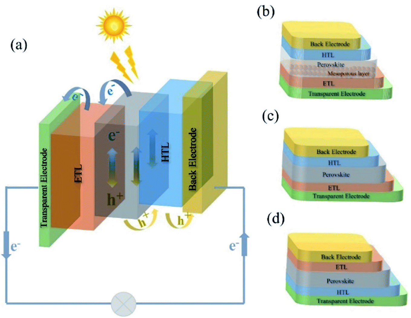 | ||
| Fig. 1 (a) General working principle of PSCs; device architectures of various PSCs: (b) mesoporous n–i–p, (c) planar n–i–p and (d) inverted p–i–n structured PSCs. | ||
2.1 PSC device architectures
The device architectures for PSCs have undergone tremendous advancement within the last decade.36 The architecture of PSCs is mainly classified into direct (n–i–p) and inverted (p–i–n) with either a planar or a mesoscopic structure, where n, i, and p stand for donor-type, intrinsic, and acceptor type semiconductors, respectively (Fig. 1b–d). In a planar regular (n–i–p) architecture, the ETL is deposited on transparent conducting glass (transparent electrode), which is followed by depositing the perovskite active layer, and then the HTL is deposited on top of the perovskite film and topped by a metal contact.23,30 For the mesoporous structure, it refers to the use of a thin and compact titanium oxide (c-TiO2) layer as a hole blocking layer and a mesoporous TiO2 or Al2O3 (m-TiO2 or m-Al2O3) layer as an electron-extraction scaffold to fill with perovskite materials.37 In the inverted (p–i–n) configuration, the HTL is a bottom contact below the perovskite layer while the ETL is on the top and contacts with the back electrode (e.g., Al). In general, high-temperature sintering (450 °C) is required for the normal n–i–p and mesoporous structure that commonly employs TiO2 as an ETL,38 while the p–i–n structure is more compatible with flexible devices because of its low processing temperatures.39,402.2 Key components in PSCs
The overall performance of PSCs depends on several factors: the light harvesting separation efficiency of the light absorber layer, charge separation at perovskite/HTL(ETL) interfaces and charge transport in the perovskite, HTL and ETL, respectively.2.2.3.1 Electron transport layer (ETL). The popular inorganic ETL materials include metal oxides such as TiO2, SnO2 and ZnO.48 For such materials, high temperature sintering is typically required to generate an electrically conducting phase (i.e., anatase for TiO2). Besides, organic ETL materials such as fullerene (C60) and its derivatives (i.e. [6,6]-phenyl-C61-butyric acid methyl ester (PCBM)) have been used in inverted PSCs.49
2.2.3.2 Hole transport layer (HTL). The commonly used organic HTL materials include spiro-OMeTAD [2,2′,7,7′-tetrakis-(N,N-di-p-methoxyphenylamine)-9,9′-spirobifluorene], P3HT [poly(3-hexylthiophene)], PTAA [poly(triarlyamine)], PANI [polyaniline], PTh [polythiophene], PEDOT [poly(3,4-ethylenedioxythiophene)], PEDOT:PSS [poly(3,4-ethylenedioxythiophene):poly(styrene sulfonate)], etc. Taking PEDOT:PSS as an example, it is a polyelectrolyte with hydrophobic PEDOT and hydrophilic PSS and is widely used for inverted PSCs due to its advantages of great transparency in the visible range, high conductivity, and low processing temperature.50 However, the hygroscopic and acidic nature of PEDOT:PSS may cause the degradation and decomposition of the active layer and ITO electrode, and thus reduce the device stability.51–53
Besides, inorganic HTL materials in PSCs include carbonaceous materials (e.g. graphene oxide (GO) and reduced graphene oxide (rGO)) due to their good electrical properties, large specific surface area, and outstanding chemical and physical stability.54–56 However, they also suffer from high oxygen content and poor solvent dispersion, which prevent their wide application.54,57
3. Synthesis of carbon–polymer nanocomposites
Carbon nanomaterials feature the advantages of excellent electrical properties and high stability;18,58–61 however, the growth of nanostructured carbon sheets in a large area with high quality and their incorporation into PSC devices are difficult and expensive for practical applications. On the other side, polymers are relatively cheap and easy to process, but suffer from high resistance and poor mechanical properties.62–64 Therefore, the preparation of carbon–polymer nanocomposites is a promising route to achieve synergistic properties, leading to the improvement in the photovoltaic performance of assembled PSCs.653.1 Carbon materials
Graphene with a 2D layer structure, first synthesized by Andre Geim and Konstantin Novoselov in 2004,66 is considered as the building block for all carbon structure with other dimensionalities. It possesses good optical transparency (≈97.7%),67 a high Young's modulus (≈1 TPa),68 remarkable carrier mobility at room temperature (≈200![[thin space (1/6-em)]](https://www.rsc.org/images/entities/char_2009.gif) 000 cm2 V−1 s−1),69 excellent thermal conductivity (≈5 × 10³ W m−1 K−1),70 and superior environmental stability.71 Regarding its application in PSCs, one main challenge is to obtain uniform and thin graphene films.72 Graphene oxide (GO), the most popular graphene derivative, is a single layer of graphene nanosheets functionalized with epoxy, carbonyl and hydroxyl groups.54,73 These functional groups enable GO to disperse easily in water, but also result in its poor electronic conductivity. Reduced graphene oxide (rGO) that hold fewer functional groups than GO have exhibited improvement in electronic characteristics.74,75
000 cm2 V−1 s−1),69 excellent thermal conductivity (≈5 × 10³ W m−1 K−1),70 and superior environmental stability.71 Regarding its application in PSCs, one main challenge is to obtain uniform and thin graphene films.72 Graphene oxide (GO), the most popular graphene derivative, is a single layer of graphene nanosheets functionalized with epoxy, carbonyl and hydroxyl groups.54,73 These functional groups enable GO to disperse easily in water, but also result in its poor electronic conductivity. Reduced graphene oxide (rGO) that hold fewer functional groups than GO have exhibited improvement in electronic characteristics.74,75
Carbon nanotubes (CNTs), 1D cylindrical carbon allotropes of graphene, discovered by Sumio Iijima,76 include single walled nanotubes (SWNTs) from a rolled single graphene sheet, and multi-walled nanotubes (MWNTs) from the stacking of concentric layers of several graphene layers.77
Carbon dots are considered as a kind of zero dimensional (0D) carbon dominated nanomaterial with sizes less than 10 nm.78 Since the first report of carbon dots in 2004, their superior properties such as tunable photoluminescence, low toxicity and light stability have favored their wide application.79 The abundant functional groups of carbon dots endow them with prospects for modification application in perovskite solar cells and perovskite LEDs.80–82 Carbon dots include graphene quantum dots (GQDs), carbon quantum dots (CQDs), carbon nanodots (CNDs), carbonized polymer dots,78,83etc.
3.2 Preparation methods of carbon–polymer nanocomposites
So far, most polymer–carbon nanocomposites have been prepared through methods of (1) solution blending, (2) in situ polymerization, (3) melt mixing, and (4) coating. Other approaches include electrospinning, electro-deposition, etc. For each method, the detailed preparation process and examples are described as below, and their features are summarized and compared in Table 1.| Methods | Advantages | Challenges |
|---|---|---|
| Solution blending | Simple and commonly used | Requires a large volume of organic solvents and may cause high cost |
| Feasible for large scale production | Residual solvents may influence the properties of the composite | |
| In situ polarization | Deals with insoluble and unstable polymers | Difficult to control the level of polymerization |
| Strong interaction between carbon materials and polymer | ||
| Melt processing | Environmentally friendly | Hard to form a uniform dispersion |
| Thermoplastic polymers | Polymer degradation due to high temperature | |
| Coating | Simple and practical | Layer-by-layer may not homogeneous |
| Various choices for coating techniques |
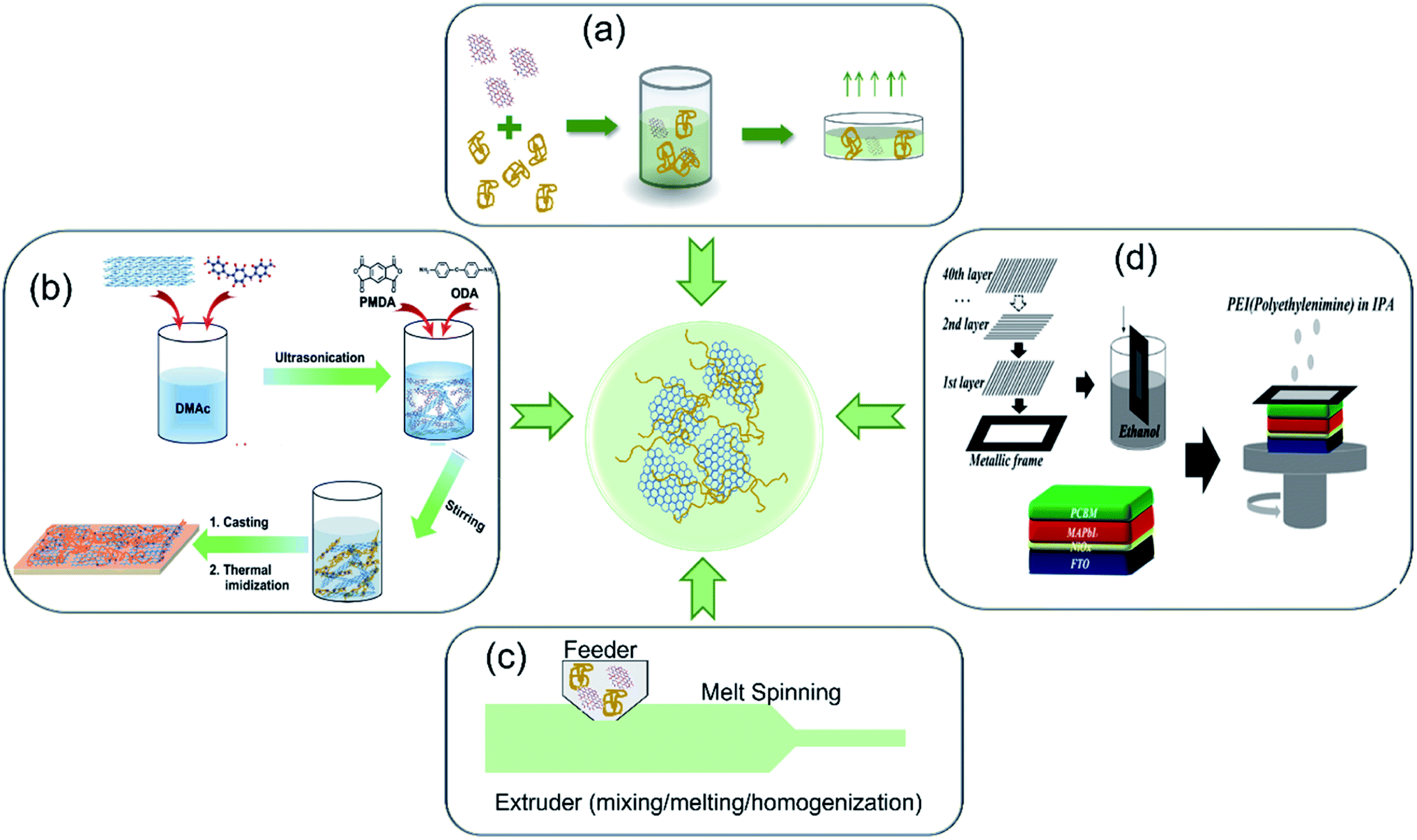 | ||
| Fig. 2 Preparation methods of carbon nanomaterials–polymer composites: (a) solution blending. (b) In situ polymerization. Reproduced with permission.101 Copyright 2017, Royal Society of Chemistry. (c) Melt processing. Reproduced with permission.102 Copyright 2020, Elsevier. (d) Coating. Reproduced with permission.98 Copyright 2018, American Chemical Society. | ||
In addition to the solvent selection, other facile approaches to facilitate the formation of homogeneous mixture solution include: (1) the modification of carbon nanostructures and (2) the functionalization of polymers. In the first way, it involves grafting polymer chains on the surface of carbon nanomaterials to establish strong chemical bonds between them.87 For instance, Gatti et al. attached PhOMe [p-methoxyphenyl] substituents to SWCNT and rGO, respectively,88 to help their good dispersion in P3HT matrix (3 wt% SWCNT∼PhOMe in P3HT and 4 wt% rGO∼PhOMe in P3HT composites). The homogeneous composites promoted the formation of efficient charge percolation pathways in HTL layer. In the second way, functionalizing polymers helps to form a homogeneous mixing and facilitate a good interaction. Jung et al. employed PSSA [poly(styrenesulfonic acid)] as a polymer template for solubilizing and stabilizing PANI in water,89 and then mixed PSSA–PANI aqueous solution with GO dispersion to prepare a graphene–PANI nanocomposite suspension, which was observed to be stable for several weeks without precipitation.
Solution blending is one of the most effective and simple methods to prepare homogeneous composites and also easy to scale-up. Since it uses organic solvents to disperse carbon materials and polymers, the solution blending method requires a drying process to remove solvents. Organic solvents may increase the cost of this method and also possibly affect the composite performance if they are not removed completely.90
There are two approaches to initiate the polymer formation process: a chemical way or physical method. For example, in the chemical polymerization of PANI, an oxidative agent also as the curing agent is required. Ammonium persulfate [(NH4)2S2O8, APS] in HCl solution was dropwise added to the mixture of rGO and aniline [C6H5NH2] in DI water, producing a rGO–PANI composite;91 potassium persulfate [K2S2O8, KPS] also caused the polymerization of anilines along the basal planes of rGO to form rGO–PANI nanocomposites.92 In addition, a physical method (such as plasma treatment) can also initiate the polymer formation. Cogal et al. reported the use of RF-plasma to prepare a PEDOT/PTh–graphene composite, in which graphene powder was spread into the plasma chamber and exposed to plasma produced by the RF generator; meanwhile the monomer vapors flowed through the chamber, leading to polymer formation on the surface of graphene nanosheets.93 In this method, the polymer coating's thickness can be controlled by tuning the deposition time of RF-plasma.
In situ polymerization is a great choice to deal with insoluble and unstable polymers. This technique also leads to a strong interaction between carbon materials and polymers. However, it is challenging to use this method to fully control the polymerization level and achieve high levels of exfoliation in large-scale production.
Compared to the two previous methods, melt processing is less versatile and more environmentally friendly to form carbon–polymer nanocomposites, and thus is favorable for commercial production. But this method usually deals with thermoplastic polymers. And the uniform dispersion of carbon materials is hindered due to the high viscosity of thermoplastic polymers. Additionally, high temperature processing may also cause polymer degradation.
The coating methods such as spin-coating, spray-coating, roll-to-roll, and other coating techniques (lab- or large-scale) are feasible and practical to prepare carbon–polymer composite films. Although these methods often require subsequent drying/sintering and pressing treatment, they are appropriate to produce thin films and coatings.
3.3 Physical and chemical properties of polymer–carbon nanocomposites
The nanocomposites that contain both carbon materials and polymers display impressive physical and chemical properties, including conductivity and thermal and mechanical properties.103Besides the electrical conductivity, the hole mobility of composite interlayers in PSCs was also improved. For instance, a GO doped PEDOT:PSS HTL film showed a hole mobility of 1.57 × 10⁻⁴ cm2 V−1 s−1, about one order of magnitude higher than the value of pristine PEDOT:PSS (5.55 × 10⁻⁵ cm2 V−1 s−1).51
A difference between the inside temperature and ambient temperature of a solar cell module can be as large as 45 °C when it is exposed to sunlight at 100 mW cm−2 irradiance.113 Materials with good thermal conductivity and thermal stability are desired for solar cells. Giuri et al. used DSC and TGA to analyze the thermal behavior of a PEDOT:PSS–GO composite and found that the thermal stability of polymer materials was enhanced when GO was added.86 Besides, the carbon–polymer composite also showed good thermal conductivity. Due to fast heat dissipation through the thermally conductive rGO–PMMA composite, the thermal stability of the PSC device with such a composite film as the encapsulation layer was found to improve.84 The PCE of the device with rGO–PMMA coating was about 80% of initial value after 100 h at 85 °C. Meanwhile the efficiency of bare PSC and PMMA coated PSCs decreased by 50% and 60% in 96 h at 85 °C. The thermally conductive rGO–PMMA coating minimized the thermal damage of PSC devices.
4. Applications of carbon–polymer nanocomposites in PSCs
Carbon nanomaterials such as graphene and carbon nanotubes are incorporated with polymers to form carbon–polymer nanocomposites. These materials have played different roles in PSCs, including as additives in the perovskite layer, electrodes, electron transporters, hole transporters, barrier layers, etc. The PSCs that contain carbon–polymer materials show enhanced performance including higher PCE values and long-term stability. In PSCs, the use of carbon–polymer materials contributes to one or more of the following aspects: (1) high quality perovskite films with high crystallinity and fewer defects; (2) improving conductivity to facilitate charge extraction and transportation; (3) adjustment of the work function between different layers to achieve higher open circuit voltage; (4) great interface contact between layers to enable rapid carrier transport; (5) changing the hydrophobicity and thermal properties to prevent the attack from moisture and heat.4.1 Additives in the perovskite active layer
In the perovskite layer, carbon–polymer nanocomposites can play the following roles: (1) protective coating on the surface of perovskite and (2) an additive in the perovskite layer.First, a protective coating on the perovskite surface is to prevent its degradation in working environments (air and humid). Rajamanickam et al. reported the deposition of a graphene–PANI composite on the top of a CH3NH3PbI3 layer to protect it from degradation.117 The morphology image (Fig. 3a and b) showed that the perovskite crystals were fully encapsulated by the graphene–PANI composite rather than exposed to ambient conditions in the cases of graphene nanosheets- and PANI-only. The assembled PSCs were exposed for 96 h to extremely high humidity (99% RH), and no perovskite degradation was observed. Moreover, a thick graphene–PANI composite coating (∼4 μm) increased the tortuosity for water molecules and oxygen diffusion into the perovskite material. In addition, Ahn et al. designed a carbon-sandwiched PSC structure (Fig. 3c, C60/MAPbI3/SWCNT), in which a lead halide perovskite layer was sandwiched by C60 and SWCNTs without metal electrodes.118 The PSC devices with three HTMs (spiro-MeOTAD, PTAA and P3HT) incorporated in SWCNTs gave an average PCE of 17.0%, 15.3% and 13.6%, respectively. The supramolecular CNT–polymer hybrids were formed by inducing π–π interactions between polymers and CNTs;119 specifically, P3HT led to a much better stability than PTAA due to its planar conformation, which led to a close interaction with CNTs by wrapping around nanotubes.
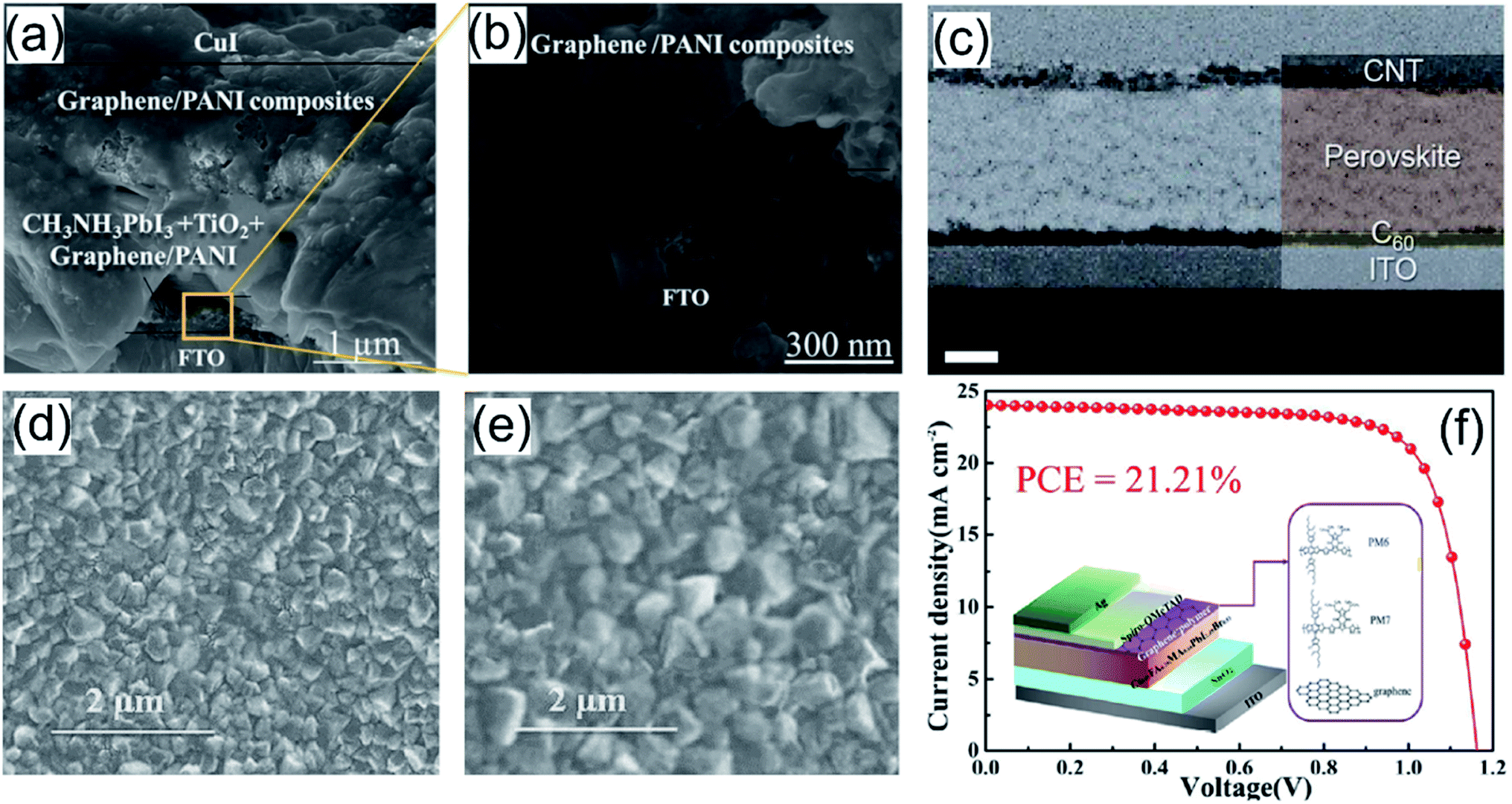 | ||
| Fig. 3 (a) and (b) Cross-sectional scanning electron microscopy image of the graphene/PANI protected CH3NH3PbI3 solar cell. Reproduced with permission.117 Copyright 2016, Institute of Physics Publishing. (c) Cross-sectional SEM images of the ITO/C60/MAPbI3/CNT device with a carbon-sandwich structure. Reproduced with permission.118 Copyright 2018, Royal Society of Chemistry. (d) FSEM images of CH3NH3PbI3 and (e) FSEM images of perovskite + rGO–P3HT. Reproduced with permission.120 Copyright 2019, Elsevier. (f) Device architecture and J–V curve for the best devices of PSCs based on graphene/PM6. Reproduced with permission.123 Copyright 2021, American Chemical Society. | ||
Second, additives are used to influence the crystallization and growth of perovskites or reduce defects in perovskite materials during operation. Sarvari et al. grafted reduced graphene oxide with P3HT (or PTEt) and added the rGO–P3HT composite (or rGO–PTEt) into the perovskite precursor solution.120 The composite additives effectively enhanced the grain size and increased the crystallinity (Fig. 3d and e), and thus improved the absorbance efficiency of pristine perovskite due to grafting of the rGO surface with the polymeric backbones. The P3HT–rGO-based PSC device showed a PCE of 15.15% with a Voc of 0.95 V, a Jsc of 22.15 mA cm−2, and an FF of 72%. In addition, for working PSC devices, some harmful defects (i.e. local positive and negative ion vacancies) are formed as the cation and halogen ions of perovskite migrate under the internal electric field of the device.121,122 Recently, Lou et al. added a graphene–polymer (e.g. PM6, PM7 Lewis base conductive polymer) nanocomposite during the antisolvent step of Cs/FA/MA [Cs0.05FA0.79MA0.16PbI2.49Br0.51].123 The highly conductive graphene–polymer composites not only passivated the defects dominated by state traps, but also facilitated the charge transport in the perovskite film, which reduced the interfacial charge density and trap-assisted charge recombination. The PSCs with a graphene–PM6 composite additive showed a high PCE of 21.21% (Fig. 3f) with a Voc of 1.17 V, a Jsc of 24.03 mA cm−2, and an FF of 76%, compared to the PCE (18.21%) of the control device without the composite. Moreover, due to the hydrophobicity of polymer–graphene composites, the graphene–PM6 and graphene–PM7-based devices showed outstanding stability by maintaining 90% and 85% of the initial PCE after 480 h aging under ∼35% RH at room temperature, respectively.
4.2 Electrode
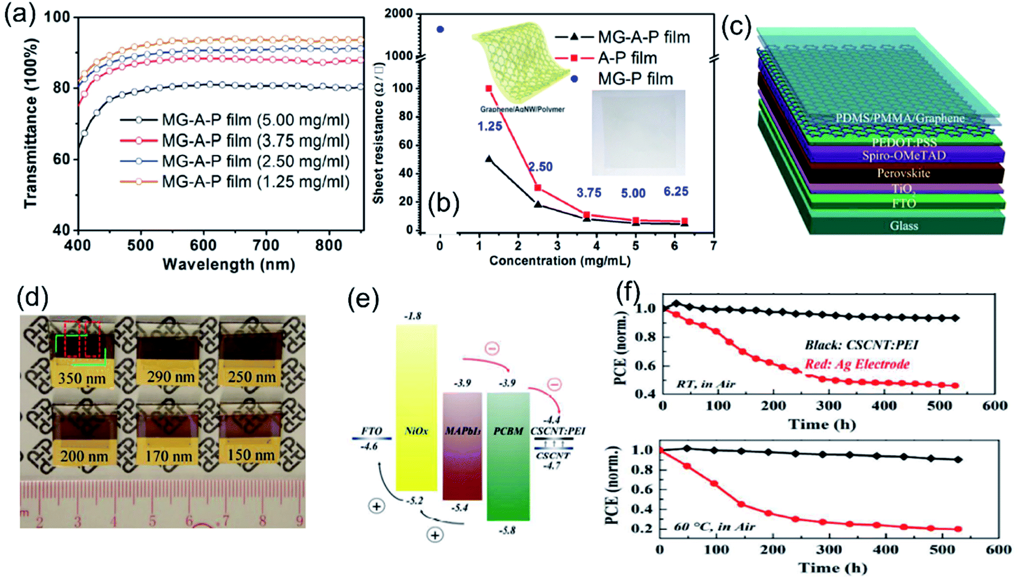 | ||
| Fig. 4 (a) Optical transmittance spectra of the graphene–AgNWs–polymer (MG–A–P) film with various concentrations of AgNWs and (b) sheet resistance of the MG–P, MG–A–P, and A–P hybrid films with different concentrations of AgNWs. Reproduced with permission.100 Copyright 2016, American Chemical Society. (c) Schematic diagram of a semitransparent perovskite solar cell using graphene as the counter electrode and (d) photos of semitransparent perovskite solar cells with transparent graphene electrodes. The thicknesses of the perovskite layers in the six devices are approximately 350, 290, 200, 170, and 150 nm, respectively. Reproduced with permission.58 Copyright 2015, Wiley-VCH. (e) Schematic energy level diagram of the FTO/NiOx/MAPbI3/PCBM/CSCNT:PEI device and (f) the variation of the PCE of Ag and CSCNT:PEI based PSCs as a function of ageing time at room temperature (RH: 10–50% and T: 20–30 °C) and with a constant temperature of 60 °C. Reproduced with permission.98 Copyright 2018, American Chemical Society. | ||
Carbon–polymer composites, as back electrode candidates, show the advantages of (1) easy to process to thin films with tunable thickness and components as well as properties; (2) low cost and excellent mechanical properties; (3) great stability towards perovskite structures. However, the conductivity of the composites is relatively lower than that of metal electrodes especially when insulating polymers are added. Thus, the combination of metal and transparent conductive oxide electrodes leads to high efficiency of PSC devices.
4.3 Encapsulation layer
CNMs–polymer composite coatings also function as a barrier layer, which significantly increases the long-term stability of PSCs in humid and hot environments. Han et al. deposited a PMMA–rGO composite (PRC) passivation layer on the top surface of PSCs (Fig. 5a).84 The rGO nanosheets with hydroxyl groups and amphiphilic PMMA molecules with carbonyl groups contributed to the hydrophobic nature (Fig. 5b) and better thermal conductivity of the PMMA–rGO composite coating, improving the photovoltaic stability under humid environment and high-temperature conditions. With the PMMA–rGO passivation layer, the PSC devices displayed a slight decrease of 10% of the PCE after exposure to very humid conditions (RH > 75%) for 500 hours. When exposed to 90 °C for 100 hours, the PCE of PSC devices with the passivation layer was maintained at 12.6%, which is about 80% of the initial value (Fig. 5c). Jang et al. reported an encapsulation layer consisting of GO and SiO2 fillers in the EVOH [poly(vinyl alcohol-co-ethylene)] matrix (Fig. 5d).127 SiO2 nanoparticles (5 wt%) were added into EVOH to reduce the permeation of oxygen and water and introducing 1 wt% GO into EVOH/SiO2 further decreased the water vapor transmission rate (WVTR). The EVOH–GO–SiO2 encapsulation layer did not damage the efficiency of PSC devices, which showed a PCE of 17.86% with and 17.28% without the layer (Fig. 5e). Moreover, with the composite protective layer, the PSC devices retained approximately 86% and 61% of the initial PCEs after 5 and 10 h from the onset of the reservoir test (direct contact with water on the encapsulated surface). In comparison, the unencapsulated device was immediately degraded after contacting with water (Fig. 5f). Table 2 summaries the device configurations and PV performances of PSCs using carbon–polymer composites as additives, electrodes and encapsulation layers.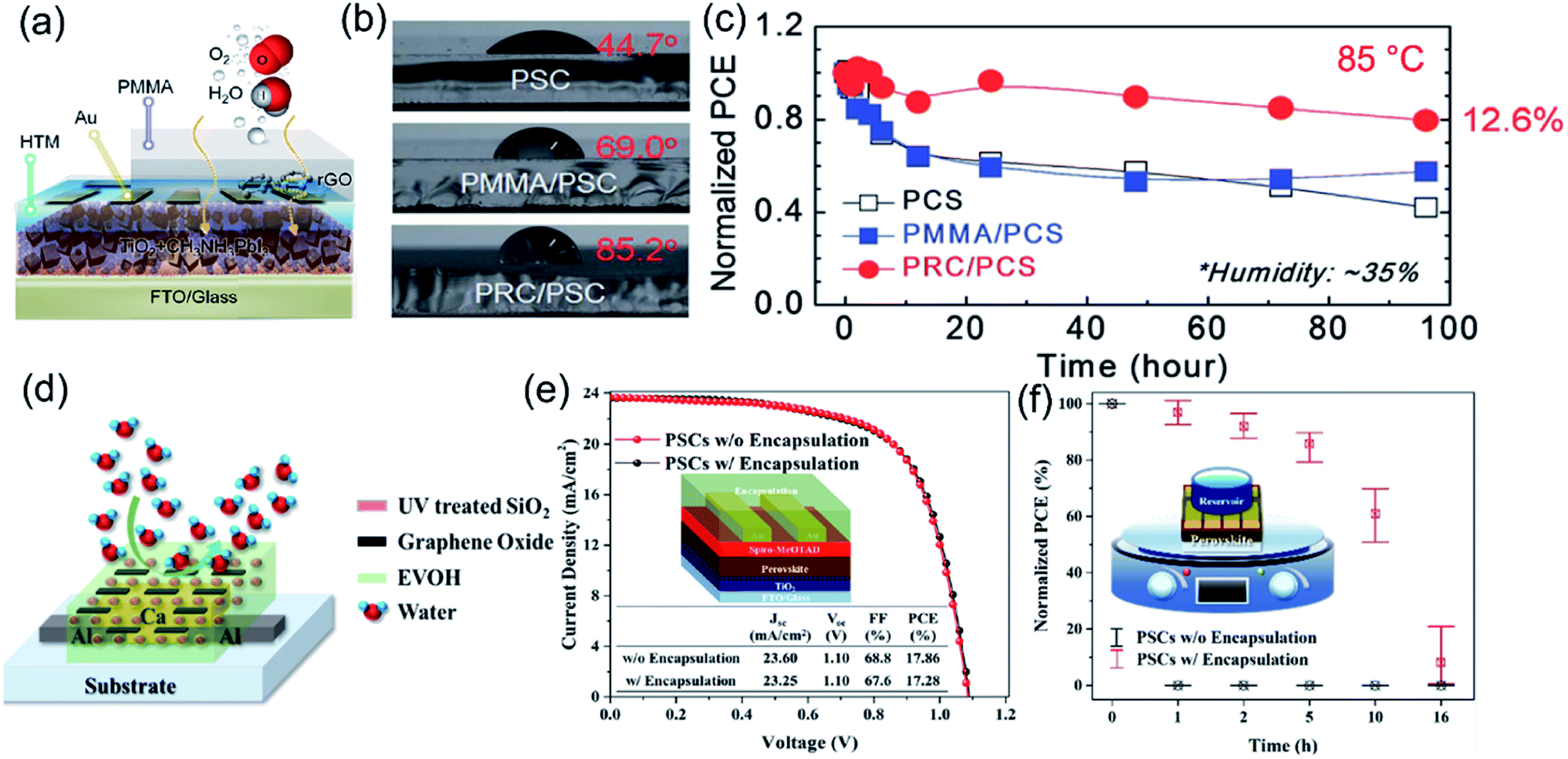 | ||
| Fig. 5 (a) Schematic representation of the hydrophobic surface and external matter following a complex path through the PRC layer, (b) water contact angles of bare cells, PMMA/PSC and PRC/PSC on the top, and (c) change in the PCE of PSCs at 85 °C for 96 h (normalized using the PCEs of the as-fabricated cells). Reproduced with permission.84 Copyright 2017, Royal Society of Chemistry. (d) Scheme of PSCs encapsulated with EVOH/S5/UV/G1, (e) efficiency of PSCs before and after encapsulation, and (f) reservoir test of PSCs encapsulated with EVOH/S5/UV/G1. Reproduced with permission.127 Copyright 2019, American Chemical Society. | ||
| Role | Composite materials | Perovskite | Electrode/ETL | HTL/electrode | PCE (%) | J sc (mA) | V oc (V) | FF (%) | Stability | Ref. |
|---|---|---|---|---|---|---|---|---|---|---|
| Additive in the perovskite layer | Graphene–PANI | CH3NH3PbI3 | FTO/TiO2 | CuI/Au | — | — | — | — | <10% decrease, 96 h, 99% RH | 117 |
| rGO–P3HT | CH3NH3PbI3 | FTO/b-TiO2/mp-TiO2 | Spiro-OMeTAD/MoO3/Ag | 15.1 | 22 | 0.95 | 72 | N/A | 120 | |
| Graphene–PM7 | Cs0.05FA0.79MA0.16PbI2.49Br0.5 | ITO/SnO2 | Spiro-OMeTAD/Ag | 21.2 | 24 | 1.16 | 76 | 10% decrease, 480 h, 35% RH | 123 | |
| CNT–PTAA | CH3NH3PbI3 | ITO/C60 | CNT–PTAA | 15.3 | 23 | 0.98 | 67 | N/A | 118 | |
| Electrode | Graphene–PEDOT:PSS | CH3NH3PbI3xClx | FTO/TiO2 | Spiro-OMeTAD/PEDOT:PSS–graphene | 12.3 | 19 | 0.96 | 67 | N/A | 58 |
| MG–A–P | CH3NH3PbI3 | Ag/BCP/PCBM | MoO3/MG–A–P | 10.4 | — | — | — | N/A | 100 | |
| CSCNT–PEI | MAPbI3 | CSCNT–PEI/PCBM | NiOx/FTO | 10.8 | 18 | 0.95 | 61 | 94% remained after 500 h | 98 | |
| CNT–P3HT | CH3NH3PbI3 | FTO/c-TiO2/m-TiO2 | CNT–P3HT | 13.4 | 22 | 0.91 | 65 | 97% remained after 40 days | 85 | |
| Encapsulation layer | rGO–PMMA | CH3NH3PbI3 | FTO/mp-TiO2 | Spiro-OMeTAD/Au | 15.7 | 22 | 1.01 | 0.68 | 100% remained after 1000 h in air | 84 |
| EVOH–GO–SiO2 | CH3NH3PbI3 | FTO/TiO2 | Spiro-OMeTAD/Au | 17.3 | 23 | 1.1 | 67 | 86% remained after 5 h in contact with water | 127 |
4.4 Charge transport layer
Carbon nanomaterials–polymer composites are proven to be good candidates for both ETL and HTL materials in PSC structures. In the composite, the combination of polymer (amorphous nature and strong intrachain charge transfer along the conjugated backbone) and carbon nanomaterials with great conductivity enables their good balance between high film quality and charge mobility.In 2016, Tong et al. demonstrated the use of mesoporous graphene–PANI (mp-GP) as a ETL candidate in PSC devices (Fig. 6a) with good thermal stability.92 The network structure of the mp-GP composite contains pores (100–400 nm), which not only form well-connected fast electronic channels but also allow for the formation of larger perovskite crystals (Fig. 6b and c). The resultant mp-GP based PSC device displayed a remarkable PCE of 13.8% in comparison to 9.3% of the rGO based device. Regarding the stability, it is known that the basicity of ETL materials (e.g. ZnO) is one driving force for the thermal decomposition of perovskite.130 Mp-GP with a low isoelectric point strengthened the stability of perovskite better against thermal decomposition. Moreover, the mesoporous architecture protected the inner perovskite grains from moisture attack and reactive interface formation. For mp-GP based devices, their PCE remained at ∼88% of initial efficiency after 200 h thermal annealing at 150 °C. This mesoporous graphene–polymer composite served as a promising ETL material.
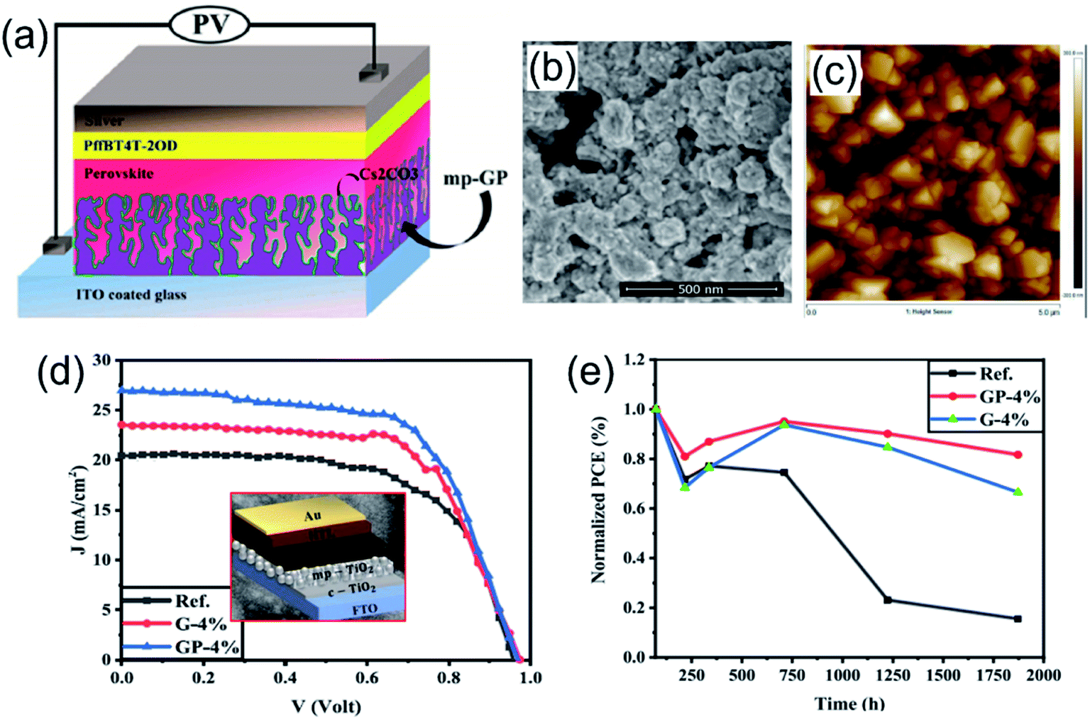 | ||
| Fig. 6 (a) Schematic view of the device structure with ITO/mp-GP or rGO/Cs2CO3/CH3NH3PbI3/PffBT4T-2OD/Ag, and (b) SEM image and (c) AFM image of the topography of the mp-GP thin films. Reproduced with permission.92 Copyright 2016, American Chemical Society. (d) The J–V of the perovskite solar cells (PSCs) fabricated based on pure mp-TiO2 and the mp-TiO2 ETL modified with the rGO–PANI nanocomposite or pure rGO, and (e) stability test of different perovskite solar cells inside a dry airbox with a relative humidity of about 20% in the dark at room temperature. Reproduced with permission.91 Copyright 2021, Elsevier. | ||
Recently, Mohseni et al. added a rGO–PANI nanocomposite as an additive to a typical mesoporous TiO2 (mp-TiO2) ETL precursor in mesoscopic-type PSCs, leading to the reduction in surface defects and passivated grain boundaries of the upper perovskite layer.91 Furthermore, the incorporation of the rGO–PANI nanocomposite strengthened the charge transfer in the ETL layer as well as the interface with the perovskite. The 4 vol% rGO–PANI-based device achieved the highest PCE of 16.48% (Fig. 6d) and also displayed enhanced stability, whereas 82% of initial PCE was maintained over an aging time of 1870 h inside a dry airbox at a temperature of 20–30 °C (Fig. 6e). In contrast, the PCE of the rGO-based device declined to 15% of its original value.
To take advantage of the high conductivity and hydrophobicity of pristine graphene, nanocomposites of graphene–polymers have been explored using various polymers such as PEDOT, PEDOT:PSS, and P3HT. In 2018, Cogal et al. reported the preparation of nanocomposites of graphene with PTh [polythiophene] or PEDOT prepared using radio frequency (RF) plasma polymerization.93 They found that the PSC devices with I2 doped PEDOT–graphene showed higher PCE (8.79%) than I2 doped PTh–graphene (4.95%). Later, Redondo-Obispo et al. reported the incorporation of few-layer graphene platelets into PEDOT:PSS (Fig. 7a) to form a HTL composite, which influenced the subsequent growth of the perovskite layer (i.e. inhibited the formation of PbI2 and decreased grain boundary density).132 The G-doped PEDOT:PSS composite also exhibited better charge extraction and reduction of recombination at the interface between the composite HTL and perovskite. The PSC device with a 0.02 mg mL−1 G-doped PEDOT:PSS HTL displayed the highest PCE (Fig. 7b). In 2019, Chu et al. developed a P3HT–graphene composite to replace pure P3HT as the HTL material in PSC devices (Fig. 7c).133 The graphene–P3HT composite exhibited an outstanding hole mobility of 1.2 × 10⁻² cm2 V−1 s−1, two orders of magnitude larger than that of pure P3HT. The carbon-based PSC with the graphene–P3HT composite achieved a high PCE of 18.1% in comparison to 11.1% of the pure P3HT-based PSC. Impressively, the devices with the graphene–P3HT composite HTL showed long-term stability, which was revealed by 97% remained PCE after storage for 1680 hours under ambient conditions (RH 50%) without illumination (Fig. 7d). In addition to pristine graphene, a functional graphene (F-graphene)-modified P3HT composite has been prepared by Ye et al. and employed as a HTL in PSC devices. The high conductivity of F-graphene enhanced the hole mobility of the composite HTL and modified the energy level of the device (Fig. 7e).134 Using 4 wt% F-graphene in the P3HT layer, the PSCs with the composite HTL showed the highest EQE value and IPCE value (Fig. 7f), consistent with the highest PCE of 13.82%.
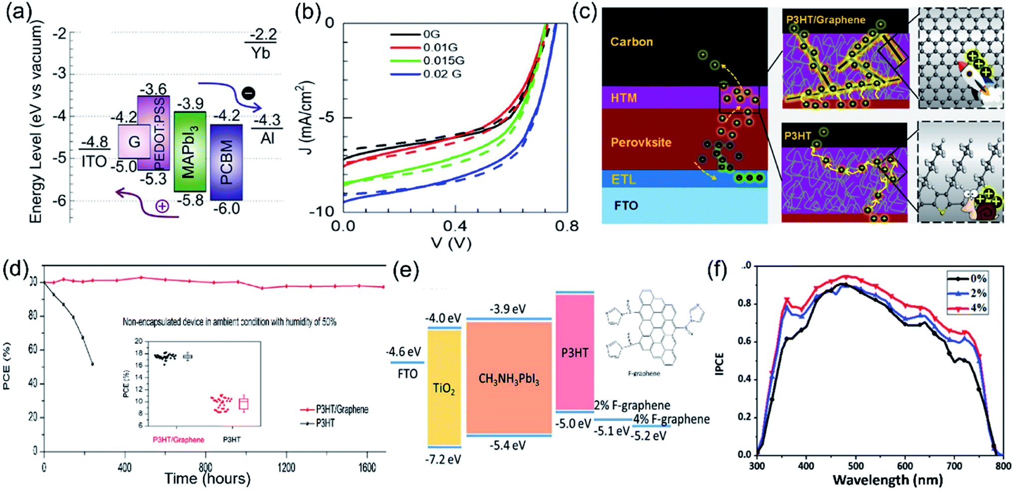 | ||
| Fig. 7 (a) Energy level diagram for a PSC with graphene-doped PEDOT:PSS as the HTL material, (b) current–voltage performances under 1 sun illumination for the solar cells based on 0G, 0.005G, 0.01G, 0.015G and 0.02G as HTLs in forward sweep (solid lines) and reverse sweep (dashed lines). Reproduced with permission.132 Copyright 2020, Elsevier. (c) Illustration of a device with P3HT as the HTL, where the hole transport is slow, resulting in charge accumulation, and a device with the P3HT–graphene composite HTL, where holes are transported to the carbon electrode quickly, and (d) normalized PCE evolution of non-encapsulated devices with P3HT and graphene–P3HT as the HTLs stored in the dark for 1680 h in air; the inset shows the statistical PCEs of devices with graphene–P3HT and P3HT as HTLs. Reproduced with permission.133 Copyright 2019, Elsevier. (e) The schematic energy diagram of the hole-transporting layer involved in the PSCs and (f) the corresponding external quantum efficiency (EQE) spectra of the PSC devices with various HTMs. Reproduced with permission.134 Copyright 2016, Royal Society of Chemistry. | ||
Graphene oxide (GO) has been used to form composites with polymers including PEDOT:PSS, PEDOT, and PANI. In 2016, Lee et al. investigated a GO–PEDOT:PSS composite as the HTL for planar PSCs, and they observed higher photovoltaic performance of PSCs with the composite HTL (9.74%) than those of pristine PEDOT:PSS (8.23%) and GO (6.42%) HTLs.131 The enhanced performance is attributed to more efficient hole transport and collection. In 2018, Yu et al. fabricated inverted PSCs through the solution-mixing method to prepare a GO–PEDOT:PSS composite as the HTL.135 The GO–PEDOT:PSS (volume ratio of 2 to 1) composite showed a better matched HOMO level (5.42 eV) with that of the perovskite layer (5.4 eV) than pristine PEDOT:PSS (5.08 eV) (Fig. 8a), improving the hole extraction. The inverted PSC with the composite HTL displayed a PCE of 18.09%, higher than that of the PSC with pristine PEDOT:PSS (14.95%). The steady-state and time-resolved photoluminescence (PL) spectra (Fig. 8b) also confirmed that the PL intensity of the perovskite film prepared on the PEDOT:GO composite decreased about 97%, along with a remarkably decreased exciton lifetime. With the GO–PEDOT:PSS composite HTL, Niu et al. studied the influence of different concentrations of GO on the photostatic performance of PSC devices.51 The GO doping into PEDOT:PSS reduced the root mean square (RMS) roughness value (Fig. 8c) and provided a high quality surface for perovskite deposition. They observed that the PSC with PEDOT:PSS + 500 μL GO showed the highest Jsc value (20 mA cm−2) and PCE (14.2%) since the oversaturated GO in composites caused segregation and barriers between GO and PEDOT:PSS as well as poor conductivity. In addition, Mabrouk et al. compared five different HTL materials for p–i–n PSCs: pristine GO, PEDOT:PSS, PEDOT:PSS–PANI (2/1), GO–PANI (2/1), and PANI–PEDOT:PSS–GO (1:1:1) (Fig. 8d).107 When using the GO–PEDOT:PSS–PANI (ratio of 1:1:1) composite as the HTL, the PSC device achieved the highest efficiency of 18.12%. The enhanced Jsc value was attributed to the higher conductivity and well-matched energy levels (Fig. 8e); meanwhile, the improved Voc resulted from the increase of the work function after adding GO to PEDOT:PSS–PANI. The surface chemistry of GO can be functionalized with atomic groups and form composites with polymers. Guo et al. prepared sulfated graphene oxide (sGO) with –SO3H groups and combined it with PEDOT:PSS to form composites as HTLs for PSCs.136 They found that sGO as a HTL showed better device efficiencies (max. PCE 9.9%) than the GO HTL (max. PCE 6.7%). Moreover, the 1:1 sGO–PEDOT composite HTL based device achieved the best PCE of 13.9% and less photocurrent hysteresis due to the most efficient charge carrier generation and transfer.
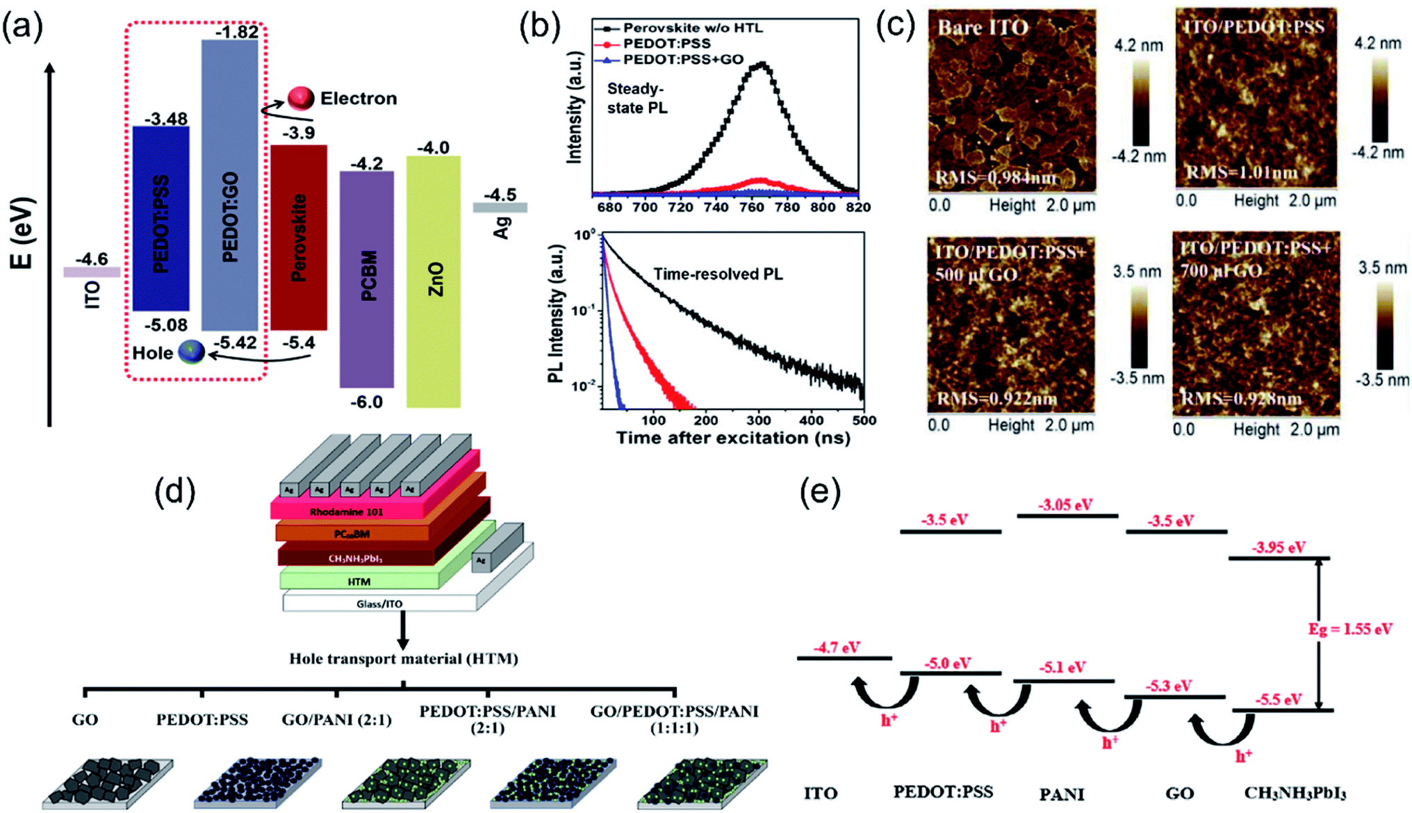 | ||
| Fig. 8 (a) Relative energy levels of the various device components in the perovskite solar cells, (b) steady-state PL spectra and time-resolved PL spectra of perovskite films prepared on PEDOT:PSS and GO–PEDOT:PSS composites, respectively. Reproduced with permission.135 Copyright 2018, Springer Nature. (c) AFM images of GO-doped PEDOT:PSS films spin-coated on ITO glass using different concentrations. Reproduced with permission.51 Copyright 2017, Elsevier. (d) Structure of p–i–n perovskite solar cells using different HTMs:GO, PEDOT:PSS, GO–PANI, PEDOT:PSS–PANI, and GO–PEDOT:PSS–PANI nanocomposites, and (e) schematic diagram showing the energy levels of ITO, CH3NH3PbI3 perovskite and different HTMs, including PEDOT:PSS, PANI, and GO. Reproduced with permission.107 Copyright 2020, Wiley-VCH. | ||
Reduced graphene oxide (rGO) as another 2D graphene derivative has been explored to prepare carbon–polymer composites for HTL materials. Jung et al. prepared rGO–PANI nanocomposite films and demonstrated them as HTL materials in inverted PSCs.89 The rGO–PANI based device achieved a PCE of 16.61%, higher than that of PSCs with GO–PANI as the HTL (14.1%) (Fig. 9a). The enhanced photostatic performance was attributed to the higher conductivity and better energy level matching to the perovskite layer with the rGO–PANI nanocomposite (Fig. 9b). Recently, Cho et al. used an electron beam to reduce a GO–PVP composite in aqueous ethanol solution and prepared a highly dispersible rGO–PVP nanocomposite.137 PVP acted as a stabilizer to impede the re-aggregation during the reduction process of GO. When used as a HTL in PSCs, the aggregation-free rGO–PVP nanocomposite showed the highest PCE of 11.36% (Fig. 9c) and more efficient photon-to-electron conversion than other HTL materials (GO, PVP, and PEDOT:PSS) (Fig. 9d). To obtain better dispersion in polymer, Cho et al. employed high energy 60Co γ-ray irradiation to produce smaller GO sheets (Fig. 9e) and uniform distribution of γ-ray irradiated GO in PEDOT:PSS.138 The better dispersion resulted in more efficient hole charge transport between GO and PEDOT:PSS in the HTL. The γ-ray-GO embedded PEDOT:PSS interlayer assisted in improving the crystallinity of the perovskite layer, resulting in a higher photovoltaic performance with a PCE of 12.76% than the devices without GO or with pristine GO (Fig. 9f). Moreover, the photoluminescence spectra (Fig. 9g) also confirmed the best charge separation in the PSCs with a γ-ray-GO–PEDOT:PSS composite.
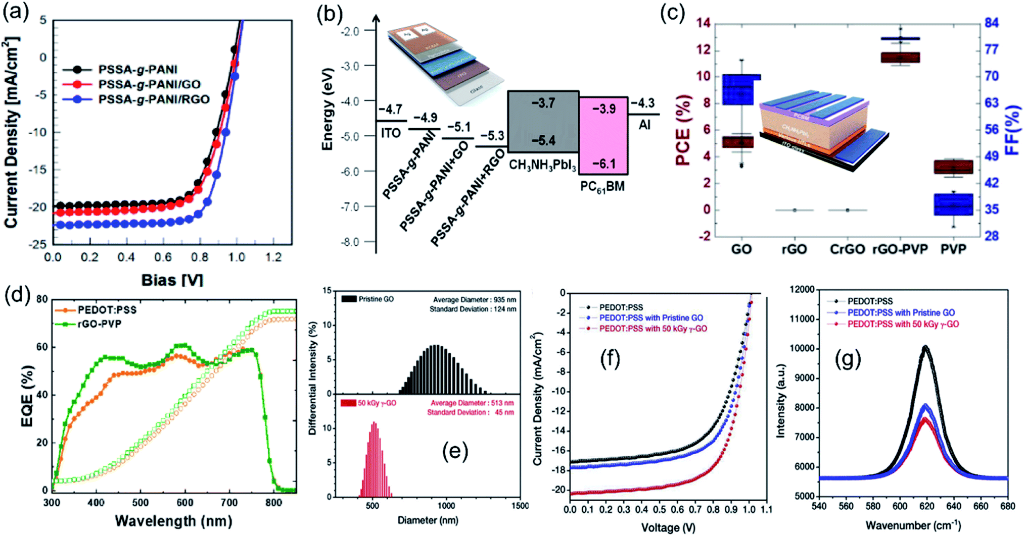 | ||
| Fig. 9 (a) J–V curves of PSCs with PANI, GO–PANI, and rGO–PANI as HTLs under 1-sun illumination and (b) energy levels of composite films in PSCs (inset shows the schematic device structure). Reproduced with permission.89 Copyright 2021, Multidisciplinary Digital Publishing Institute. (c) Statistical data of the PCE and FF of PSCs with various HTLs (inset shows the schematic of the rGO–PVP-based PSC device structure) and (d) EQEs with the integrated Jsc of PSCs using PEDOT:PSS and rGO–PVP as HTLs. Reproduced with permission.137 Copyright 2021, Elsevier. (e) Size distributions of pristine GO and 50 kGy γ-ray-GO dispersed in water measured by DLS measurements, (f) J–V curves and EQE spectra of the cells with PEDOT:PSS, PEDOT:PSS with pristine GO, and PEDOT:PSS with 50 kGy γ-ray-GO as hole transport layers, and (g) photoluminescence spectra of perovskite layers on the PEDOT:PSS layer, PEDOT:PSS with GO, and with 50 kGy γ-ray-GO. Reproduced with permission.138 Copyright 2018, Elsevier. | ||
Carbon dots usually have various functional groups such as carbonyl, hydroxyl, and epoxy groups.82 The interaction between carbon dots and PEDOT:PSS can enhance the conductivity of the composite. Li et al. incorporated graphene quantum dots (GQDs) into PEDOT:PSS and used this composite film as a HTL.139 They found that GQDs increased the conductivity of the composite film because graphene quantum dots interacted with the PEDOT:PSS chain, leading to phase separation. The average PCE was boosted from 12.77% for PEDOT:PSS based PSCs to 15.24% for PEDOT:PSS–GQD based devices. Li et al. developed a S, C co-doped carbon nanodots (CNDs)–PEDOT:PSS composite HTL for inverted PSCs.140 The sulfur double bond of functionalized CNDs banded the superfluous PSS and removed the insulating component from the PEDOT:PSS mixture, resulting in conductivity and hole extraction capability enhancement. Meanwhile, the amidogen on the surface of functionalized CNDs neutralized hydrogen ions from PSS and lowered the level of acidity of PEDOT:PSS. The optimized PSCs demonstrated a promising air stability and photovoltaic performance including a Voc of 1.01 V, a Jsc of 22.6 mA cm−2, and a FF 79.06%, yielding a PCE of 18.03%.
Polymer-functionalized single walled carbon nanotubes (SWNTs) have been employed to work as a HTL material. In 2014, Habisreutinger et al. wrapped P3HT with SWNTs to form a supramolecular nanohybrid film by spin-coating and combined it with insulating PMMA to prepare meso-superstructured PSCs (Fig. 10a).17 The P3HT–SWNT–PMMA based PSCs displayed a maximum PCE of 15.3% and impressive thermal stability, where the average scanned PCE before and after thermal stressing at 80 °C for 96 h changed from 11.1 to 10.1%. In addition, the PSC device on SWNT–P3HT–PC showed improved thermal stability at temperature above 80 °C (Fig. 10b) as well as moisture stability by the comparison of an unsealed device before and after exposure to running water (Fig. 10c). The composite of functionalized SWNTs within the inert polymer matrix achieved competitive efficiency and offered resilience against thermal and moisture stressing. The authors also deposited spiro-OMeTAD on the P3HT–SWNT layer.141 Spiro-OMeTAD filled the opening and gaps of the nanotube layer, which facilitated an efficient charge transfer. The device with a stratified structure of P3HT–SWNT and Spiro-OMeTAD yielded a PCE of 15.4%. In 2017, Habisreutinger et al. further demonstrated a PCE of 18.8% for the device with a double-layer structure of P3HT–SWNT and spiro-OMeTAD as a hole-transporting p-type layer and FA0.83MA0.17Pb(I0.87Br0.17)3 as an absorber.142 Besides, Wang et al. reported the use of a SWNT–GO–PMMA thin film as a hole conductive protecting layer in PSCs.99 In the composite, GO acts as an electron-blocking layer, while SWNT functions as an efficient carrier dissociation and hole extraction layer in the band alignment (Fig. 10d). Combined with the PMMA layer as an effective barrier, high photovoltaic performance stability was achieved for SWNT–GO–PMMA based PSCs, where the PCE changed from 10.5% to 10% after 10 days, compared with that of the spiro-OMeTAD based PSC which dropped from 10.5% to 5.8%. The PSC with SWNT–GO–PMMA as the HTL showed a high PCE of 13.3% (Fig. 10e). When P3HT was in conjunction with MWCNTs and used as a HTL in a CsPbI2Br PSC, Wang et al. demonstrated that a conversion efficiency of 10.01% was achieved due to enhanced hole extraction and transport.143 MWCNTs–P3HT composites also prevented moisture ingress, and ∼85% of initial PCE was retained over 240 h under ambient conditions.
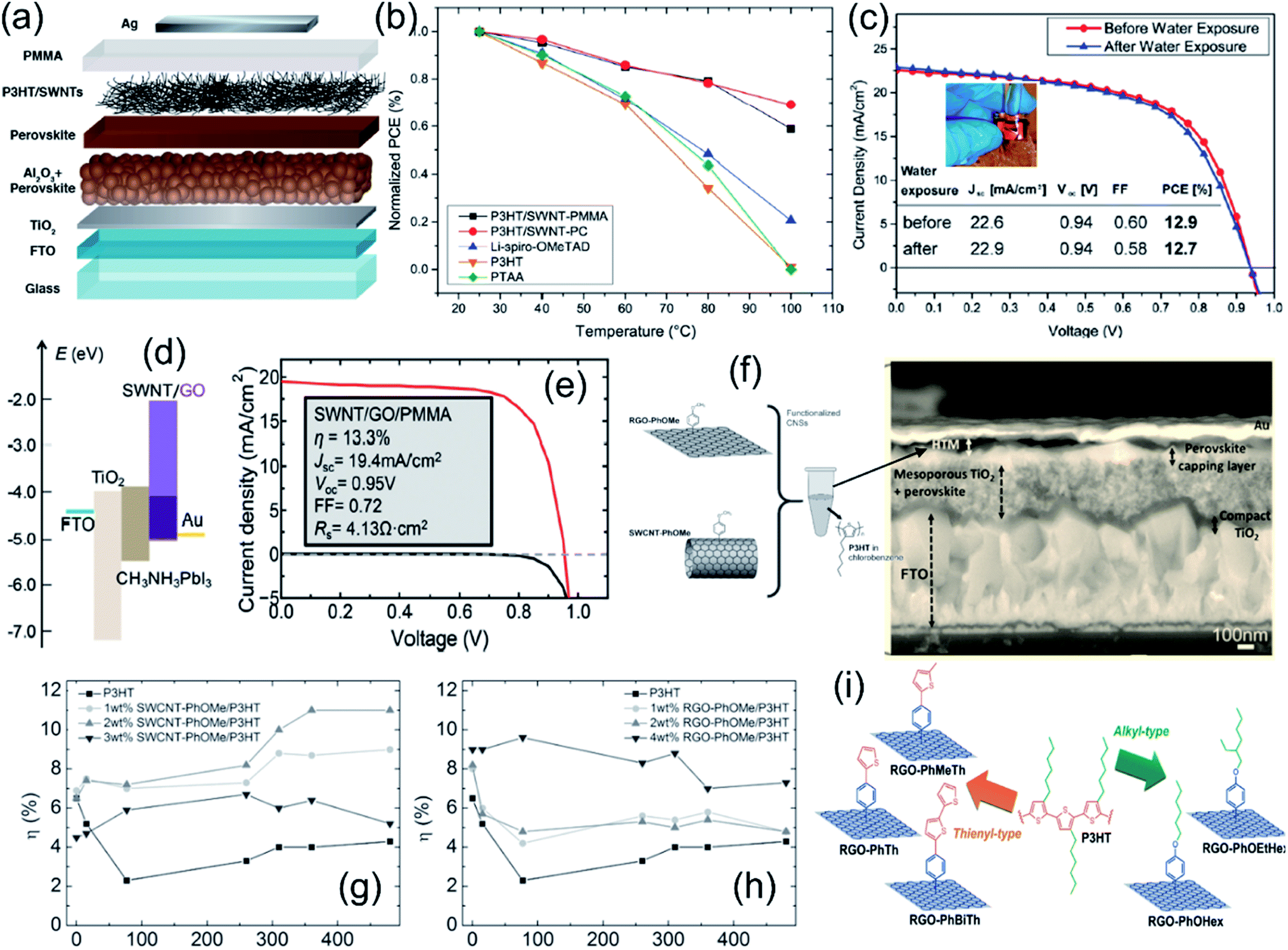 | ||
| Fig. 10 (a) Schematic illustration of the solar cell with a carbon nanotube–polymer composite as the hole-transporting structure, (b) power conversion efficiency of perovskite solar cells employing a range of hole-extraction layers as a function of temperature, and (c) current density–voltage plots recorded under AM1.5 simulated sunlight of 100 mW cm−2 irradiance of a complete perovskite solar cell employing a SWNT–P3HT–PC hole-extraction layer before and after being placed under running water for 60 s; the inset shows a photograph of the same perovskite solar cell placed under a flowing tap with the active layer on top. Reproduced with permission.17 Copyright 2014, American Chemical Society. (d) Band alignment in a perovskite/SWNT/GO solar cell and (e) J–V curve of a perovskite solar cell using SWNT–GO–PMMA as the HTL under light (red solid line) and in the dark (black solid line). Reproduced with permission.99 Copyright 2016, Royal Society of Chemistry. (f) Left: p-methoxyphenyl functionalized carbon nanostructure–P3HT blend and right: cross-sectional SEM images of a perovskite solar cell with a 1 wt% rGO–PhOMe–P3HT blend HTM, (g) endurance tests for devices based on SWCNT–PhOMe–P3HT blends, and (h) endurance tests for devices based on rGO–PhOMe–P3HT blends used as HTMs. Reproduced with permission.88 Copyright 2016, Wiley-VCH. (i) Schematic illustration of the five types of functionalized rGO species reported in ref. Reproduced with permission.144 Copyright 2018, Wiley-VCH. | ||
For composite HTL materials, the prevention of CNM aggregation in the polymer matrix is a key issue to create well-separated pathways for charge percolation in a specific direction at the nanoscale level. Thus, the functionalization of carbon nanomaterials with organic groups is a useful way to facilitate their homogeneous dispersion in polymer matrices. In 2016, Gatti et al. reported a P3HT [poly(3-hexylthiophene)] matrix doped with organic functionalized SWCNTs and rGO as the HTL in PSC devices.88 To facilitate the dispersion of SWCNTs and rGO in the P3HT polymer matrix, p-methoxyphenyl substituents were introduced to form composite HTLs (Fig. 10f). Using 2 wt% SWCNT–PhOMe–P3HT and 4 wt% rGO–PhOMe–P3HT composites, the best PCEs of 11.6% and 10% for planar PSCs were achieved, and PCEs of 11% and 7.3% were retained after a 480 h endurance test, respectively (Fig. 10g and h). Moreover, after the endurance tests of over 3240 h, SWNT- and rGO-doped PSCs showed an average PCE of 8.7% and 4.7% compared to the devices based on the un-doped polymer (PCE = 0). The increase in photovoltaic performances and stabilities was attributed to the improved interfacial contacts between the HTL and adjunct layers. In 2018, Gatti et al. further investigated the effect of five different substituent bonds (thienyl-type and alkyl-type) to rGO flakes on the morphology and structure of functionalized rGO–P3HT HTLs (Fig. 10i).144 They demonstrated that the morphology of dispersed rGO flakes in a P3HT thin film could be tuned by tailoring the intermolecular interactions between two constituents in the composite. Table 3 summaries the device configurations and PV performances of PSCs using carbon–polymer composites as charge transport layers.
| Role | Composite materials | Perovskite | Electrode/ETL | HTL/electrode | PCE (%) | J sc (mA) | V oc (V) | FF (%) | Stability | Ref. |
|---|---|---|---|---|---|---|---|---|---|---|
| HTL | Graphene doped PEDOT:PSS | MAPbI3 | ITO/PCBM | Graphene doped PEDOT:PSS/Al | — | — | — | — | N/A | 132 |
| Graphene–P3HT | FA0.3MA0.7PbI3 | FTO/SnO2@TiO2 | Graphene–P3HT/carbon | 18.1 | 22 | 1.09 | 74 | 97% remained after 600 h | 133 | |
| F-Graphene doped P3HT | CH3NH3PbI3 | FTO/TiO2 | F-Graphene–P3HT/Ag | 13.8 | 19 | 0.99 | 71 | 70% remained after 8 weeks | 134 | |
| GO–PEDOT:PSS | CH3NH3PbI3 | Ag/PCBM | GO–PEDOT:PSS/ITO | 9.74 | 15 | 0.84 | 73 | Stable up to 48 h | 131 | |
| GO doped PEDOT:PSS | CH3NH3PbI3 | Ag/PCBM | GO–PEDOT:PSS/ITO | 14.2 | 20 | 0.9 | 79 | N/A | 51 | |
| sGO–PEDOT:PSS | CH3NH3PbI3 | Ag/PCBM | sGO–PEDOT:PSS/ITO | 13.9 | 19 | 1.0 | 67 | N/A | 136 | |
| GO–PEDOT:PSS | CH3NH3PbI3 | Ag/PCBM | GO–PEDOT:PSS/ITO | 18.1 | 21 | 1.02 | 82 | 80% remained after 25 days | 135 | |
| γ-Ray-GO–PEDOT:PSS | CH3NH3PbI3 | Al/PCBM | γ-Ray-GO–PEDOT:PSS/ITO | 12.7 | 18 | 1.0 | 74 | N/A | 138 | |
| GO–PEDOT:PSS–PANI | CH3NH3PbI3 | Ag/PCBM | GO–PEDOT:PSS–PANI/ITO | 18.1 | 23 | 1.05 | 75 | 25% remained after 80 days | 107 | |
| SWCNT–PhOMe–P3HT | CH3NH3PbI3 | FTO/TiO2 | SWCNT–PhOMe–P3HT/Au | 11.6 | 22 | 0.62 | 85 | 8.7% remained after a 3240 h endurance test | 88 | |
| rGO–PhOMe–P3HT | CH3NH3PbI3 | FTO/TiO2 | rGO–PhOMe/P3HT/Au | 10 | 19 | 0.62 | 86 | 4.7% remained after a 3240 h endurance test | 88 | |
| Functionalized rGO–P3HT | Cs0.15FA0.85PbI3 | FTO/C60 | Functionalized rGO–P3HT/Au | 9.8 | — | — | — | N/A | 144 | |
| I2 doped PEDOT–graphene | (FAPbI3)0.85(MAPbBr3)0.15 | FTO/TiO2 | I2 doped PEDOT–graphene/Au | 8.79 | 21 | 0.79 | 52 | 72% remained after 180 days | 93 | |
| rGO–PVP | CH3NH3PbI3 | Au/PCBM | rGO–PVP/ITO | 11.36 | 15 | 0.97 | 80 | 50% remained after 1000 h | 137 | |
| rGO–PANI | CH3NH3PbI3 | Ag/BCP/PCBM | rGO–PANI/ITO | 16.6 | 22 | 1.0 | 74 | 87% retained after 500 h | 89 | |
| GQDs–PEDOT:PSS | CH3NH3PbI3 | Ag/PCBM | GQDs–PEDOT:PSS/FTO | 15.24 | 21 | 0.995 | 71 | 77% remained after 9 days | 139 | |
| CNDs–PEDOT:PSS | CH3NH3PbI3 | Ag/PCBM + BCP | CNDs–PEDOT:PSS/ITO | 18.03 | 22.6 | 1.01 | 79 | 70% remained after 60 days | 140 | |
| SWNT–GO–PMMA | CH3NH3PbI3 | FTO/c-TiO2/m-TiO2 | SWNT–GO–PMMA/Au | 13.3 | 19 | 0.95 | 72 | 98% remained after 10 days, 70–80% RH | 99 | |
| SWNT–P3HT–PMMA | CH3NH3PbI3 | FTO/TiO2/Al2O3 | SWNT–P3HT–PMMA/Ag | 15.3 | 23 | 1.02 | 66 | ∼10% drop at 80 °C in 96 h | 17 | |
| SWNT–P3HT | CH3NH3PbI3 | FTO/TiO2 | SWNT–P3HT/spiro-OMeTAD/Ag | 15.4 | 21 | 1.02 | 71 | N/A | 141 | |
| SWNT–P3HT | FA0.83MA0.17Pb(I0.87Br0.17)3 | FTO/SnO2 | SWNT–P3HT/spiro-OMeTAD/Ag | 18.8 | 22 | 1.14 | 75 | N/A | 142 | |
| MWCNT–P3HT | CsPbI2Br | FTO/TiO2/ | MWCNT–P3HT/carbon | 10.0 | 13 | 1.21 | 62 | 85% remained after 250 h | 143 | |
| ETL | rGO–PANI | CsMAFAPbI3 | FTO/mp-TiO2 + rGO–PANI | Spiro-OMeTAD/Au | 16.5 | 26 | 0.96 | 63 | 82% remained after 1870 h | 91 |
| mp-GP | CH3NH3PbI3 | ITO/mp-GP/Cs2CO3 | PffBT4T-2OD/Ag | 13.8 | — | — | — | 88% remained after 200 h | 92 |
5. Conclusions and outlook
This review systematically summarized carbon materials–polymer composites that play various roles in nearly every component in PSC architectures, ranging from perovskite additives, electrodes, protective encapsulation to charge transporters. The composite structures were designed dependent on their roles in PSCs. For instance, as hole transport materials, carbon–polymer composites can modify the beneath perovskite layer for higher crystallinity and fewer traps or defects, alleviate energy-level gradients to improve open circuit voltage and increase the conductivity of the interlayer to facilitate hole extraction and transport.Carbon–polymer composites demonstrated great potential to address the efficiency and stability issues of PSCs. Until now, among the carbon–polymer composite based devices, the highest PCE of 21.21% was reported in the one using graphene–Lewis base polymer composites as additives in perovskite.123 This device retained 90% of its initial PCE after 480 h aging at ∼35% relative humidity. Regarding the future research of carbon–polymer composite in PSCs, we propose the following prospects:
(i) Investigation of the transport mechanism of electrons and holes in carbon–polymer composites. Numerous studies have presented explanations of better photovoltaic performance from composite incorporation in terms of enhanced hole or electron transport and extraction. However, the charge transport kinetic process in composites was not investigated. Computational simulation can be conducted to analyse the carrier migration.
(ii) Characterization of the interface between carbon materials and polymers. Polymers were mixed with, coated on, infiltrated in or wrapped on carbon materials to form composites. The synergic effect of carbon and polymer has been confirmed to considerably improve its conductivity and thermal and mechanical properties. However, the interaction (i.e., bonding method) between carbon materials and polymers as well as its influence on PSC devices need to attract more attention. This fundamental understanding benefits the specific design of composite materials in PSCs.
(iii) In situ/operando characterization to analyse the functions of carbon–polymer composites. In situ transmission electron microscopy, in situ X-ray diffraction analysis and other advanced analysis techniques should be used to directly observe perovskite crystallization or charge transport in the interlayer and interfaces of PSCs. The mechanism of composite modification should be explained better through such investigation.
List of abbreviations
| PV | Photovoltaic |
| PSCs | Perovskite solar cells |
| PCE | Power conversion efficiency |
| FAPbI3 | Formamidinium lead triiodide |
| Spiro-OMeTAD | 2,20,7,70-Tetrakis-(N,N-di-p-methoxyphenylamine)9,90-spirobifluorene |
| TCO | Transparent conductive oxide |
| ITO | Indium tin oxide |
| FTO | Fluorine tin oxide |
| CNMs | Carbon nanomaterials |
| rGO | Reduced graphene oxide |
| GO | Graphene oxide |
| CNTs | Carbon nanotubes |
| SWNTs | Single walled nanotubes |
| MWNTs | Multi-walled nanotubes |
| ETL | Electron transport layer |
| HTL | Hole transport later |
| ETM | Electron transport material |
| HTM | Hole transport material |
| P3HT | Poly(3-hexylthiophene) |
| TBP | 4-tert-Butylpyridine |
| PCBM | [6,6]-Phenyl-C61-butyric acid methyl ester |
| PTEt | Poly(3-thiophene ethanol) |
| PMMA | Poly(methyl methacrylate) |
| PANI | Polyaniline |
| PEDOT | Poly(3,4-ethylenedioxythiophene) |
| PSSA | Poly(styrenesulfonic acid) |
| PP | Polypropylene |
| PS | Polystyrene |
| PC | Polycarbonate |
| PEN | Poly(ethylene-2,6-naphthalate) |
| CSCNT | Cross-stacked CNT |
| AgNW | Ag nanowire |
| GQDs | Graphene quantum dots |
| CQDs | Carbon quantum dots |
| CNDs | Carbon nanodots |
| GBs | Grain boundaries |
| PffBT4T-2OD | Poly[(5,6-difluoro-2,1,3-benzothiadiazol-4,7-diyl)-alt-(3,3′′′-di(2-octyldodecyl)-2,2′;5′,2′′;5′′,2′′′-quaterthiophen-5,5′′′-diyl)] |
| PTFE | Polytetrafluoroethylene |
| PDMS | Poly(dimethylsiloxane) |
| EVOH | Poly(vinyl alcohol-co-ethylene) |
| PEDOT:PSS | Poly(3,4-ethylenedioxythiophene):poly(styrene sulfonate) |
| PTh | Polythiophene |
| P3HT | Poly(3-hexylthiophene) |
| PVP | Poly(N-vinylpyrrolidone) |
| PEI | Polyethylenimine |
| PTAA | Poly[bis(4-phenyl)(2,4,6-trimethylphenyl)amine] |
| PhOMe | p-Methoxyphenyl |
Conflicts of interest
There are no conflicts to declare.Acknowledgements
This material is based upon work supported by the U.S. Department of Energy’s Office of Energy Efficiency and Renewable Energy (EERE) under the Solar Energy Technologies Office Award Number DE-EE0009525. The views expressed herein do not necessarily represent the views of the U.S. Department of Energy or the United States Government.References
- S. J. Zinkle and G. Was, Acta Mater., 2013, 61, 735–758 CrossRef CAS.
- G. J. Herbert, S. Iniyan, E. Sreevalsan and S. Rajapandian, Renewable Sustainable Energy Rev., 2007, 11, 1117–1145 CrossRef.
- J. Zhang, J. Fan, B. Cheng, J. Yu and W. Ho, Sol. RRL, 2020, 4, 2000502 CrossRef CAS.
- P. K. Nayak, S. Mahesh, H. J. Snaith and D. Cahen, Nat. Rev. Mater., 2019, 4, 269–285 CrossRef CAS.
- P. You, G. Tang and F. Yan, Mater. Today Energy, 2019, 11, 128–158 CrossRef CAS.
- A. Kojima, K. Teshima, Y. Shirai and T. Miyasaka, J. Am. Chem. Soc., 2009, 131, 6050–6051 CrossRef CAS PubMed.
- F. Bella, Electrochim. Acta, 2015, 175, 151–161 CrossRef CAS.
- M. M. Lee, J. Teuscher, T. Miyasaka, T. N. Murakami and H. J. Snaith, Science, 2012, 338, 643–647 CrossRef CAS PubMed.
- H.-S. Kim, C.-R. Lee, J.-H. Im, K.-B. Lee, T. Moehl, A. Marchioro, S.-J. Moon, R. Humphry-Baker, J.-H. Yum and J. E. Moser, Sci. Rep., 2012, 2, 1–7 Search PubMed.
- N. NREL, Research-Cell Efficiencies, accessed April, 2022, https://www.nrel.gov/pv/cell-efficiency.html.
- M. Kim, J. Jeong, H. Lu, T. K. Lee, F. T. Eickemeyer, Y. Liu, I. W. Choi, S. J. Choi, Y. Jo and H.-B. Kim, Science, 2022, 375, 302–306 CrossRef CAS PubMed.
- W. E. Sha, X. Ren, L. Chen and W. C. Choy, Appl. Phys. Lett., 2015, 106, 221104 CrossRef.
- D. Yang, R. Yang, K. Wang, C. Wu, X. Zhu, J. Feng, X. Ren, G. Fang, S. Priya and S. F. Liu, Nat. Commun., 2018, 9, 1–11 CrossRef PubMed.
- Q. Luo, R. Wu, L. Ma, C. Wang, H. Liu, H. Lin, N. Wang, Y. Chen and Z. Guo, Adv. Funct. Mater., 2021, 31, 2004765 CrossRef CAS.
- J. Burschka, N. Pellet, S.-J. Moon, R. Humphry-Baker, P. Gao, M. K. Nazeeruddin and M. Grätzel, Nature, 2013, 499, 316–319 CrossRef CAS PubMed.
- M. Liu, M. B. Johnston and H. J. Snaith, Nature, 2013, 501, 395–398 CrossRef CAS PubMed.
- S. N. Habisreutinger, T. Leijtens, G. E. Eperon, S. D. Stranks, R. J. Nicholas and H. J. Snaith, Nano Lett., 2014, 14, 5561–5568 CrossRef CAS PubMed.
- V. Ferguson, S. R. P. Silva and W. Zhang, Energy Environ. Mater., 2019, 2, 107–118 CrossRef CAS.
- Y. Rong, Y. Hu, A. Mei, H. Tan, M. I. Saidaminov, S. I. Seok, M. D. McGehee, E. H. Sargent and H. Han, Science, 2018, 361, eaat8235 CrossRef PubMed.
- K. Domanski, J.-P. Correa-Baena, N. Mine, M. K. Nazeeruddin, A. Abate, M. Saliba, W. Tress, A. Hagfeldt and M. Grätzel, ACS Nano, 2016, 10, 6306–6314 CrossRef CAS PubMed.
- H. Su, T. Wu, D. Cui, X. Lin, X. Luo, Y. Wang and L. Han, Small Methods, 2020, 4, 2000507 CrossRef CAS.
- L. Wang, H. Zhou, J. Hu, B. Huang, M. Sun, B. Dong, G. Zheng, Y. Huang, Y. Chen and L. Li, Science, 2019, 363, 265–270 CrossRef CAS PubMed.
- J.-P. Correa-Baena, M. Saliba, T. Buonassisi, M. Grätzel, A. Abate, W. Tress and A. Hagfeldt, Science, 2017, 358, 739–744 CrossRef CAS PubMed.
- Z. Ku, Y. Rong, M. Xu, T. Liu and H. Han, Sci. Rep., 2013, 3, 1–5 Search PubMed.
- N. Arora, M. I. Dar, A. Hinderhofer, N. Pellet, F. Schreiber, S. M. Zakeeruddin and M. Grätzel, Science, 2017, 358, 768–771 CrossRef CAS PubMed.
- M. Li, W. W. Zuo, Q. Wang, K. L. Wang, M. P. Zhuo, H. Köbler, C. E. Halbig, S. Eigler, Y. G. Yang and X. Y. Gao, Adv. Energy Mater., 2020, 10, 1902653 CrossRef CAS.
- X. Li, T. Tong, Q. Wu, S. Guo, Q. Song, J. Han and Z. Huang, Adv. Funct. Mater., 2018, 28, 1800475 CrossRef.
- A. P. Litvin, X. Zhang, K. Berwick, A. V. Fedorov, W. Zheng and A. V. Baranov, Renewable Sustainable Energy Rev., 2020, 124, 109774 CrossRef CAS.
- N. E. Safie, M. A. Azam, M. F. Aziz and M. Ismail, Int. J. Energy Res., 2021, 45, 1347–1374 CrossRef CAS.
- M. Hadadian, J.-H. Smått and J.-P. Correa-Baena, Energy Environ. Sci., 2020, 13, 1377–1407 RSC.
- K. Moore and W. Wei, Nano Mater. Sci., 2021, 3, 276–290 CrossRef CAS.
- F. Bonaccorso, A. Bartolotta, J. N. Coleman and C. Backes, Adv. Mater., 2016, 28, 6136–6166 CrossRef CAS PubMed.
- F. Meng, A. Liu, L. Gao, J. Cao, Y. Yan, N. Wang, M. Fan, G. Wei and T. Ma, J. Mater. Chem. A, 2019, 7, 8690–8699 RSC.
- Y. Gao, Nanoscale Res. Lett., 2017, 12, 1–17 CrossRef PubMed.
- M. Batmunkh, C. J. Shearer, M. J. Biggs and J. G. Shapter, J. Mater. Chem. A, 2015, 3, 9020–9031 RSC.
- Y. Bai, X. Meng and S. Yang, Adv. Energy Mater., 2018, 8, 1701883 CrossRef.
- F. Wang, Y. Cao, C. Chen, Q. Chen, X. Wu, X. Li, T. Qin and W. Huang, Adv. Funct. Mater., 2018, 28, 1803753 CrossRef.
- V. D’innocenzo, G. Grancini, M. J. Alcocer, A. R. S. Kandada, S. D. Stranks, M. M. Lee, G. Lanzani, H. J. Snaith and A. Petrozza, Nat. Commun., 2014, 5, 1–6 Search PubMed.
- S. Kim, H. S. Lee, J. M. Kim, S. W. Seo, J. H. Kim, C. W. Jang and S.-H. Choi, J. Alloys Compd., 2018, 744, 404–411 CrossRef CAS.
- K. Petridis, G. Kakavelakis, M. M. Stylianakis and E. Kymakis, Chem.–Asian J., 2018, 13, 240–249 CrossRef CAS PubMed.
- P.-C. Hsu, D. Kong, S. Wang, H. Wang, A. J. Welch, H. Wu and Y. Cui, J. Am. Chem. Soc., 2014, 136, 10593–10596 CrossRef CAS PubMed.
- S. De, P. E. Lyons, S. Sorel, E. M. Doherty, P. J. King, W. J. Blau, P. N. Nirmalraj, J. J. Boland, V. Scardaci and J. Joimel, ACS Nano, 2009, 3, 714–720 CrossRef CAS PubMed.
- H.-Z. Geng, K. K. Kim, K. P. So, Y. S. Lee, Y. Chang and Y. H. Lee, J. Am. Chem. Soc., 2007, 129, 7758–7759 CrossRef CAS PubMed.
- T. Minami, Thin Solid Films, 2008, 516, 5822–5828 CrossRef CAS.
- S. He, L. Qiu, D.-Y. Son, Z. Liu, E. J. Juarez-Perez, L. K. Ono, C. Stecker and Y. Qi, ACS Energy Lett., 2019, 4, 2032–2039 CrossRef CAS.
- W.-J. Yin, T. Shi and Y. Yan, Appl. Phys. Lett., 2014, 104, 063903 CrossRef.
- N. Aristidou, I. Sanchez-Molina, T. Chotchuangchutchaval, M. Brown, L. Martinez, T. Rath and S. A. Haque, Angew. Chem., 2015, 127, 8326–8330 CrossRef.
- M. Grätzel, Nat. Mater., 2014, 13, 838–842 CrossRef PubMed.
- M. A. Green, A. Ho-Baillie and H. J. Snaith, Nat. Photonics, 2014, 8, 506–514 CrossRef CAS.
- R. Wang, M. Mujahid, Y. Duan, Z. K. Wang, J. Xue and Y. Yang, Adv. Funct. Mater., 2019, 29, 1808843 CrossRef CAS.
- J. Niu, D. Yang, X. Ren, Z. Yang, Y. Liu, X. Zhu, W. Zhao and S. F. Liu, Org. Electron., 2017, 48, 165–171 CrossRef CAS.
- M. Jørgensen, K. Norrman and F. C. Krebs, Sol. Energy Mater. Sol. Cells, 2008, 92, 686–714 CrossRef.
- D. B. Kim, J. C. Yu, Y. S. Nam, D. W. Kim, E. D. Jung, S. Y. Lee, S. Lee, J. H. Park, A.-Y. Lee and B. R. Lee, J. Mater. Chem. C, 2016, 4, 8161–8165 RSC.
- Z. Wu, S. Bai, J. Xiang, Z. Yuan, Y. Yang, W. Cui, X. Gao, Z. Liu, Y. Jin and B. Sun, Nanoscale, 2014, 6, 10505–10510 RSC.
- E. Jokar, Z. Y. Huang, S. Narra, C. Y. Wang, V. Kattoor, C. C. Chung and E. W. G. Diau, Adv. Energy Mater., 2018, 8, 1701640 CrossRef.
- M. Z. Iqbal, J. U. Nabi, S. Siddique, H. T. A. Awan, S. S. Haider and M. Sulman, Int. J. Energy Res., 2020, 44, 1464–1487 CrossRef CAS.
- J.-S. Yeo, R. Kang, S. Lee, Y.-J. Jeon, N. Myoung, C.-L. Lee, D.-Y. Kim, J.-M. Yun, Y.-H. Seo and S.-S. Kim, Nano Energy, 2015, 12, 96–104 CrossRef CAS.
- P. You, Z. Liu, Q. Tai, S. Liu and F. Yan, Adv. Mater., 2015, 27, 3632–3638 CrossRef CAS PubMed.
- Z. Zhu, J. Ma, Z. Wang, C. Mu, Z. Fan, L. Du, Y. Bai, L. Fan, H. Yan and D. L. Phillips, J. Am. Chem. Soc., 2014, 136, 3760–3763 CrossRef CAS PubMed.
- Q. Luo, H. Ma, Q. Hou, Y. Li, J. Ren, X. Dai, Z. Yao, Y. Zhou, L. Xiang and H. Du, Adv. Funct. Mater., 2018, 28, 1706777 CrossRef.
- D. Bogachuk, S. Zouhair, K. Wojciechowski, B. Yang, V. Babu, L. Wagner, B. Xu, J. Lim, S. Mastroianni and H. Pettersson, Energy Environ. Sci., 2020, 13, 3880–3916 RSC.
- S. Wang, Z. Zhang, Z. Tang, C. Su, W. Huang, Y. Li and G. Xing, Nano Energy, 2021, 82, 105712 CrossRef CAS.
- D. M. Jones, J. Hidalgo, Y. An, C. Evans, J. Vagott and J.-P. Correa-Baena, J. Mater. Chem. C, 2021, 12509–12522 RSC.
- W. Hou, Y. Xiao, G. Han and J.-Y. Lin, Polymers, 2019, 11, 143 CrossRef PubMed.
- W. Chee, H. Lim, N. Huang and I. Harrison, RSC Adv., 2015, 5, 68014–68051 RSC.
- K. S. Novoselov, A. K. Geim, S. V. Morozov, D.-e. Jiang, Y. Zhang, S. V. Dubonos, I. V. Grigorieva and A. A. Firsov, Science, 2004, 306, 666–669 CrossRef CAS PubMed.
- Z. Chen, Y. Qi, X. Chen, Y. Zhang and Z. Liu, Adv. Mater., 2019, 31, 1803639 CrossRef PubMed.
- C. Lee, X. Wei, J. W. Kysar and J. Hone, Science, 2008, 321, 385–388 CrossRef CAS PubMed.
- K. I. Bolotin, K. J. Sikes, Z. Jiang, M. Klima, G. Fudenberg, J. Hone, P. Kim and H. Stormer, Solid State Commun., 2008, 146, 351–355 CrossRef CAS.
- A. A. Balandin, S. Ghosh, W. Bao, I. Calizo, D. Teweldebrhan, F. Miao and C. N. Lau, Nano Lett., 2008, 8, 902–907 CrossRef CAS PubMed.
- F. Bonaccorso, Z. Sun, T. Hasan and A. Ferrari, Nat. Photonics, 2010, 4, 611–622 CrossRef CAS.
- S. Javaid, C. W. Myung, S. Pourasad, B. Rakshit, K. S. Kim and G. Lee, J. Mater. Chem. A, 2018, 6, 18635–18640 RSC.
- Y. Zhu, S. Murali, W. Cai, X. Li, J. W. Suk, J. R. Potts and R. S. Ruoff, Adv. Mater., 2010, 22, 3906–3924 CrossRef CAS PubMed.
- O. C. Compton and S. T. Nguyen, Small, 2010, 6, 711–723 CrossRef CAS PubMed.
- R. Tarcan, O. Todor-Boer, I. Petrovai, C. Leordean, S. Astilean and I. Botiz, J. Mater. Chem. C, 2020, 8, 1198–1224 RSC.
- S. Iijima, Nature, 1991, 354, 56–58 CrossRef CAS.
- G. Mittal, V. Dhand, K. Y. Rhee, S.-J. Park and W. R. Lee, J. Ind. Eng. Chem., 2015, 21, 11–25 CrossRef CAS.
- C. Xia, S. Zhu, T. Feng, M. Yang and B. Yang, Adv. Sci., 2019, 6, 1901316 CrossRef CAS PubMed.
- Z. Kang and S.-T. Lee, Nanoscale, 2019, 11, 19214–19224 RSC.
- Q. Guo, F. Yuan, B. Zhang, S. Zhou, J. Zhang, Y. Bai, L. Fan, T. Hayat, A. Alsaedi and Z. a. Tan, Nanoscale, 2019, 11, 115–124 RSC.
- Z. Wang, F. Yuan, W. Sun, H. Shi, T. Hayat, A. Alsaedi, L. Fan and Z. a. Tan, Adv. Opt. Mater., 2019, 7, 1901299 CrossRef CAS.
- X. Guo, B. Zhao, K. Xu, S. Yang, Z. Liu, Y. Han, J. Xu, D. Xu, Z. Tan and S. Liu, Small, 2021, 17, 2102272 CrossRef CAS PubMed.
- A. Cayuela, M. Soriano, C. Carrillo-Carrión and M. Valcárcel, Chem. Commun., 2016, 52, 1311–1326 RSC.
- G. S. Han, J. S. Yoo, F. Yu, M. L. Duff, B. K. Kang and J.-K. Lee, J. Mater. Chem. A, 2017, 5, 14733–14740 RSC.
- X. Zheng, H. Chen, Z. Wei, Y. Yang, H. Lin and S. Yang, Frontiers of Optoelectronics, 2016, 9, 71–80 CrossRef.
- A. Giuri, S. Masi, S. Colella, A. Listorti, A. Rizzo, A. Kovtun, S. Dell'Elce, A. Liscio and C. Esposito Corcione, Polym. Eng. Sci., 2017, 57, 546–552 CrossRef CAS.
- A. Kumar, K. Sharma and A. R. Dixit, Carbon Letters, 2021, 31, 149–165 CrossRef.
- T. Gatti, S. Casaluci, M. Prato, M. Salerno, F. Di Stasio, A. Ansaldo, E. Menna, A. Di Carlo and F. Bonaccorso, Adv. Funct. Mater., 2016, 26, 7443–7453 CrossRef CAS.
- J. W. Jung, S. H. Son and J. Choi, Polymers, 2021, 13, 1281 CrossRef CAS PubMed.
- F. Barroso-Bujans, S. Cerveny, R. Verdejo, J. d. del Val, J. M. Alberdi, A. Alegría and J. Colmenero, Carbon, 2010, 48, 1079–1087 CrossRef CAS.
- H. Mohseni, M. Dehghanipour, N. Dehghan, F. Tamaddon, M. Ahmadi, M. Sabet and A. Behjat, Sol. Energy, 2021, 213, 59–66 CrossRef CAS.
- S. W. Tong, J. Balapanuru, D. Fu and K. P. Loh, ACS Appl. Mater. Interfaces, 2016, 8, 29496–29503 CrossRef CAS PubMed.
- S. Cogal, L. Calio, G. C. Cogal, M. Salado, S. Kazim, L. Oksuz, S. Ahmad and A. U. Oksuz, Polym. Bull., 2018, 75, 4531–4545 CrossRef CAS.
- P. Pötschke, A. R. Bhattacharyya and A. Janke, Eur. Polym. J., 2004, 40, 137–148 CrossRef.
- J. Y. Kim and S. H. Kim, J. Polym. Sci., Part B: Polym. Phys., 2006, 44, 1062–1071 CrossRef CAS.
- B. Shen, W. Zhai, M. Tao, D. Lu and W. Zheng, Compos. Sci. Technol., 2013, 86, 109–116 CrossRef CAS.
- E. Nilsson, H. Oxfall, W. Wandelt, R. Rychwalski and B. Hagström, J. Appl. Polym. Sci., 2013, 130, 2579–2587 CrossRef CAS.
- Y. Zhou, X. Yin, Q. Luo, X. Zhao, D. Zhou, J. Han, F. Hao, M. Tai, J. Li and P. Liu, ACS Appl. Mater. Interfaces, 2018, 10, 31384–31393 CrossRef CAS PubMed.
- F. Wang, M. Endo, S. Mouri, Y. Miyauchi, Y. Ohno, A. Wakamiya, Y. Murata and K. Matsuda, Nanoscale, 2016, 8, 11882–11888 RSC.
- H. Dong, Z. Wu, Y. Jiang, W. Liu, X. Li, B. Jiao, W. Abbas and X. Hou, ACS Appl. Mater. Interfaces, 2016, 8, 31212–31221 CrossRef CAS PubMed.
- S. Qin, C. Chen, M. Cui, A. Zhang, H. Zhao and L. Wang, RSC Adv., 2017, 7, 3003–3011 RSC.
- J. Wang, F. Song, Y. Ding and M. Shao, Mater. Des., 2020, 195, 109073 CrossRef CAS.
- P. Govindaraj, B. Fox, P. Aitchison and N. Hameed, Ind. Eng. Chem. Res., 2019, 58, 17106–17129 CrossRef CAS.
- R. Bauld, D.-Y. W. Choi, P. Bazylewski, R. Divigalpitiya and G. Fanchini, J. Mater. Chem. C, 2018, 6, 2901–2914 RSC.
- W. Park, J. Hu, L. A. Jauregui, X. Ruan and Y. P. Chen, Appl. Phys. Lett., 2014, 104, 113101 CrossRef.
- H. Wang, Q. Hao, X. Yang, L. Lu and X. Wang, Electrochem. Commun., 2009, 11, 1158–1161 CrossRef CAS.
- S. Mabrouk, B. Bahrami, H. Elbohy, K. M. Reza, A. Gurung, M. Liang, F. Wu, M. Wang, S. Yang and Q. Qiao, InfoMat, 2020, 2, 928–941 CrossRef CAS.
- Q. Li, Y. Guo, W. Li, S. Qiu, C. Zhu, X. Wei, M. Chen, C. Liu, S. Liao and Y. Gong, Chem. Mater., 2014, 26, 4459–4465 CrossRef CAS.
- Y.-F. Zhang, Y.-J. Ren and S.-L. Bai, Int. J. Heat Mass Transfer, 2018, 118, 510–517 CrossRef CAS.
- A. Yu, P. Ramesh, M. E. Itkis, E. Bekyarova and R. C. Haddon, J. Phys. Chem. C, 2007, 111, 7565–7569 CrossRef CAS.
- W. Guo and G. Chen, J. Appl. Polym. Sci., 2014, 131, 40565 Search PubMed.
- K. M. Shahil and A. A. Balandin, Nano Lett., 2012, 12, 861–867 CrossRef CAS PubMed.
- M. A. García and J. Balenzategui, Renewable Energy, 2004, 29, 1997–2010 CrossRef.
- X. Ji, Y. Xu, W. Zhang, L. Cui and J. Liu, Composites, Part A, 2016, 87, 29–45 CrossRef CAS.
- D. Qian, E. C. Dickey, R. Andrews and T. Rantell, Appl. Phys. Lett., 2000, 76, 2868–2870 CrossRef CAS.
- Q. Zhao, Y. Shen, M. Ji, L. Zhang, T. Jiang and C. Li, J. Ind. Eng. Chem., 2014, 20, 544–548 CrossRef CAS.
- N. Rajamanickam, S. Kumari, V. K. Vendra, B. W. Lavery, J. Spurgeon, T. Druffel and M. K. Sunkara, Nanotechnology, 2016, 27, 235404 CrossRef PubMed.
- N. Ahn, I. Jeon, J. Yoon, E. I. Kauppinen, Y. Matsuo, S. Maruyama and M. Choi, J. Mater. Chem. A, 2018, 6, 1382–1389 RSC.
- H. W. Lee, Y. Yoon, S. Park, J. H. Oh, S. Hong, L. S. Liyanage, H. Wang, S. Morishita, N. Patil and Y. J. Park, Nat. Commun., 2011, 2, 1–8 Search PubMed.
- R. Sarvari, S. Agbolaghi and B. Massoumi, Opt. Mater., 2019, 92, 81–86 CrossRef CAS.
- C. Eames, J. M. Frost, P. R. Barnes, B. C. O'regan, A. Walsh and M. S. Islam, Nat. Commun., 2015, 6, 1–8 Search PubMed.
- Y. Shao, Y. Fang, T. Li, Q. Wang, Q. Dong, Y. Deng, Y. Yuan, H. Wei, M. Wang and A. Gruverman, Energy Environ. Sci., 2016, 9, 1752–1759 RSC.
- Q. Lou, G. Lou, R. Peng, Z. Liu, W. Wang, M. Ji, C. Chen, X. Zhang, C. Liu and Z. Ge, ACS Appl. Energy Mater., 2021, 4, 3928–3936 CrossRef CAS.
- X. Xu, Q. Chen, Z. Hong, H. Zhou, Z. Liu, W.-H. Chang, P. Sun, H. Chen, N. D. Marco and M. Wang, Nano Lett., 2015, 15, 6514–6520 CrossRef CAS PubMed.
- Y. Rong, Y. Hu, A. Mei, H. Tan, M. I. Saidaminov, S. I. Seok, M. D. McGehee, E. H. Sargent and H. Han, Science, 2018, 361, eaat8235 CrossRef PubMed.
- A. Guerrero, J. You, C. Aranda, Y. S. Kang, G. Garcia-Belmonte, H. Zhou, J. Bisquert and Y. Yang, ACS Nano, 2016, 10, 218–224 CrossRef CAS PubMed.
- J. H. Jang, B.-J. Kim, J.-h. Kim, E. Han, E. Y. Choi, C. H. Ji, K.-T. Kim, J. Kim and N. Park, ACS Omega, 2019, 4, 9211–9218 CrossRef CAS PubMed.
- J. Xu, K. Wang, S.-Z. Zu, B.-H. Han and Z. Wei, ACS Nano, 2010, 4, 5019–5026 CrossRef CAS PubMed.
- Y.-C. Yong, X.-C. Dong, M. B. Chan-Park, H. Song and P. Chen, ACS Nano, 2012, 6, 2394–2400 CrossRef CAS PubMed.
- J. Yang, B. D. Siempelkamp, E. Mosconi, F. De Angelis and T. L. Kelly, Chem. Mater., 2015, 27, 4229–4236 CrossRef CAS.
- D.-Y. Lee, S.-I. Na and S.-S. Kim, Nanoscale, 2016, 8, 1513–1522 RSC.
- C. Redondo-Obispo, T. S. Ripolles, S. Cortijo-Campos, A. L. Alvarez, E. Climent-Pascual, A. de Andrés and C. Coya, Mater. Des., 2020, 191, 108587 CrossRef CAS.
- Q.-Q. Chu, B. Ding, J. Peng, H. Shen, X. Li, Y. Liu, C.-X. Li, C.-J. Li, G.-J. Yang and T. P. White, J. Mater. Sci. Technol., 2019, 35, 987–993 CrossRef CAS.
- J. Ye, X. Li, J. Zhao, X. Mei and Q. Li, RSC Adv., 2016, 6, 36356–36361 RSC.
- J. C. Yu, J. A. Hong, E. D. Jung, D. B. Kim, S.-M. Baek, S. Lee, S. Cho, S. S. Park, K. J. Choi and M. H. Song, Sci. Rep., 2018, 8, 1–9 Search PubMed.
- H. Guo, X. Huang, B. Pu, J. Yang, H. Chen, Y. Zhou, J. Yang, Y. Li, Z. Wang and X. Niu, RSC Adv., 2017, 7, 50410–50419 RSC.
- S.-P. Cho, G. Han, Y.-H. Seo, Y.-J. Noh, J.-Y. Sohn, I.-T. Hwang, J. Shin, C.-H. Jung and S.-I. Na, Compos. Sci. Technol., 2021, 201, 108548 CrossRef CAS.
- J. S. Cho, W. Jang, S. C. Mun, M. Yi, J. H. Park and D. H. Wang, Carbon, 2018, 139, 564–571 CrossRef CAS.
- W. Li, N. Cheng, Y. Cao, Z. Zhao, Z. Xiao, W. Zi and Z. Sun, Org. Electron., 2020, 78, 105575 CrossRef CAS.
- Z. Li, C. Liu, X. Zhang, J. Guo, H. Cui, L. Shen, Y. Bi and W. Guo, Mater. Today Energy, 2019, 12, 161–167 CrossRef.
- S. N. Habisreutinger, T. Leijtens, G. E. Eperon, S. D. Stranks, R. J. Nicholas and H. J. Snaith, J. Phys. Chem. Lett., 2014, 5, 4207–4212 CrossRef CAS PubMed.
- S. N. Habisreutinger, B. Wenger, H. J. Snaith and R. J. Nicholas, ACS Energy Lett., 2017, 2, 622–628 CrossRef CAS.
- G. Wang, J. Liu, K. Chen, R. Pathak, A. Gurung and Q. Qiao, J. Colloid Interface Sci., 2019, 555, 180–186 CrossRef CAS PubMed.
- T. Gatti, F. Lamberti, P. Topolovsek, M. Abdu-Aguye, R. Sorrentino, L. Perino, M. Salerno, L. Girardi, C. Marega and G. A. Rizzi, Sol. RRL, 2018, 2, 1800013 CrossRef.
| This journal is © The Royal Society of Chemistry 2022 |