
 Open Access Article
 This Open Access Article is licensed under a Creative Commons Attribution-Non Commercial 3.0 Unported Licence
Enhancing the photothermal conversion of tetrathiafulvalene-based MOFs by redox doping and plasmon resonance†
Jian
Su
 a,
Peiyu
Cai
b,
Tong
Yan
a,
Zhi-Mei
Yang
a,
Shuai
Yuan
a,
Jing-Lin
Zuo
*a and
Hong-Cai
Zhou
*b
a,
Peiyu
Cai
b,
Tong
Yan
a,
Zhi-Mei
Yang
a,
Shuai
Yuan
a,
Jing-Lin
Zuo
*a and
Hong-Cai
Zhou
*b
aState Key Laboratory of Coordination Chemistry, School of Chemistry and Chemical Engineering, Collaborative Innovation Center of Advanced Microstructures, Nanjing University, Nanjing 210023, P. R. China. E-mail: zuojl@nju.edu.cn
bDepartment of Chemistry, Texas A&M University, College Station, TX 77843, USA. E-mail: zhou@chem.tamu.edu
First published on 20th January 2022
Abstract
Near-infrared (NIR) photothermal materials hold great promise for use in several applications, particularly in photothermal therapy, diagnosis, and imaging. However, current NIR responsive materials often show narrow absorption bands and low absorption efficiency, and have long response times. Herein, we demonstrate that the NIR absorption of tetrathiafulvalene-based metal–organic frameworks (MOFs) can be tuned by redox doping and using plasmonic nanoparticles. In this work, a MOF containing redox-active tetrathiafulvalene (TTF) units and Dy-carboxylate chains was constructed, Dy-m-TTFTB. The NIR absorption of the as-synthesized Dy-m-TTFTB was further enhanced by Ag+ or I2 oxidation, transforming the neutral TTF into a TTF˙+ radical state. Interestingly, treatment with Ag+ not only generated TTF˙+ radicals, but it also formed Ag nanoparticles (NPs) in situ within the MOF pores. With both TTF˙+ radicals and Ag NPs, Ag NPs@Dy-m-TTFTB was shown to exhibit a wide range of absorption wavelengths (200–1000 nm) and also a high NIR photothermal conversion. When the system was irradiated with an 808 nm laser (energy power of 0.7 W cm−2), Ag NPs@Dy-m-TTFTB showed a sharp temperature increase of 239.8 °C. This increase was higher than that of pristine Dy-m-TTFTB (90.1 °C) or I2 treated I3−@Dy-m-TTFTB (213.0 °C).
Introduction
The use of photo-irradiation-caused heating in materials, a photothermal effect, has been shown to have a diverse array of potential applications, ranging from biotic sterilization,1 cancer theranostics,2–5 water desalination,6–9 and catalysis.10,11 There are several different wavelengths of the light spectrum that are used for these applications, but the use of near-infrared as a photo-source in photothermal materials has attracted considerable attention in recent years due to the higher penetration depth in soft tissues. This feature makes near infrared responsive materials more applicable towards applications in photothermal therapy, diagnosis, and imaging. The potential candidates of photothermal materials include organics (small molecules,12–16 cocrystals,17 polymers,18,19 and covalent organic frameworks20–22), inorganics (carbon-based materials,23,24 metal nanoparticles,25,26 and hybrid nanoparticles5), and inorganic–organic hybrid materials (organometallic complexes27 and metal–organic frameworks11,28–31). Among these materials, metal–organic frameworks (MOFs) offer a unique platform to study and tune photothermal conversion in tailored materials, which aid the study of the relationships between photothermal properties and structural characteristics.30,31 MOFs are a class of porous crystalline materials constructed from inorganic cations/clusters and multitopic organic ligands through coordination bonds. Their structures and properties can be judiciously controlled by modifying the metals and organic functional ligands in the structure. When compared to other inorganic or organic materials, the abundant structures of MOFs offer additional opportunities to design photothermal materials. Because of these desired traits in MOFs, they serve as good platforms for many areas of scientific research. However, there are only a limited number of photothermal studies on MOF materials.28–30,32–34To endow MOFs with photothermal properties, two strategies are usually adopted. In the first strategy, plasmonic metal nanoparticles are incorporated and stabilized in the pore space of MOFs to realize plasmon-driven photothermal conversion. An example of this strategy is the use of Pd and Pt nanoparticles that have been immobilized into a MOF structure for photothermal catalysis.35,36 In the second strategy, organic functional moieties with near-infrared (NIR) adsorption can be designed into ligands that make up the MOF scaffold. An example of this strategy comes from 2019 when Yin et al. reported a stable radical MOF, Zr-PDI˙− which was generated by photo-induced electron transfer (PET), yielding a boosted NIR photothermal conversion.30 Our group has also recently reported a MOF with in situ formed TTF˙+ radicals (TTF, tetrathiafulvalene) that show efficient solar-energy transformation.32 However, the synergy between plasmonic metal nanoparticles and radical-based NIR adsorption moieties is rarely studied.
With these features in mind, we report a redox-active MOF with incorporated plasmonic nanoparticles and organic radicals as a platform to study the photothermal conversion effect. In our work, an electron-rich tetrathiafulvalene (TTF) based ligand was selected owing to its stable radical oxidation states (TTF˙+) and its extended absorption wavelength range-caused enhanced photothermal activity.37,38 Additionally, Ag NPs, which are known for their surface plasmon resonance, were selectively immobilized into the MOF lattice. This strategy of utilizing both approaches towards the generation of a photothermal material endows the Ag NPs@TTF-MOF composite with several advantages. First, confining Ag NPs in the MOF lattice is expected to eliminate the aggregation of Ag NPs in the solid-state and thus enhance their stability. Second, Ag NPs can be in situ generated and immobilized in MOFs by treating redox-active TTF-based MOFs with Ag+. In addition, Ag+ will not only generate Ag NPs, but also convert neutral TTF into the TTF˙+ radical state, thus extending the NIR absorption. Furthermore, as crystalline materials, MOFs allow for facile monitoring of the system by single-crystal X-ray diffraction, which can be used to unravel the structure–property relationship.
Herein, we report a study on a redox-active MOF, namely Dy-m-TTFTB, and the influence of post-synthetic modifications towards a tuned photothermal NIR response. The material was synthesized through the reaction of m-tetrathiafulvalene tetrabenzoate (m-TTFTB, Scheme 1) with Dy3+ under solvothermal conditions. In the MOF structure, the TTF moieties formed a dimer, while the Dy3+ formed a Dy-carboxylate chain. Through post-synthetic redox-tuning and in situ Ag NP incorporation, the resulting MOF (Ag NPs@Dy-m-TTFTB) shows an enhanced photothermal response compared to the as-synthesized Dy-m-TTFTB. As a control experiment, a MOF with oxidized TTF˙+ radicals (I3−@Dy-m-TTFTB) was also studied, but it showed lower photothermal performance than Ag NPs@Dy-m-TTFTB. These results suggest that a redox reaction of TTF and plasma resonance could be used to synergistically enhance the photothermal conversion.
 | ||
| Scheme 1 Structure of m-TTFTB. | ||
Results and discussion
Crystal structures of Dy-m-TTFTB
To obtain a stable coordination polymer with redox-responsive behavior, a tetratopic linker 3,3′,3′′,3′′′-([2,2′-bi(1,3-dithiolylidene)]-4,4′,5,5′-tetrayl)tetrabenzoic acid, m-TTFTB, was adopted. The reaction between Dy3+ and m-TTFTB gave rise to a MOF, Dy-m-TTFTB, which contains infinite Dy-carboxylate chains and an interacted dimer building block of (m-TTFTB)2. The analysis of the diffraction data for Dy-m-TTFTB revealed that it crystallized in the triclinic space group P![[1 with combining macron]](https://www.rsc.org/images/entities/char_0031_0304.gif) (Table S1†). The asymmetric unit (Fig. S1†) of Dy-m-TTFTB contains two Dy atoms, one m-TTFTB4− (L1), a half of m-H2TTFTB2− (L2), one coordinated formate (HCOO−), and one coordinated N,N-dimethylformamide (DMF). The full deprotonated m-TTFTB4− (L1) ligand is coordinated to eight Dy atoms through the four carboxylate groups, which all are ligated in a chelating bidentate mode (Fig. 1c and S2a†). In addition to the L1 ligand, a partially deprotonated m-H2TTFTB4− (L2) is also coordinated to six Dy atoms with six oxygen atoms from four carboxylates, whereas half of the carboxylates remain protonated (Fig. S2b†). The Dy1 and Dy2 atoms are both seven-coordinated. The Dy1 is linked by six carboxylate groups from six m-TTFTB in a monodentate mode and terminated by a formate ligand (Fig. S3a†). The Dy2 atom is coordinated to a formate, a DMF molecule, and five carboxylate groups from m-TTFTB, where all the ligands are in a monodentate mode (Fig. S3b†). The Dy–O bond lengths are in the range of 2.250 to 2.457 Å (Table S2†), which are comparable to the bond lengths reported for several Dy-TTFTB compounds.32,39–42 The Dy1 and Dy2 atoms are linked by the carboxylates from m-TTFTB to form a one-dimensional structure (Fig. 1a and S4†). The chain consists of similarly alternating Dy pairs bridged by two anti–anti carboxylates (Dy1⋯Dy2 = 4.71 Å). The Dy pairs both have four bridging syn–syn carboxylates (four-blade paddle-wheel; Dy1⋯Dy1 = 4.39 Å and Dy2⋯Dy2 = 4.19 Å). Each one-dimensional chain is linked by a single m-TTFTB4− along the c-direction (Fig. 1c) and a (m-TTFTB)2 dimer along the b-direction (Fig. 1d) forming the framework structure. Within the (m-TTFTB)2 dimer, the weak interactions of S⋯S (3.56 Å) and C⋯C (3.78 Å) are observed (Fig. 1b). Notably, the S⋯S distance in the dimer is even smaller than the distances reported in several conductive frameworks: Cd2(TTFTB) (3.65 Å)43 and Dy-2D (3.70 Å).32 This distance suggests that there may be strong intermolecular S⋯S interactions in the framework. SQUEEZE44 calculations in PLATON45 give a total solvent-accessible volume of 836.8 Å3 per unit cell, equivalent to 25.7% of the total crystal volume. Gas adsorption measurements were adopted to estimate the porosity and surface area of Dy-m-TTFTB. Dy-m-TTFTB did not show any N2 uptake at 77 K and 1 bar, possibly due to its smaller window aperture (3.55 Å) than the kinetic diameter of N2 (3.64 Å). We further used CO2 (kinetic diameter of 3.30 Å) as the probe molecule instead of N2. CO2 adsorption measurements at 195 K show a total uptake of 63.9 cm3 g−1 and a BET surface area of 129 m2 g−1 for Dy-m-TTFTB. Hysteresis was observed at 0.2 P/P0, an indication of flexible behavior or the gating effect (Fig. S5†).
(Table S1†). The asymmetric unit (Fig. S1†) of Dy-m-TTFTB contains two Dy atoms, one m-TTFTB4− (L1), a half of m-H2TTFTB2− (L2), one coordinated formate (HCOO−), and one coordinated N,N-dimethylformamide (DMF). The full deprotonated m-TTFTB4− (L1) ligand is coordinated to eight Dy atoms through the four carboxylate groups, which all are ligated in a chelating bidentate mode (Fig. 1c and S2a†). In addition to the L1 ligand, a partially deprotonated m-H2TTFTB4− (L2) is also coordinated to six Dy atoms with six oxygen atoms from four carboxylates, whereas half of the carboxylates remain protonated (Fig. S2b†). The Dy1 and Dy2 atoms are both seven-coordinated. The Dy1 is linked by six carboxylate groups from six m-TTFTB in a monodentate mode and terminated by a formate ligand (Fig. S3a†). The Dy2 atom is coordinated to a formate, a DMF molecule, and five carboxylate groups from m-TTFTB, where all the ligands are in a monodentate mode (Fig. S3b†). The Dy–O bond lengths are in the range of 2.250 to 2.457 Å (Table S2†), which are comparable to the bond lengths reported for several Dy-TTFTB compounds.32,39–42 The Dy1 and Dy2 atoms are linked by the carboxylates from m-TTFTB to form a one-dimensional structure (Fig. 1a and S4†). The chain consists of similarly alternating Dy pairs bridged by two anti–anti carboxylates (Dy1⋯Dy2 = 4.71 Å). The Dy pairs both have four bridging syn–syn carboxylates (four-blade paddle-wheel; Dy1⋯Dy1 = 4.39 Å and Dy2⋯Dy2 = 4.19 Å). Each one-dimensional chain is linked by a single m-TTFTB4− along the c-direction (Fig. 1c) and a (m-TTFTB)2 dimer along the b-direction (Fig. 1d) forming the framework structure. Within the (m-TTFTB)2 dimer, the weak interactions of S⋯S (3.56 Å) and C⋯C (3.78 Å) are observed (Fig. 1b). Notably, the S⋯S distance in the dimer is even smaller than the distances reported in several conductive frameworks: Cd2(TTFTB) (3.65 Å)43 and Dy-2D (3.70 Å).32 This distance suggests that there may be strong intermolecular S⋯S interactions in the framework. SQUEEZE44 calculations in PLATON45 give a total solvent-accessible volume of 836.8 Å3 per unit cell, equivalent to 25.7% of the total crystal volume. Gas adsorption measurements were adopted to estimate the porosity and surface area of Dy-m-TTFTB. Dy-m-TTFTB did not show any N2 uptake at 77 K and 1 bar, possibly due to its smaller window aperture (3.55 Å) than the kinetic diameter of N2 (3.64 Å). We further used CO2 (kinetic diameter of 3.30 Å) as the probe molecule instead of N2. CO2 adsorption measurements at 195 K show a total uptake of 63.9 cm3 g−1 and a BET surface area of 129 m2 g−1 for Dy-m-TTFTB. Hysteresis was observed at 0.2 P/P0, an indication of flexible behavior or the gating effect (Fig. S5†).
 | ||
| Fig. 1 Single-crystal structure of Dy-m-TTFTB. (a) The one-dimensional chain of Dy-m-TTFTB; (b) the weak interaction between TTF (L1) dimers; (c) the two-dimensional structure assembled from the one-dimensional chains and m-TTFTB4− ligands; (d) view of the three-dimensional framework along the [111] direction. Color scheme: Dy, cyan; O, red; N, blue; C, black or gray; S, yellow; H, green. | ||
Physical properties of Dy-m-TTFTB
The phase purity of Dy-m-TTFTB was confirmed by powder X-ray diffraction (PXRD) measurements, in which the experimental diffraction peaks were in agreement with the calculation from the single-crystal X-ray data (Fig. 2a). Additionally, the PXRD patterns for Dy-m-TTFTB were retained after soaking in solvents including water, ethanol, dichloromethane, acetonitrile, tetrahydrofuran, dimethyl ether, and hexane suggesting good stability (Fig. S6†). The chemical stability of Dy-m-TTFTB in different pH aqueous solutions was also investigated. Dy-m-TTFTB is stable in aqueous solutions with a wide pH range from 1 to 12 (Fig. 2b), whereas the framework decomposes at pH 0 and 13. Dy-m-TTFTB is more stable than the other reported Dy-MOFs with TTF moieties (pH 3–11 for Dy-TTFTB).39 The enhanced stability originated from the closely packed Dy carboxylate chains and the interaction between the TTF moieties (inset of Fig. 2a). The thermogravimetric analysis (TGA) of Dy-m-TTFTB showed no framework decomposition until 450 °C in a N2 atmosphere (Fig. S7†). The gradual weight loss before 300 °C (18 wt%) was attributed to the removal of solvent molecules adsorbed in the pores or coordinated to the Dy sites. | ||
| Fig. 2 Characterization of Dy-m-TTFTB. (a) Experimental and calculated powder X-ray diffraction patterns for Dy-m-TTFTB. PXRD was simulated based on the single-crystal structure of Dy-m-TTFTB by applying a preferred orientation along the b-direction. The inset shows the Dy-carboxylate chain and TTF dimer in the structure of Dy-m-TTFTB; (b) experimental powder X-ray diffraction patterns for Dy-m-TTFTB in different pH solutions. (c) Solid-state cyclic voltammograms of Dy-m-TTFTB recorded over three consecutive cycles. The experiments were conducted in 0.1 M LiBF4 in a CH3CN electrolyte. The inset shows the redox reaction of TTF. (d) I–V curve of Dy-m-TTFTB. The inset shows the electric device used for the conductivity measurement. | ||
The solid state absorption spectra were obtained to gain insight into the influence of coordination on the optical and conducting properties. For Dy-m-TTFTB, there are three main absorption bands located in the 200–800 nm region (Fig. S8†). The higher energy absorption band from 300 to 600 nm is attributed to the n → π* or π → π* transition of the TTF moiety,39 which is similar to the absorption of the m-H4TTFTB ligand. The small shoulder at around 760 nm can be assigned to the partially oxidized TTF ligands (TTF˙+) formed during MOF synthesis.46,47 Using these UV-vis-NIR adsorption data, we estimated the band gaps of the free ligand and the Dy-m-TTFTB MOF through the Kubelka–Munk function. From the Tauc plots,48 the band gap of Dy-m-TTFTB is approximately 1.78 eV, which is similar to that of the free m-H4TTFTB ligand (1.88 eV, Fig. S8†). Note that the small adsorption peak at 760 nm (i.e., impurity ascribed to surface oxidized TTF˙+) was not considered in the bandgap calculation. In general, these values are comparable to that of Dy-TTFTB, which bears carboxylates in the para-position of the TTF center.39 These results indicated that the bandgaps of the TTF-based MOFs are dominated by the TTF moieties and the location of the carboxylate groups in the organic ligands does not significantly change the bandgaps. The room temperature electrical conductivity in the long horizontal direction of the Dy-m-TTFTB single crystal is relatively low (3.1 × 10⁻⁷ S cm−1), possibly due to the lack of an electron transfer pathway or charge carrier (Fig. 2d and Table S3†).
Redox activity of Dy-m-TTFTB
Solid-state direct current (DC) cyclic voltammetry (CV) studies on Dy-m-TTFTB were conducted in 0.1 M LiBF4 in CH3CN (Fig. 2c). Two reversible redox peaks centered at 0.21 and 0.49 V (vs. Fc/Fc+) were observed, which were attributed to the TTF/TTF˙+ and TTF˙+/TTF2+ redox couples, respectively (inset of Fig. 2c). In contrast to the CV of the free m-TTFTB ligand (0.13 and 0.35 V vs. Fc/Fc+),49 the two one-electron processes observed for Dy-m-TTFTB are shifted by ca. 0.1 V, which is attributed to the coordination of Dy3+.50 Additionally, increasing the scan rate resulted in broad features as a result of slow diffusion kinetics through the framework structure (Fig. S9†). The redox potential of Dy-m-TTFTB is comparable to that of other TTF-based MOFs such as Dy-TTFTB.39I2 and Ag+ were selected as the oxidizing reagents to chemically oxidize the TTF moieties in Dy-m-TTFTB. The successful oxidation of TTF to the TTF˙+ radical was observed through the electron paramagnetic resonance (EPR) signal at g = 2.006 and single-crystal XRD data. In the crystal structure of Ag+ oxidized Dy-m-TTFTB (Ag NPs@Dy-m-TTFTB), the central and side C–C lengths increased from 1.313 and 1.335 Å in the pristine MOF to 1.355 and 1.366 Å in the composite material (Fig. S10†). The oxidation of Dy-m-TTFTB by I2 and Ag+ is accompanied by the formation of I3− and Ag NPs. X-ray photoelectron spectroscopy (XPS) results (Fig. S11†) showed the production of I3− with a binding energy of 618.8 (3d7/2) and 630.3 eV (3d5/2)40,51 (Fig. S12†) and Ag0 with a binding energy of 368.2 (3d5/2) and 374.2 eV (3d3/2)52 (Fig. 3g). The elemental mapping under a scanning electron microscope with energy-dispersive X-ray spectroscopy (SEM/EDX) (Fig. 3h and S13–S16†) further revealed the uniform distribution of I and Ag atoms throughout the MOF particle. The existence of Ag NPs (average size of 4.3 nm) is unambiguously observed in high-resolution transmission electron microscopy (HRTEM) images (Fig. 3i). HRTEM further captured the (111) face of Ag NPs with a lattice spacing of 2.30 Å.53 Considering the small pore size of Dy-m-TTFTB, we propose that the Ag NPs may possibly exist in the defect sites of the MOF lattice or on the surface of MOF particles. Based on the elemental ratio from EDX, I3−@Dy-m-TTFTB and Ag NPs@Dy-m-TTFTB can be formulated as [Dy2(m-TTFTB)1.5(HCOO)(C3H7ON)]·0.51(I3−) and [Dy2(m-TTFTB)1.5(HCOO)(C3H7ON)]·0.36(Ag0)·0.36(NO3−), respectively. The partial oxidation of TTF moieties may be attributed to the occupied pore space by I3− or Ag NPs, which limits the diffusion of oxidants.
 | ||
| Fig. 3 Characterization of I3−@Dy-m-TTFTB and Ag NPs@Dy-m-TTFTB. The photographs of Dy-m-TTFTB (a), I3−@Dy-m-TTFTB (b) and Ag NPs@Dy-m-TTFTB (c) crystals. (d) Observed powder X-ray diffraction patterns for these three samples. (e) The solid-state absorption spectra of these three samples. (f) The EPR spectra of solid-state samples of Dy-m-TTFTB, I3−@Dy-m-TTFTB, and Ag NPs@Dy-m-TTFTB at 110 K. (g) The XPS spectra of Ag 3d of Ag NPs@Dy-m-TTFTB. (h) Elemental mapping of I3−@Dy-m-TTFTB and Ag NPs@Dy-m-TTFTB crystals under SEM/EDX. (i) HRTEM images of Ag NPs@Dy-m-TTFTB. | ||
Dy-m-TTFTB maintained the same framework structure after I2 and Ag+ treatment, which is confirmed by the PXRD patterns and Fourier transform infrared spectra (Fig. 3d and S17†). The pore volume is significantly reduced as indicated by CO2 adsorption measurements (Fig. S5†). This observation is in agreement with the occupied pore space by I3− and Ag NPs. Finally, with the partial oxidation of TTF, the conductivity increased from 3.1 × 10⁻⁷ S cm−1 for Dy-m-TTFTB to 9.9 × 10⁻⁶ and 2.7 × 10⁻⁵ S cm−1 for I3−@Dy-m-TTFTB and Ag NPs@Dy-m-TTFTB, respectively (Table S3†). The oxidation of Dy-m-TTFTB is accompanied by the color change of the crystals from red to black, an indication of TTF˙+ radical formation (Fig. 3a, b and c). The solid-state absorption spectra also exhibited an enhanced absorption at around 760 nm, corresponding to the absorption peak of the TTF˙+ radical.54 The absorption peaks of Ag NPs overlap with the broad band of the TTF˙+ radical and cannot be clearly distinguished. Notably, the stability of Ag NPs@Dy-m-TTFTB is comparable to that of Dy-m-TTFTB supported by the results of PXRD (Fig. S18†) and CV (Fig. S19†).
Enhancing photothermal conversion by a redox reaction and nanoparticle doping
Considering the strong absorption of Dy-m-TTFTB and its derivatives in the visible and NIR regions, we explored their photothermal conversion performance by the timely recording of the temperature changes under an IR camera. As shown in Fig. S20,† a pallet of Dy-m-TTFTB powder with a diameter of 4 mm was irradiated with an 808 nm laser with an energy power of 0.1 W cm−2. During the experiment, the temperature increased slowly from 21.3 to about 31.0 °C within 15 s, and then decreased quickly to 22.9 °C within 15 s after removing the laser, revealing a fast photothermal conversion response. An increase of energy power to 0.3, 0.5, and 0.7 W cm−2 elevated the temperatures to 47.5, 65.2, and 82.3 °C in 15 s (Fig. 4c and S21†), respectively. The temperature changes under 0.7 W cm−2 irradiation are shown in Fig. 4b. The photothermal conversion of Dy-m-TTFTB is limited by the relatively low light absorption at 808 nm, which can be enhanced by the generation of TTF˙+ and Ag NPs.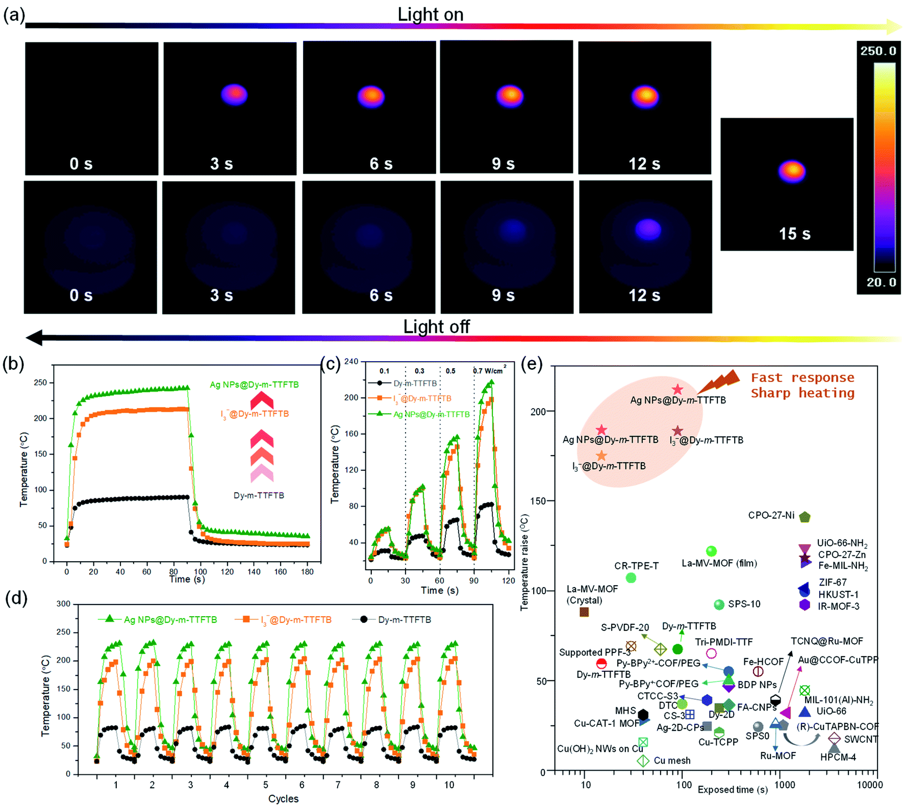 | ||
| Fig. 4 Photothermal conversion study. (a) The IR thermal images of an AgNPs@Dy-m-TTFTB MOF pallet under a 0.7 W cm−2 808 nm laser, which was then turned off. (b) Photothermal conversion behavior of Dy-m-TTFTB, I3−@Dy-m-TTFTB, and Ag NPs@Dy-m-TTFTB powder under 0.7 W cm−2 808 nm laser irradiation within 90 seconds and the following 90 seconds for cooling. (c) The heating and cooling cycle under different energy power 808 nm lasers with the samples of Dy-m-TTFTB, I3−@Dy-m-TTFTB, and Ag NPs@Dy-m-TTFTB. (d) Anti-photobleaching properties of Dy-m-TTFTB, I3−@Dy-m-TTFTB, and Ag NPs@Dy-m-TTFTB during 10 heating/cooling cycles. (e) The temperature change for various solid-state photothermal materials reported in the references. | ||
Upon the oxidation of Dy-m-TTFTB by I2, the resulting material, I3−@Dy-m-TTFTB, exhibits improved NIR adsorption and photothermal properties. Under illumination with 0.1, 0.3, 0.5, and 0.7 W cm−2 808 nm lasers (Fig. S22 and S23†), the temperature of the samples rapidly increased from room temperature to 54.9, 100.4, 145.8, and 198.2 °C in 15 s, respectively (Fig. 4c). Notably, the generation of TTF˙+ as well as the better π-electron delocalization are beneficial for photothermal conversion. These characteristics suppress the photon emission process and improve the photothermal efficiency. In addition to the contribution of TTF˙+ radicals, the photothermal performance of the MOF derivatives could be further enhanced by the incorporation of Ag NPs. Ag NPs@Dy-m-TTFTB demonstrated a rapid temperature increase from room temperature to 55.2, 101.7, 156.4, and 217.3 °C in 15 s by the irradiation of 0.1, 0.3, 0.5, and 0.7 W cm−2 808 nm lasers, respectively (Fig. 4a and c). This result demonstrated that the TTF˙+ radicals and the plasma effect of the Ag NPs work together to enhance the photothermal response of the Ag NPs@ Dy-m-TTFTB composite. Furthermore, these compounds showed excellent photostability in cycling tests (Fig. 4d).
To study the contribution of Ag NPs, we carefully analyzed the concentration of TTF˙+ radicals in I3−@Dy-m-TTFTB and Ag NPs@Dy-m-TTFTB. Based on their formulae, 34% TTF is oxidized to TTF˙+ radicals in I3−@Dy-m-TTFTB, which is slightly higher than that in Ag NPs@Dy-m-TTFTB (31% TTF oxidized). Therefore, the higher photothermal performance of Ag NPs@Dy-m-TTFTB (temperature increase of 217.3 °C in 15 s) than I3−@Dy-TTFTB (temperature increase of 198.2 °C in 15 s) can be attributed to the effect of Ag NPs (Fig. 4b). It has been reported that Ag NPs exhibit surface plasmon resonance to achieve photothermal conversion.55,56 Although the plasmon resonance wavelength of Ag NPs (4.3 nm) is typically about 420 nm, modulating the shape, size and assembly of Ag NPs can expand the plasmon wavelength to the range of 320–1100 nm.57 We propose that the enhanced photothermal effect of Ag NPs@Dy-m-TTFTB can be attributed to the surface plasmon resonance of aggregated Ag NPs in the defect sites of the MOF lattice or on the surface of MOF particles (Fig. S24†). Furthermore, the enhancement in the photothermal conversion by Ag NPs also can be observed in a similar system. The photothermal conversion of Dy-TTF-MOF,39 I3−@Dy-TTF-MOF and Ag NPs@Dy-TTF-MOF at increased temperatures is 107.4, 147.5, and 163.0 °C in 60 s under the irradiation of a 0.7 W cm−2 808 nm laser, respectively (Fig. S25†). In summary, we believe that the photothermal effect of Ag NPs@Dy-m-TTFTB is mainly attributed to the TTF˙+ radical generated by Ag+ oxidation, while the Ag NPs enhance the photothermal conversion by surface plasmon resonance.
All the samples reached a steady temperature within ∼20 seconds under the irradiation of a 0.7 W cm−2 power 808 nm laser. After 90 s of irradiation, the temperature of Dy-m-TTFTB, I3−@Dy-m-TTFTB, and Ag NPs@ Dy-m-TTFTB reached 90.1, 213.0, and 239.8 °C, respectively. Given these results, Ag NPs@ Dy-m-TTFTB represents the best photothermal material reported to date in the literature to the best of our knowledge (Fig. 4e).58–63 Considering the good photothermal properties and high stability, these materials can be potentially applied in photothermal organic catalysis, photothermal therapy, water steam generation, and seawater treatment.
Conclusions
In summary, a redox-active MOF incorporated with a TTF dimer building block and Dy-carboxylate chains has been studied. The redox reaction between the framework and I2 or Ag+ significantly increases the light absorption ability by generating a stable TTF˙+ state. The immobilization of Ag NPs further enhanced the photothermal performance through plasmon resonance. The temperature of the optimized material, Ag NPs@Dy-m-TTFTB, increased from room temperature to 240 °C in 90 s through the excitation of an 808 nm laser with an energy power of 0.7 W cm−2. We believe that this strategy can be applied to other redox-active porous crystallized materials. This work indicates that charge transfer and plasmon resonance have led to synergetic enhancement in photothermal effects.Data availability
All experimental supporting data and procedures are available in the ESI.†Author contributions
J. Z., H. Z., J. S., and S. Y. conceived and designed the project. J. S., P. C., S. Y., T. Y., and Z. Y. performed the experiments. S. Y., J. S., and J. Z. drafted the original manuscript. All authors have discussed the results and given approval to the manuscript.Conflicts of interest
There are no conflicts to declare.Acknowledgements
This work was supported by the National Basic Research Program of China (2018YFA0306004) and the National Natural Science Foundation of China (No. 21631006 and 21875099). This work was also supported by the Robert A. Welch Foundation through a Welch Endowed Chair to H.-C. Z. (A-0030). The support of the US Department of Energy, National Energy Technology Laboratory through NETL-Penn State University Coalition for Fossil Energy Research (UCFER, Contract No. DE-FE0026825) is gratefully acknowledged. The authors acknowledge Dr Hannah F. Drake for proofreading and revisions of the manuscript.Notes and references
- O. Neumann, C. Feronti, A. D. Neumann, A. Dong, K. Schell, B. Lu, E. Kim, M. Quinn, S. Thompson, N. Grady, P. Nordlander, M. Oden and N. J. Halas, Proc. Natl. Acad. Sci. U. S. A., 2013, 110, 11677–11681 CrossRef CAS PubMed.
- C. Xu and K. Pu, Chem. Soc. Rev., 2021, 50, 1111–1137 RSC.
- B.-D. Zheng, Q.-X. He, X. Li, J. Yoon and J.-D. Huang, Coord. Chem. Rev., 2021, 426, 213548 CrossRef CAS.
- H. Phan, T. S. Herng, D. Wang, X. Li, W. Zeng, J. Ding, K. P. Loh, A. T. Shen Wee and J. Wu, Chem, 2019, 5, 1223–1234 CAS.
- D. Jaque, L. Martinez Maestro, B. del Rosal, P. Haro-Gonzalez, A. Benayas, J. L. Plaza, E. Martin Rodriguez and J. Garcia Sole, Nanoscale, 2014, 6, 9494–9530 RSC.
- J. Liang, H. Liu, J. Yu, L. Zhou and J. Zhu, Nanophotonics, 2019, 8, 771–786 Search PubMed.
- N. Xu, P. Zhu, Y. Sheng, L. Zhou, X. Li, H. Tan, S. Zhu and J. Zhu, Joule, 2020, 4, 347–358 CrossRef.
- P. Tao, G. Ni, C. Song, W. Shang, J. Wu, J. Zhu, G. Chen and T. Deng, Nat. Energy, 2018, 3, 1031–1041 CrossRef.
- L. Zhou, Y. Tan, J. Wang, W. Xu, Y. Yuan, W. Cai, S. Zhu and J. Zhu, Nat. Photonics, 2016, 10, 393–398 CrossRef CAS.
- D. Mateo, J. L. Cerrillo, S. Durini and J. Gascon, Chem. Soc. Rev., 2021, 50, 2173–2210 RSC.
- J. D. Xiao and H. L. Jiang, Acc. Chem. Res., 2019, 52, 356–366 CrossRef CAS PubMed.
- J. F. Lovell, C. S. Jin, E. Huynh, H. Jin, C. Kim, J. L. Rubinstein, W. C. Chan, W. Cao, L. V. Wang and G. Zheng, Nat. Mater., 2011, 10, 324–332 CrossRef CAS.
- S. Gao, G. Wei, S. Zhang, B. Zheng, J. Xu, G. Chen, M. Li, S. Song, W. Fu, Z. Xiao and W. Lu, Nat. Commun., 2019, 10, 2206 CrossRef PubMed.
- G. Chen, J. Sun, Q. Peng, Q. Sun, G. Wang, Y. Cai, X. Gu, Z. Shuai and B. Z. Tang, Adv. Mater., 2020, 32, e1908537 CrossRef PubMed.
- H. Li, H. Wen, Z. Zhang, N. Song, R. T. K. Kwok, J. W. Y. Lam, L. Wang, D. Wang and B. Z. Tang, Angew. Chem., Int. Ed., 2020, 59, 20371–20375 CrossRef CAS.
- J. S. Ni, X. Zhang, G. Yang, T. Kang, X. Lin, M. Zha, Y. Li, L. Wang and K. Li, Angew. Chem., Int. Ed., 2020, 59, 11298–11302 CrossRef CAS.
- H. V. Schroder, F. Stein, J. M. Wollschlager, S. Sobottka, M. Gaedke, B. Sarkar and C. A. Schalley, Angew. Chem., Int. Ed., 2019, 58, 3496–3500 CrossRef PubMed.
- J. Yang, J. Choi, D. Bang, E. Kim, E. K. Lim, H. Park, J. S. Suh, K. Lee, K. H. Yoo, E. K. Kim, Y. M. Huh and S. Haam, Angew. Chem., Int. Ed., 2011, 50, 441–444 CrossRef CAS.
- Z. Zha, X. Yue, Q. Ren and Z. Dai, Adv. Mater., 2013, 25, 777–782 CrossRef CAS PubMed.
- H. C. Ma, G. J. Chen, F. Huang and Y. B. Dong, J. Am. Chem. Soc., 2020, 142, 12574–12578 CrossRef CAS PubMed.
- H.-C. Ma, C.-C. Zhao, G.-J. Chen and Y.-B. Dong, Nat. Commun., 2019, 10, 3368 CrossRef PubMed.
- Z. Mi, P. Yang, R. Wang, J. Unruangsri, W. Yang, C. Wang and J. Guo, J. Am. Chem. Soc., 2019, 141, 14433–14442 CrossRef CAS PubMed.
- X. Li, W. Xu, M. Tang, L. Zhou, B. Zhu, S. Zhu and J. Zhu, Proc. Natl. Acad. Sci. U. S. A., 2016, 113, 13953–13958 CrossRef CAS PubMed.
- H. Ghasemi, G. Ni, A. M. Marconnet, J. Loomis, S. Yerci, N. Miljkovic and G. Chen, Nat. Commun., 2014, 5, 4449 CrossRef CAS PubMed.
- D. Elmaghraoui, A. Politano and S. Jaziri, J. Chem. Phys., 2020, 152, 114102 CrossRef CAS PubMed.
- I.-W. Un and Y. Sivan, J. Appl. Phys., 2019, 126, 173103 CrossRef.
- X. He, X. He, S. Li, K. Zhuo, W. Qin, S. Dong, J. Chen, L. Ren, G. Liu and H. Xia, Polym. Chem., 2017, 8, 3674–3678 RSC.
- J. Espin, L. Garzon-Tovar, A. Carne-Sanchez, I. Imaz and D. Maspoch, ACS Appl. Mater. Interfaces, 2018, 10, 9555–9562 CrossRef CAS PubMed.
- J. Espin, L. Garzon-Tovar, G. Boix, I. Imaz and D. Maspoch, Chem. Commun., 2018, 54, 4184–4187 RSC.
- B. Lu, Y. Chen, P. Li, B. Wang, K. Mullen and M. Yin, Nat. Commun., 2019, 10, 767 CrossRef CAS PubMed.
- Q. Ma, P. Yin, M. Zhao, Z. Luo, Y. Huang, Q. He, Y. Yu, Z. Liu, Z. Hu, B. Chen and H. Zhang, Adv. Mater., 2019, 31, 1808249 CrossRef PubMed.
- J. Su, N. Xu, R. Murase, Z. M. Yang, D. M. D'Alessandro, J. L. Zuo and J. Zhu, Angew. Chem., Int. Ed., 2021, 60, 4789–4795 CrossRef CAS PubMed.
- M. Zhao, Y. Wang, Q. Ma, Y. Huang, X. Zhang, J. Ping, Z. Zhang, Q. Lu, Y. Yu, H. Xu, Y. Zhao and H. Zhang, Adv. Mater., 2015, 27, 7372–7378 CrossRef CAS PubMed.
- M. Q. Li, M. Zhao, L. Y. Bi, Y. Q. Hu, G. Gou, J. Li and Y. Z. Zheng, Inorg. Chem., 2019, 58, 6601–6608 CrossRef CAS PubMed.
- Q. Yang, Q. Xu, S. H. Yu and H. L. Jiang, Angew. Chem., Int. Ed., 2016, 55, 3685–3689 CrossRef CAS PubMed.
- Y. Z. Chen, Z. U. Wang, H. Wang, J. Lu, S. H. Yu and H. L. Jiang, J. Am. Chem. Soc., 2017, 139, 2035–2044 CrossRef CAS PubMed.
- H.-Y. Wang, L. Cui, J.-Z. Xie, C. F. Leong, D. M. D'Alessandro and J.-L. Zuo, Coord. Chem. Rev., 2017, 345, 342–361 CrossRef CAS.
- L. S. Xie, G. Skorupskii and M. Dinca, Chem. Rev., 2020, 120, 8536–8580 CrossRef CAS.
- J. Su, T. H. Hu, R. Murase, H. Y. Wang, D. M. D'Alessandro, M. Kurmoo and J. L. Zuo, Inorg. Chem., 2019, 58, 3698–3706 CrossRef CAS PubMed.
- J. Su, S. Yuan, J. Li, H. Y. Wang, J. Y. Ge, H. F. Drake, C. F. Leong, F. Yu, D. M. D'Alessandro, M. Kurmoo, J. L. Zuo and H. C. Zhou, Chem.–Eur. J., 2021, 27, 622–627 CrossRef CAS PubMed.
- J. Castells-Gil, S. Manas-Valero, I. J. Vitorica-Yrezabal, D. Ananias, J. Rocha, R. Santiago, S. T. Bromley, J. J. Baldovi, E. Coronado, M. Souto and G. Minguez Espallargas, Chem.–Eur. J., 2019, 25, 12636–12643 CrossRef CAS PubMed.
- L. S. Xie, E. V. Alexandrov, G. Skorupskii, D. M. Proserpio and M. Dinca, Chem. Sci., 2019, 10, 8558–8565 RSC.
- S. S. Park, E. R. Hontz, L. Sun, C. H. Hendon, A. Walsh, T. Van Voorhis and M. Dinca, J. Am. Chem. Soc., 2015, 137, 1774–1777 CrossRef CAS PubMed.
- A. L. Spek, Acta Crystallogr., Sect. C: Struct. Chem., 2015, 71, 9–18 CrossRef CAS PubMed.
- A. L. Spek, J. Appl. Crystallogr., 2003, 36, 7–13 CrossRef CAS.
- M. Yoshizawa, K. Kumazawa and M. Fujita, J. Am. Chem. Soc., 2005, 127, 13456–13457 CrossRef CAS PubMed.
- J. Lyskawa, M. Salle, J. Y. Balandier, F. Le Derf, E. Levillain, M. Allain, P. Viel and S. Palacin, Chem. Commun., 2006, 2233–2235 RSC.
- J. Tauc, R. Grigorovici and A. A. Vancu, Phys. Status Solidi B, 1966, 15, 627–637 CrossRef CAS.
- J. Su, W. He, X.-M. Li, L. Sun, H.-Y. Wang, Y.-Q. Lan, M. Ding and J.-L. Zuo, Matter, 2020, 2, 711–722 CrossRef.
- C. F. Leong, C.-H. Wang, C. D. Ling and D. M. D'Alessandro, Polyhedron, 2018, 154, 334–342 CrossRef CAS.
- S. Ma, S. M. Islam, Y. Shim, Q. Gu, P. Wang, H. Li, G. Sun, X. Yang and M. G. Kanatzidis, Chem. Mater., 2014, 26, 7114–7123 CrossRef CAS.
- H. R. Moon, J. H. Kim and M. P. Suh, Angew. Chem., Int. Ed., 2005, 44, 1261–1265 CrossRef CAS PubMed.
- J. Su, S. Yuan, T. Wang, C. Lollar, J.-L. Zuo, J. Zhang and H.-C. Zhou, Chem. Sci., 2020, 11, 1918–1925 RSC.
- Y. D. Huang, P. Huo, M. Y. Shao, J. X. Yin, W. C. Shen, Q. Y. Zhu and J. Dai, Inorg. Chem., 2014, 53, 3480–3487 CrossRef CAS PubMed.
- Y. N. Liu, F. Li, Z. R. Guo, Y. Q. Xiao, Y. L. Zhang, X. Y. Sun, T. T. Zhe, Y. Y. Cao, L. Wang, Q. Y. Lu and J. H. Wang, Chem. Eng. J., 2020, 382, 122990 CrossRef CAS.
- C. Nie, P. Du, H. W. Zhao, H. N. Xie, Y. X. Li, L. Yao, Y. Y. Shi, L. N. Hu, S. Y. Si, M. N. Zhang, J. W. Gu, L. Luo and Z. C. Sun, Chem.–Asian J., 2020, 15, 148–155 CrossRef CAS PubMed.
- M. Rycenga, C. M. Cobley, J. Zeng, W. Y. Li, C. H. Moran, Q. Zhang, D. Qin and Y. N. Xia, Chem. Rev., 2011, 111, 3669–3712 CrossRef CAS PubMed.
- T. Yan, Y.-Y. Li, J. Su, H.-Y. Wang and J.-L. Zuo, Chem.–Eur. J., 2021, 27, 11050–11055 CrossRef CAS PubMed.
- J. Espin, L. Garzon-Tovar, A. Carne-Sanchez, I. Imaz and D. Maspoch, ACS Appl. Mater. Interfaces, 2018, 10, 9555–9562 CrossRef CAS PubMed.
- Q. Ma, P. Yin, M. Zhao, Z. Luo, Y. Huang, Q. He, Y. Yu, Z. Liu, Z. Hu, B. Chen and H. Zhang, Adv. Mater., 2019, 31, 1808249 CrossRef PubMed.
- Z. He, L. Zhao, Q. Zhang, M. Chang, C. Li, H. Zhang, Y. Lu and Y. Chen, Adv. Funct. Mater., 2020, 30, 1910301 CrossRef CAS.
- Z. Mi, P. Yang, R. Wang, J. Unruangsri, W. Yang, C. Wang and J. Guo, J. Am. Chem. Soc., 2019, 141, 14433–14442 CrossRef CAS PubMed.
- Y. Wang, W. Zhu, W. Du, X. Liu, X. Zhang, H. Dong and W. Hu, Angew. Chem., Int. Ed., 2018, 57, 3963–3967 CrossRef CAS PubMed.
Footnote |
| † Electronic supplementary information (ESI) available. CCDC 1914386 and 2095766. For ESI and crystallographic data in CIF or other electronic format see DOI: 10.1039/d1sc07001k |
| This journal is © The Royal Society of Chemistry 2022 |