
 Open Access Article
 This Open Access Article is licensed under a Creative Commons Attribution-Non Commercial 3.0 Unported Licence
Multi-parametric functional imaging of cell cultures and tissues with a CMOS microelectrode array†
Jeffrey
Abbott
 abc,
Avik
Mukherjee
d,
Wenxuan
Wu
a,
Tianyang
Ye
ab,
Han Sae
Jung
a,
Kevin M.
Cheung
b,
Rona S.
Gertner
b,
Markus
Basan
*d,
Donhee
Ham
*a and
Hongkun
Park
*bc
abc,
Avik
Mukherjee
d,
Wenxuan
Wu
a,
Tianyang
Ye
ab,
Han Sae
Jung
a,
Kevin M.
Cheung
b,
Rona S.
Gertner
b,
Markus
Basan
*d,
Donhee
Ham
*a and
Hongkun
Park
*bc
aJohn A. Paulson School of Engineering and Applied Sciences, Harvard University, Cambridge, MA, USA. E-mail: donhee@seas.harvard.edu
bDepartment of Chemistry and Chemical Biology, Harvard University, Cambridge, Massachusetts, USA. E-mail: hongkun_park@harvard.edu
cDepartment of Physics, Harvard University, Cambridge, Massachusetts, USA
dDepartment of System Biology, Harvard Medical School, Boston, Massachusetts, USA. E-mail: markus@hms.harvard.edu
First published on 10th March 2022
Abstract
Electrode-based impedance and electrochemical measurements can provide cell-biology information that is difficult to obtain using optical-microscopy techniques. Such electrical methods are non-invasive, label-free, and continuous, eliminating the need for fluorescence reporters and overcoming optical imaging's throughput/temporal resolution limitations. Nonetheless, electrode-based techniques have not been heavily employed because devices typically contain few electrodes per well, resulting in noisy aggregate readouts. Complementary metal-oxide-semiconductor (CMOS) microelectrode arrays (MEAs) have sometimes been used for electrophysiological measurements with thousands of electrodes per well at sub-cellular pitches, but only basic impedance mappings of cell attachment have been performed outside of electrophysiology. Here, we report on new field-based impedance mapping and electrochemical mapping/patterning techniques to expand CMOS-MEA cell-biology applications. The methods enable accurate measurement of cell attachment, growth/wound healing, cell–cell adhesion, metabolic state, and redox properties with single-cell spatial resolution (20 μm electrode pitch). These measurements allow the quantification of adhesion and metabolic differences of cells expressing oncogenes versus wild-type controls. The multi-parametric, cell-population statistics captured by the chip-scale integrated device opens up new avenues for fully electronic high-throughput live-cell assays for phenotypic screening and drug discovery applications.
Introduction
Cell-based assays are essential tools for biomedical research and high-throughput drug discovery1,2 because they enable the investigation of cellular responses in a more physiologically relevant setting compared to conventional target-based assays. In particular, high-content phenotypic screening has undergone a resurgence recently,3 fueled by improvements in microscopy-based, multi-parametric data extraction.4–8 The spatial image information enables the characterization of heterogeneity in cell populations, an important concept for diverse diseases such as cancer9 and autoimmune diseases.10–12The current workhorse in cell-based assays is fluorescence microscopy because it provides sub-cellular resolution and culture-wide fields of view. In this detection modality, the throughput and temporal resolution of an assay are restricted by microscope speed. Moreover, phenotypic assays are limited by the availability of fluorescent reporters and their introduction/transfection into cells, which can pose experimental challenges depending on the cell types.13
To complement optical techniques, electrical14,15 and electrochemical techniques have long been used to monitor cell cultures.16 These measurements are label-free and provide easy access to important physiological parameters that are difficult to measure optically, such as the cell redox potential,17–19 cell–cell adhesion,20,21 and real-time kinetics. Unfortunately, electrode-based devices used in biological research to date typically use either large wire electrodes or just a few electrodes patterned on a substrate,14,15 leading to aggregate readouts that lack spatial information on cell/tissue heterogeneity. For instance, in transepithelial electrical resistance (TEER) measurements, cell–cell adhesion in an epithelial layer is characterized through impedance measurements between two macroscopic electrodes on either side of a cell sheet. Because current takes the path of least resistance, any hole in the cell layer (from sparse cell coverage or cell death/motility) shunts the measurement, thus misrepresenting the true integrity of most epithelial cells in the culture.
Here, we demonstrate high-resolution, high-throughput functional imaging of live-cell cultures via in situ impedance and electrochemical measurements using complementary metal-oxide-semiconductor (CMOS) microelectrode arrays (MEAs).22–34 We show that CMOS-MEAs allow label-free and non-invasive (non-destructive) tracking of cell growth dynamics and accurate measurements of cell-substrate/cell–cell adhesion and metabolic state. The 64 × 64 = 4096 electrode array's 20 μm electrode pitch, covering a total area of 1.3 × 1.3 mm2, enables electrical ‘imaging’ as well as measurement of cell population statistics – a feature not accomplished by whole-well readouts. The same experimental platform also enables tissue patterning and all-electronic wound healing assays.35,36 Using the Madin–Darby canine kidney (MDCK) cells as a model system, we demonstrate that our functional imaging platform is capable of detecting differences in cell–cell and cell-substrate adhesion; differences in extracellular redox potential at the growing edge and the interior of MDCK colony; and population differences in cell–cell adhesion and metabolic state between normal and RasV12-expressing37,38 MDCK cell lines.
The technology introduced in this work can be readily adapted into miniaturized devices that allow continuous, label-free, high-resolution functional assays of living cells and tissues. The multi-parametrics acquired in our device can replace multiple existing assay modalities (e.g., impedance, electrochemical, & optical fluorescence-based viability) while the spatial mapping capability provides heterogeneity information for increased accuracy like optical microscopy-based readout. Given that metabolic state and cell adhesion play key roles in diseased epithelium39,40 (e.g., inflammatory bowel diseases, celiac disease) and cancer,41,42 the CMOS-MEA platform reported here should provide a new means for low-cost, high-throughput, accurate phenotypic screening for related research and drug discovery applications.
Results
CMOS MEA for real-time, functional imaging of living cells
We use CMOS integrated circuits (ICs) to acquire three parameters relevant for live-cell assessment (Fig. 1a): cell-substrate impedance, Zs (characterizing cell attachment and cell-substrate adhesion), transepithelial impedance, Zte, (reflecting cell–cell adhesion and the integrity and barrier function of the cell monolayer), and extracellular redox potential, Vredox (indicative of the cellular metabolic state and respiration). Our custom-designed CMOS IC29,30,43 parallelizes impedance and electrochemical capabilities across a 64 × 64 array of electrodes (Fig. 1b–d). A fluidic well is packaged on top of the chip to culture cells, and the whole device is mounted below a top-down fluorescence microscope for simultaneous optical and electrical measurements (Fig. 1b and S1a and b†). At the center of the device sits an array of electrodes that consists of 8 μm diameter Pt electrodes spaced at a 20 μm pitch for single- or few-cell resolution (Fig. 1c). The total sensing area is 1.26 × 1.26 mm2. The remainder of the surface is insulated with silicon nitride. For long-term measurements, an integrated temperature sensor and heater adjacent the electrode array regulate the cells to 35–37 °C (see Fig. S1c† for a device micrograph); a mini-incubation chamber is placed over the device to regulate CO2 to 5% (Fig. S1e and f†).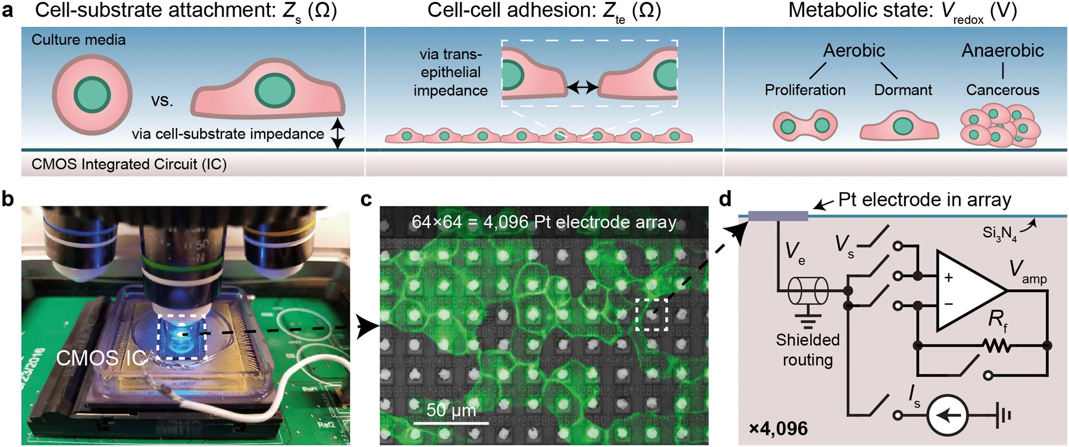 | ||
| Fig. 1 Real-time cell measurements using a CMOS microelectrode array (MEA) and imaging system. a, Three cell parameters are electrically measured using a complementary metal-oxide-semiconductor (CMOS) integrated circuit (IC) for live-cell assessment. b, A fluorescent microscope can be paired with the packaged CMOS IC for simultaneous optical and electrical cell measurement as well as a pseudo reference electrode, Pt (shown) or Ag/AgCl. c, Fluorescent image of Madin–Darby canine kidney (MDCK) epithelial cells cultured on top of the CMOS microelectrode array (MEA). d, Each of the 4096 Pt electrodes is connected its own peripheral circuit via a shielded routing (∼1–10 mm). The op-amp based circuit can be configured to apply a voltage via Vs and measure a current via a feedback resistor Rf (∼100 MΩ), or to apply a current via Is and buffer/measure the electrode voltage, Ve. The output of the op-amp, Vamp, is routed off-chip for analog-to-digital conversion. The switches are digitally programed using a real-time software interface. | ||
Each electrode in the array, or pixel, is connected to its own circuit that is highly configurable and programmable via a digital interface (Fig. 1d). The heart of this pixel circuit is an operational amplifier which can be configured as a buffer for electrode voltage (Ve) measurement, or as a transimpedance amplifier for electrode current (Ie) measurement. We described the details of these circuit configurations in a previous publication43 with respect to electrophysiological recording of neurons, a separate application of the device.29,30 The uniqueness of our CMOS-MEA lies in the high channel count (4096) and high spatial resolution (20 μm) that enables single-cell-resolution imaging as well as parallel current and open-circuit potential measurements, thus differing from previous MEA devices that measured high-frequency (≫1 MHz) electrode capacitance,23,32–34 voltage (with high-pass filters to block DC signals),24–27 current with a small number of channels (<32),24–26,31 or electrochemical devices with large electrode pitches (100 μm).31 For the cell-substrate and transepithelial impedance measurements, we configure the operational amplifiers into a transimpedance amplifier configuration to measure the electrodes current with a gain of 94 MΩ and a bandwidth of 30 kHz (Fig. S1d†).
Cell attachment mapping and wound healing assay via cell-substrate impedance, Zs
Alternating current (AC) impedance measurements between a pair of electrodes can be used to detect cells because cell membranes are more insulating than culture media. In a classic impedance measurement, however, solution paths around the cells shunt the measurement, lowering detection sensitivity. We improve the detection sensitivity of our device by instead measuring a change of electric field distribution due to the cells. Specifically, an AC voltage (1.8 kHz frequency/200 mV amplitude) is applied to a stimulation electrode with other electrodes grounded, and the return currents are measured via transimpedance amplifiers (Fig. 2a and b). To generate a map, the stimulation is scanned sequentially across the array (40 s per scan), and nearest neighbor cross-electrode currents are used to calculate a cell-substrate impedance, Zs (see Fig. S2 and ESI† Discussion 1 for the impedance model and calculation). Our technique extends previous CMOS IC-based proximity capacitive measurements at high frequency (≫1 MHz):32–34 the grounding of all electrodes (not just nearest neighbors) creates arcing field lines terminating across the electrode array (e.g., Fig. S2a†). At low frequency, a cell with its high-impedance membrane will affect this return distribution even if the stimulation electrode's direct impedance to the solution is not affected. Therefore, the field technique overcomes the typical limitations of Debye screening and allows cell impedances to be extracted (<1 MHz).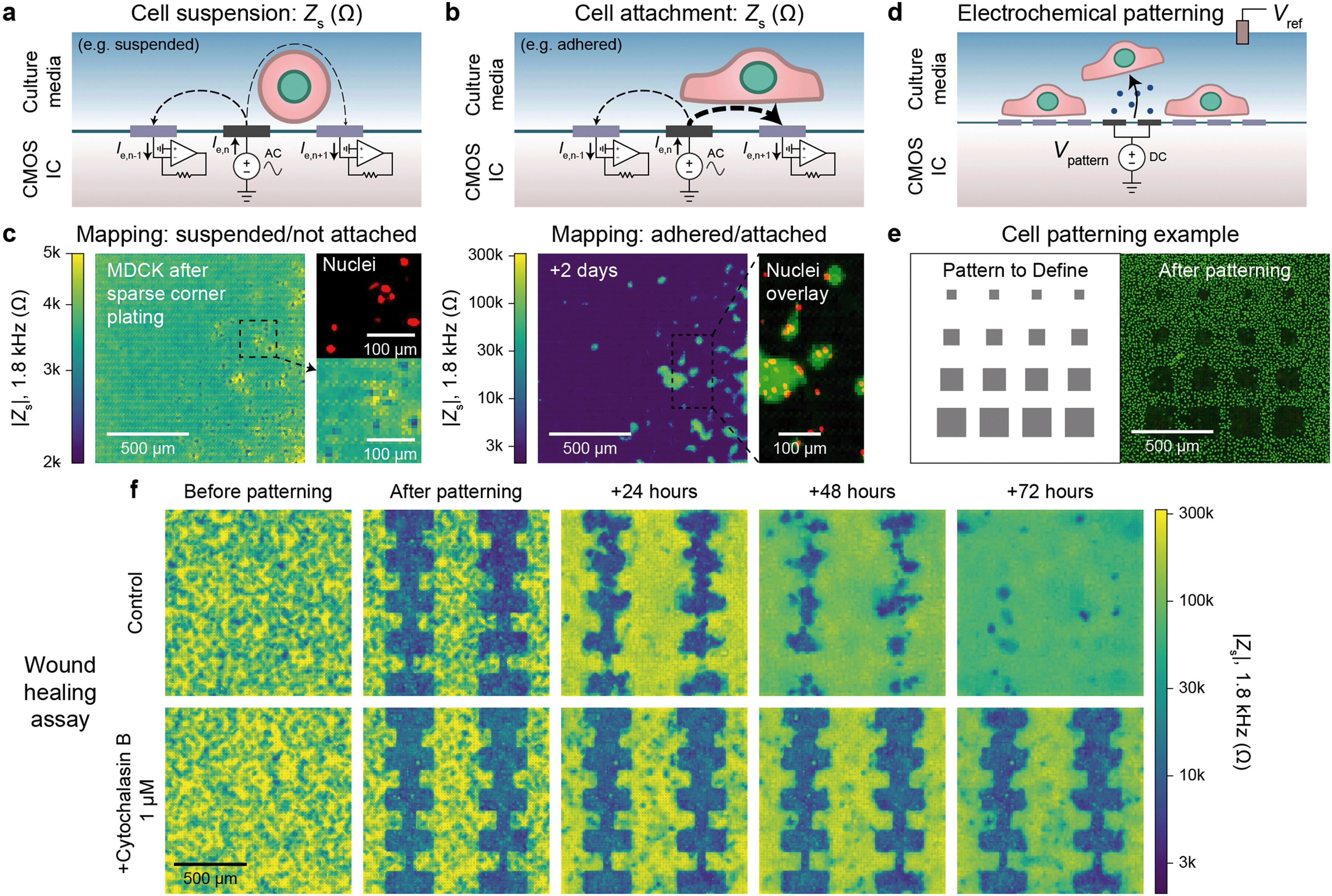 | ||
| Fig. 2 Electrically mapping and patterning cells using a CMOS electrode array for real time attachment and kinetics measurements. a and b, Cell attachment measurement schematics of a suspended/not attached cell (a) and adhered/attached cell (b). An AC voltage is applied to an electrode (n) with the remainder of the electrodes' (1, …, n − 1, n, n + 1, … 4096) currents measured via transimpedance amplifiers. The presence of a cell affects the field distribution in solution: an unattached cell blocks field lines decreasing cross-electrode coupling while an attached cell spanning two electrodes increases their coupling. To generate a cell map, the applied signal is scanned across the array (40 s per scan) and the cell-substrate impedance, Zs, is calculated (ESI† Discussion 1). c, The attachment of MDCK cells after a sparse corner plating was recorded via a Zs measurement every 7.5 min, see Video S1† for a full time course. d, Cells can be selectively removed from electrodes using electrochemically generated gas. A voltage, Vpattern, biased negative to produce H2 gas is commonly used (≤1.0 V versus Ag/AgCl). e, Various sized squares (left) were used for patterning MDCK cells and confirmed via a nuclei fluorescence image (right); a co-culture was further defined via a second plating, Fig. S4b.† f. Both mapping and patterning techniques were combined to form a wound healing kinetics assay. The healing was electrically mapped via Zs measurement once a day for a control (top) and drug (cytochalasin B) application (bottom); see Video S2† for a real-time regrowth example. Full healing was observed after 72 hours for the control while the culture treated with cytochalasin B showed almost no cell migration or growth. | ||
As a concrete example, a suspended cell blocks field lines in solution and lowers the nearest neighbor coupling (Fig. 2a), as confirmed by the data in Fig. 2c, left. In this measurement immediately following a plating of suspended MDCK cells, we observe smaller Zs from the electrodes on top of which the cells are located (∼2 kΩ) in comparison to non-covered electrodes (∼4 kΩ) confirmed via fluorescence microscopy of cell nuclei (Fig. 2c, left). In contrast, a cell attached to the surface and covering both a stimulation and recording electrode will increase the cross-electrode coupling by blocking vertical field lines. As shown in Fig. 2c, right and S2b and c,†Zs increases by almost two orders of magnitude (>200 kΩ) after cell settling. A time course of the Fig. 2c experiment (with a time resolution of 5 min) indicates that the cell-attachment takes more than 5 hours (Video S1†). The technique is rapid and non-invasive, as indicated by the normal cell growth.14,15 Different cell lines including MDCK (Zs ∼ 200 kΩ), HEK 293FT (Zs ∼ 50 kΩ), and HeLa S3 (Zs ∼ 5 kΩ) were measured using the technique with good spatial correspondence to optical images (Fig. S3a and b†). We used ethylenediaminetetraacetic acid (EDTA), a chelator that removes Ca2+ needed for integrin-mediated attachment, as detachment/attachment control (Fig. S3c and d and Video S2†). Upon EDTA addition, the cells quickly detached over ∼50 min and re-attached over ∼200 min after washout, confirming that our devices can track detachment/attachment in real-time.
The cell attachment mapping also enables an all-electronic wound healing assay when paired with electrochemistry-based patterning techniques.44 This kinetics assay is widely used in cell biology45 to measure cell migration, growth, and motility and is normally achieved via a mechanically generated scratch. We can use the electrodes to controllably remove cells via electrochemical gas generation to pattern cell cultures (Fig. 2d, see also Fig. S4 and Video S3†)44 and map regrowth in real-time. The generated gas both perforates the cell membrane to induce cell death and helps to detach the cells – we optimized the protocol to avoid large bubble formation by performing a series of short, 5 s gas generation pulses each separated by ∼60 s to allow gas diffusion. Unlike previous works, however, we can create arbitrary cell patterns by choosing which electrodes to apply the cell-removal signal to (Fig. 2e and f). A typical cell culture took ∼3 days to fill in the wound (Video S4† for a time course of a culture healing from a different device than Fig. 2f; similar wound healing characteristics were measured on the multiple devices). When cytochalasin B (a well-known cell motility inhibitor) was added to a separate culture, almost no growth was observed (Fig. 2f, bottom), demonstrating the utility of the assay for drug screening applications. Impedance measurements were performed at a 5 min interval. This time interval is comparable to other impedance works using 15 min intervals15 and real-time, in-incubator, well-plate scanning optical techniques of 2 hours.36 Though our spatial resolution (20 μm) is lower in comparison that what is achievable using optical imaging (∼1 μm), the growth of the cell sheet can be clearly measured to allow for kinetics information to be extracted (e.g., confluency over time), similar to other works.15,36
Cell–cell adhesion mapping via transepithelial impedance, Zte
Cells in a culture not only attach to the surface but also to each other via cell–cell connections. The tightness of these connections defines the permeability of a cell sheet and is important for epithelial tissues that act as barriers of the body surfaces, internal organ linings, and other tissues. Classically, this barrier function is measured by TEER, an impedance measurement between two electrodes on either side of a cell sheet.20,21 Such measurements are not repeatable or accurate, however, as any hole in the sheet will contribute much more to the measured electrode-to-electrode current than the current through the cell sheet.With our device, we can substantially improve upon this technique by mapping the transepithelial impedance, Zte. Here, cell–cell connectivity is assessed/mapped using only electrodes covered by cells, thus mitigating the effects of any holes in cell sheets. Concretely, we measure the change of the vertical field above the electrode to best isolate the effects of the cell–cell connections. We use two circuit configurations: a fast (<1 s/measurement) parallel electrode measurement versus a reference (Fig. 3a, left) and a slower (40 s/measurement) measurement without a reference (Fig. 3a, right). The fast measurements are well suited for sweeps across multiple frequencies whereas the slower measurements are good for long-term measurements and device miniaturization. For both types of measurements, we use platinum black (PtB) deposition onto the Pt electrodes to lower Ze (by about 5×) to improve Zte sensitivity (Fig. S5a and b; see also ESI† Discussion 1 for the impedance model and calculation).
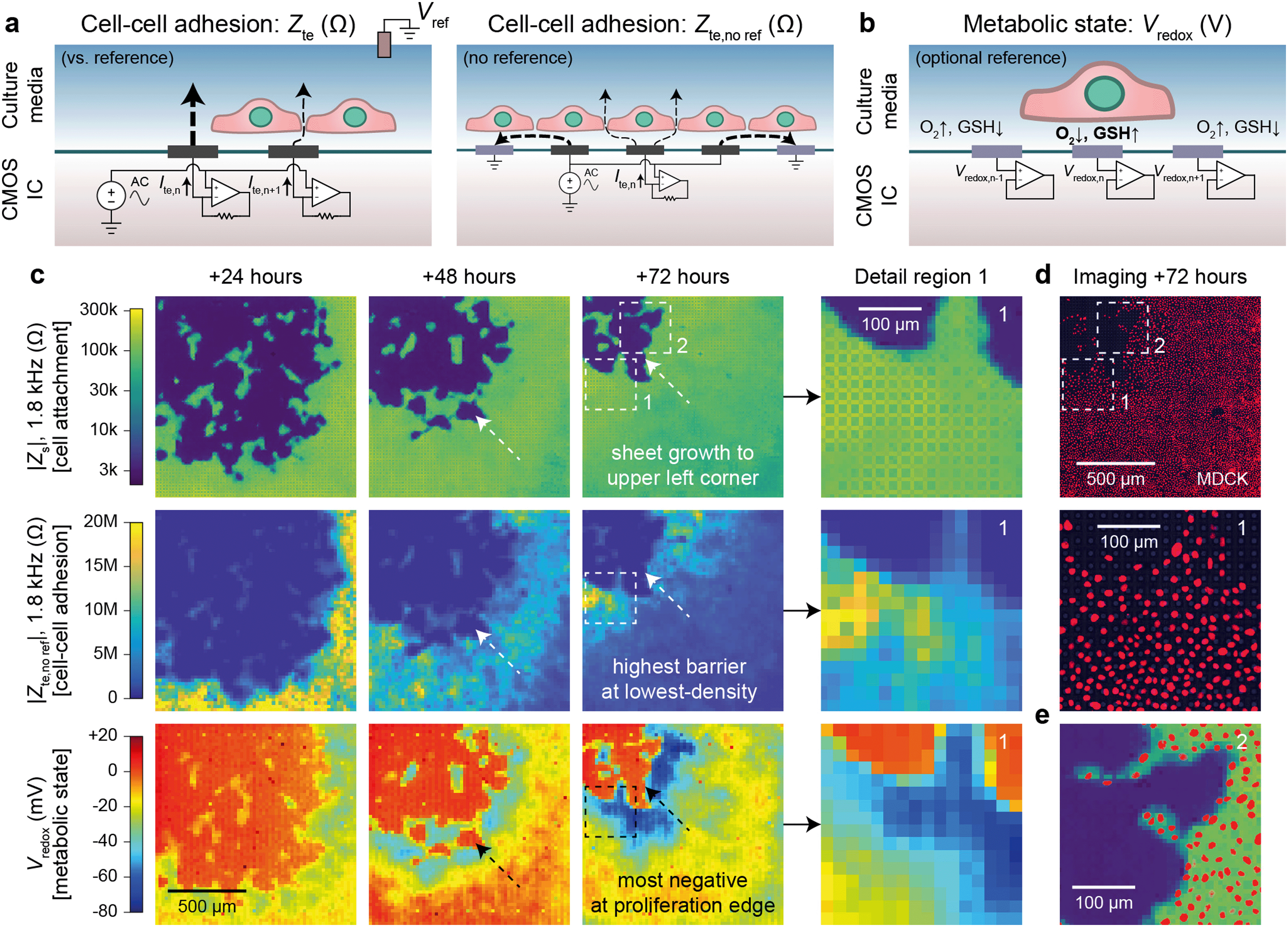 | ||
| Fig. 3 Transepithelial impedance and extracellular redox mapping multi-parametric measurements for label-free, non-invasive cell culture monitoring. a, Transepithelial impedance, Zte, measurement schematics for cell–cell adhesion quantification. Measurements can be made versus a grounded reference (left) by applying an AC voltage to all electrodes with the each transepithelial electrode current, Ite,n (n = 1, 2, …4096), measured via transimpedance amplifiers (measurement duration of 1 s/frequency). The resultant field distribution is vertically aligned with the connectivity of the cells decreasing the Ite. A non-reference measurement can be made (right) by applying an AC voltage to an electrode (n) and its neighboring electrodes to create an effective vertical field measurement with the remainder of the electrodes' grounded. To generate a cell map, the applied signal is scanned across the array (40 s per scan/frequency). The Zte can be extracted from either measurement (ESI† Discussion 1). b, Extracellular redox potential, Vredox, measurement schematic to measure the open circuit potential via the pixel amplifier configured as a buffer. c, Multi-parametric measurements of |Zs|, |Zte|, and Vredox at +24, +48, and +72 hours after MDCK cell plating to infer cell attachment (top), cell–cell adhesion (middle), and metabolic state (bottom). d, Nuclei fluorescence imaging at +72 hours after plating (top) and a detail region 1 comparison (bottom) show the lowest cell density on the leading edge in comparison to the trailing edge. e, A detail region 2 overlay of the cell nuclei and cell attachment shows good spatial correspondence with single-cell resolution. | ||
Fig. 3c shows a dual Zs–Zte measurement of a MDCK cell sheet growing over the array across three days (see also Fig. S6† for an additional example on a different device). From the cell attachment maps (Fig. 3c, top), the sheet grew from the bottom right to the upper left corner of the array, thus creating a natural difference in cell density (fluorescent nuclei image in Fig. 3e and density plot in Fig. S5d†). On the leading edge where cells proliferate, the cell density was smaller, but the cell barrier was higher due to fewer cell–cell boundaries (Fig. 3c, middle). As shown in the detail region 1 of Fig. 3c and d middle, Zte is the highest where the cell nuclei are most spaced apart (see also Fig. S5†). A significant decrease (20 MΩ to <10 MΩ) in Zte was also observed for MDCK cells during an oxygen purge that is known to disrupt structure polarity and lessen cell–cell connectivity46 (Fig. S7 and Video S5†).
Experiments across the frequency range showed that mid-range frequencies of ∼2 kHz to 5 kHz were best for assessing cell–cell connectivity in terms of contrast (Fig. S5b and c†) and for fitting the cell density information extracted from optical imaging (Fig. S5d and f†). We also found that flat/resistive TEER is best measured between ∼100 Hz to ∼10 kHz (Fig. S5b†). Below this frequency range (<100 Hz), the electrode capacitance dominates the measurement; the cell layer capacitance causes roll-off at higher (>10 kHz) frequencies.20,21 Furthermore, though we display our measurements in the units of Ohms (Ω), the data correspond well to existing literature20,21 by taking into consideration the effective unit area of each electrode [20 × 20 μm2]: dense MDCK regions measure from 10–20 MΩ [40–80 Ω cm2] and low-density regions at >100 MΩ [>400 Ω cm2] (Fig. S5a and b†).
These measurements demonstrate the importance of spatial resolution for measuring the barrier function because Zte itself can vary by more than ten times across a cell sheet in the same culture. A single sheet-wide TEER measurement can therefore greatly misrepresent cell–cell adhesion and make measurements much more susceptible to culture conditions (e.g. confluency, plating density, age of culture, oxygen concentration, etc.).
Inferring cell metabolic state by mapping extracellular redox potential, Vredox
Beyond impedance measurements, our electrode array can also be used for mapping extracellular redox potential, Vredox, in situ. We use the Pt electrodes directly underneath the cells for this measurement with the pixel amplifier configured as a buffer (Fig. 3b). The extracellular redox potential is determined by the balance between various redox species in the extracellular space. During aerobic metabolism, cells produce energy by oxidizing organic molecules (e.g., glucose) with O2. In this process, the redox potential of the cell is largely determined by a balance between O2 pulling the potential up (oxidizing) and glutathione (GSH) pulling the potential down (reducing).17 The redox environment is not only important for electron transfer, but also for neutralizing harmful reactive oxygen species,47 cell–cell signaling,48 and regulating the state of the cell.17–19 It also changes whether a cell is in a state of proliferation, differentiation, apoptosis, or necrosis.17We monitored proximate Vredox together with Zs and Zte during cell growth (Fig. 3c). A negative Vredox in the range of −30 mV to −80 mV was recorded for electrodes with cells on top (Fig. 3c, bottom; see also Fig. S6† for an additional example on a different device). The spatial distribution of Vredox is different from those of Zs and Zte: the most negative Vredox is at the leading edge and not the lowest density. To understand the factors contributing to Vredox, we performed a separate oxygen purge experiment and an oxidizing titration experiment. The oxygen purge experiment in Fig. S7 (Video S5†) shows the Vredox spatial distribution is eliminated upon removal of oxygen – indicating that low [O2] from cellular respiration contributes to the negative Vredox. The oxidizing titration in Fig. S8 (Video S6†) shows a high [GSH]/reducing capacity for electrodes with cells on top (>200 μM) in comparison to the media (4 μM). These experiments show that the negative signal of leading edge originates from both low [O2] (indicative of respiration) and high [GSH] (caused by cell proliferation).17 We note that the cells in the interior, which are not actively growing because they have reached confluence, exhibit a more positive Vredox. The −45 mV difference between proliferating cells (−70 mV) and interior confluent cells (−25 mV) is consistent with previous reports of a −34 mV difference based on oxidized/reduced glutathione measurements for human fibroblasts.17,49 The magnitude difference of our measurements may derive from additional oxygen contributions, cell type, and/or measurement method.
Combined Zs–Zte–Vredox measurements of an oncogene model cell line
The Zs, Zte, and Vredox measurements discussed so far provide information on the cell's attachment to the substrate and to other cells, as well as cells' local electrochemical environment. Cancer cells are known to exhibit distinct behaviors from normal cells because tumor development usually features structural polarity loss and accelerated growth via anaerobic Warburg metabolism. To demonstrate the utility of our technique in this context, we monitored a genetically modified MDCK cell line with tetracycline-induced RasV12 and GFP expression (RasV12 is a known oncogene,37,38 and GFP is used to assess expression using fluorescence measurements). Real-time cell attachment measurements revealed a marked decrease in attachment ∼48 h after tetracycline addition (Video S7†). We also observe a decrease in |Vredox| for cells at the leading edge (Fig. S9†), in stark contrast to the behavior observed in normal MDCK sheets (Fig. 3c).To quantify the differences, we performed a cross-corner plating of normal and RasV12 expressing MDCK cell lines, wherein the RasV12 was turned on more than 48 h before measurement (Fig. 4). The Zs–Zte–Vredox maps (Fig. 4a) and a fluorescence overlay (Fig. 4b) show a decrease in cell attachment (Zs), cell–cell adhesion (Zte), and Vredox for the RasV12 cells in the lower right in comparison to the normal cells on the upper left. The differences in adhesion and metabolic state for the distinct cell types can be seen in cell–cell adhesion/Zte across frequency (Fig. 4c) and an oxidizing titration experiment for metabolic state/Vredox (Fig. 4d and Video S8†). The cell differences are best summarized in plotting cell barrier at 2.5 kHz versus Vredox at zero oxidizing concentration, wherein distinct clusters are observed for the different cell types (Fig. 4e). The normal cells exhibit high impedance (large TEER signal) in the frequency range of ∼100 Hz to 5 kHz and show aerobic metabolism (negative redox signal) on both the interior and edges of the sheet with a median reducing capacity of ∼100 μM. In contrast the RasV12 cells exhibit lower impedance across the frequency range (albeit some outlier regions on the leading edge) with aerobic (anaerobic) metabolism for older (leading edge) cells. The overall reducing capacity is also smaller at ∼40 μM.
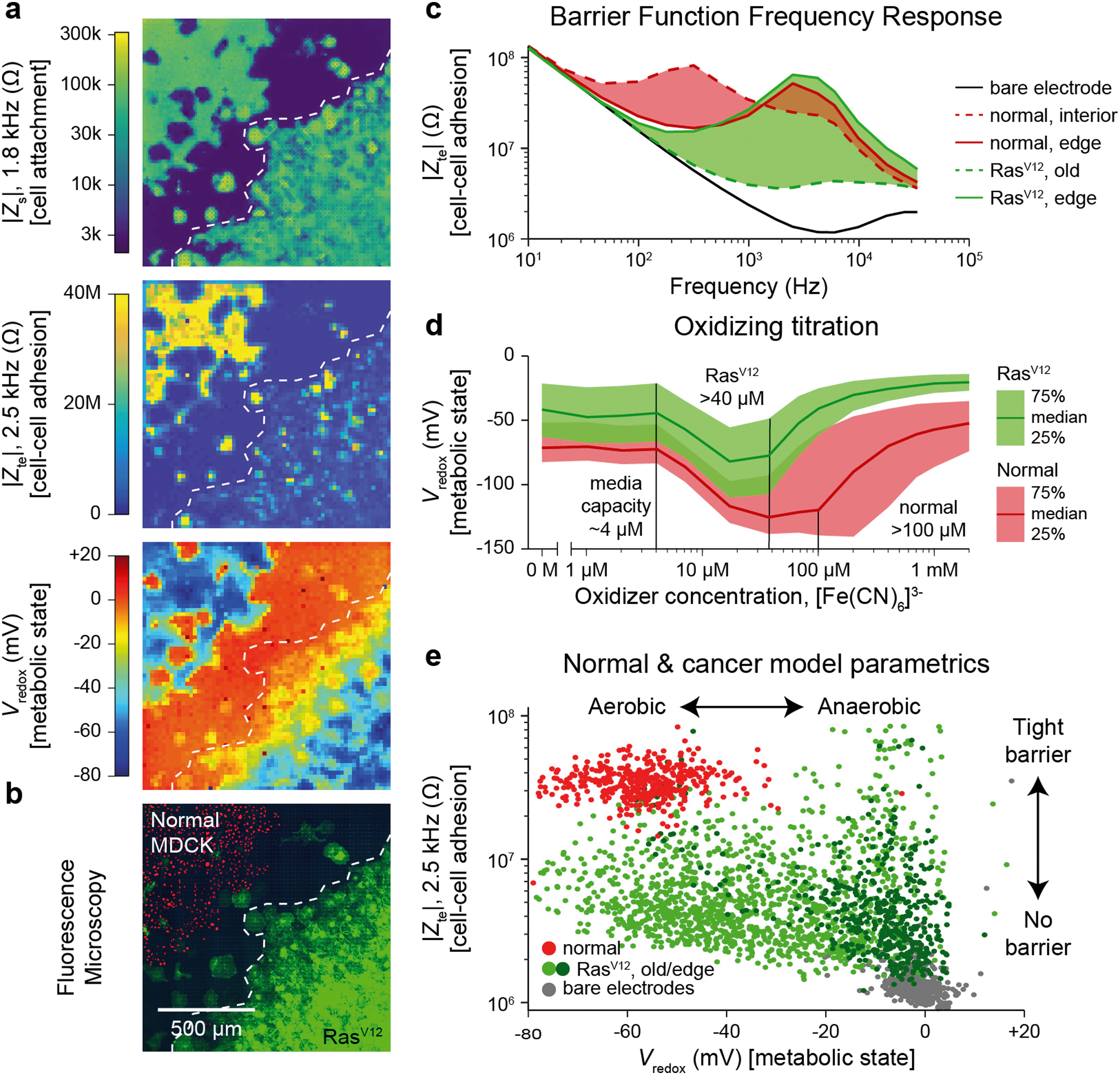 | ||
| Fig. 4 Multi-parametric measurement of MDCK cells expressing the RasV12 oncogene showing decreased cell–cell connectivity and Warburg metabolism. a and b, Multi-parametric measurements of |Zs|, |Zte|, and Vredox with normal MDCK cells (red nuclei, upper left corner in b) and MDCK cells expressing the RasV12 oncogene (green membrane, lower right corner in b), to infer cell attachment (a, top), cell–cell adhesion (a, middle), and metabolic state (a, bottom). c, Cell–cell adhesion measurements across frequency for representative pixels for the leading edge and interior cells of both cell types. d, The normal and RasV12 cancer model MDCK cells show different characteristics during a ferricyanide, [Fe(CN)6]3−, oxidizing titration. A time-course of the titration is shown in Video S8.† e, To highlight the parametric differences related to the RasV12 expression, a plot of the cell–cell adhesion and metabolic state shows distinct clustering of the normal MDCK (red) and old/edge RasV12 expressing MDCK (light/dark green) cells. | ||
The decreased cell-substrate and cell–cell adhesion for the RasV12-expressing MDCK cells corresponds well with previous works that described blocked formation of actin fibers/focal adhesions resulting in decreased cell-matrix adhesion.50 Likewise, the changes in metabolic state are associated with RasV12: an initial increase in oxygen consumption followed by a change to anaerobic metabolism embodying the Warburg phenotype.51 For further validation and exploration of redox signal contribution, we performed a luminescence-based GSH/GSSG assay and measured a significant ratio difference of GSH/GSSG of 49.4 ± 15.2 for normal versus 16.9 ± 6.3 for RasV12 expressing MDCK cells (mean ± standard deviation, Fig. S10†); an average Vredox difference of 17.5 mV was also calculated.17 This intracellular glutathione difference supports our results but does not account for the much larger redox potential difference (∼50 mV) observed in Fig. 4e for leading edge RasV12 growth cells. The remaining difference is attributed to our technique's additional sensitivity to the cells' oxygen consumption and the expected change of state to anaerobic metabolism for RasV12-expressing cells.51 This example shows the ability of our device to characterize cell barrier and metabolic state for cancer related phenotypic assays.
Discussion
The in situ techniques using CMOS-MEAs demonstrated in this work increase the accuracy of conventional impedance- and electrochemistry-based cell measurements. The field-based impedance technique offers improved sensitivity of cell-attachment assays compared to traditional techniques that measure a change of electrode impedance. Though we focus on monolayer cell sheets in our work here (estimated around ∼10 μm thick), the demonstrated techniques may enable three-dimensional analysis when suitably modified stimulation/grounded electrodes are used to create high arching fringing fields (e.g. Fig. S2a†). The cell–cell adhesion mapping technique (Fig. 3a, right) is a step towards this direction, where we measure just a vertical field to isolate the contribution of the cell–cell connections. An immediate future study could focus on how cell thickness and/or multiple layers of cell sheets affect the cell–cell adhesion measurement. Likewise, the cell patterning technique could be coupled with multiple platings to build complex, repeatable multi-cell cultures: as a simple example, we defined a co-culture of different MDCK cells (Fig. S4b†). Removal of cells on top of the array with single-cell resolution could also be used for selective removal of cell-heterogeneity or isolation of single cells.The cell–cell adhesion measurements show great promise for assessing barrier function more accurately than previous electrode-based techniques. Barrier function is known to degrade with diseases of the gut52 (e.g. inflammatory bowel diseases, celiac disease), allergic diseases with epithelial inflamation,53 and neurological diseases related to blood–brain barrier dysfunction.54 Current barrier function assays use either trans-well impedance measurements between a pair of macroscale electrodes on either side of a cell sheet20,21 or cross-electrode measurements between a pair of substrate integrated electrodes of large dimensions14,15 (>100 × 100 μm2). Both techniques are highly susceptible to cell culture conditions, especially sheet confluency. Creating an accurate, low-cost, barrier in a dish assay without the need for confluent cell sheets, could therefore benefit the functional screening of drug compounds or therapeutic techniques to help rectify barrier breakdown in these diseases.
The real-time, label-free, redox state mapping demonstrated here could find wide applications in drug screening and research related to metabolism where whole-well oxygen consumption rate (OCR) readouts are typically used. In contrast to the OCR techniques that provide aggregate signal readouts of 10![[thin space (1/6-em)]](https://www.rsc.org/images/entities/char_2009.gif) 000 to 100000 cells per well, our 20 μm resolution has ∼1000× more spatial information. This high-resolution metabolic information enables the assessment of the drug's metabolic impacts across all cell cycles and not just the mean state of the cell culture population. Additional studies on the effects of diffusion, observed during oxidizing titrations of Videos S6 and S8,† provide information on the redox flux of the cell sheet when paired with physical information of the cell-substrate gap. Beyond metabolism, similar assays can also be developed to determine cell death, as cells undergoing apoptosis or necrosis have a distinctly higher redox potential.17
000 to 100000 cells per well, our 20 μm resolution has ∼1000× more spatial information. This high-resolution metabolic information enables the assessment of the drug's metabolic impacts across all cell cycles and not just the mean state of the cell culture population. Additional studies on the effects of diffusion, observed during oxidizing titrations of Videos S6 and S8,† provide information on the redox flux of the cell sheet when paired with physical information of the cell-substrate gap. Beyond metabolism, similar assays can also be developed to determine cell death, as cells undergoing apoptosis or necrosis have a distinctly higher redox potential.17
The spatial information of our microelectrode array techniques improves accuracy beyond existing electrical and electrochemical tools, although it is still far from the sub-cellular imaging resolutions of optical techniques. We note that other electrode-based works have achieved <1 μm pitches,23,34 with high-frequency, capacitive measurements for detection. Our techniques can be extended to sub-cellular adhesion resolutions if combined with such dense arrays. We also note that our electrical/electrochemical technique is not capable of reading out fluorescence signals and therefore is limited in terms of its information content. Other works have moved towards adding fluorescence capabilities on CMOS chips.55
Overall, our measurement techniques are label-free, non-invasive, and demonstrated to effectively monitor live cell cultures over many days of culture. Based on CMOS IC technology, the driving force behind the semiconductor revolution over the past decades, we envision that these techniques can be packaged in small, plug and play devices for performing impedance and electrochemical assays affordably and at scale within research and drug development laboratories.
Methods
Chip design, fabrication, and packaging
We designed the custom CMOS integrated circuit (IC) and outsourced its fabrication in 0.18 μm technology to the United Microelectronics Corporation. Subsequently, we post-fabricated the platinum (Pt) electrodes on the surface aluminum pads of the CMOS IC in house.29 We used both planar pad electrodes and planar pad electrodes with platinum black (PtB), with the fabrication method described previously.29 After the electrode post-fabrication, the CMOS ICs were wire-bonded to chip carriers (Spectrum Semiconductor Materials, San Jose, CA). A glass inner and outer ring (Friedrich & Dimmock, Millville, NJ) were glued to the chip and chip carrier, respectively, using polydimethylsiloxane (PDMS). PDMS was then poured between these two glass rings to encapsulate the wire bonds. Cells were cultured in the well formed by the inner ring once the device was completed.Cell culture protocols
MDCK type II wildtype cells, and wildtype MDCK cell expressing nuclear GFP were a kind gift from the Eugenia Piddini lab (University of Bristol, UK). MDCK cells expressing nuclear mCherry (H2B:mCherry), were prepared in the Basan lab using the wildtype MDCK cells mentioned above. MDCK cells expressing tetracycline inducible RasG12V, were a kind gift from the Yasuyuki Fujita lab (Hokkaido University, Japan).MDCK cells (Wildtype and nuclear expressing) were cultured in low glucose DMEM (Gibco catalog no. 11054-001) in presence of 10% FBS (Gibco catalog no. 10437-028) and 1× GlutMax, (Gibco catalog no. 35050061). Cells were maintained in standard T25 and T75 flasks (BD) in a humidified incubator kept at 37 °C.
Tetracycline inducible MDCK line (RasG12V), was maintained in low glucose DMEM (Gibco catalog no. 11054-001) in presence of 10% Tet system approved FBS (Gibco catalog no. A4736401) and 1× GlutMax (Gibco catalog no. 35050061). RasG12V expression was induced by addition of tetracycline (10 μg ml−1), in the media.
The HEK293FT cells were acquired from Thermo Fisher (R70007) and the HeLa S3 cells were acquired from ATCC (CCL-2.2) and cultured in the recommended media conditions.
Electrical measurements were performed in the stated culture medias without a reference for most measurements except the patterning of Fig. 2 and S4,† the ferricyanide titration of Fig. S8,† and the cell barrier measurements of Fig. 4, which used a pseudo Ag/AgCl reference. All measurements were performed using the mini-incubator setup to regulate CO2 to 5% (Fig. S1†) except during fluorescence imaging. The temperature of the CMOS IC was set to 35 °C for experiments using the integrated temperature sensors and heater.
The devices were cleaned with trypsin, diluted Alconox and DI water after each cell culture and were then reused. Devices could be re-used for the experiments up to ∼200 days in solution and for ∼20 culture experiments. Before each cell plating, the devices were electrochemically cleaned via cyclic voltammetry using 40×, 200 mV s−1 scans cycled from +0.8 V to −1.0 V versus a Pt reference electrode in 1× PBS. Devices were then sprayed with 70% ethanol and transferred to a bio-hood, rinsed 5+ times in sterile DI water, and air dried in ambient conditions. The devices were then coated with 0.1% poly-d-lysine solution (Sigma-Aldrich P6407 and P7280, Atlanta, GA) dissolved in borate buffer, incubated at 4 °C overnight to form a cell-adhesive coating, and then washed six times and dried before cell plating.
Cell patterning and corner platings
Patterning was performed on the same day as the initial plating after cell attachment (3 h+). After patterning, the electrodes were electrochemically cleaned via the cyclic voltammetry protocol versus a Pt reference in culture media, a fresh media swap was then performed. For the co-culture of Fig. S4,† a second plating was performed after patterning and electrochemical cleaning in fresh media. To achieve the corner platings, a small droplet (∼15 μL) containing the cell amounts (typically 30–50 k cells/well) were carefully pipetted into a corner of the inner ring of the device; to allow the cells to settle a larger amount of media was only added after ∼1 h. To achieve the cross-corner plating's normal cells and RasV12 cells, small droplets (∼15 μL) were carefully pipetted into the opposite corners.Drug applications
For drug applications, a small amount of drug was added to ∼1.5 mL of media removed from the device's well via a pipette, thoroughly mixed in a plastic test tube, and pipetted back into the culture. For media swaps, media was poured out of the device such that a small amount (<100 μL) remained in the inner ring of the packaged device, and then 6 mL of fresh media was added. For the ferricyanide titrations of Fig. 4 and S8,† fresh stocks of sodium ferricyanide were made in 1× PBS at concentrations of 1 mM, 10 mM, and 100 mM. Small amounts of stock (6–20 μL) were then added to removed media, mixed, and injected back onto the device. Two measurements per concentration were typically made. Final drug concentrations are reported in figure captions where appropriate.PtB electrodeposition
PtB deposition on the Pt electrodes was performed with packaged devices, using the same experimental setup as in the experiments (Fig. S1†), as outlined in our previous publication.29 In short, electrodeposition was performed by cycling the electrodes' voltages from 0 V to −1.2 V versus a Pt reference electrode at a scan rate of 50 mV s−1 in a solution of 0.5 mM H2PtCl6 and 25 mM NaNO3. Typically, 10–20 cycles were performed to achieve the desired electrode impedance.Electrical recording and data analytics
Data was acquired using LabVIEW software and post-processed using MATLAB for visualization. A switched-capacitor feedback resistance, Rf in Fig. 1, of 94 MΩ (Fig. S1d†) was used for the transimpedance amplifier recordings.43 The cell attachment and cell barrier AC impedance measurements used a stimulation frequency synchronized with the amplifier sample frequency of ∼10 kHz, a fast Fourier transform was then used to extract out only the applied frequency. Frequencies above the sample frequency were aliased into the measured frequency range up to the ∼35 kHz bandwidth of the amplifier. For the Vredox measurements, typically 60 s of voltage data was acquired to allow for settling and the last ∼1 s of data of each pixel was averaged. To generate Vredox maps without a reference, the median value of electrodes without cells (determined from the cell attachment maps) were used as a reference.Time sequences were typically taken with 5 min to 10 min measurement intervals. For multi-parametric measurements, the three parameters' measurements were cycled within the 5–10 min; the fastest interval achievable is ∼160 s (∼3 min) to accomplish the two impedance measurements (40 s/measurement) and the redox measurement (60 s), with additional time for programming and electronic settling. Cell attachment (Zs) for cell mapping assays (e.g. wound healing assay, attachment) can be achieved with intervals as short as 1 min.
The cell attachment (Zs) image is generated through cross-electrode current measurements (see ESI† Discussion 1). An AC voltage application is scanned through the 4096 electrode array while currents in the remaining electrodes currents were measured. The 4095 measurements for each of the 4096 electrodes are placed into a 4096 × 4096 matrix of currents (with the diagonal filled with zero). The cross-electrode currents are pulled for calculating the 3 × 3 kernel via eqn (5)–(7) in ESI† Discussion 1 and according to the map in Fig. S2d,† and the total currents for each electrode are calculated by summing along the column. The result is placed into a 190 × 190 image matrix. The cross-electrode measurements are symmetric (causing duplication for adjacent pixel kernels) – we use this to up-sample effective measurement resolution using all 8 neighbor measurements (both nearest neighbor horizontal/vertical and diagonal). The grid artifacts (seen in Fig. 3 and S6†) come from the normalization factor of sqrt(2) in eqn (6) in ESI† Discussion 1 to account for the difference in distance diagonally in comparison to vertical/horizontal nearest neighbors. We estimate the effective measurement resolution for Zs to be 20 μm/sqrt(3) (∼11.5 μm) due to the 3 unique measurements per interior pixel.
The cell–cell adhesion image generated by a scanned measurement (Zte,no ref) uses only the scanned pixel's current (Fig. 3a) and the sum calculated via the Zs measurement for calculation via eqn (9) and (10) in ESI† Discussion 1 – the result is placed into a 63 × 63 image matrix (the outside edges are not used due to the lack of adjacent electrodes for the biasing scheme). The cell–cell adhesion using the reference (Zte) uses a single parallel measurement of the 4096 electrodes' currents to calculate Ztevia eqn (10) in ESI† Discussion 1 – the result is placed into a 64 × 64 image matrix.
Cell attachment (Zs) is logarithmically plotted in the perceptually uniform viridis color map from ∼3 kΩ to ∼300 kΩ to cover the non-attached to strong attached regimes for the different cell type used (e.g. Fig. S3†). It is adjusted in Fig. 2c to highlight the ability to measure suspended cells via a decreased Zs. Cell–cell adhesion (Zte) is plotted on a linear scale in the MATLAB color map of Parula from 0 Ω to 20–40 MΩ where we found most Zte values. The linear scale is chosen to give more contrast between high and low Zte regions. Redox state (Vredox) is plotted in the non-linear jet color map from MATLAB to help provide contrast between regions of potential and edges of cell sheets. As this measurement is mainly plotted as relative (places with cells versus places without cells) we chose not to use a three colormap linear map (e.g. blue-white-red).
Author contributions
H. P., D. H., M. B., J. A., A. M., W. W., T. Y., and K. M. C. conceived and designed the experiments. J. A. and W. W. designed the electronics, T. Y. and H. S. J. performed post-fabrication and device packaging, J. A., A. M., and R. S. G. performed the experiments, and J. A., A. M., W. W., T. Y., K. M. C., M. B., H. P. and D. H. analyzed the data. M. B., D. H., and H. P. supervised the project. J. A., A. M., M. B., D. H., and H. P. wrote the manuscript, and all authors read and discussed it.Conflicts of interest
H. P., D. H., J. A., and W. W. have co-founded a start-up company, CytoTronics Inc., to commercialize technologies involving CMOS microelectrode arrays for multi-parametric functional imaging of cell cultures and tissues.Acknowledgements
The authors are grateful for the support of this research by Samsung Advanced Institute of Technology, Samsung Electronics, Suwon, Republic of Korea (A37734 to D. H. and A37738 to H. P.), the Army Research Office (W911NF-15-1-0565 to D. H.), the Army Research Office (W911NF-17-1-0425 to D. H.), the Gordon and Betty Moore Foundation (to H. P.), the U. S. Army Research Laboratory and the U. S. Army Research Office (W911NF1510548 to H. P.). M. B. was supported by Maximizing Investigators' Research Award (5R35GM137895) and the Harvard Medical School Junior Faculty Armenise grant. Post-fabrication and characterization were performed, in part, at the Center for Nanoscale Systems at Harvard University.References
- E. C. Butcher, E. L. Berg and E. J. Kunkel, Nat. Biotechnol., 2004, 22, 1253–1259 CrossRef CAS PubMed.
- P. Horvath, N. Aulner, M. Bickle, A. M. Davies, E. Del Nery, D. Ebner, M. C. Montoya, P. Östling, V. Pietiäinen, L. S. Price, S. L. Shorte, G. Turcatti, C. Von Schantz and N. O. Carragher, Nat. Rev. Drug Discovery, 2016, 15, 751–769 CrossRef CAS.
- J. G. Moffat, F. Vincent, J. A. Lee, J. Eder and M. Prunotto, Nat. Rev. Drug Discovery, 2017, 16, 531–543 CrossRef CAS.
- M. Bickle, Anal. Bioanal. Chem., 2010, 398, 219–226 CrossRef CAS PubMed.
- Z. E. Perlman, M. D. Slack, Y. Feng, T. J. Mitchison, L. F. Wu and S. J. Altschuler, Science, 2004, 306, 1194–1198 CrossRef CAS.
- M. A. Bray, S. Singh, H. Han, C. T. Davis, B. Borgeson, C. Hartland, M. Kost-Alimova, S. M. Gustafsdottir, C. C. Gibson and A. E. Carpenter, Nat. Protoc., 2016, 11, 1757–1774 CrossRef CAS PubMed.
- T. Ching, D. Himmelstein, B. Beaulieu-Jones, A. Kalinin, B. Do, G. Way, E. Ferrero, P.-M. Agapow, M. Zietz, M. Hoffman, W. Xie, G. Rosen, B. Lengerich, J. Israeli, J. Lanchantin, S. Woloszynek, A. Carpenter, A. Shrikumar, J. Xu, E. Cofer, C. Lavender, S. Turaga, A. Alexandari, Z. Lu, D. Harris, D. DeCaprio, Y. Qi, A. Kundaje, Y. Peng, L. Wiley, M. Segler, S. Boca, S. J. Swamidass, A. Huang, A. Gitter and C. Greene, J. R. Soc., Interface, 2017, 142760 Search PubMed.
- J. Vamathevan, D. Clark, P. Czodrowski, I. Dunham, E. Ferran, G. Lee, B. Li, A. Madabhushi, P. Shah, M. Spitzer and S. Zhao, Nat. Rev. Drug Discovery, 2019, 18, 463–477 CrossRef CAS PubMed.
- A. Marusyk, V. Almendro and K. Polyak, Nat. Rev. Cancer, 2012, 12, 323–334 CrossRef CAS PubMed.
- J. T. Gaublomme, N. Yosef, Y. Lee, R. S. Gertner, L. V. Yang, C. Wu, P. P. Pandolfi, T. Mak, R. Satija, A. K. Shalek, V. K. Kuchroo, H. Park and A. Regev, Cell, 2015, 163, 1400–1412 CrossRef CAS.
- A. K. Shalek, R. Satija, X. Adiconis, R. S. Gertner, J. T. Gaublomme, R. Raychowdhury, S. Schwartz, N. Yosef, C. Malboeuf, D. Lu, J. J. Trombetta, D. Gennert, A. Gnirke, A. Goren, N. Hacohen, J. Z. Levin, H. Park and A. Regev, Nature, 2013, 498, 236–240 CrossRef CAS.
- A. K. Shalek, R. Satija, J. Shuga, J. J. Trombetta, D. Gennert, D. Lu, P. Chen, R. S. Gertner, J. T. Gaublomme, N. Yosef, S. Schwartz, B. Fowler, S. Weaver, J. Wang, X. Wang, R. Ding, R. Raychowdhury, N. Friedman, N. Hacohen, H. Park, A. P. May and A. Regev, Nature, 2014, 510, 363–369 CrossRef CAS PubMed.
- A. K. Shalek, J. T. Gaublomme, L. Wang, N. Yosef, N. Chevrier, M. S. Andersen, J. T. Robinson, N. Pochet, D. Neuberg, R. S. Gertner, I. Amit, J. R. Brown, N. Hacohen, A. Regev, C. J. Wu and H. Park, Nano Lett., 2012, 12, 6498–6504 CrossRef CAS PubMed.
- J. Wegener, C. R. Keese and I. Giaever, Exp. Cell Res., 2000, 259, 158–166 CrossRef CAS PubMed.
- N. Ke, X. Wang, X. Xu and Y. A. Abassi, Methods Mol. Biol., 2011, 740, 33–43 CrossRef CAS PubMed.
- M. C. Potter, Proc. R. Soc. Lond. B. Biol. Sci., 1911, 84, 260–276 Search PubMed.
- F. Q. Schafer and G. R. Buettner, Free Radical Biol. Med., 2001, 30, 1191–1212 CrossRef CAS.
- S. E. Moriarty-Craige and D. P. Jones, Annu. Rev. Nutr., 2004, 24, 481–509 CrossRef CAS PubMed.
- R. Banerjee, J. Biol. Chem., 2012, 287, 4397–4402 CrossRef CAS.
- K. Benson, S. Cramer and H. J. Galla, Fluids Barriers CNS, 2013, 10, 5 CrossRef.
- B. Srinivasan, A. R. Kolli, M. B. Esch, H. E. Abaci, M. L. Shuler and J. J. Hickman, J. Lab. Autom., 2015, 20, 107–126 CrossRef CAS PubMed.
- D. Tsai, D. Sawyer, A. Bradd, R. Yuste and K. L. Shepard, Nat. Commun., 2017, 8, 1802 CrossRef PubMed.
- C. Laborde, F. Pittino, H. A. Verhoeven, S. G. Lemay, L. Selmi, M. A. Jongsma and F. P. Widdershoven, Nat. Nanotechnol., 2015, 10, 791–795 CrossRef CAS PubMed.
- T. Chi, J. S. Park, J. C. Butts, T. A. Hookway, A. Su, C. Zhu, M. P. Styczynski, T. C. McDevitt and H. Wang, IEEE Trans. Biomed. Circuits Syst., 2015, 9, 801–814 Search PubMed.
- J. S. Park, S. I. Grijalva, M. K. Aziz, T. Chi, S. Li, M. N. Sayegh, A. Wang, H. C. Cho and H. Wang, Lab Chip, 2018, 18, 3037–3050 RSC.
- V. Viswam, R. Bounik, A. Shadmani, J. Dragas, C. Urwyler, J. A. Boos, M. E. J. Obien, J. Muller, Y. Chen and A. Hierlemann, IEEE Trans. Biomed. Circuits Syst., 2018, 12, 1356–1368 Search PubMed.
- B. Miccoli, C. M. Lopez, E. Goikoetxea, J. Putzeys, M. Sekeri, O. Krylychkina, S. W. Chang, A. Firrincieli, A. Andrei, V. Reumers and D. Braeken, Front. Neurosci., 2019, 13, 641 CrossRef.
- J. Abbott, T. Ye, L. Qin, M. Jorgolli, R. S. Gertner, D. Ham and H. Park, Nat. Nanotechnol., 2017, 12, 460–466 CrossRef CAS PubMed.
- J. Abbott, T. Ye, K. Krenek, R. S. Gertner, S. Ban, Y. Kim, L. Qin, W. Wu, H. Park and D. Ham, Nat. Biomed. Eng., 2019, 1–10 Search PubMed.
- J. Abbott, T. Ye, K. Krenek, R. S. Gertner, W. Wu, H. S. Jung, D. Ham and H. Park, Lab Chip, 2020, 20, 3239–3248 RSC.
- J. Rothe, O. Frey, A. Stettler, Y. Chen and A. Hierlemann, Anal. Chem., 2014, 86, 6425–6432 CrossRef CAS PubMed.
- K. Hu, C. E. Arcadia and J. K. Rosenstein, IEEE Solid-State Circuits Lett., 2021, 4, 48–51 Search PubMed.
- K. Hu, C. E. Arcadia and J. K. Rosenstein, Super-Resolution Electrochemical Impedance Imaging with a 10× 100 CMOS Sensor Array, IEEE Biomedical Circuits and Systems Conference, 2021, vol. 1, pp. 1–4 Search PubMed.
- F. Widdershoven, A. Cossettini, C. Laborde, A. Bandiziol, P. P. Van Swinderen, S. G. Lemay and L. Selmi, IEEE Trans. Biomed. Circuits Syst., 2018, 12, 1369–1382 Search PubMed.
- K. I. Hulkower and R. L. Herber, Pharmaceutics, 2011, 3, 107–124 CrossRef CAS.
- S. T. Johnston, E. T. Shah, L. K. Chopin, D. L. Sean McElwain and M. J. Simpson, BMC Syst. Biol., 2015, 9, 38 CrossRef PubMed.
- M. Wu, J. C. Pastor-Pareja and T. Xu, Nature, 2010, 463, 545–548 CrossRef CAS PubMed.
- K. Zhang, S. M. Myllymäki, P. Gao, R. Devarajan, V. Kytölä, M. Nykter, G. H. Wei and A. Manninen, Oncogene, 2017, 36, 5681–5694 CrossRef CAS PubMed.
- K. R. Groschwitz and S. P. Hogan, J. Allergy Clin. Immunol., 2009, 124, 3–20 CrossRef CAS.
- H. Acloque, M. Adams, K. Fishwick, M. Bronner-Fraser and M. A. Nieto, J. Clin. Invest., 2009, 119, 1438–1449 CrossRef CAS.
- F. Martin-Belmonte and M. Perez-Moreno, Nat. Rev. Cance, 2012, 12, 23–38 CrossRef CAS PubMed.
- N. D. Marjanovic, M. Hofree, J. E. Chan, D. Canner, K. Wu, M. Trakala, G. G. Hartmann, O. C. Smith, J. Y. Kim, K. V. Evans, A. Hudson, O. Ashenberg, C. B. M. Porter, A. Bejnood, A. Subramanian, K. Pitter, Y. Yan, T. Delorey, D. R. Phillips, N. Shah, O. Chaudhary, A. Tsankov, T. Hollmann, N. Rekhtman, P. P. Massion, J. T. Poirier, L. Mazutis, R. Li, J. H. Lee, A. Amon, C. M. Rudin, T. Jacks, A. Regev and T. Tammela, Cancer Cell, 2020, 38, 229–246.e13 CrossRef CAS.
- J. Abbott, T. Ye, K. Krenek, L. Qin, Y. Kim, W. Wu, R. S. Gertner, H. Park and D. Ham, IEEE J. Solid-State Circuits, 2020, 55, 2567–2582 Search PubMed.
- W. Hur, S. E. Son and G. H. Seong, Electrochem. Commun., 2020, 117, 106778 CrossRef CAS.
- C. C. Liang, A. Y. Park and J. L. Guan, Nat. Protoc., 2007, 2, 329–333 CrossRef CAS.
- W. Dong, X. Zhang, W. Liu, Y. Jiun Chen, J. Huang, E. Austin, A. M. Celotto, W. Z. Jiang, M. J. Palladino, Y. Jiang, G. R. V. Hammond and Y. Hong, J. Cell Biol., 2015, 211, 273–286 CrossRef CAS.
- D. Trachootham, W. Lu, M. A. Ogasawara, N. R. Del Valle and P. Huang, Antioxid. Redox Signaling, 2008, 10, 1343–1374 CrossRef CAS.
- V. J. Thannickal and B. L. Fanburg, Am. J. Physiol., 2000, 279, L1005–L1028 CAS.
- D. E. Hutter, B. G. Till and J. J. Greene, Exp. Cell Res., 1997, 232, 435–438 CrossRef CAS.
- A. F. Safina, A. E. Varga, A. Bianchi, Q. Zheng, D. Kunnev, P. Liang and A. V. Bakin, Cell Cycle, 2009, 8, 284–298 CrossRef CAS.
- A. J. C. de Groof, M. M. te Lindert, M. M. T. van Dommelen, M. Wu, M. Willemse, A. L. Smift, M. Winer, F. Oerlemans, H. Pluk, J. A. M. Fransen and B. Wieringa, Mol. Cancer, 2009, 8, 54 CrossRef.
- E. Martini, S. M. Krug, B. Siegmund, M. F. Neurath and C. Becker, CMGH Cell. Mol. Gastroenterol. Hepatol., 2017, 4, 33–46 CrossRef.
- S. A. Islam and A. D. Luster, Nat. Med., 2012, 18, 705–715 CrossRef CAS.
- C. P. Profaci, R. N. Munji, R. S. Pulido and R. Daneman, J. Exp. Med., 2020, 217, 4 CrossRef.
- A. Ozcan and E. McLeod, Annu. Rev. Biomed. Eng., 2016, 18, 77–102 CrossRef CAS PubMed.
Footnote |
| † Electronic supplementary information (ESI) available. See DOI: 10.1039/d1lc00878a |
| This journal is © The Royal Society of Chemistry 2022 |