
 Open Access Article
 This Open Access Article is licensed under a Creative Commons Attribution-Non Commercial 3.0 Unported Licence
The structural evolution of Mo2C and Mo2C/SiO2 under dry reforming of methane conditions: morphology and support effects†
Alexey
Kurlov‡
 a,
Dragos
Stoian
b,
Ali
Baghizadeh
c,
Evgenia
Kountoupi
a,
Evgeniya B.
Deeva
a,
Marc
Willinger§
c,
Paula M.
Abdala
*a,
Alexey
Fedorov
*a and
Christoph R.
Müller
*a
a,
Dragos
Stoian
b,
Ali
Baghizadeh
c,
Evgenia
Kountoupi
a,
Evgeniya B.
Deeva
a,
Marc
Willinger§
c,
Paula M.
Abdala
*a,
Alexey
Fedorov
*a and
Christoph R.
Müller
*a
aDepartment of Mechanical and Process Engineering, ETH Zürich, Leonhardstrasse 21, CH 8092 Zürich, Switzerland. E-mail: abdalap@ethz.ch; fedoroal@ethz.ch; muelchri@ethz.ch
bSwiss-Norwegian Beamlines at the European Synchrotron Radiation Facility, 71 Avenue des Martyrs, Grenoble, France
cScientific Center for Optical and Electron Microscopy, ETH Zürich, Auguste-Piccard-Hof 1, CH 8093 Zürich, Switzerland
First published on 1st August 2022
Abstract
The thermal carburization of MoO3 nanobelts (nb) and SiO2-supported MoO3 nanosheets under a 1![[thin space (1/6-em)]](https://www.rsc.org/images/entities/char_2009.gif) :4 mixture of CH4:H2 yields Mo2C-nb and Mo2C/SiO2. Following this process by in situ Mo K-edge X-ray absorption spectroscopy (XAS) reveals different carburization pathways for unsupported and supported MoO3. In particular, the carburization of α-MoO3-nb proceeds via MoO2, and that of MoO3/SiO2via the formation of highly dispersed MoOx species. Both Mo2C-nb and Mo2C/SiO2 catalyze the dry reforming of methane (DRM, 800 °C, 8 bar) but their catalytic stability differs. Mo2C-nb shows a stable performance when using a CH4-rich feed (CH4:CO2 = 4:2), however deactivation due to the formation of MoO2 occurs for higher CO2 concentrations (CH4:CO2 = 4:3). In contrast, Mo2C/SiO2 is notably more stable than Mo2C-nb under the CH4:CO2 = 4:3 feed. The influence of the morphology of Mo2C and its dispersion on silica on the structural evolution of the catalysts under DRM is further studied by in situ Mo K-edge XAS. It is found that Mo2C/SiO2 features a higher resistance to oxidation under DRM than the highly crystalline unsupported Mo2C-nb and this correlates with an improved catalytic stability. Lastly, the oxidation of Mo in both Mo2C-nb and Mo2C/SiO2 under DRM conditions in the in situ XAS experiments leads to an increased activity of the competing reverse water gas shift reaction.
:4 mixture of CH4:H2 yields Mo2C-nb and Mo2C/SiO2. Following this process by in situ Mo K-edge X-ray absorption spectroscopy (XAS) reveals different carburization pathways for unsupported and supported MoO3. In particular, the carburization of α-MoO3-nb proceeds via MoO2, and that of MoO3/SiO2via the formation of highly dispersed MoOx species. Both Mo2C-nb and Mo2C/SiO2 catalyze the dry reforming of methane (DRM, 800 °C, 8 bar) but their catalytic stability differs. Mo2C-nb shows a stable performance when using a CH4-rich feed (CH4:CO2 = 4:2), however deactivation due to the formation of MoO2 occurs for higher CO2 concentrations (CH4:CO2 = 4:3). In contrast, Mo2C/SiO2 is notably more stable than Mo2C-nb under the CH4:CO2 = 4:3 feed. The influence of the morphology of Mo2C and its dispersion on silica on the structural evolution of the catalysts under DRM is further studied by in situ Mo K-edge XAS. It is found that Mo2C/SiO2 features a higher resistance to oxidation under DRM than the highly crystalline unsupported Mo2C-nb and this correlates with an improved catalytic stability. Lastly, the oxidation of Mo in both Mo2C-nb and Mo2C/SiO2 under DRM conditions in the in situ XAS experiments leads to an increased activity of the competing reverse water gas shift reaction.
Introduction
The dry reforming of methane (DRM, eqn (1)) is a promising technology to convert two main greenhouse gases, CH4 and CO2, into syngas (CO and H2), which can be further transformed into fuels or other higher value-added chemicals.1 However, the DRM reaction is highly endothermic and thus requires high operating temperatures to reach high conversions (typically around 800 °C), making the reaction conditions very challenging with regards to catalytic stability. In particular, catalysts based on transition metals (Ru, Rh, Pt, and Ni) typically deactivate in these harsh conditions via sintering and/or coke deposition due to CH4 decomposition (eqn (2)).2 Moreover, the reverse water gas shift reaction (RWGS, eqn (3)) competes with the DRM reaction resulting in the consumption of hydrogen and decreasing in turn the H2:CO ratio below one. Thus, intensive research efforts are devoted to develop catalysts for the DRM with improved stability.3–6| CH4 + CO2 ⇄ 2CO + 2H2 ΔH298K = +247 kJ mol−1 | (1) |
| CH4 → C + 2H2 ΔH298K = +75 kJ mol−1 | (2) |
| CO2 + H2 ⇄ CO + H2O ΔH298K = +41 kJ mol−1 | (3) |
Approaches to yield nanostructured Mo2C dispersed on a support can result in catalysts with an improved performance relative to the unsupported bulk carbides.17–19 Mo2C-based catalysts are typically obtained by the carburization of a molybdenum oxide precursor such as MoO3 (supported or unsupported).7,20–22 The structure and morphology of the pre-catalyst may influence the carburization pathways, the structure of the activated catalyst, its stability under DRM conditions and, thus, its performance.7,11,16–18 The further rational development of Mo2C-based catalysts requires an understanding of their activation and deactivation routes, i.e., understanding of the structural evolution under pre-treatment and operating conditions.11
In this work, using Mo K-edge X-ray absorption spectroscopy (XAS) we compare the carburization pathways of unsupported α-MoO3 nanobelts (α-MoO3-nb) to that of silica-supported delaminated nanosheets of MoO3 to yield, respectively, β-Mo2C-nb and Mo2C/SiO2. We further study the structural evolution of the prepared TMC-based materials under DRM conditions. By following the local structure and the oxidation state of Mo during carburization and DRM conditions by in situ Mo K-edge XAS, assisted with a multivariate curve resolution – alternating least squares (MCR-ALS) method, we reveal a difference in the carburization pathways of unsupported α-MoO3-nb and silica supported MoO3/SiO2. In particular, while α-MoO3-nb carburizes to Mo2C-nb via intermediate (bulk) oxide phases, the carburization of MoO3/SiO2 proceeds via the formation of a MoOx phase highly dispersed onto SiO2. Although both catalysts undergo oxidation under DRM conditions leading to deactivation, we elucidate how the dispersion of Mo2C onto SiO2 increases its stability under DRM conditions.
Experimental
Materials
Orthorhombic α-MoO3 nanobelts (α-MoO3-nb) were synthesized by a reported hydrothermal method using ammonium heptamolybdate tetrahydrate (AHM, Sigma-Aldrich, 99.98% trace metals basis) and nitric acid (70%, Sigma-Aldrich, ACS reagent grade).23 The pH of a solution of AHM (1 g) in deionized (DI) water (20 mL) was adjusted to 1 by the dropwise addition of HNO3 (ca. 5 mL). Next, the reaction mixture was kept at 180 °C for 24 h in a Teflon-lined autoclave (45 mL). The obtained material was washed with DI water until a pH of ca. 7 was reached and subsequently dried at 100 °C.Delaminated MoO3 nanosheets, d-MoO3, were obtained by the exfoliation of the synthesized α-MoO3 according to a reported method.24 α-MoO3 (1 g) was ground in an agate mortar with acetonitrile (0.2 mL, Sigma-Aldrich, ACS reagent grade, ≥99.5% purity) and the resulting material was dispersed by sonication in 50% aqueous ethanol (15 mL) for 2 h. After sonication, the suspension was centrifuged (8000 rpm, 30 min) and the supernatant containing dispersed d-MoO3 nanosheets was collected and used for impregnation onto a SiO2 support (150–300 μm particle size fraction of Aerosil 300 that had been calcined at 950 °C, 194 m2 g−1 surface area by nitrogen physisorption).
MoO3/SiO2 was obtained via incipient wetness impregnation (IWI) of the supernatant solution of d-MoO3 (ca. 1.5 mg mL−1 determined by thermogravimetric analysis) onto the SiO2 support. Mo2C-nb and Mo2C/SiO2 were obtained by the carburization of α-MoO3-nb and MoO3/SiO2, respectively, using a mixture of H2 and CH4 (H2:CH4 = 4:1, heating at a rate of 5 °C min−1 from room temperature to 300 °C and from 300 °C to 800 °C at a rate of 2 °C min−1, 1 h), as presented in Fig. 1a.
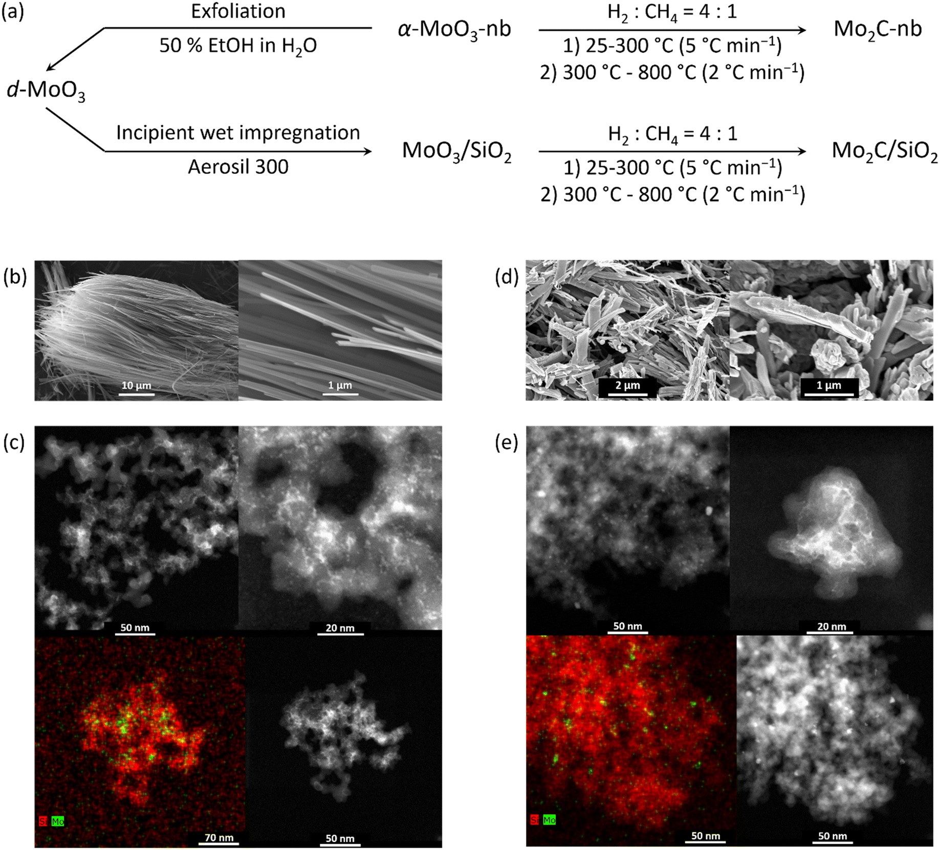 | ||
| Fig. 1 a) Synthesis of Mo2C-nb from α-MoO3-nb and Mo2C/SiO2 from silica-supported delaminated MoO3 films MoO3/SiO2; b) SEM images of as synthesized α-MoO3-nb; c) HAADF-STEM images and EDX elemental (Si and Mo) maps of MoO3/SiO2; d) SEM images of Mo2C-nb; and e) HAADF-STEM images and EDX maps of Mo2C/SiO2. | ||
Characterization
Ex situ X-ray powder diffraction (XRD) data were collected using a PANalytical Empyrean X-ray diffractometer equipped with a Bragg–Brentano HD mirror and operated at 45 kV and 40 mA using CuKα radiation (λ = 1.5418 Å). The materials were examined within the 2θ range of 5–90° using a step size of 0.0167°. The scan time per step was 1 s. Thermogravimetric analysis (TGA) experiments were performed in a Mettler Toledo TGA/DSC 3 instrument. Typically, 750 μL of a colloidal solution of d-MoO3 was placed in a sapphire crucible (900 μL) that was heated to 80 °C (5 °C min−1) and kept for 1 h. Scanning electron microscopy (SEM) was performed on a Zeiss LEO Gemini 1530 microscope. All electron microscopy images were taken at an acceleration voltage of 5 kV. Prior to imaging the materials were coated with a ca. 2 nm conductive layer of platinum.Transmission electron microscopy (TEM) was performed with a double CS corrected JEOL JEM-ARM 300 kV TEM/STEM microscope equipped with two energy-dispersive X-ray spectroscopy (EDX) detectors with a total solid angle of 1.6 sr. The samples for TEM analysis were prepared by embedding nanobelts in the microscopy resin, sandwiched between two dummy silicon wafers, followed by tripod mechanical polishing and gentle Ar ion milling with a GATAN Precision Ion Polishing System (PIPS II) down to electron transparency. Most images were post-processed using HREM-Filters Pro, a commercially available plug-in for Digital Micrograph Package by applying Wiener filter, to reduce noise and background contributions.
In situ XAS experiments were performed at the Swiss-Norwegian Beamlines (SNBL, BM31) at the European Synchrotron Radiation Facility (ESRF, Grenoble, France). XAS spectra were collected at the Mo K-edge using a double-crystal Si (111) monochromator with continuous scanning in transmission mode. The in situ carburization followed by dry reforming of methane (DRM) experiment was performed in a quartz capillary reactor.11,17,25 Energy calibration of the XAS data was based on Mo foil, set at 20000.0 eV. XAS spectra were collected in the range of 19800.0–20800.0 eV, with a total acquisition time of 60 s and a step of 1 eV. In the in situ XAS experiments, ca. 2 mg of the sample was placed between two quartz wool plugs in the capillary reactor (outer diameter 1.5 mm, wall thickness 0.1 mm). The carburization step was performed in a mixture of H2:CH4 = 4:1 in the temperature range from 50 to 750 °C (5 mL min−1, ca. 9 °C min−1 at 50–400 °C and 2 °C min−1 at 400–750 °C) at atmospheric pressure. DRM tests were performed at 8 bar (CH4:CO2 He = 4:3:3) at 730 °C with the total flow rate varying in the range 1.75–3.5 mL min−1. All the flow rates are express at standard conditions of temperature and pressure. Catalyst weight/volume flow rate (W/F, in ms gMo mL−1) are reported in the text below based on the nominal Mo loading. After the DRM reaction, the spent catalysts were exposed to a pure stream of CO2 or CH4 (5 mL min−1, 730 °C). The composition of the outlet gases was monitored online by a mass spectrometer (MS). Ex situ XAS data were collected on pellets of reference materials (MoO2, α-MoO3 and Mo2C) with an optimized amount of sample mixed with cellulose. As-carburized Mo2C was handled in a N2-filled glove box to prepare specimen for XAS analysis in air-tight sealed Al bag. XAS data were processed using the Athena software (Demeter 0.9.25 software package).26 The extracted extended X-ray absorption fine structure (EXAFS) data were k3-weighted and the Fourier transform performed in the k-range 3–10 Å−1 for data collected during thermal treatment and 3–12 Å−1 for that collected at room temperature. The in situ time resolved normalized X-ray absorption near edge structure (XANES) data were analyzed using a MCR-ALS method.27 MCR-ALS analysis was performed with a MATLAB software package using the multivariate curve resolution toolbox.28 Non-negative constraints were applied for both the phase concentration and spectra profiles. The MCR-ALS analysis was complemented with principal component analysis (PCA).
Catalytic testing
The laboratory DRM tests were carried out in a fixed-bed reactor (Hastelloy X, 8 mm inner diameter) at 8 bar. In a typical experiment, 75 mg of the pre-catalyst (α-MoO3-nb or MoO3/SiO2) was placed in between two quartz wool plugs. Prior to the catalytic tests, the pre-catalyst was transformed in situ into Mo2C/SiO2 or Mo2C-nb by thermal treatment in a mixture of H2:CH4 = 4:1 in the temperature range from RT to 800 °C (50 mL min−1, 10 °C min−1 at 25–300 °C and 2 °C min−1 at 300–800 °C) at atmospheric pressure. After this pretreatment, the pressure was increased to 8 bar (N2) and the DRM feed was introduced (CH4:CO2:N2 = 4:3:3, a total flow rate was 10 mL min−1, 800 °C, 8 bar). This gives W/F ca. 5 ms gMo mL−1 for Mo2C/SiO2 and W/F ca. 300 ms gMo mL−1 for Mo2C-nb. The composition of the off-gas was analyzed via a gas chromatograph (GC, PerkinElmer Clarus 580) equipped with a thermal conductivity detector (TCD). N2 was used as an internal standard and all the outlet flow rates were calculated using following equation: | (4) |
Results and discussion
Catalyst preparation and characterization
Scanning electron microscopy (SEM) analysis of α-MoO3-nb confirmed a nanobelt morphology in this material. The length of the nanobelts was typically >100 μm, their width was in the range of 200 to 400 nm and their average thickness ca. 50 nm (Fig. 1b). To prepare delaminated d-MoO3 nanosheets, α-MoO3-nb were ground and sonicated in 50% aqueous ethanol. After centrifugation, the supernatant solution contained well-dispersed MoO3 nanosheets according to TEM (Fig. S1†). Using thermogravimetric analysis, the concentration of d-MoO3 in the colloidal solution was determined as ca. 1.5 mg mL−1. MoO3/SiO2, a material with a nominal loading of 1.75 wt% MoO3, was obtained by incipient wetness impregnation of the d-MoO3 colloidal solution onto a SiO2 support (Aerosil 300). High angle annular dark field scanning transmission electron microscopy (HAADF-STEM) imaging of MoO3/SiO2 revealed a relatively homogeneous distribution of Mo (light contrast) on SiO2 (dark contrast, Fig. 1c). The Mo-rich phase consisted of small agglomerates ca. 5 nm in size. We have reported previously that impregnation of MoO3 nanosheets (contained in the colloidal solution) onto carbon spheres gives agglomerates of MoO3 (mostly amorphous by TEM),11 which are however notably larger, i.e. tens of nanometers, than agglomerates of MoO3 on SiO2 observed in this work.Carburization of α-MoO3-nb in a mixture of CH4 and H2 (H2:CH4 = 4:1) yielded Mo2C-nb. SEM analysis of the carburized (and passivated) material revealed that the carburization process does not affect notably the nanobelt morphology (Fig. 1d). XRD analysis of Mo2C-nb revealed the presence of a single-phase that was assigned to β-Mo2C, consistent with the complete carburization of α-MoO3-nb (Fig. S2†). Similarly, the carburization of MoO3/SiO2 led to Mo2C/SiO2 (vide infra). STEM imaging of Mo2C/SiO2, (after exposure of the specimen to air during sample transfer) revealed the formation of particles of ca. 5–10 nm in diameter (Fig. 1e).
Catalytic performance
We evaluated and compared the DRM activity of Mo2C-nb and Mo2C/SiO2 at 800 °C and 8 bar pressure in the laboratory-scale reactor. Mo2C-nb catalyst shows a stable performance in a CH4-rich flow (i.e. CH4:CO2:N2 = 4:2:4) and a W/F ratio of 300 ms gMo mL−1. A methane conversion of ca. 60% under these conditions suggests that methane decomposition (eqn (2)) takes place, in line with the observations of formation of coke via TEM analysis (vide infra). Additionally, the obtained H2:CO ratio of ca. 0.9 indicates that the reverse water gas shift (RWGS), methane decomposition and DRM reactions compete under these conditions. We also observe that the catalyst deactivated with decreasing W/F (W/F = 150 ms gMo mL−1) or when decreasing the CH4:CO2 ratio (i.e. CH4:CO2:N2 = 4:3:3; methane conversion of ca. 10%, Fig. S3†). XRD analysis of the deactivated catalyst (after 20 h TOS, Fig. S3†) revealed formation of MoO2, although β-Mo2C was still present in the used catalyst (Fig. S4†).
Mo2C/SiO2 shows a stable catalytic performance over 8 h of time on stream (TOS) under a CH4-rich flow (CH4:CO2:N2 = 4:3:3; W/F = 5.25 ms gMo mL−1), with a methane conversion of ca. 55% (Fig. S5†). However, similarly to Mo2C-nb, the obtained H2:CO ratio of ca. 0.7 indicates that the RWGS and DRM reactions compete under these conditions.
In situ XAS under carburization conditions
To gain insight into the carburization pathways and to assess the structure and the chemical state of the activated Mo phase, we followed the transformation of α-MoO3-nb to Mo2C-nb by in situ Mo K-edge XAS using a capillary cell reactor. Based on the linear dependence of the oxidation state of Mo and the edge position of Mo in K-edge XANES spectra,29–31 a calibration curve (based on the Mo K-edge positions of Mo, MoO2 and MoO3 references) was used to determine the oxidation state of Mo in analyzed samples (Fig. S6†). The XANES spectrum of α-MoO3-nb has identical features to the reference spectrum of α-MoO3, with a distinct pre-edge feature at 20006.5 eV, three well-defined white line features (at ca. 20026.8, 20038.7 and 20054.3 eV) and the edge position at 20016.4 eV, i.e. in line with an oxidation state of Mo6+.29 Likewise, EXAFS analysis agrees with an α-MoO3 local environment (Fig. S10†). The in situ XANES spectra collected during the carburization treatment showed only minor changes up to 500 °C with a slight shift of the Mo K-edge energy position to 20015.5 eV at 500 °C (Fig. 2a and S7†). This shift to lower energies indicates a partial reduction of Mo, likely taking place at the surface-to-subsurface layers. The first major change occurred at ca. 525 °C and is manifested in the disappearance of the pre-edge feature at 20006.5 eV and a shift of the absorption edge to 20011.5 eV (Mo oxidation state of +4), indicating a reduction of α-MoO3-nb to MoO2, (see also MoO2 reference XANES spectrum in Fig. S8†). A second transition took place at ca. 555 °C and is associated with a sudden shift of the Mo K-edge energy from 20011.5 eV to 20000.2 eV, indicating a rapid reduction of MoO2 to Mo2C. No further changes were observed above 750 °C and the XANES spectrum of the final phase matches the reference spectrum of β-Mo2C, confirming the complete carburization of α-MoO3-nb to Mo2C-nb under the conditions applied here. The evolution of the EXAFS data agrees with the changes observed by XANES (Fig. S9†).
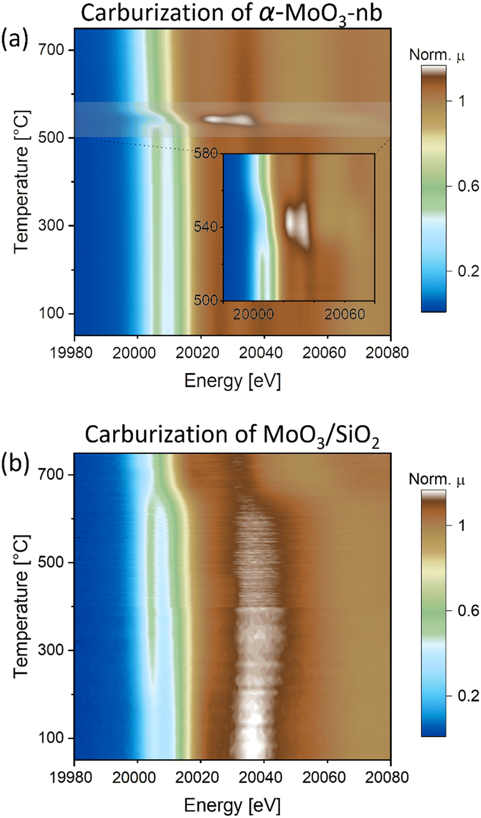 | ||
| Fig. 2
In situ Mo K-edge XANES (contour plots of the intensity as a function of energy and time) during carburization of a) α-MoO3-nb and b) MoO3/SiO2 under H2:CH4 = 4:1 gas mixture. | ||
The XANES spectrum of MoO3/SiO2 showed a similar pre-edge feature (at ca. 20006.5 eV) and edge energy position (at 20016.4 eV) as the reference spectrum α-MoO3, however it exhibited different white line features, notably with only one well-defined peak at 20037.5 eV. We hypothesize that the different white line peaks are linked to the dispersion of MoO3 nanosheets onto SiO2,32 leading to a different local structure around Mo (Fig. 2b and S7†). In line with this hypothesis, the EXAFS analysis of MoO3/SiO2 showed a different local structure when compared to that of α-MoO3-nb, showing a significantly lower magnitude of the second coordination sphere pointing to a lower Mo–Mo coordination which can be linked to the high dispersion over SiO2 (Fig. S10 and Table S1†).
Interestingly, two notable changes are observed in the in situ XANES spectra: one at a low temperature between 200 and 250 °C, and one at a higher temperature at ca. 650 °C. The low temperature transition is associated with the loss of the initially more well-defined feature around 20037.5 eV with broadening of the white line and a more intense pre-edge feature that is also shifted to lower energies, ca. 20006.2 eV (Fig. 2b and S7†). Noteworthy, the intensity of the pre-edge feature increases. The XANES spectrum of this intermediate phase does not correspond to the reference spectrum of MoO2 and neither is it similar to the previously reported spectra of bulk Mo oxides.31,33 However, it resembles the Mo K-edge spectra of isolated Mo-oxo species (Mo oxidation state between +5 and +6) on zeolites supports (i.e. ZSM-5 and H-SSZ-13).34–36 Based on this observation, we propose that the MoO3 phase in MoO3/SiO2 forms small oxo clusters and/or highly dispersed Mo oxo sites on the SiO2 surface when the temperature reaches 200–250 °C. This is in line with the EXAFS data indicating a sudden change in the second coordination sphere at ca. 200 °C (Fig. S11†). The high temperature transition is associated with the disappearance of the well-defined pre-edge feature and a shift of the Mo K-edge energy from 20015.4 eV to ca. 20000.0 eV, indicating the reduction and carburization of Mo. The XANES spectrum at 750 °C corresponds to the reference spectrum of β-Mo2C, confirming the complete carburization of MoO3/SiO2 to Mo2C/SiO2. Quantification of the phase evolution will be discussed based on MCR-ALS analysis of the XANES data (vide infra).
In situ XAS under DRM conditions
Next, we investigated the catalysts' structure and chemical state under DRM conditions (CH4:CO2 = 4:3; at 8 bar and 730 °C) while the off-gas was analyzed by MS. Under DRM conditions, the in situ XANES spectra of the Mo2C-nb catalyst (W/F = 45 ms gMo mL−1) revealed an almost immediate shift of the Mo K-edge energy from 20000.2 eV to 20011.6 eV indicating a rapid oxidation of carbidic Mo sites in Mo2C to a Mo4+ state (Fig. 3a). At the same time, a notable increase in the MS signal of H2O was detected, indicating the presence of the competing RWGS reaction. A similar behavior under DRM conditions has been reported previously for a Mo2C/C catalyst, i.e., the oxidation of Mo to an oxycarbide phase has been correlated to the onset of the RWGS reaction.11 No further significant changes were observed for the Mo2C-nb catalyst between TOS 10 min and 120 min (Fig. 3a and S12†). Next, we exposed the deactivated Mo2C-nb catalyst to a stream of pure CH4 to determine if it can be regenerated. However, no changes in the XANES spectra were observed throughout the 60 min exposure of the catalyst to CH4, indicating the irreversibility of catalyst oxidation (in these conditions).
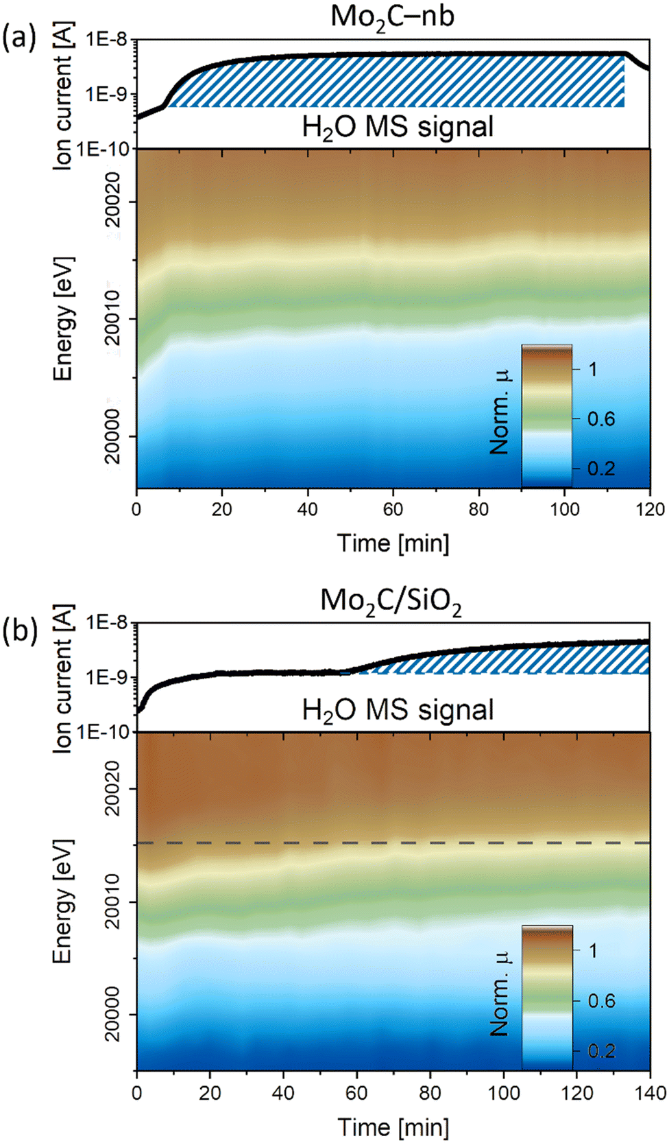 | ||
| Fig. 3 In situ Mo K-edge XANES (contour plots of the intensity as a function of energy and time) during DRM (capillary reactor, 730 °C, 8 bar) of a) Mo2C-nb (W/F = 45 ms gMo mL−1) and b) Mo2C/SiO2 (W/F = 0.8 ms gMo mL−1), complemented by the evolution of H2O MS signal. | ||
The XANES changes during DRM of Mo2C/SiO2 were also evaluated (W/F = 0.8 ms gMo mL−1). In contrast to the rapid oxidation of Mo2C-nb, a slower Mo oxidation was observed for Mo2C/SiO2, identified by a gradual shift of the Mo K-edge to higher energies (Fig. 3b). The slower oxidation rate is consistent with the higher stability of Mo2C/SiO2 under DRM conditions. After ca. 60 min TOS, a pre-edge feature appears in the XANES spectra of this catalyst. Interestingly, consistent with the evolution of the XANES data, the MS data reveals an increase of the H2O signal starting from TOS = 60 min. Therefore, this indicates that the onset of the RWGS reaction coincides with a phase transformation of the catalyst (for the nature and quantitative analysis of the oxidized species vide infra MCR-ALS analysis).11 Additional exposure of the catalyst to a stream of pure CO2 shifts the Mo K-edge to higher energies, indicating a further oxidation of the material (Fig. S13†). Additionally, the intensity of the pre-edge feature increases significantly and the XANES spectrum at the end of the reaction corresponds clearly to the intermediate phase observed during carburization. Interestingly, contrary to the deactivated Mo2C-nb catalyst, an oxidized Mo2C/SiO2 can be partially reduced (and likely, recarburized) under a pure stream of CH4 (Fig. S13†). This observation indicates that a dynamic oxidation-recarburization process may in principle take place under DRM conditions,7 yet it has been reported that addition of transition metals such as Ni is required to increase the rate of recarburization, in order to match the oxidation rate.12,13
Phase evolution by MCR-ALS analysis of in situ XAS data
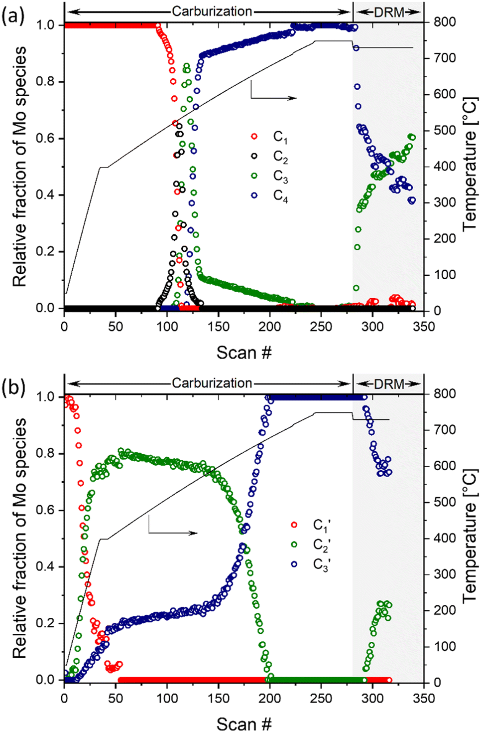
A quantitative analysis of the in situ XANES data was performed via the MCR-ALS method combined with principal component analysis. This method allowed us to assess the phase evolution during carburization and DRM, as well as to extract the main components that describe the dynamics of the investigated materials. The analysis of the Mo2C-nb system revealed that the carburization and DRM processes could be fully described using four distinct components (Fig. S14†). Those four spectra (C1, C2, C3 and C4), extracted using MCR-ALS analysis, are presented in Fig. S15.† To assign the extracted components, we compare them with available references spectra. Component C1 is identical to that of α-MoO3 and the spectrum of component C4 is identical to that of β-Mo2C. Component C2 possess a well-defined pre-edge at ca. 20007.1 eV, albeit of a lower intensity as compared to C1. The Mo K-edge position in C2 was determined as 20015.8 eV revealing an estimated Mo oxidation state between +5 and +6. Based on this oxidation state and the resemblance of the spectrum to that of Mo4O11,33 we ascribe the C2 component to Mo4O11 or to a mixture of different MoOx (e.g. Mo4O11, Mo8O23, Mo17O47, etc.) species. Lastly, the Mo K-edge position (20011.9 eV) and the XANES features of component C3 resembles strongly that of MoO2, which allows us to ascribe C3 to MoO2. The changes of the fractions of components C1–C4 with increasing carburization temperature are presented in Fig. 4a. The MCR analysis indicates that C1 (MoO3) is stable up to ca. 495 °C and from 495 °C this component starts to transform rapidly to C2 followed by C3; it disappears completely at ca. 535 °C. The C2 component was found to be very short-lived, reaching its maximum fraction of 0.64 at 530 °C while completely disappearing already at 565 °C and being replaced by a mixture of C3 and C4. The C3 component (assigned to MoO2) appears at ca. 525 °C and quickly reaches its maximum fraction of 0.85 at 545 °C. Subsequently, the concentration of C3 decreases rapidly being replaced by C4 (Mo2C, which appears at 545 °C) and drops down to a fraction ca. 0.1 at 570 °C. Increasing the temperature further, yield a further decrease of the fraction of MoO2 until it disappears completely at ca. 710 °C (Fig. 4a). This observation can be explained by the slow carburization of the core of the nanobelts.
 | ||
| Fig. 4 Phase evolution of a) α-MoO3-nb and b) MoO3/SiO2 during the carburization process and DRM according to MCR-ALS of the XANES data. | ||
Turning to the Mo2C/SiO2 catalyst, only three distinct components are involved in the carburization process (Fig. S16†). Those three spectra (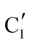 ,
,  and
and  ) extracted using MCR-ALS analysis are presented in Fig. S17.† Component
  is assigned to the initial MoO3 phase dispersed onto SiO2 (vide supra). The intermediate
  component shows a unique white line shape which resembles the Mo K-edge spectra of previously reported molybdenum single sites (MOx/SiO2).34–36 The edge energy (20015.4 eV) indicates Mo in an oxidation state between +5 and +6. Component
  shows similar features to that of the β-Mo2C reference and thus is assigned to the carburized Mo (Mo2C) supported on SiO2. Fig. 4b plots the changes of the fraction of the
  ,
,  and
and  components during the carburization process. The intermediate
  component starts to appear at ca. 120 °C and reaches its maximum level of ca. 0.8 at 400 °C. The fraction of the component
  , corresponding to the initial state of the material, reduces rapidly until it disappears at ca. 425 °C. Interestingly, the MCR analysis indicates that the molybdenum carbide phase (
 ) appears already at ca. 200 °C and reaches a fraction of ca. 0.2 at 425 °C during the initial stage of carburization. The concentration of
  starts to increase slowly replacing
  until it reaches a weight fraction of 0.3 at ca. 600 °C. Afterwards, a rapid carburization of
  to
to  occurs yielding a pure
  phase at ca. 680 °C (Fig. 4b).
The MCR analysis indicates that the changes in the XANES spectra under DRM conditions can be described with the same components that have been identified in the carburization process (Fig. 4a and b). In particular, for Mo2C-nb the evolution of the in situ XANES data during DRM conditions can be fully described with the components MoO2 (C3) and Mo2C (C4). The MCR analysis indicates that under DRM conditions Mo2C is rapidly oxidized to MoO2 yielding a fraction of MoO2 of >0.6 after 120 min TOS (Fig. 4a).
The evolution of the in situ XANES spectra of Mo2C/SiO2 during DRM can be fully described by the components  and
and  (Mo2C) (Fig. 4b). However, the MCR analysis indicates no changes in the phase composition during 45 min TOS revealing that only
  (Mo2C) is present until up to 45 min under DRM conditions. Subsequently, a slow oxidation of Mo2C into
  (MOx/SiO2) is revealed, reaching asymptotic fractions of 0.75 for Mo2C and 0.25 for
  after ca. 120 min TOS (Fig. 4b). To summarize, our studies reveal that the degree of oxidation of the carbidic phase in Mo2C/SiO2 is lower than for Mo2C-nb under DRM conditions. It should be highlighted that although in the in situ XANES setup requires a different W/F ratio as compared to the laboratory reactor system (i.e. parameters of the synchrotron experimental setup yield a ca. one order of magnitude lower W/F ratio as compared to the laboratory reactor), and this can affect the degree of catalysts oxidation, both laboratory reactor and synchrotron capillary experiments provide qualitatively similar results. The observed MoO2 phase via ex situ XRD analysis of the spent catalyst (Fig. S4†) correlates well with the in situ XANES analysis.
It has been previously reported that the carburization of MoO3/C to Mo2C/C and the evolution of Mo2C/C under DRM conditions involves an oxycarbide intermediate.11 In contrast, we do not observe oxycarbide intermediates in the current study, despite similar experimental conditions and the same starting Mo precursor (d-MoO3). This may be explained by the support effect, that is, the carbon support in MoO3/C and Mo2C/C enables carburization and DRM pathways that involve a Mo2CxOy intermediate that seems to be hindered for Mo2C-nb and Mo2C/SiO2 of this work. That being said, we cannot exclude the formation of surface oxycarbides that can bring about the RWGS reactivity of in situ oxidized Mo2C-nb and Mo2C/SiO2.
Morphology of the used catalyst
Lastly, the morphology of the reacted Mo2C-nb catalyst (after 20 h TOS, Fig. S3,† followed by passivation) was investigated using SEM and TEM. The SEM analysis revealed that while Mo2C-nbreacted has preserved its nanobelt morphology, the initially smooth nanobelt surface is found to be decorated by small particles (Fig. S18†). To determine the nature of the observed particles Mo2C-nbreacted was analyzed further using TEM. A cross-section of Mo2C-nbreacted reveals that it is porous, i.e., every nanobelt consists of ca. 10–20 nm particles (Fig. S19†). This observation can be possibly explained by the significantly lower molar volume of Mo2C compared to MoO3 (i.e. Vm(MoO3) = 30.6 cm3 mol−1, Vm(MoO2) = 19.8 cm3 mol−1, 1/2Vm(Mo2C) = 11.5 cm3 mol−1) leading to the formation of voids during the carburization process. High resolution TEM imaging reveals that particles are often covered with graphitic and/or amorphous carbon (Fig. S20†), indicating methane decomposition (eqn (2)) during DRM that results in coke deposition. Since the catalyst deactivation test presented in Fig. S3† uses two ratios of CH4:CO2, i.e. an initial 2:1 ratio is followed by a 4:3 ratio, coking likely proceeds in the CH4-rich feed while the catalyst oxidation (from Mo2C to MoO2) likely proceeds in the CO2-rich feed; both processes lead to the catalyst deactivation (Fig. S3†). Analysis of the lattice fringes of the particles coated by coke shows that these particles are composed of Mo2C.
Conclusions
In situ Mo K-edge XAS uncovered that unsupported MoO3 nanobelts and MoO3/SiO2 undergo different carburization pathways (using a 1:4 mixture of CH4:H2) to form, respectively, Mo2C and Mo2C/SiO2. The carburization of α-MoO3-nb proceeds via MoO2, and that of MoO3/SiO2via the formation of highly dispersed MoOx species. Catalytic tests show that both carburized materials provide a stable performance in the DRM reaction at an elevated pressure of 8 bar and a CH4-rich flow (i.e. CH4:CO2:N2 = 4:2:4). In particular, unsupported Mo2C-nb shows a stable performance at high W/F = 300 ms gMo mL−1, but deactivates when decreasing W/F (to 150 ms gMo mL−1) or when increasing the CO2 concentration. The dispersion of Mo2C onto SiO2 increases significantly the stability of the catalyst under DRM conditions. In particular, Mo2C/SiO2 exhibits a high stability over 8 h TOS at W/F = 5.25 ms gMo mL−1. In situ XAS showed that under DRM conditions Mo2C oxidizes to MoO2 leading to catalytic deactivation. The degree of oxidation is different between Mo2C-nb and Mo2C/SiO2, whereby Mo2C/SiO2 is more resistant towards oxidation under DRM conditions, i.e. ca. 75% of Mo2C remained in Mo2C/SiO2 and the rest is MOx/SiO2 (without MoO2 formation) after 120 min TOS as compared to only 40% of Mo2C for Mo2C-nb. In situ XAS experiments show a clear correlation between the increased activity in the undesired competing reverse water gas shift reaction and the oxidation of carbidic Mo in Mo2C-nb and Mo2C/SiO2 under DRM conditions.
Author contributions
This article was prepared and written through contribution of all the authors. All authors have read and agreed to the final version of the manuscript.Conflicts of interest
The authors declare that there is no conflict of interest regarding the publication of this article.Acknowledgements
This publication was created as part of NCCR Catalysis (Grant Number 180544), a National Centre of Competence in Research funded by the Swiss National Science Foundation. We acknowledge funding from the European Research Council (ERC) under the European Union‘s Horizon 2020 research and innovation program (grant agreement No. 819573), and from ETH Zürich (ETH-40 19-2). The Swiss Norwegian beamlines (SNBL at ESRF) facility is acknowledged for provision of beamtime. The authors thank ScopeM for the use of their electron microscopy facilities. Dr. Elena Willinger is thanked for her assistance with the TEM data analysis of the spent Mo2C-nb catalyst.References
- M. S. Fan, A. Z. Abdullah and S. Bhatia, ChemCatChem, 2009, 1, 192–208 CrossRef CAS.
- D. Pakhare and J. Spivey, Chem. Soc. Rev., 2014, 43, 7813–7837 RSC.
- L. C. Buelens, V. V. Galvita, H. Poelman, C. Detavernier and G. B. Marin, Science, 2016, 354, 449–452 CrossRef CAS PubMed.
- S. M. Kim, P. M. Abdala, T. Margossian, D. Hosseini, L. Foppa, A. Armutlulu, W. van Beek, A. Comas-Vives, C. Coperet and C. Muller, J. Am. Chem. Soc., 2017, 139, 1937–1949 CrossRef CAS PubMed.
- Z. Bian and S. Kawi, J. CO2 Util., 2017, 18, 345–352 CrossRef CAS.
- M. A. Naeem, P. M. Abdala, A. Armutlulu, S. M. Kim, A. Fedorov and C. R. Müller, ACS Catal., 2020, 10, 1923–1937 CrossRef CAS.
- J. B. Claridge, A. P. E. York, A. J. Brungs, C. Marquez-Alvarez, J. Sloan, S. C. Tsang and M. L. H. Green, J. Catal., 1998, 180, 85–100 CrossRef CAS.
- Z. Lin, S. R. Denny and J. G. Chen, J. Catal., 2021, 404, 929–942 CrossRef CAS.
- A. J. Brungs, A. P. E. York, J. B. Claridge, C. Marquez-Alvarez and M. L. H. Green, Catal. Lett., 2000, 70, 117–122 CrossRef CAS.
- D. C. LaMont and W. J. Thomson, Chem. Eng. Sci., 2005, 60, 3553–3559 CrossRef CAS.
- A. Kurlov, X. Huang, E. B. Deeva, P. M. Abdala, A. Fedorov and C. R. Müller, Nanoscale, 2020, 12, 13086–13094 RSC.
- C. G. Silva, F. B. Passos and V. d. S. T. da Silva, J. Catal., 2019, 375, 507–518 CrossRef CAS.
- R. D. Barbosa, M. A. S. Baldanza, N. S. de Resende, F. B. Passos and V. L. d. S. T. da Silva, Catal. Lett., 2020, 151, 1578–1591 CrossRef.
- P. Da Costa, J.-L. Lemberton, C. Potvin, J.-M. Manoli, G. Perot, M. Breysse and G. Djega-Mariadassou, Catal. Today, 2001, 65, 195–200 CrossRef CAS.
- A. Mehdad, R. E. Jentoft and F. C. Jentoft, J. Catal., 2017, 347, 89–101 CrossRef CAS.
- D. C. LaMont, A. J. Gilligan, A. R. S. Darujati, A. S. Chellappa and W. J. Thomson, Appl. Catal., A, 2003, 255, 239–253 CrossRef CAS.
- A. Kurlov, E. B. Deeva, P. M. Abdala, D. Lebedev, A. Tsoukalou, A. Comas-Vives, A. Fedorov and C. R. Müller, Nat. Commun., 2020, 11, 4920 CrossRef CAS PubMed.
- H. Gao, Z. Yao, Y. Shi and S. Wang, Catal. Sci. Technol., 2018, 8, 697–701 RSC.
- A. R. S. Darujati and W. J. Thomson, Appl. Catal., A, 2005, 296, 139–147 CrossRef CAS.
- C. Shi, A. Zhang, X. Li, S. Zhang, A. Zhu, Y. Ma and C. Au, Appl. Catal., A, 2012, 431-432, 164–170 CrossRef CAS.
- T. Mo, J. Xu, Y. Yang and Y. Li, Catal. Today, 2016, 261, 101–115 CrossRef CAS.
- M. M. Sullivan, C.-J. Chen and A. Bhan, Catal. Sci. Technol., 2016, 6, 602–616 RSC.
- A. Chithambararaj, N. Rajeswari Yogamalar and A. C. Bose, Cryst. Growth Des., 2016, 16, 1984–1995 CrossRef CAS.
- F. Ji, X. Ren, X. Zheng, Y. Liu, L. Pang, J. Jiang and S. Liu, Nanoscale, 2016, 8, 8696–8703 RSC.
- W. van Beek, O. V. Safonova, G. Wiker and H. Emerich, Phase Transitions, 2011, 84, 726–732 CrossRef CAS.
- B. Ravel and M. Newville, J. Synchrotron Radiat., 2005, 12, 537–541 CrossRef CAS PubMed.
- A. Tsoukalou, P. M. Abdala, D. Stoian, X. Huang, M. G. Willinger, A. Fedorov and C. R. Muller, J. Am. Chem. Soc., 2019, 141, 13497–13505 CrossRef CAS PubMed.
- J. Jaumot, A. de Juan and R. Tauler, Chemom. Intell. Lab. Syst., 2015, 140, 1–12 CrossRef CAS.
- S. P. Cramer, T. K. Eccles, F. W. Kutzler, K. O. Hodgson and L. E. Mortenson, J. Am. Chem. Soc., 1976, 98, 1287–1288 CrossRef CAS PubMed.
- T. Ressler, J. Wienold, R. E. Jentoft and T. Neisius, J. Catal., 2002, 210, 67–83 CrossRef CAS.
- E. B. Deeva, A. Kurlov, P. M. Abdala, D. Lebedev, S. M. Kim, C. P. Gordon, A. Tsoukalou, A. Fedorov and C. R. Müller, Chem. Mater., 2019, 31, 4505–4513 CrossRef CAS.
- Z. Huang, W. Bensch, W. Sigle, P. A. van Aken, L. Kienle, T. Vitoya, H. Modrow and T. Ressler, J. Mater. Sci., 2007, 43, 244–253 CrossRef.
- T. Ressler, R. E. Jentoft, J. Wienold, M. M. Günter and O. Timpe, J. Phys. Chem. B, 2000, 104, 6360–6370 CrossRef CAS.
- I. Lezcano-Gonzalez, R. Oord, M. Rovezzi, P. Glatzel, S. W. Botchway, B. M. Weckhuysen and A. M. Beale, Angew. Chem., Int. Ed., 2016, 55, 5215–5219 CrossRef CAS PubMed.
- N. Kosinov, E. A. Uslamin, L. Meng, A. Parastaev, Y. Liu and E. J. M. Hensen, Angew. Chem., Int. Ed., 2019, 58, 7068–7072 CrossRef CAS PubMed.
- M. Agote-Aran, A. B. Kroner, D. S. Wragg, W. A. Slawinski, M. Briceno, H. U. Islam, I. V. Sazanovich, M. E. Rivas, A. W. J. Smith, P. Collier, I. Lezcano-Gonzalez and A. M. Beale, Molecules, 2020, 25, 5048 CrossRef CAS PubMed.
Footnotes |
| † Electronic supplementary information (ESI) available. See DOI: https://doi.org/10.1039/d2cy00729k |
| ‡ Current address: Laboratory for Bioenergy and Catalysis, Paul Scherrer Institute (PSI), 5232 Villigen PSI, Switzerland. |
| § Current address: Department of Chemistry, Technical University Munich, Lichtenbergstrasse 4, 85748 Garching, Munich, Germany. |
| This journal is © The Royal Society of Chemistry 2022 |