Advanced cathodic free-standing interlayers for lithium–sulfur batteries: understanding, fabrication, and modification
Jianhua
Zhou
,
Ting
Wu
,
Xin
Zhou
and
Jingyu
Xi
 *
*
Institute of Materials Research, Shenzhen International Graduate School, Tsinghua University, Shenzhen, 518055, China. E-mail: xijy@tsinghua.edu.cn
First published on 5th July 2022
Abstract
In the past decades, lithium–sulfur batteries (LSBs) have demonstrated huge practical potential due to their ultrahigh theoretical specific capacity, low price, and environmental friendliness. However, LSBs are still faced with the problems of volumetric expansion, slow reaction kinetics, and short working life due to the shuttling of polysulfides. The introduction of a free-standing interlayer is a good way to solve the problems because of the physical confinement, chemical entrapment, and conversion. This review summarizes the common fabrication methods of free-standing interlayers, including the power-originated and film-originated methods. The modification of the as-prepared free-standing interlayers is also accomplished into physical treatment, atomic doping, and compound introduction. Finally, we conclude and compare the different fabrication methods of free-standing interlayers and their modifications and put forward the outlook of the high-performance free-standing interlayers.
Introduction
Nowadays, with the development of industry and technology, humans still need to consume enormous energy. In 2050, the energy demand is estimated to be three times the amount today.1 Therefore, humans are confronted with an energy crisis. At the same time, the greenhouse gases emitted for decades have caused distinct global warming and brought a series of problems, such as the rise of sea level and frequent extreme weather. Humans are also trapped in the climate crisis; thus, many countries have launched their net-zero emission plans. Fortunately, the new energy from wind and biomass energy can tackle both crises, which rely on the device of energy storage. In recent years, electrochemical energy storage has become the second largest energy storage mode after pumped energy storage, which is mostly made up of rechargeable batteries.2 The commonly used and investigated batteries include lead-acid batteries, lithium-ion batteries (LIBs), sodium-ion batteries (SIBs), sodium–sulfur batteries (SSBs), and lithium–sulfur batteries (LSBs). Among all kinds of batteries, LSBs stand out due to their ultrahigh theoretical specific capacity (1675 mA h g−1), low price, and environmental friendliness.As shown in Fig. 1a, the development of LSBs has experienced a long and hard time. The earliest research concerning LSBs dates from the 1940s.3 In the 1960s, the concept of S cathode and the prototype of LSBs were both first introduced in succession.4,5 In 1976, Whittingham et al. studied the usage of a lithium metal anode, which was a pioneering job and still provides good reference research even now.6 In the 1980s, Peled et al. made a pioneering investigation on the liquid dioxolane-based electrolyte, which is still the regular electrolyte of LSBs currently.7 In 2004, Mikhaylik et al. quantitatively studied the shuttling of polysulfides of LSBs and gave theoretical models of typical behaviors such as self-discharge and discharge/charge efficiency.8 In 2009, Nazar et al. made an outstanding breakthrough by burying sulfur into mesoporous CMK-3 by heating at 155 °C, enabling LSBs with a high initial capacity of 1320 mA h g−1 due to the confinement effect.9 In 2012, Manthiram et al. introduced a free-standing porous multiwalled carbon nanotube paper as an interlayer to effectively improve the Coulombic efficiency and specific capacity at a low cost, starting the research on various interlayers.10 In 2014, Sion Power Incorporation powered a high-altitude pseudo-satellites aircraft using LSBs, which provided 350 W h kg−1, the highest available for a rechargeable battery, demonstrating the superiority and prospect of LSBs.11 However, the cycle life of LSBs still cannot meet the commercial demand.
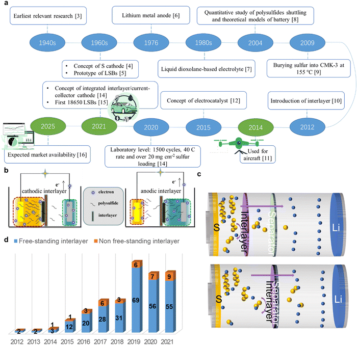 | ||
| Fig. 1 (a) A brief development history of LSBs. (b) Schematic of LSBs with cathodic interlayer and anodic interlayer. Reproduced from ref. 12 with permission from the American Chemical Society, copyright 2017. (c) Schematic of LSBs with free-standing interlayers (up) and non-free-standing interlayers (down). (d) Bar chart of the publication number of free-standing and non-free-standing interlayers for LSBs since 2012. Data from the Web of Science using the keywords “lithium or Li”, “sulfur or sulphur or S” and “batter* or cell* or chemistry” with the title containing “interlayer”. | ||
More investigations into the fundamentals and more practical attempts need to be conducted effectively. In 2015, for the first time, Ganguli et al. proposed the concept of the electrocatalyst, boosting the development of catalysts in LSBs.13 Later, Xi et al. combined the interlayer, current collector, and cathode, and put forward the concept of the integrated interlayer/current-collector cathode.14 Now the performance of LSBs at the laboratory level can reach a life of 1500 cycles, a rate of 40C and sulfur loading of more than 20 mg cm−2.15 The practical development has come in the form of the world's first 18![[thin space (1/6-em)]](https://www.rsc.org/images/entities/char_2009.gif) 650 LSBs made by the company Lyten, which is expected to start the production and availability in the market in 2025.16,17
650 LSBs made by the company Lyten, which is expected to start the production and availability in the market in 2025.16,17
By reviewing the history of LSBs, it is easy to know that the main problems faced by LSBs on the way to practical applications are as follows. The positive component sulfur has a poor conductivity and suffers an evident volume expansion to form Li2S. The life of LSBs decreases due to the shuttle effect of polysulfides in the reaction process. The dendritic puncture of the lithium anode leads to separator rupture, further causing safety problems. As a low cost and effective method, the introduction of an interlayer plays a great role in inhibiting the shuttle effect, strengthening the conversion between polysulfides and sulfur as well as protecting the separator from being pierced by dendrites. Literally, the interlayers are located between the separator and the cathode (cathodic interlayer) or anode (anodic interlayer), as shown in Fig. 1b.12 Therefore, interlayers with such unique locations naturally hamper the movement of polysulfides between the cathode and the anode. A slight modification in the interlayer, including enhancing the porosity or introducing the functional components, can achieve the effect of physical/chemical adsorption, confinement, and conversion of polysulfides, improving the reactional kinetics and lengthening the working lifespan. The anodic interlayer is used for the uniform deposition of lithium and protects the separator from being pierced by dendrite by lowering the local current and guiding the steady Li+ flux.18 However, the shuttle effect does not get obviously suppressed by anodic interlayers and relevant research has focused more on the area of lithium metal anode instead of LSBs. Thus, this review sets a limit o the cathodic interlayer.
As can be seen from Fig. 1d, in recent years, the investigation of interlayers has reached a considerable quantity. All interlayers can be generally divided into free-standing and non-free-standing. As shown in Fig. 1d, the former is usually a separately inserted structure, while the latter often attaches a functional layer on the separator or the cathode by suction filtration, craping, and so on. Non-free-standing interlayers tend to suffer poor surface uniformity and impede further standardization. Besides, poor adhesion with the substrate causes an unstable structure during the discharge process. Therefore, this study focuses on the review of free-standing interlayers.
Fabrication methods
To obtain a free-standing interlayer for specific requirements and purposes, researchers need to fabricate it in particular. The general process of fabrication consists of two steps: firstly compact independent layer forms, and then small discs are punched using a tablet punching machine (for coin cells). These methods differ in the process of forming the independent layer, which either comes from the powder material or the existent film. The powder-originated fabrication methods mainly include electrospinning, wet spinning, slurry casting, vacuum filtration, soaking drying, and self-assembly methods. The film-originated fabrication can be achieved by high-temperature carbonization, chemical vapor deposition (CVD), and atomic layer deposition (ALD). Table 1 summarizes the parameters of the fabrication method, interlayer material, thickness/weight, sulfur areal loading, and electrochemical performance of different types of interlayers.| Fabrication method | Interlayer material | Thickness (μm)/area mass (mg cm−2) | Sulfur areal loading (mg cm−2) | Initial capacity (mA h g−1) | Residual capacity (mA h g−1) | Capacity decay per cycle (%) | Ref. |
|---|---|---|---|---|---|---|---|
| Electrospinning | Titanium molybdenum nitride-decorated carbon nanofibers | 70/0.255 | 1.1 | 947 | 390 (2C, 1000 cycles) | 0.059 | 19 |
| CoSe@NC nanofibers | 83/— | 1.2–1.5 | 797 | 669.1 (1C, 200 cycles) | 0.161 | 20 | |
| TiO–TiO2 nanoparticle/B–N co-doped CNFs | 18/1.2 | 2.5 | 1014.7 | 680 (0.5C, 400 cycles) | 0.090 | 21 | |
| NiCo2S4-CNFs | 26.73/— | 1.3 | 867 | 604 (1C, 500 cycles) | 0.060 | 22 | |
| CoS2/ACCF | 10/0.07 | 1.8 ± 0.2 | 1050.0 | 580 (1C, 500 cycles) | 0.090 | 23 | |
| ZIF-7@PCF | — | — | 810.0 | 654 (1C, 500 cycles) | 0.030 | 24 | |
| Wet spinning | Nitrogen-doped graphene fiber | 130–150/2.0 | 2.0-5.0 | 658.8 | 605 (0.5C, 200 cycles) | 0.041 | 25 |
| Bi2O3-Polyoxometalate nanowires | 100/— | — | 877.0 | 782 (2C, 850 cycles) | 0.013 | 26 | |
| Vacuum filtration | Graphene oxide/carbon nanotubes | 30/1.1 | 1.0 | 1370 | 671 (0.2C, 300 cycles) | 0.170 | 27 |
| ZnO/CNT/RGO | 0/0.85 | 1.7 | 1061 | 768 (0.2C, 150 cycles) | 0.180 | 28 | |
| Graphene oxide/carbon nanotube | >0.7/— | 1.1 | 1591.6 | 1000 (0.2C, 50 cycles) | 0.740 | 29 | |
| Multiwalled carbon nanotube | 40–50/0.82–1.11 | — | 1446 | 962 (0.2C, 50 cycles) | 0.670 | 10 | |
| C–C–N–Co | 10/0.45 | 1.0 | 770 | 500 (2C, 700 cycles) | 0.058 | 30 | |
| Slurry casting | Ni/SS-PI | 100/10 | 4.2 | 1190.9 | 935.7 (0.5C, 600 cycles) | 0.035 | 31 |
| MoS2/PANI | —/— | 1–1.2 | 1100.0 | 600 (0.2C, 500 cycles) | 0.091 | 32 | |
| CG-CFG@Mo2C | 0.1/— | 1.8 | 1050.0 | 638 (0.5C, 400 cycles) | 0.098 | 33 | |
| TiOX/carbon paper | —/3.0 | 1.5 | 1000.0 | 970 (0.5C, 100 cycles) | 3.000 | 34 | |
| ATTP/CNTs@PAN | 150/2.7 | 1.5 | 1283.0 | 785 (0.2C, 300 cycles) | 0.129 | 35 | |
| SMPC | 170 ± 5/3.7–4.3 | 1.5 | 1522.2 | 875.8 (0.5C, 300 cycles) | 0.085 | 36 | |
| 1204.7 | 795.5 (1C; 300 cycles) | 0.068 | |||||
| 1009.9 | 719.9 (2C; 300 cycles) | 0.057 | |||||
| CeF3/CNT | 50/— | 1.2–1.4 | 1015.0 | 951 (0.2C, 100 cycles) | 0.094 | 37 | |
| LSG | 90/— | 2.0 | 1165.0 | 938 (0.25C, 100 cycles) | 0.196 | 38 | |
| Soaking drying | Polypyrrole | 10/0.3 | 1.5 | 719 | 846 (0.2C, 200 cycles) | 0.070 | 39 |
| Polyaniline–graphene oxide | 9/2.48 | 2.0 | 1261.0 | 920.5 (0.5C, 150 cycles) | 0.180 | 40 | |
| Self-assembly | DLHC-50 | 0.1/— | 1.0 | 850 | 546.5 (0.5C, 500 cycles) | 0.071 | 41 |
| Polypyrrole nanotube film | 35/1 | 2.5–3 | 1102 | 712 (0.5C, 300 cycles) | 0.118 | 42 | |
| MWCNT | —/1.95 | 3–5 | 850 | 814.3 (0.5C, 100 cycles) | 0.042 | 43 | |
| High-temperature carbonization | CCC | —/— | 1.0 | 827 | 498 (1C, 1000 cycles) | 0.042 | 44 |
| CeO2/CFP | 50/0.28 | 1.3 | 900 | 592.2 (0.2C, 300 cycles) | 0.110 | 45 | |
| CSEMs | 50–60/— | 3.2 | 1250 | 1000 (0.2C, 300 cycles) | 0.250 | 46 | |
| CL | —/— | 1.3 | 1000 | 800 (0.5C, 150 cycles) | 0.180 | 47 | |
| Fe/Fe3C-MWCNTs | —/— | 1.5 | 1000 | 953 (1C, 400 cycles) | 0.012 | 48 | |
| Chemical vapor deposition | GO/CNT | 10/0.025 | 1.0 | 851 | 600 (0.5C, 300 cycles) | 0.098 | 49 |
| ReS2@NG | 0.5/0.08–0.09 | 1.4–1.6 | 854 | 400 (2C, 800 cycles) | 0.064 | 50 | |
| WS2@CC | —/— | 1.0 | 1100 | 870 (0.5C, 300 cycles) | 0.070 | 51 | |
| Atomic layer deposition | GF@ZnO | —/0.15 | 1.5 | 1051 | 672 (0.5C, 100 cycles) | 0.360 | 52 |
| CNT@SACo | 3/0.14 | 1.0 | 880 | 595 (1C, 500 cycles) | 0.064 | 53 |
2.1 Electrospinning
Spinning, also called chemical fiber-forming, is a process for manufacturing chemical fibers by making polymer compounds into colloidal solutions or melts and then extruding them from spinneret pores. Spinning methods include dry spinning, wet spinning, electrospinning, and so on. The common spinning methods for preparing battery materials mainly include electrospinning and wet spinning.Electrospinning is usually performed as follows: the targeted reactants are mixed in a solution and are stirred for hours, and then the precursor solution is transferred into a syringe and squeezed out in the electrostatic field to form a free-standing structure, serving as an interlayer after being peeled off, washed and dried. It is also because the product of this method is light-weight and thin enough with an interconnected structure inside, which not only inhibited the reduction in mass and volumetric energy density due to the introduction of the interlayer but also accelerated the kinetics of absorption and conversion of the polysulfides. As shown in Fig. 2a, Zhu et al. prepared titanium molybdenum nitride-decorated carbon nanofibers (TMN@CNFs) by first electrospinning titanium acetylacetone, molybdenum acetylacetone, and polyacrylonitrile solution, followed by carbonization and ammonia treatment. Such an interlayer is only 70 μm thick and 0.255 mg cm−2 light, but it rendered batteries with a performance of the initial capacity of 947 mA h g−1 and remains at 390 mA h g−1 when discharging at 2C after 1000 cycles.19 As shown in Fig. 2b, Zhang et al. synthesized CNFs by electrospinning, and grew bimetal sulfide NiCo2S4 in CNFs via a hydrothermal process, preparing NiCo2S4-CNF interlayers. CNFs as transmission paths for electrons and ions, and NiCo2S4 nanoparticles as absorbent and catalyst for sulfur species, synergistically, improved the capacity retention and cycling stability of LSBs whose average capacity decay was 0.06% per cycle when discharging at 1C after 500 cycles.22
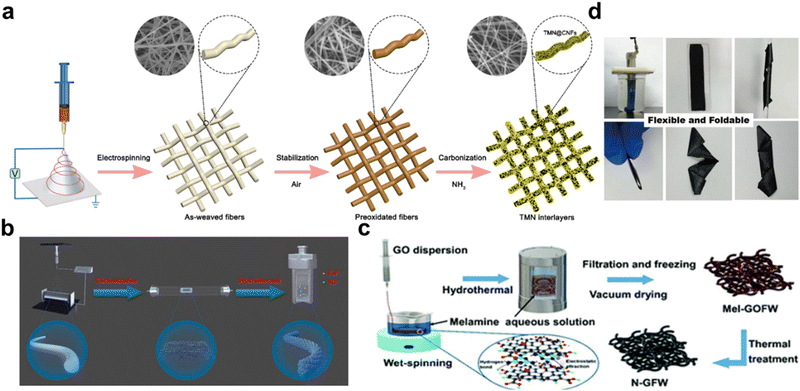 | ||
| Fig. 2 (a) Synthesis route of the TMN@CNF membranes. Reproduced from ref. 19 with permission from the American Chemical Society, copyright 2022. (b) Schematic of the synthetic processes of NiCo2S4-CNF interlayers. Reproduced from ref. 22 with permission from Elsevier, copyright 2021. (c) Schematic illustration of the fabrication procedure of N-GFWs. Reproduced from ref. 25 with permission from The Royal Society of Chemistry, copyright 2019. (d) Fabrication process of PMB SNWs. Reproduced from ref. 26 with permission from Science China Press, copyright 2021. | ||
2.2 Wet spinning
The wet spinning of fibers is typical of dissolving polymer powder in a suitable solvent and extruding the polymer solution into a specific mixture to form fibers. Then, the fiber gets washed, stretched, and dried. As shown in Fig. 2d, Zhang et al. dissolved the Bi2O3-polyoxometalate sub-1 nm nanowires (PMB SNWs) into octane and then prepared 70 μm thick super-aligned PMB NW films through wet spinning. The super-aligned PMB NW interlayers can greatly suppress the shuttling effect and protect the Li anode, endowing the LSBs with an ultralow average capacity decay of 0.013% per cycle when discharging at 2C after 850 cycles.26 As shown in Fig. 2c, Chong et al. prepared an nitrogen-doped graphene fiber web (N-GFW) interlayer by injecting an aqueous GO dispersion to a melamine solution, and heating the mixture for hours, filtration, and freezing at −50 °C. The LSBs with the N-GFW interlayer delivered a remarkable average capacity decay of 0.04% per cycle when discharging at 0.05C after 200 cycles at a sulfur loading of over 2 mg cm−2.252.3 Vacuum filtration
Vacuum filtration is a common method to modify separators by sucking the material onto the separators, but can also be used to fabricate free-standing interlayers after peeling the formed film off and drying. Manthiram group's pioneering work of first introducing the interlayer also used the vacuum filter method for preparation. The synthesized MWCNTs underwent an ultrasonic treatment, followed by a simple vacuum filtration without adding binders, forming a large piece of MWCNT paper when peeled off. This novel introduction of the free-standing MWCNT paper evidently improved both the specific capacity and cycle stability of LSBs, laying a good foundation for future modification of the interlayer, as shown in Fig. 3a.10 As shown in Fig. 3b, Huang et al. sonicated GO and CNTs in distilled water to form uniform dispersion and then obtained GO/CNT films by vacuum filtration. The prepared GO/CNT interlayer was only 30 μm thick and 1.1 mg cm−2 light, but possessed the merits of a porous structure for easy ion transport and electrolyte penetration, oxygenated functional groups for entrapping sulfur species, and highly conductive fast pathways for electron/ion transfer. LSBs with such an interlayer have good performance with a degradation rate of 0.043% per cycle at 0.2C for 300 cycles.27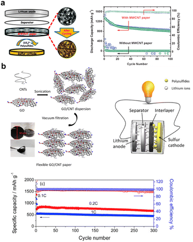 | ||
| Fig. 3 (a) A schematic cell configuration of rechargeable Li–S batteries with MWCNT interlayers, and corresponding high-rate cycle performance and Coulombic efficiency. Reproduced from ref. 10 with permission from The Royal Society of Chemistry, copyright 2012. (b) Schematics for the synthesis of GO/CNT hybrid films, cell configuration of the Li–S battery with an interlayer and cyclic performance, and Coulombic efficiencies at 0.2C and 1C. Reproduced from ref. 27 with permission from Elsevier, copyright 2016. | ||
2.4 Slurry casting
Similar to fabricating a common cathode by casting slurry onto an aluminum foil, the ingredients are dissolved in NMP to form the slurry. After being stirred for some time, the slurry is cast onto the substrate and dried to be a film, then the film gets peeled from the substrate when soaked in liquids and the interlayer is prepared, as typically shown in Fig. 4a.35 Zhou et al. anchored the SS gauze to the substrate glass and coated the PI/MCNT slurry onto SS, preparing the Ni/SS-PI interlayer, which is 10 mg cm−2 light and 100 μm thick. MCNT provides reaction sites for active materials, while the catalytic Ni promotes Li+ diffusion, lowers the overpotential, and accelerates LiPS conversion. LSBs with this interlayer have ultralow average capacity decay of 0.035% per cycle when discharging at 0.5C after 600 cycles at a high sulfur loading of 4.2 mg cm−2.31 Mo et al. coated the slurry containing CFG and Mo2C in CG, and then dried the slurry in a tube furnace, fabricating a CG-CFG@Mo2C interlayer. Mo2C as an electrocatalyst can expedite the reaction kinetics, while the framework of VGSs grown in CFG provides abundant conductive pathways for charge transfer, altogether improving the battery performance. LSBs with such an interlayer show an ultrahigh initial specific discharge capacity of 1632 mA h g−1, a remarkable rate capacity of 755 mA h g−1 at a current density of 3C. The average capacity decay is 0.098% per cycle when discharging at 0.5C after 400 cycles at a sulfur loading of 1.8 mg cm−2.33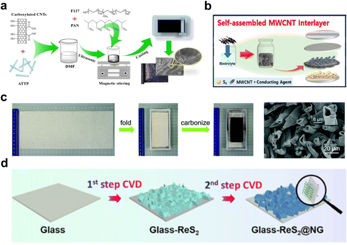 | ||
| Fig. 4 (a) Fabrication scheme of the ATTP/CNTs@PAN interlayer with the slurry casting method. Reproduced from ref. 35 with permission from Elsevier, copyright 2021. (b) Schemes showing the processing of self-assembled MWCNT interlayer. Reproduced from ref. 43 with permission from the American Chemical Society, copyright 2016. (c) The preparation process and cross-sectional SEM image of CCC interlayer. Reproduced from ref. 44 with permission from The Royal Society of Chemistry, copyright 2019. (d) Schematic of a two-step CVD process to in-situ fabricate ReS2@NG heterostructures. Reproduced from ref. 50 with permission from Elsevier, copyright 2019. | ||
2.5 Soaking drying
This method usually dissolves the solute in the corresponding solution, and then soaks the as-prepared substrate in it. After some time, the substrate is taken out and dried. Finally, a specific functional interlayer is fabricated. Yin et al. prepared the GO paper first by the filtering method, and then dissolved aniline and ammonium persulfate in HCl solution, followed by soaking the as-prepared GO paper. 30 minutes later, the paper was taken out and dried at room temperature, forming the final PANI-GO paper as an interlayer, achieving a well-performing battery whose initial capacity was 1261 mA h g−1 and remains at 920.53 mA h g−1 when discharging at 0.5C after 150 cycles.40 Sometimes, the substrate can also be a cathode, forming a facile interlayer directly, which is, however, non-free-standing. Ma et al. simply placed the sulfur cathode in two kinds of solutions and deionized water three times, obtaining a PPy functional interlayer of 10 μm thick, which is a good example of quick fabrication of interlayers.392.6 Self-assembly
The self-assembly method literally means that the ingredients can assemble into a template automatically, so sometimes it is also called the self-template or free-template method. This method applies to materials that can aggregate and form a film or bulk. The reasons behind such behavior include the interacting tendency of long fiber-like materials,54 variable valences,55 electrostatic repulsion, and surface energy56 as well as the absorbance of porous morphology.57 As shown in Fig. 4b, Manthiram et al. added MWCNTs to the prepared electrolyte and applied the mixture directly on the top of the cathode, only taking one step to fabricate the self-assembled MWCNT interlayer at an extremely low cost.43 Due to the good interfacial contact with the sulfur cathode, electron/ion transport is fast, contributing to the effective entrapment and conversion of the migrating polysulfides. LSBs with such interlayers at a sulfur loading of 3 mg cm−2 showed an initial discharge-specific capacity of 1112 mA h g−1 at a 0.1C rate and the average capacity decay was 0.042% per cycle when discharging at 0.5C after 100 cycles.2.7 High-temperature carbonization
Temperature is an important factor impacting the morphology, structure, composition, and character of the material. High-temperature treatment or pyrogenic treatment can evaporate off components with a low boiling point, such as water, out of the original material, forming a shrunk and compact structure. Some carbon-based materials as interlayers get good carbonization treatment after high-temperature processing and show good conductivity, light density, good flexibility, and even hollow inner space, improving the reactional rate and energy density of batteries. As shown in Fig. 4c, our group previously carbonized the cotton cloth at 950 °C to prepare the CCC interlayer. High temperature contributes to the microholes of CCC, increasing the specific surface area and strengthening the confinement ability of polysulfides. LSBs with CCC interlayer demonstrated an ultralow decay rate per cycle of 0.042% when discharging at 1C after 1000 cycles.44 Manthiram et al. carbonized eggshell membranes at 180 °C and then 800 °C, obtaining CSEMs with natural micropores. The CSEMs play the role of the current collector and inhibitor/interlayer, resulting in high discharge capacity (1327 mA h g−1) and long-term cycle stability over 300 cycles at 0.2C at a high sulfur loading of 3.2 mg cm−2.462.8 CVD/ALD
The CVD method is typical of splitting the gas or solid source at a high temperature, doping the target atom, or forming a new compound onto the substrate. In general, the products are thin enough to abandon residual weight, uniformly dispersed, and highly catalytic with a large reaction area, so the interlayers obtained by CVD can easily render a battery with good performance. As shown in Fig. 4d, Wei et al. used a precise CVD to obtain ReS2 and N-doped graphene, successively, on the glass substrate, removed the glass with HF, and introduced PMMA to link the above two to form ReS2 and N-doped graphene heterostructure interlayer. The assembled batteries demonstrated a high initial discharge capacity of 854 mA h g−1 and stable cycling performance with an average capacity decay of 0.064% per cycle after discharging at 2C for 800 cycles. Even at a high sulfur loading of 6.4 mg cm−2, an initial areal capacity of 6.1 mAh cm−2 can be gained.50 Yang et al. applied a low-pressure CVD approach and deposited highly crystalline and atomically thin WS2 on carbon cloth at 1000 °C, getting two kinds of WS2@CC as interlayers. Serving as the active polysulfides catalyst interface, WS2 enables Li–S batteries with excellent rate capability with a high reversible capacity of 793 mA h g−1at a high rate of 2.0C, and stable cycling performance with an average capacity decay of 0.07% per cycle after discharging at 0.5C for 300 cycles.51ALD is mostly similar to CVD, but only deposits a layer of atoms in each reaction at a slower speed, as shown in Fig. 4e.53 Its merits include extraordinary uniformity, accurate atom-scale thickness, and easy reproducibility. The coating materials reported include Al2O3,58 ZnO,52 HfO2,59 and SACo.53
| Modification | Interlayer material | Thickness (μm)/area mass (mg cm−2) | Sulfur areal loading (mg cm−2) | Initial capacity (mA h g−1) | Residual capacity (mA h g−1) | Capacity decay per cycle (%) | Ref. |
|---|---|---|---|---|---|---|---|
| Direct insertion | CCC | —/— | 1.0 | 827 | 498 (1C, 1000 cycles) | 0.042 | 44 |
| MCN | 40–50/0.82–1.11 | — | 1446 | 962 (0.2C, 50 cycles) | 0.670 | 10 | |
| HCF | 90/— | 1.0 | 800 | 733 (0.1C, 100 cycles) | 0.084 | 61 | |
| CC | —/— | 1.0–2.0 | 700 | 510 (2C, 500 cycles) | 0.290 | 62 | |
| Carbon paper | —/3.98 | 1.7 | 1091 | 631 (0.2C, 200 cycles) | 0.210 | 63 | |
| Carbon paper | 85/— | — | 1500 | 810 (0.2C, 50 cycles) | 0.920 | 64 | |
| Treated carbon paper | —/— | — | 1651 | 900 (0.2C, 50 cycles) | 0.910 | 65 | |
| CSNF | 22/— | 2.0 | 1164 | 799 (0.2C, 200 cycles) | 0.160 | 66 | |
| Carbonized cellulose paper | 70/— | 1.4 | 961 | 830 (0.2C, 130 cycles) | 0.100 | 67 | |
| MCP | —/— | — | 1250 | 1062.5 (1C, 100 cycles) | 0.150 | 68 | |
| Physical treatment | PPTA-CA | 272.4 | 2.0 | 1134 | 780.8 (0.2C, 200 cycles) | 0.156 | 69 |
| Polypyrrole-supported carbon paper | 200/— | — | 854 | 555 (0.5C, 200 cycles) | 0.175 | 70 | |
| Atomic doping | N-CCC | —/— | 1.0 | 998 | 762 (2C, 400 cycles) | 0.060 | 71 |
| N-CNF@VN/HNC | —/2.6 | 4.0 | 694 | 610 (0.5C, 500 cycles) | 0.020 | 72 | |
| VN-NWs | 5/— | 1.9 | 1192 | 878 (0.5C, 300 cycles) | 0.015 | 73 | |
| NGQDs/CC | —/— | 1.0 | 1100 | 1000 (0.5C, 300 cycles) | 0.066 | 74 | |
| P-CCC | 290/3.16 | 1.0 | 1058 | 648 (1C, 800 cycles) | 0.046 | 75 | |
| CNT@SACo | 3/0.14 | 1.0 | 880 | 595 (1C, 500 cycles) | 0.064 | 53 | |
| Compound introduction | GO/CNT | 10/0.025 | 1.0 | 851 | 600 (0.5C, 300 cycles) | 0.098 | 49 |
| MoO3/CNF | 30/— | — | 1412 | 600 (1C, 500 cycles) | 0.120 | 76 | |
| MnO2/HCF | 350/— | 0.9 | 780 | 400 (1.7C, 500 cycles) | 0.120 | 77 | |
| MCC–PP | —/— | 1.2 | 1014 | 788.6 (0.5C, 300 cycles) | 0.074 | 78 | |
| SnO2 NWs@CP | —/— | 4.0 | 890 | 801 (0.2C, 300 cycles) | 1.000 | 79 | |
| GF@ZnO | —/0.15 | 1.5 | 1051 | 672 (0.5C, 100 cycles) | 0.360 | 52 | |
| CCC@MoS2 | —/— | 2.0 | 1162 | 1069 (0.5C, 300 cycles) | 0.085 | 80 | |
| CC@CoS2 | —/— | 1.2 | 775 | 610 (4C, 1000 cycles) | 0.021 | 81 | |
| WS2/CCI | —/— | 3.0 | 1300 | 943 (0.5C, 500 cycles) | 0.055 | 82 | |
| CoS2/carbon paper | —/— | 1.5–2.0 | 1240 | 818 (0.2C, 200 cycles) | 0.170 | 83 | |
| ReS2@NG | 0.5/0.08–0.09 | 1.4–1.6 | 854 | 400 (2C, 800 cycles) | 0.064 | 50 | |
| WS2@CC | —/— | 1.0 | 1100 | 870 (0.5C, 300 cycles) | 0.070 | 51 | |
| CoSe2/CC | —/— | — | 851 | 596 (1C, 500 cycles) | 0.060 | 84 | |
| CCC@MoN | —/— | 2.3 | 850.8 | 600.2 (1C, 300 cycles) | 0.098 | 85 | |
| carbon/Fe/Fe3C | —/— | 1.5–1.8 | 850 | 772 (1C, 200 cycles) | 0.460 | 86 | |
| CG-CFG@Mo2C | 1.8 | 1050 | 638 (0.5C, 400 cycles) | 0.098 | 33 | ||
| Co4S3/C@CC | —/— | 1.1–1.5 | 959 | 355 (2C, 1400 cycles) | 0.045 | 87 | |
| UiO-66@CC | —/— | 2.1 | 1033 | 579.2 (1C, 600 cycles) | 0.070 | 88 | |
| MIL-101@CC | —/— | 2.1 | 814 | 655 (1C, 500 cycles) | 0.039 | 89 | |
| ZIF-7@CC | >310/— | 2.1 | 900 | 720 (1C, 500 cycles) | 0.040 | 90 | |
| MOF-801@CC | —/— | 2.0 | 927 | 742 (1C, 500 cycles) | 0.040 | 91 |
3.1 Physical treatment
As an independent component of the battery system, the free-standing interlayer has inherent physical properties of thickness, density, conductivity, morphology, and so on. A thinner, lighter interlayer with a large surface area and better conductivity mean less deterioration of battery energy density, so reasonable physical treatments include adjusting the pore volume and reducing the thickness of the interlayer. Meng et al. fabricated the poly(p-phenylene terephthalamide) (PPTA) nanofiber handsheets at first, and then tailored the pore volume by CO2 treatment.69 As shown in Fig. 5a, CO2 activation turned out to increase the volume of mesopores and micropores, surface area, and oxygen and nitrogen content of carbon papers due to the decomposition of PPTA at a high temperature in the presence of CO2, generating a synergistic inhibition of the shuttle effect of polysulfides through physical adsorption and chemical catalysis. Wu et al. studied the impact of thickness on the interlayer and found that increasing CP thickness leads to improved cycling and rate performance of the battery, as shown in Fig. 5b.70 However, the researchers did not give a valid explanation for the contradiction between the lowest DLi+ and the highest battery performance, and also ignored the essence of thickness-performance impact and its fitting range. Due to the simplicity and repeatability, physical treatments can be performed before the interlayer fabrication by employing porous and ultrathin materials.92,93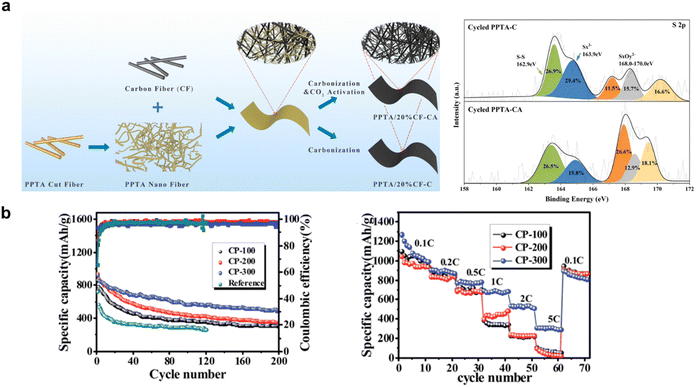 | ||
| Fig. 5 (a) Preparation process of a PPTA/20% CF interlayer, high-resolution S 2p XPS spectra of cycled PPTA-C and cycled PPTA-CA. Reproduced from ref. 69 with permission from the American Chemical Society, copyright 2021. (b) Cycle performance and rate capability of the three different CP cells. Reproduced from ref. 70 with permission from The Royal Society of Chemistry, copyright 2015. | ||
3.2 Atomic doping
Atomic doping is a common strategy to modify the sulfur host, which strengthens the suppression of polysulfides shuttling by forming different chemical bonds.54,94 Similarly, interlayers doped with atoms such as nitrogen, phosphorus, oxygen, cobalt, and even dual and triple atoms, can form Li–N, Li–P, Li–O, and Co–S bonds, meanwhile fulfilling the purpose of physical confinement and chemical entrapment, laying a good foundation for subsequent conversion between polysulfides and sulfur.In our previous works, we treated the as-prepared CCC with ammonia and phytic solution to obtain N-CCC and PCCC, as shown in Fig. 6a and b, respectively.71,75 There existed active sites of pyrrolic N and pyridinic N on N-CCC, respectively, providing a 3D conductive network and Li–N bond with polysulfides, expediting the catalytic reaction kinetics and suppressing the shuttling. In PCCC, the P–S bond could absorb polysulfides chemically, mitigating the polysulfide shuttle and active sulfur loss, achieving a high initial discharge capacity of 1138 mA h g−1 at 0.5C and a good cycling performance with a low capacity decay of 0.054% per cycle when discharging at 1C after 800 cycles. Wang et al. and Park et al. also obtained a nitrogen doping interlayer in the ammonia flow, while Saroha et al. used urea to introduce nitrogen into the interlayer.72–74 ALD is also a good method to dope-specific atoms into the freestanding interlayer. Lin et al. prepared CNT@SACo interlayers by heating a Co-containing precursor at 100 °C, as shown in Fig. 6c. According to the experimental results and first-principles calculations, the randomly dispersed single-atom Co catalysts on the substrate surface enhanced the affinity between polysulfides and the cathode, and improved the reactional conversion kinetics. The LSBs with CNT@SACo interlayers achieved an outstanding performance of low capacity decay of 0.064% per cycle when discharging at 1C after 500 cycles.53
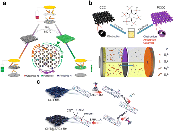 | ||
| Fig. 6 (a) Scheme of the function mechanism of the N-CCC interlayer. Reproduced from ref. 71 with permission from Elsevier, copyright 2021. (b) The schematic of the preparation process of the PCCC interlayers and comparison of the effect to LIPS between the CCC and the PCCC interlayer. Reproduced from ref. 75 with permission from Elsevier, copyright 2020. (c) Schematic illustration of the preparation process of the CNT@SACo interlayer by the ALD method. Reproduced from ref. 53 with permission from the American Chemical Society, copyright 2020. | ||
3.3 Compound introduction
Another approach to forming multiple chemical bonds is to grow compounds to the as-prepared freestanding interlayers, such as the carbon composite, metal compounds including metal oxides, sulfides, carbides, and metal-organic frameworks (MOFs).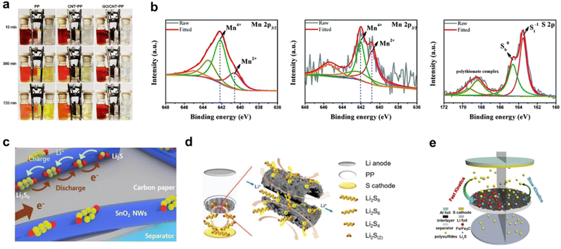 | ||
| Fig. 7 (a) Optical images showing the diffusion process of Li2S6 through PP, CNT/PP, and 25 μg cm−2 GO/CNT-PP films. Reproduced from ref. 49 with permission from Elsevier, copyright 2021. (b) Mn 2p3/2 XPS spectra of MCC composites before, and after soaking tests and the S 2p XPS spectrum of MCC composites after the soaking tests. Reproduced from ref. 78 with permission from The Royal Society of Chemistry, copyright 2021. (c) Schematic description of the adsorption and conversion process of LiPS on the surface of the SnO2 NWs@CP interlayer. Reproduced from ref. 79 with permission from Elsevier, copyright 2020. (d) Schematic illustration of LSBs with the MoS2@CMT interlayer enabling efficient trapping-conversion of polysulfides. Reproduced from ref. 80 with permission from WILEY-VCH, copyright 2020. (e) Schematic illustration of LSBs with carbon/Fe/Fe3C interlayer. Reproduced from ref. 86 with permission from Elsevier, copyright 2019. | ||
Due to the effective catalysis, low cost, and high conductivity, transition metal carbides (TMCs) have also been investigated in the interlayer of LSBs. Zhang et al. decorated the freestanding graphitized carbon interlayers with Fe/Fe3C nanocatalysts by thermal treatment to prepare carbon/Fe/Fe3C interlayers.86 As shown in Fig. 7e, the carbon substrate provides a conductive network for the electron transfer during the electrocatalytic process, and the well-scattered Fe/Fe3C nanoparticles can expedite the electrochemical conversion of polysulfides. LSBs with the carbon/Fe/Fe3C interlayer demonstrate an excellent rate and cycling performance. Mo et al. introduced Mo2C nanoparticles to the CG-CFG substrate by heating the slurry containing the Mo element.33 Similarly, the abundant conductive pathways for charge transfer of the CFG substrate and the high electrocatalysis of Mo2C nanoparticles synergistically improve the battery performance. LSBs with the carbon/Fe/Fe3C interlayer have a high initial specific discharge capacity of 1632 mA h g−1 and a low capacity decay of 0.098% per cycle at 0.5C after 400 cycles at a sulfur loading of 1.8 mg cm−2.
Conclusion and outlook
The poor conductivity of reactant sulfur and the final discharging product Li2S/LiS, the volumetric expansion of the cathode, and the life decay due to the shuttling of polysulfides, all lead to the hampered practical use of LSBs. Extensive work needs to be done to solve the above problems. The introduction of a free-standing interlayer can act as an upper current collector and contribute to a physical barrier to polysulfides shuttling first, and then the modification further enables the interlayer with chemical adsorption/conversion of polysulfides and increases the reaction kinetics. Thus, the use of free-standing interlayers is a good approach to improve the rate performance and cycling stability of LSBs, only at a low cost and a simple manufacturing process.This review summarizes different interlayer fabrication methods and briefly categorizes them into powder-originated and film-originated methods. The powder-originated methods include electrospinning, wet spinning, vacuum filtration, soaking drying, slurry casting, and self-assembly methods. The film-originated methods include high-temperature carbonization, CVD, and ALD methods, which tend to be simpler but introduce more weight to the battery system due to the larger thickness or less pore volume. Among all the methods for fabricating free-standing interlayers, electrospinning is the most frequently reported method in the literature because it is easy to achieve and the product is adequately porous, thin, and light.
However, sometimes the as-prepared free-standing interlayer does not have comprehensive functions of trapping-confining-conversion and increased reaction kinetics, the modification of the as-prepared substrate seems important. We reviewed the modification as physical treatment, atomic doping, and compound introduction. Physical treatment is seldom directly investigated but actually exists generally. Atomic doping concerns various exotic heteroatoms and the corresponding bond formation. The compound introduction covers carbon composite, metal oxides, metal sulfides, metal carbides, and MOFs. Among them, the carbon composite shows good electrical conductivity but is poorly catalytic. Metal oxides have good adsorption ability toward polysulfides but are also bad catalytically. Metal sulfides and metal carbides are both good in conductivity, adsorption, and catalysis. MOFs are highly catalytic but poor in electrical conductivity.
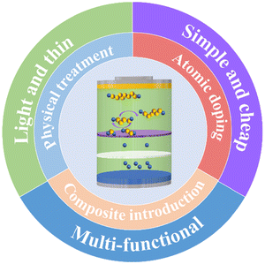
When it comes to the outlook of how to use a free-standing interlayer effectively and efficiently, the free-standing interlayer should meet the following merits (Fig. 9).
(1) Light and thin. The introduction of an interlayer increases the overall weight of the battery system and correspondingly reduces the gravimetric/volumetric energy density of the whole battery. Lightweight is necessary, typical of low thickness, large pore volume, and low-density materials.
(2) Simple and cheap. For further practical use, the cost must be low enough by choosing the cheap ingredient, reducing the manufacturing complexity, and avoiding huge energy consumption.
(3) Multifunctional. To deal with the common drawbacks of LSBs, an excellent interlayer should possess a good electrical conductivity, strong adsorption and conversion ability of polysulfides, and high catalytic kinetics, achieving outstanding rate performance and enduring cycling life.
Conflicts of interest
There is no conflict to declare.Acknowledgements
This work was supported by the Natural Science Foundation of Guangdong Province (No. 2019A1515011573).References
- B. J. van Ruijven, E. De Cian and I. S. Wing, Nat. Commun., 2019, 10, 2762 CrossRef PubMed.
- Y. Lu, H. Shi, Y. Su, S. Zhao, L. Chen and F. Wu, Prog. Chem., 2021, 33, 1598–1613 CAS.
- H. Hong, N. A. R. Che Mohamad, K. Chae, F. Marques Mota and D. H. Kim, J. Mater. Chem. A, 2021, 9, 10012–10038 RSC.
- D. Herbert and J. Ulam, US Pat., 3043896, 1962 Search PubMed.
- J. R. Birk and R. K. Steunenberg, Adv. Chem., 1975, 140, 186–202 CAS.
- M. S. Whittingham, Science, 1976, 192, 1126–1127 CrossRef CAS PubMed.
- E. Peled, Y. Sternberg, A. Gorenshtein and Y. Lavi, J. Electrochem. Soc., 1989, 136, 1621–1625 CrossRef CAS.
- Y. V. Mikhaylik and J. R. Akridge, J. Electrochem. Soc., 2004, 151, A1969–A1976 CrossRef CAS.
- X. Ji, K. T. Lee and L. F. Nazar, Nat. Mater., 2009, 8, 500–506 CrossRef CAS PubMed.
- Y. S. Su and A. Manthiram, Chem. Commun., 2012, 48, 8817–8819 RSC.
- Sion Power's Lithium-Sulfur Batteries Power High Altitude Pseudo-Satellite Flight, https://www.businesswire.com/news/home/20140922005174/en/Sion-Power%E2%80%99s-Lithium-Sulfur-Batteries-Power-High-Altitude-Pseudo-Satellite-Flight, (accessed September, 2014).
- Y. Hao, D. Xiong, W. Liu, L. Fan, D. Li and X. Li, ACS Appl. Mater. Interfaces, 2017, 9, 40273–40280 CrossRef CAS PubMed.
- G. Babu, K. Ababtain, K. Y. S. Ng and L. M. R. Arava, Sci. Rep., 2015, 5, 8763 CrossRef CAS PubMed.
- N. Li, L. Yu and J. Xi, Small, 2021, 17, 2103001 CrossRef CAS PubMed.
- L. Yang, Q. Li, Y. Wang, Y. Chen, X. Guo, Z. Wu, G. Chen, B. Zhong, W. Xiang and Y. Zhong, Ionics, 2020, 26, 5299–5318 CrossRef CAS.
- About Us-Batteries for Electric Vehicles from Lyten, https://lyten.com/company/about-us/, (accessed September, 2021).
- Lyten to launch Li-S battery for 2025/26-electrive.com, https://www.electrive.com/2021/09/28/lyten-to-launch-li-s-battery-for-2025-26/, (accessed September, 2021).
- D. Zhu, T. Long, B. Xu, Y. Zhao, H. Hong, R. Liu, F. Meng and J. Liu, J. Energy Chem., 2021, 57, 41–60 CrossRef.
- Y. Zhu, X. Wu, M. Li, Y. Ji, Q. Li, X. He, Z. Lei, Z. Liu, R. Jiang and J. Sun, ACS Sustainable Chem. Eng., 2022, 10, 776–788 CrossRef CAS.
- X. Jiang, S. Zhang, B. Zou, G. Li, S. Yang, Y. Zhao, J. Lian, H. Li and H. Ji, Chem. Eng. J., 2022, 430, 131911 CrossRef CAS.
- J. Zhu, Y. Liu, L. Zhong, J. Wang, H. Chen, S. Zhao and Y. Qiu, J. Electroanal. Chem., 2021, 881, 116483 CrossRef.
- X. Zhang, L. Zhu, Z. Gao, L. Zhang, Z. Zhang, L. Zhang and Y. Wang, Mater. Today Commun., 2021, 28, 102666 CrossRef CAS.
- H. Yoon, D. Park, H. J. Song, S. Park and D. W. Kim, ACS Sustainable Chem. Eng., 2021, 9, 8487–8496 CrossRef CAS.
- X. Wang, Y. Luo, H. Wang, C. Wu, Z. Zhang and J. Li, J. Electroanal. Chem., 2021, 897, 115564 CrossRef CAS.
- W. G. Chong, F. Xiao, S. S. Yao, J. Cui, Z. Sadighi, J. X. Wu, M. Ihsan-Ul-Haq, M. H. Shao and J. K. Kim, Nanoscale, 2019, 11, 6334–6342 RSC.
- S. Zhang, H. Shi, J. Tang, W. Shi, Z. S. Wu and X. Wang, Sci. China Mater., 2021, 64, 2949–2957 CrossRef CAS.
- J. Q. Huang, Z. L. Xu, S. Abouali, M. Akbari Garakani and J. K. Kim, Carbon, 2016, 99, 624–632 CrossRef CAS.
- Z. Sun, Y. Guo, B. Li, T. Tan and Y. Zhao, Solid State Sci., 2019, 95, 105924 CrossRef CAS.
- D. K. Lee, S. J. Kim, Y. J. Kim, H. Choi, D. W. Kim, H. J. Jeon, C. W. Ahn, J. W. Lee and H. T. Jung, Adv. Mater. Interfaces, 2019, 6, 1801992 CrossRef CAS.
- Y. Li, P. Zhou, H. Li, T. Gao, L. Zhou, Y. Zhang, N. Xiao, Z. Xia, L. Wang, Q. Zhang, L. Gu and S. Guo, Small Methods, 2020, 4, 1900701 CrossRef CAS.
- Z. Zhou, Z. Chen, Y. Zhao, H. Lv, H. Wei, B. Chen, Z. Gu and Y. Wang, Nanoscale, 2022, 14, 700–714 RSC.
- D. Versaci, I. Canale, S. Goswami, J. Amici, C. Francia, E. Fortunato, R. Martins, L. Pereira and S. Bodoardo, J. Power Sources, 2022, 521, 230945 CrossRef CAS.
- Y. Mo, J. Lin, S. Li and J. Yu, Chem. Eng. J., 2022, 433, 134306 CrossRef CAS.
- X. Yang, T. Qin, X. Zhang, X. Liu, Z. Wang, W. Zhang and W. Zheng, Chem. Res. Chin. Univ., 2021, 37, 259–264 CrossRef CAS.
- Q. Xie, J. Zhang and P. Zhao, J. Electroanal. Chem., 2021, 898, 115629 CrossRef CAS.
- J. Yang, F. Chen, C. Li, T. Bai, B. Long and X. Zhou, J. Mater. Chem. A, 2016, 4, 14324–14333 RSC.
- K. Zou, N. Li, X. Dai, W. Jing, M. Shi, C. Lu, Q. Tan, Y. Xin, J. Sun, Y. Chen and Y. Liu, ACS Appl. Nano Mater., 2020, 3, 5732–5742 CrossRef CAS.
- E. Alhajji, W. Wang, W. Zhang and H. N. Alshareef, ACS Appl. Mater. Interfaces, 2020, 12, 18833–18839 CrossRef CAS PubMed.
- G. Ma, Z. Wen, J. Jin, M. Wu, X. Wu and J. Zhang, J. Power Sources, 2014, 267, 542–546 CrossRef CAS.
- L. X. Yin, H. Dou, A. X. Wang, G. Y. Xu, P. Nie, Z. Chang and X. G. Zhang, New J. Chem., 2018, 42, 1431–1436 RSC.
- H. Zhong and L. Zhang, Mater. Lett., 2022, 310, 131499 CrossRef CAS.
- G. Ma, Z. Wen, Q. Wang, C. Shen, P. Peng, J. Jin and X. Wu, J. Power Sources, 2015, 273, 511–516 CrossRef CAS.
- H. M. Kim, J. Y. Hwang, A. Manthiram and Y. K. Sun, ACS Appl. Mater. Interfaces, 2016, 8, 983–987 CrossRef CAS PubMed.
- B. Zheng, N. Li, J. Yang and J. Xi, Chem. Commun., 2019, 55, 2289–2292 RSC.
- S. Azam, Z. Wei and R. Wang, J. Colloid Interface Sci., 2022, 615, 417–431 CrossRef CAS PubMed.
- S. H. Chung and A. Manthiram, Adv. Mater., 2014, 26, 1360–1365 CrossRef CAS PubMed.
- S. H. Chung and A. Manthiram, ChemSusChem, 2014, 7, 1655–1661 CrossRef CAS PubMed.
- R. Chen, Y. Zhou and X. Li, Nano Lett., 2022, 22, 1217–1224 CrossRef CAS PubMed.
- B. Xu, Y. Zhao, H. Liu, S. Cheng, J. Liu and F. Meng, Mater. Lett., 2021, 305, 130753 CrossRef CAS.
- N. Wei, J. Cai, R. Wang, M. Wang, W. Lv, H. Ci, J. Sun and Z. Liu, Nano Energy, 2019, 66, 104190 CrossRef CAS.
- M. E. Pam, S. Huang, S. Fan, D. Geng, D. Kong, S. Chen, M. Ding, L. Guo, L. K. Ang and H. Y. Yang, Mater. Today Energy, 2020, 16, 100380 CrossRef.
- R. Yi, C. Liu, Y. Zhao, L. J. Hardwick, Y. Li, X. Geng, Q. Zhang, L. Yang and C. Zhao, Electrochim. Acta, 2019, 299, 479–488 CrossRef CAS.
- Q. Lin, B. Ding, S. Chen, P. Li, Z. Li, Y. Shi, H. Dou and X. Zhang, ACS Appl. Energy Mater., 2020, 3, 11206–11212 CrossRef CAS.
- J. Q. Huang, W. G. Chong, B. Zhang and X. Ma, Mater. Today Commun., 2021, 28, 102566 CrossRef CAS.
- R. R. Li, H. J. Peng, Q. P. Wu, X. J. Zhou, J. He, H. J. Shen, M. H. Yang and C. L. Li, Angew. Chem., Int. Ed., 2020, 59, 12129–12138 CrossRef CAS PubMed.
- C. Yao, Y. Sun, K. Zhao, T. Wu, A. Mauger, C. M. Julien, L. Cong, J. Liu, H. Xie and L. Sun, RSC Adv., 2018, 8, 3443–3452 RSC.
- J. Wu, N. You, X. Li, H. Zeng, S. Li, Z. Xue, Y. Ye and X. Xie, J. Mater. Chem. A, 2019, 7, 7644–7653 RSC.
- X. Han, Y. Xu, X. Chen, Y. C. Chen, N. Weadock, J. Wan, H. Zhu, Y. Liu, H. Li, G. Rubloff, C. Wang and L. Hu, Nano Energy, 2013, 2, 1197–1206 CrossRef CAS.
- W. Kong, D. Wang, L. Yan, Y. Luo, K. Jiang, Q. Li, L. Zhang, S. Lu, S. Fan, J. Li and J. Wang, Carbon, 2018, 139, 896–905 CrossRef CAS.
- Y. S. Su and A. Manthiram, Chem. Commun., 2012, 48, 8817–8819 RSC.
- Q. Meng, R. Yang, Y. Liu, M. Li, S. Chen and Y. Yan, Int. J. Energy Res., 2021, 46, 5296–5305 CrossRef.
- Z. Nie, H. Zhang, Y. Lu, C. Han, Y. Du, Z. Sun, Y. Yan, H. Yu, X. Zhang and J. Zhu, Chem. Eng. J., 2021, 409, 128137 CrossRef CAS.
- Y. Li, L. Meng, L. Jin, L. Yun and H. Jian, Mater. Res. Express, 2019, 6, 125547 CrossRef CAS.
- K. Zhang, Q. Li, L. Zhang, J. Fang, J. Li, F. Qin, Z. Zhang and Y. Lai, Mater. Lett., 2014, 121, 198–201 CrossRef CAS.
- C. Zu, Y. S. Su, Y. Fu and A. Manthiram, Phys. Chem. Chem. Phys., 2013, 15, 2291–2297 RSC.
- K. Wu, Y. Hu, Z. Cheng, P. Pan, L. Jiang, J. Mao, C. Ni, X. Gu and Z. Wang, J. Membr. Sci., 2019, 592, 117349 CrossRef CAS.
- S. Li, G. Ren, M. N. F. Hoque, Z. Dong, J. Warzywoda and Z. Fan, Appl. Surf. Sci., 2017, 396, 637–643 CrossRef CAS.
- Y. S. Su and A. Manthiram, Nat. Commun., 2012, 3, 1166 CrossRef PubMed.
- L. Meng, Y. Li, Q. Lin, J. Long, Y. Wang and J. Hu, ACS Appl. Energy Mater., 2021, 4, 8592–8603 CrossRef CAS.
- F. Wu, W. Li, L. Guan, Y. Ye, J. Qian, X. Yang, Y. Xu and R. Chen, RSC Adv., 2015, 5, 94479–94485 RSC.
- N. Li, L. Yu, J. Yang, B. Zheng, X. Qiu and J. Xi, Nano Energy, 2021, 79, 105466 CrossRef CAS.
- R. Saroha, J. H. Oh, Y. H. Seon, Y. C. Kang, J. S. Lee, D. W. Jeong and J. S. Cho, J. Mater. Chem. A, 2021, 9, 11651–11664 RSC.
- P. Wang, Z. Zhang, B. Hong, K. Zhang, J. Li and Y. Lai, J. Electroanal. Chem., 2019, 832, 475–479 CrossRef CAS.
- J. Park, J. Moon, V. Ri, S. Lee, C. Kim and E. J. Cairns, ACS Appl. Energy Mater., 2021, 4, 3518–3525 CrossRef CAS.
- B. Zheng, L. Yu, N. Li and J. Xi, Electrochim. Acta, 2020, 345, 136186 CrossRef CAS.
- H. Li, X. Wang, C. Qi, C. Zhao, C. Fu, L. Wang and T. Liu, Phys. Chem. Chem. Phys., 2020, 22, 2157–2163 RSC.
- G. J. Chao, L. S. Zhang, S. J. Yuan, T. T. Xue, F. Yang, Y. P. Huang, W. Fan and T. X. Liu, ACS Appl. Energy Mater., 2020, 3, 12703–12708 CrossRef CAS.
- H. Liu, H. Cheng, H. Jin, C. Gao, P. Zhang and M. Wang, Mater. Adv., 2021, 2, 688–691 RSC.
- H. Ahn, Y. Kim, J. Bae, Y. K. Kim and W. B. Kim, Chem. Eng. J., 2020, 401, 126042 CrossRef CAS.
- J. Yang, L. Yu, B. Zheng, N. Li, J. Xi and X. Qiu, Adv. Sci., 2020, 7, 1903260 CrossRef CAS PubMed.
- J. Xu, L. Yang, S. Cao, J. Wang, Y. Ma, J. Zhang and X. Lu, Adv. Sci., 2021, 8, 2101019 CrossRef CAS PubMed.
- J. Park, B. C. Yu, J. S. Park, J. W. Choi, C. Kim, Y. E. Sung and J. B. Goodenough, Adv. Energy Mater., 2017, 7, 1602567 CrossRef.
- Z. Ma, Z. Li, K. Hu, D. Liu, J. Huo and S. Wang, J. Power Sources, 2016, 325, 71–78 CrossRef CAS.
- Z. Ren, Z. Zhao, K. Zhang, X. Wang and Y. Wang, ChemElectroChem, 2021, 8, 1531–1536 CrossRef CAS.
- X. Zhou, J. L. Yang, N. Li, J. Yang and J. Xi, Mater. Today Energy, 2022, 24, 100941 CrossRef CAS.
- Y. J. Zhang, J. Qu, Q. Y. Ji, T. T. Zhang, W. Chang, S. M. Hao and Z. Z. Yu, Carbon, 2019, 155, 353–360 CrossRef CAS.
- J. Liu, Y. Song, C. Lin, Q. Xie, D. L. Peng and R. J. Xie, Sci. China Mater., 2021, 65, 947–957 CrossRef.
- S. Zheng, X. Zhao, G. Liu, F. Wu and J. Li, Nanotechnology, 2021, 32, 365404 CrossRef CAS PubMed.
- F. Zhang, T. Niu, F. Wu, L. Wu, G. Wang and J. Li, Electrochim. Acta, 2021, 392, 139028 CrossRef CAS.
- X. Wang, Y. Zhao, F. Wu, S. Liu, Z. Zhang, Z. Tan, X. Du and J. Li, J. Energy Chem., 2021, 57, 19–27 CrossRef.
- G. Jin, J. Zhang, B. Dang, F. Wu and J. Li, Front. Chem. Sci. Eng., 2021, 16, 511–522 CrossRef.
- J. Balach, T. Jaumann, M. Klose, S. Oswald, J. Eckert and L. Giebeler, J. Phys. Chem. C, 2015, 119, 4580–4587 CrossRef CAS.
- X. Yu, G. Zhou and Y. Cui, ACS Appl. Mater. Interfaces, 2019, 11, 3080–3086 CrossRef CAS PubMed.
- Y. Liu, H. J. Wei, X. L. Zhai, F. Wang, X. Y. Ren, Y. Xiong, O. Akiyoshi, K. M. Pan, F. Z. Ren and S. Z. Wei, Mater. Des., 2021, 211, 110171 CrossRef CAS.
- X. Zhou, F. Chen and J. Yang, J. Energy Chem., 2015, 24, 448–455 CrossRef.
- G. Chao, L. Zhang, S. Yuan, T. Xue, F. Yang, Y. Huang, W. Fan and T. Liu, ACS Appl. Energy Mater., 2020, 3, 12703–12708 CrossRef CAS.
- M. Tian, F. Pei, M. Yao, Z. Fu, L. Lin, G. Wu, G. Xu, H. Kitagawa and X. Fang, Energy Storage Mater., 2019, 21, 14–21 CrossRef.
- Y. Zheng, S. Zheng, H. Xue and H. Pang, J. Mater. Chem. A, 2019, 7, 3469–3491 RSC.
| This journal is © the Owner Societies 2022 |


