
 Open Access Article
 This Open Access Article is licensed under a Creative Commons Attribution-Non Commercial 3.0 Unported Licence
The impact of ligands on the synthesis and application of metal halide perovskite nanocrystals
Fatima
Haydous
 ,
James M.
Gardner
* and
Ute B.
Cappel
*
,
James M.
Gardner
* and
Ute B.
Cappel
*
Division of Applied Physical Chemistry, Department of Chemistry, KTH – Royal Institute of Technology, SE-100 44 Stockholm, Sweden. E-mail: jgardner@kth.se; cappel@kth.se
First published on 18th October 2021
Abstract
Metal halide perovskites have emerged as attractive materials for use in solar cells, light emitting diodes and other optoelectronic devices, mainly due to their impressive charge transport properties, strong light absorption, long carrier diffusion lengths and long excited state lifetime. The extensive research on these materials has paved the way for a new class of materials: metal halide perovskite nanocrystals (NCs). Due to their high photoluminescence quantum yield and narrow emission that can be tuned by size and compositional variations, perovskite NCs are considered to be ideal candidates compared to traditional quantum dots. With the growing interest in these materials and the current challenges in their commercialization, this review aims mainly to provide the necessary understanding of the influence of capping ligands on the synthesis and application of perovskite NCs. The different synthetic approaches and the role of ligands in determining the morphological and optical properties of the resulting NCs will be discussed. Thereafter, we review the advances in understanding the surface chemistry and ligation in the metal halide perovskite NCs. Lastly, we review the ligand exchange and management processes that are shown to be beneficial in improving the performance and stability of perovskite nanocrystal films for optoelectronic applications.
 Fatima Haydous | Dr Fatima Haydous holds a B.Sc. in Chemistry from the Lebanese University (2011) and a M.Sc. degree in Physical Chemistry from the American University of Beirut, Lebanon (2014). In 2018, she received her PhD degree from the Department of Chemistry at ETH-Zurich, Switzerland under the supervision of Prof. Thomas Lippert. Afterwards, she worked as a postdoctoral fellow at KTH Royal Institute of Technology, Sweden with Dr James Gardner and Dr Ute Cappel. Her current research interests focus on the synthesis and characterization of inorganic nanomaterials as perovskites and fabrication of thin films for solar energy applications including solar cells and solar water splitting. |
 James M. Gardner | Dr James M Gardner received his PhD in Physical, Inorganic, and Materials Chemistry from The Johns Hopkins University in 2009. He joined the faculty of the Department of Chemistry at KTH Royal Institute of Technology in 2011 as an Assistant Professor. Since 2016, he has been the Associate Professor of Photoelectrochemistry in the Division of Applied Physical Chemistry at KTH. That same year, James became Deputy Head of the Center for Molecular Devices (CMD). The CMD is a collaborative research environment between KTH and Uppsala University that focuses on all aspects of emerging solar cell technologies. His current research interests focus on photochemistry and photophysics of interfaces. Of particular interest is understanding the energetics, kinetics, and conditions that promote interfacial charge transfer chemistry as this relates to dye-sensitized solar cells and perovskite solar cells. |
 Ute B. Cappel | Dr Ute Cappel received her PhD in Chemistry at Uppsala University in 2011. Following a Marie-Curie fellowship at Imperial College London, she was a researcher at the Department of Physics and Astronomy at Uppsala University. In 2017, she became an Assistant Professor at the Department of Chemistry at KTH Royal Institute of Technology and was promoted to Associate Professor in 2020. Her research focuses on the characterization of materials for and processes in hybrid solar cells, in particular lead halide perovskites and quantum dots. She uses synchrotron-based photoelectron spectroscopy to study the chemical and electronic structure of surfaces and interfaces. |
1. Introduction
During the last decades, nanoscale materials have become essential in our daily lives, as they are embraced in most of our daily practices1–3 including cosmetics,4,5 biological applications (e.g. biosensors),6–8 electronic and optoelectronic devices (like smart phones and displays).9–11 The reason behind the interest in these materials and their great potential in all of these applications are their outstanding properties due to their large surface-to-volume ratio in comparison to their corresponding bulk materials. Semiconductor nanocrystals (NCs) can exhibit unique properties such as high extinction coefficients, rapid charge separation, good chemical/thermal/environmental stability, and ease of synthesis. Typically, the solution-based synthesis of NCs requires surface passivating molecules known as capping ligands, which bind to the surface of the NCs to control crystal size and isolate them from their environment. The produced NCs have versatile surface chemistries that allow for dispersion in different solvents and which enable their integration into various matrices and devices. Another key advantage is the quantum confinement effect, in which the electron and hole are confined in the NC. This is primarily observed in quantum dots (QDs), which are semiconductor NCs with a size usually in the range of 2–10 nm that confines electron–hole pairs in all three dimensions. Due to this effect, these NCs exhibit discrete energy levels similar to those of atoms or molecules and the light absorption and energy levels can be tuned through the size of the crystals.12In parallel, the continued research on new materials has led to novel solutions for overcoming the increasing global energy demands. Even though metal halide perovskites (MHPs) were discovered more than 40 years ago, the interest in these materials was stimulated by the 2012 reports in which MHPs were successfully used as light absorbers in solar cells.13–15 The attractive properties of MHPs including the long carrier diffusion lengths, strong light absorption, impressive charge transport and tuneable bandgap through compositional variations promoted a vast amount of research in this field.15,16 Due to the fast developments in the application of MHPs in solar cells, a certified record efficiency more than 25% was achieved within only one decade of development compared to several decades for other solar cell technologies.17 MHPs are appealing materials not only in photovoltaics but also in LEDs, photodetectors, lasers and other optoelectronic applications, where a significant progress had been also reported.18–24
Researchers have shown that a synergetic effect can be realized by combining the advantages of these two classes of materials: perovskites and nanocrystals.25 Extensive research has therefore concentrated on the synthesis, characterization and application of MHP NCs and particularly lead halide perovskite NCs, which may substitute traditional metal chalcogenide NCs in some applications.26 Perovskite NCs exhibit intriguing properties ranging from low fabrication cost, simple and facile synthesis, outstanding photoluminescence quantum yields (PLQY) and narrow emission. Their bandgap can be tuned to match the whole visible light region via composition modification and crystal size control.26,27 Moreover, compared to bulk MHPs, NCs are considered beneficial in several aspects. Firstly, surface effects can stabilize the cubic perovskite crystal structure, which would be unstable as the bulk material.13 Secondly, NCs show enhanced PLQY compared to their bulk counterparts with PLQY limited by mobile ionic defects and small exciton binding energy.14 These properties make them interesting materials for next generation photovoltaic and light emitting devices.
With the rapid advances in this field, there have been several reviews during the previous years revealing the potential of MHPs in the form of NCs.9,13,14,16,28 The main focus of these reviews was the synthesis of the perovskite NCs and their applications. Recently, more specific reviews have been published encountering precise issues related to metal halide perovskite nanocrystals, such as doping with lanthanide,29 using mesoporous matrices as hosts for the nanocrystals30 and lead-free halide nanocrystals.31 Even though ligands have a profound effect on the growth and morphological, structural and optoelectronic properties perovskite NCs, the type of interaction between the perovskite nanocrystals and capping ligands has been significantly less discussed. Thus, this review will shed light on the surface chemistry of the perovskite nanocrystals and the role of ligand modification in determining the growth, optical and morphological properties of the nanocrystals and therefore their application.
Based on that, the review is divided into five main parts. The first part addresses ligation and the different types of ligands used in the synthesis of MHP NCs. The second part gives a brief overview of the structural and optoelectronic properties of MHP NCs and their stability. In the third part, a summary of the different synthesis approaches of MHP NCs will be given with the focus on the influence of ligands in controlling the morphology and composition of the NCs. The fourth part will describe the surface chemistry of MHP NCs and the NC–ligand interaction and its influence on the purification procedure of the NCs. The last section will detail the ligand management procedures that have been applied to improve the performance and stability of optoelectronic devices based on MHP NC films. Finally, we will conclude the review by discussing the remaining open issues and providing an outlook on the future directions in this field.
2. Ligands
Ligands are molecules or ions that bind to a metal atom or ion forming a coordination complex. These molecules or ions are usually used in the synthesis of NCs, where they bind to the NCs surface to stabilize them and compensate for their high surface to-volume ratio. In this section we will introduce the most common ligands for MHP NCs and their binding types.The bonding between ligands and metals varies from covalent to ionic bonding. In this regard, the different types of bonding between the ligands and surface states of the NCs can be described using the Covalent Bond Classification (CBC) that was proposed initially by Green32 to describe metal–organic complexes. Based on this model, ligands can be divided in three categories: a Z-type ligand with an empty orbital that acts as a Lewis acid accepting an electron pair from an anion site at the NC surface, an L-type ligand which is considered as a Lewis base with a filled orbital that donates two electrons to an unoccupied surface metal orbital and an X-type ligand which forms a covalent bond with a singly occupied orbital on the surface.33,34
Fig. 1 shows an overview of different types of ligands that have been used for stabilizing MHP NCs and that will be considered in this review.
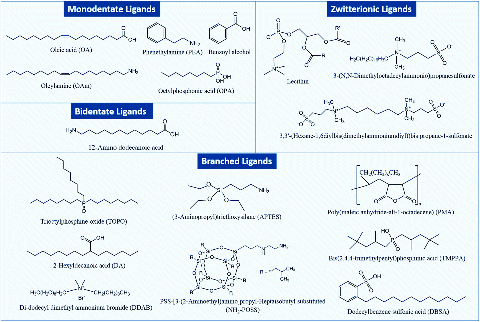 | ||
| Fig. 1 Chemical structures of different types of capping ligands for MHP NCs. | ||
In general, two types of ligands are used in the synthesis of MHP NCs: carboxylic acids which prevent coagulation of the NCs through steric repulsion and amines that are integral in controlling the crystallization of the NCs.35 Such monodentate ligands consist of a long alkyl tail or a phenyl group and a polar head which binds to an atom or ion at the surface of the NC. NCs can be also capped with bidentate and multidentate ligands which can bind to two or more atoms or ions at the NC surface. These ligands have a stronger binding to the NC surface compared to the monodentate ones, which leads to less structural distortions at the NC surface and as a consequence stabilizing the NCs more effectively.36,37
Besides the aforementioned ligands, branched ligands have been investigated as they enable a better control of the NC size and uniformity compared to ligands with straight chains. Another type of ligand is the zwitterionic ligand, which has several functional groups at the same end of the molecule that can anchor simultaneously to the NC surface. As a result, these ligands have a stronger interaction with the NC surface in comparison to ligands with one coordinating group. Moreover, ligands can be anions (such as halides, S2−, SCN− and NH2−) or cations (such as NO+ and N2H5+).38–44 Indeed, as will be discussed later, the carboxylic acid and amine ligands used in the synthesis of MHP NCs bind to the NCs surface as carboxylate anions and ammonium cations, respectively. These ionic ligands influence the nature of trapping sites at the surface of the NCs and passivate them to improve the photoluminescence and stability of NCs.
3. Perovskite nanocrystals
In this section, we discuss the structural and optoelectronic properties and the stability of perovskite NCs. These properties will be addressed throughout the review while discussing the influence of ligands on the synthesis and application of MHP NCs.3.1 Crystal structure
Analogous to oxide perovskites, MHPs of the overall ABX3 formula (with A being a large monovalent cation, B an inorganic-metal cation and X a halide anion such as Cl−, Br−, I−) consist of a three-dimensional (3D) network of corner sharing BX6 octahedra (Fig. 2a). In the cubic void between the corner sharing octahedra one or more A cation forms ionic bonds to the anionic BX64− network. Most of the studied MHP NCs are based on Pb2+ at the B-site. These lead halide perovskite (LHP) NCs can be classified depending on the type of the A cation into three groups: hybrid organic–inorganic, all-inorganic and mixed perovskites. Hybrid organic–inorganic LHP NCs contain an organic ammonium cation at the A-site of the perovskite such as: methylammonium (MA+) and formamidinium (FA+). All-inorganic lead halide perovskites are isostructural to the hybrid perovskite with A being an inorganic cation such as Cs+ or Rb+. In mixed LHP NCs, the composition of the A cation can be adjusted by using different ammonium cations45,46 or by incorporating both inorganic and organic cations.47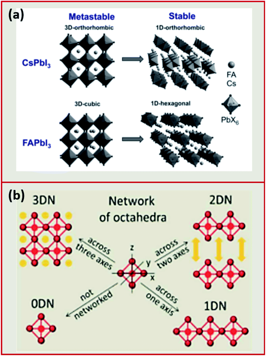 | ||
| Fig. 2 (a) Illustration of the 3D to 1D phase transition in CsPbI3 and FAPbI3. Reproduced with permission from ref. 27. (b) Schematic presenting the differences between the different dimensionalities (0DN, 1DN, 2DN and 3DN) depending on the connectivity of the octahedra. Reproduced with permission from ref. 56. | ||
Alternative to LHP NCs, MHP NCs based on more environmentally friendly metal cations at the B-site (Sn2+, Ge2+, Sb3+, Bi3+, In3+, Cu+ or Ag+) replacing Pb2+ became highly desirable. However, these lead-free perovskite NCs suffer from oxidative instability, indirect or large band gaps, and synthesis difficulties since they compete with more thermodynamically favourable phases.13 In addition, they still show inferior properties compared to Pb-based perovskite NCs (i.e. less defect tolerance and hence lower PLQY).31
MHPs are typically observed in three 3D polymorphs: cubic, tetragonal and orthorhombic with the cubic phase existing at the highest temperature.13 The stability of the perovskite phases can be predicted using the Goldschmidt tolerance (t) and the octahedral factor (μ) factors.48–50 The latter is determined from the ratio of the ionic radii of the B cation (rB) over the halide (rX) such that: μ = rB/rX. When this factor ranges between 0.41 and 0.89, the BX64− octahedra, and thereby the perovskite structure, are considered stable.51 On the other hand, the tolerance factor depends additionally on the ionic radii of the A-site cation (rA) according to the following equation:
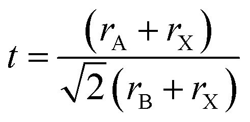
This factor has been extensively used to predict the stability of perovskite structures through assessing if the A-site cation fits in the voids of the framework.48,49 For t values between 0.8 and 1.0, the octahedra are stable resulting in a stable perovskite structure. The perovskite is cubic when t is close to one, otherwise, the octahedra will partially tilt resulting in orthorhombic or tetragonal structures. Only the cubic and tetragonal 3D polymorphs are interesting for optoelectronic applications as they are photoactive exhibiting the desired semiconducting properties.49,50 As an example, the 3D polymorphs, of CsPbI3 and FAPbI3 are metastable at room temperature (RT). This is because the size of A cations for these two near-IR emitting perovskites are at the borderline for optimal 3D perovskite structure; with Cs+ ion being too small (t ∼ 0.89 for CsPbI3) and FA+ being too large (t ∼ 1 for FAPbI3).27,50,52 Therefore, these two materials easily undergo a phase transition at RT to their more stable phases; FAPbI3 to a one-dimensional (1D) hexagonal phase and CsPbI3 to a 1D orthorhombic phase (illustrated in Fig. 2a27,48). These two phases, known as “yellow phases” have wider band gaps than the 3D motifs and show poor electron transport which limits the full utilization of CsPbI3 and FAPbI3 in devices.13,50 Nonetheless, it was shown that the polymorph stability of MHPs can be adjusted in NCs because of the governing surface effects. The cubic phase of CsPbI3 was shown to be stabilized at RT in ambient air for several months in CsPbI3 QDs and QD films due to the contribution of surface energy.50,53 In this way, the under-coordinated surface sites or bound ligands can affect bonding geometries for the entire crystal.
In addition to the 3D MHP polymorphs, low dimensional NCs have been synthesized by tailoring the composition of the MHPs.31,54 These NCs exhibit a variety of shapes such as: zero-dimensional (0D) QDs, one-dimensional (1D) nanowires (NWs) or nanorods (NRs) and two-dimensional (2D) nanosheets (NSs) or nanoplatelets (NPLs).50,55 Compared to the corner sharing octahedra in 3D perovskites, the connectivity of the octahedra in the lower dimensions is presented in Fig. 2b. The low dimensional NCs are usually more stable than 3D NCs against environmental factors such as moisture.56 However, the 3D polymorphs of MHPs are more interesting than the 2D and 1D motifs because they exhibit more appealing semiconductor properties (e.g. suitable bandgap and good electron transport) that are desirable for optoelectronic applications.50
3.2 Optoelectronic properties
In this part, we discuss the different optoelectronic properties of MHP NCs that are of interest for their application in devices. These properties, as will be shown in Sections 5 and 6, are affected by the ligands binding to the NCs and therefore can be tailored depending on the application of the NCs via ligand control.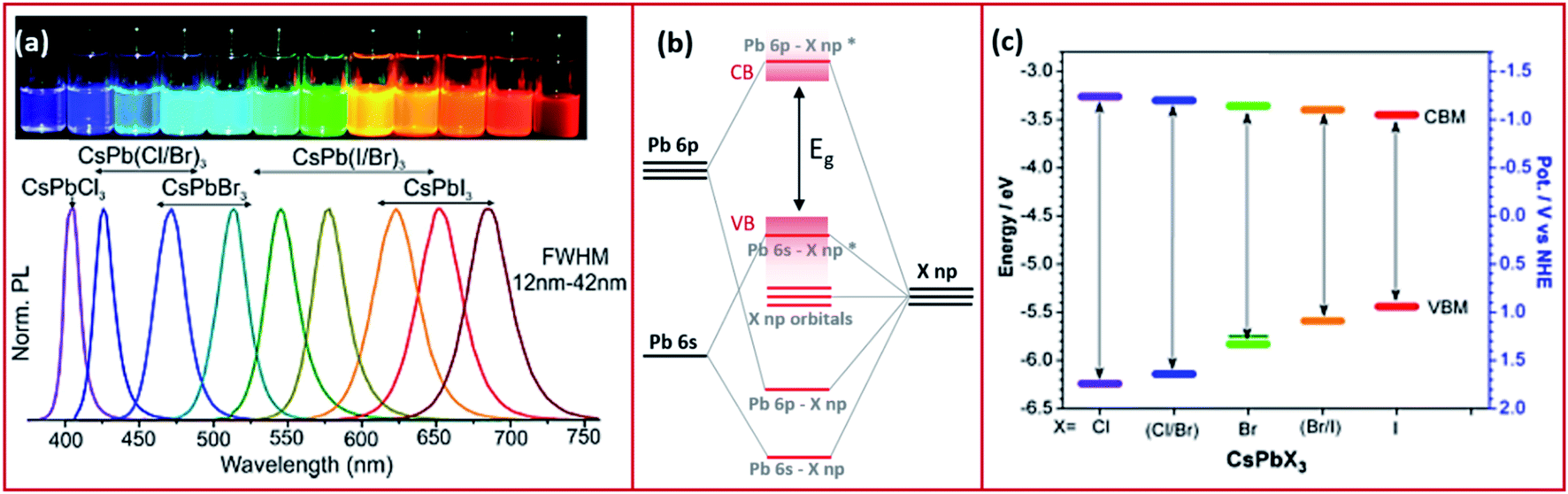 | ||
| Fig. 3 (a) The PL spectra of CsPbX3 NCs with variable halide content with the corresponding image of the different NC solutions in toluene under UV illumination. Reproduced with permission from ref. 57. (b) A schematic representing the electronic structure of lead halide perovskites. (c) Band edge energies (conduction band CBM and valence band VBM) of CsPbX3 NCs extracted from cyclic voltammetry measurements with a scan rate of 50 mV s−1 of the NCs dispersed in tetra-butyl ammonium perchlorate electrolyte in a mixture of acetonitrile and toluene. Modified with permission from ref. 63. | ||
The optical properties of the MHP NCs are also influenced by the cation at the B-site of the perovskite. For instance, the band gap was shown to be red shifted when replacing Pb2+ with Sn2+ most probably because of the higher electronegativity of the latter cation.64 Other examples include partial substitution of Pb2+ or complete substitution forming lead-free MHP NCs that modify the optical properties of their LHP alternates.31,65
Even though the A cation of the perovskite does not contribute to the density of states (DOS) of the CB and VB, it can influence the band gap.66 The decrease of the size of the A cation (for example from FA+ to MA+ to Cs+) was shown to increase the band gap of LHP.66 This is ascribed to the increase in the tilting angle of the Pb–X–Pb bonding that is associated to the distortion of the cubic crystal structure.67
Perovskite NCs have narrow emissions with line widths that are less than 100 meV which is essential for lighting applications.57 Also, compared to their bulk counterparts, MHP NCs exhibit extremely high PLQY values.60 PLQY of nearly 100% have been observed for caesium and methylammonium lead bromide or iodide NCs and values of 70–90% have been achieved for FA+-based NCs.68–73 In comparison, chloride-based perovskite NCs exhibit lower PLQY (below 20%) because of the changes in the crystal structure associated with the smaller size of Cl−, and the non-radiative trapping sites due to defects that are less shallow compared to other halide perovskites.14
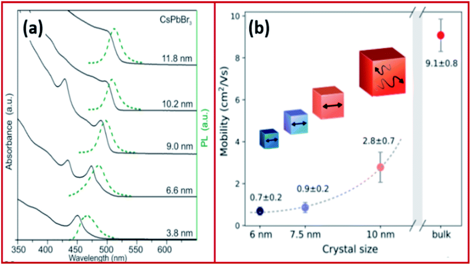 | ||
| Fig. 4 (a) Absorption and emission of CsPbBr3 NCs with variable size demonstrating quantum-size effects. (b) Size dependence of effective charge-carrier mobility of CsPbBr3. Panels (a) and (b) are reproduced with permission from ref. 57 and 81, respectively. | ||
The Bohr diameter of Wannier–Mott type excitons, estimated according to the effective mass approximation, was found to be 5, 7 and 12 nm for CsPbCl3, CsPbBr3 and CsPbI3 NCs and 1.5–3 nm for MAPbBr3 and MAPbI3 NCs.57,74,75 As a result, the confinement in LHP NCs which are typically in the form of 4–15 nm nanocubes is usually negligible or very low. For instance, the exciton binding energies of CsPbCl3, CsPbBr3, CsPbI3 nanocubes were determined to be 75, 40 and 20 meV, respectively, which are comparable to those of their bulk counterparts and to MAPbI3 with an exciton binding energy of ≤25 meV.57,76–79 However, in the case of nanosheets and nanowires, the confinement becomes more significant due to the use of long chain ligands, which enable the synthesis of very thin nanosheets (few monolayers) and nanowires of small diameters (less than 10 nm). A high exciton binding energy of 120 meV was measured for 3.4 nm thick CsPbBr3 nanoplatelets demonstrating a strong confinement in one dimension.76,80
Studying the PLQY values of perovskite NCs along with their PL decay dynamics gives insights regarding the radiative and non-radiative recombination processes and therefore understanding the defects and trap states in these NCs.30 As in any semiconductor material, the lifetime of excited states in MHP NCs is usually shorter than that of its bulk counterpart. In the case of inorganic CsPbX3 NCs, time-resolved PL measurements show a bi-exponential decay with a radiative lifetime in the nanosecond range between 1 and 29 ns. The PL lifetime of these NCs increases with the decrease of the band gap.13,57,82 In comparison, organic LHP NCs exhibit longer lifetimes with FAPbI3, MAPbI3 and MAPbBr3−xClx (x = 0.6–2) NCs, for instance, showing decay lifetimes of 70, 100 and 40–400 ns, respectively.48,57 Mixed organic–inorganic LHP NCs such as FA0.1Cs0.9PbI3 exhibit radiative lifetimes of 51 ns.48 Lead-free MHP NCs show comparable PL decay lifetimes to LHP NCs.31
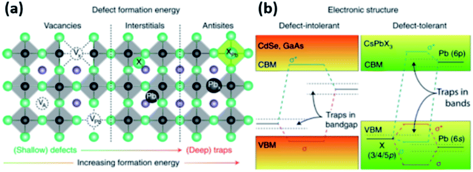 | ||
| Fig. 5 (a) The typical point defects present in LHPs ordered with respect to their formation energies and positions in the band gap. (b) Schematic illustration showing the differences in the electronic structures of defect intolerant semiconductors (such as metal chalcogenides) and defect tolerant MHPs. Reproduced with permission from ref. 28. | ||
3.3 Stability
With all the promising optoelectronic properties and the achieved progress in the synthesis of MHP NCs, the full implementation of their potential remains restricted by their limited stability. MHP NCs are highly vulnerable to polar solvents, which threaten their optical properties and long-term structural integrity.13,88 Yuan et al.,89 for instance, showed that the use of certain antisolvents in the postsynthetic cleaning steps of CsPbBr1−xIx perovskite NCs can modify their halide content and thereby their overall optical properties.In addition, MHP materials exhibit poor chemical stability and are highly sensitive to moisture, light, and elevated temperatures. This was shown to limit the practical application of bulk MHPs in highly efficient solar cells.90,91 The stability of the hybrid MAPbI3, for example, is influenced by its decomposition into volatile HI and CH3NH2.13 In addition, MHP NCs can degrade in the presence of a combination of light, and oxygen because of the diffusion of photogenerated O2− anion into the halide vacancy sites promoting the oxidation of the perovskite.92 Moreover, of certain concern is the thermal instability of LHP NCs because of their low melting point where sintering of films based on NCs makes them densely packed losing in some cases their structural integrity and quantum properties.
Since the stability of MHP NCs is a prerequisite for their efficient application in devices, several approaches have been investigated to improve the stability of these NCs. One approach is to combine NCs with different classes of materials such as polymers,93–105 graphene,106–111 2D materials,112–115 silica116–120 and alumina.121–126 The formation of nanocomposites through embedding LHP NCs in organic polymers as effective matrices allows a low transmission rate of oxygen and moisture.127,128 Furthermore, to avoid the chemical instability associated with MAPbX3 NCs, the MA+ cations are replaced by FA+ and Cs+. However, this imposes another form of instability which is the structural instability discussed above. As will be shown in Sections 5 and 6, the stability of MHP NCs in polar solvents and under ambient conditions can be improved through ligand modification and engineering.
4. Perovskite nanocrystal synthesis
Several synthetic approaches have been used and developed to produce MHP NCs. These methods can be divided into two main categories: colloidal (or non-template) and non-colloidal (or template-based) synthesis. The different synthesis routes will be discussed in this section along with the factors affecting the control over the size and shape of the NCs with the main emphasis on the impact of ligands.4.1 Colloidal synthesis
Colloidal synthesis is a simple wet chemistry process where the ionic precursors are mixed under controlled temperature to form an insoluble precipitate. This well-established technique consists of different possible synthesis pathways for NCs with the two most common approaches being the hot injection (HI) and ligand-assisted reprecipitation (LARP) methods.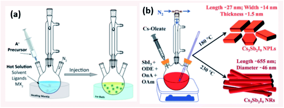 | ||
| Fig. 6 (a) Schematic illustrating the HI method (b) Scheme presenting the HI synthesis of Cs3Sb2I9 NPLs and NRs at different temperatures using octanoic acid (OnA) and oleylamine (OAm) ligands in 1-octadecene (ODE). Panels (a) and (b) are taken with permission from ref. 14 and 134, respectively. | ||
Protesescu et al.57 applied this synthesis by injecting Cs-oleate into a solution of PbX2 (with X being different halides such as Cl, Br, I) with equal ratios of OA and OAm ligands in the presence of octadecene (ODE) at temperatures in the range between 140 °C and 200 °C and reported the formation of monodisperse CsPbX3 nanocubes with sizes between 4 and 15 nm. The resulting NCs were shown to have a cubic perovskite structure and a tuneable band gap through size and compositional modulation. In addition, they exhibited a narrow photoluminescence emission with full width at half maximum (FWHM) of 12–42 nm (Fig. 3a) and high PL quantum yields of 50–90%.57 Following this report, the HI method was extended to other MHP NCs such as CH3NH3PbX3 (MAPbX3 with X being Br or I) by injecting methylammonium solution instead of Cs-oleate to the PbX2 precursor solution.133
4.1.1.1 Control of size and shape of NCs in HI method. The size, size-distribution and shape of the NCs synthesized by the HI method can be controlled by several parameters. The main factors are the temperature at which the cation or anion precursor is injected and the time at which the reaction is stopped. For example, the morphology of Cs3Sb2I9 NCs was tuned by varying the temperature where NPLs were produced at 180 °C and NRs at a higher temperature of 230 °C (Fig. 6b).134 Due to the rapid growth of CsPbX3 NCs, their size was shown to be tuned mainly by the temperature rather than the growth time.135 Bekenstein et al.136 reported the synthesis of green-emitting CsPbBr3 nanocubes at 150 °C using the HI method. At lower temperatures, anisotropic growth of the NCs proceeds favouring the growth of quasi 2D geometries, where cyan-emitting NPLs were formed at 130 °C and very thin blue-emitting NPLs were formed at 90–100 °C with lamellar structures (Fig. 7a).136 In another study, the thickness of CsPbBr3 NPLs was tuned at a monolayer level by varying the temperature and the lateral dimensions were varied by modifying the reaction time.137 In general, at higher temperatures, CsPbBr3 nanocubes are formed in the initial stage (first 10 minutes). Then, NWs are formed for a reaction time up to several hours after which large crystals start to form.138 As demonstrated in Fig. 7b, different intermediate morphologies can coexist at a certain time.138
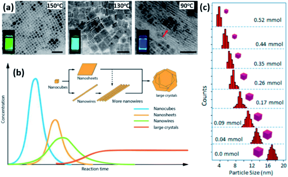 | ||
| Fig. 7 (a) TEM images of CsPbBr3 NCs grown at different temperatures with photos of the solutions under UV-illumination in the inset of the figures. The scale bar is 50 nm. (b) A sketch illustrating the morphology evolution during the synthesis of CsPbBr3 NCs by HI approach. (c) Size distribution histogram of CsPbBr3 nanocubes obtained at 160 °C from the reaction with varying amounts of oleylammonium bromide. Panels (a), (b) and (c) are adapted with permission from ref. 136, 138 and 140, respectively. | ||
Another key parameter in controlling the size of the MHP NCs in HI method is the initial precursors used and their relative concentrations. Studies have demonstrated that the use of ZnBr2 or alkyl ammonium bromide as extra halide sources in the synthesis resulted in a better control of the size and size distribution of CsPbBr3 nanocubes, as shown in Fig. 7c.139,140
4.1.1.2 Role of ligands in size and shape control of NCs. Long-chain organic acids and bases, mainly OA and OAm, are typically used in the HI synthesis: first to solvate the inorganic precursors in the non-coordinating solvent, then to adjust the size and shape of the synthesized NCs by modifying the reaction kinetics and lastly to stabilize the produced colloidal NCs by acting as surface ligands.89,141 A recent study on II–VI and III–V QDs has shown that the NC–ligand interaction is essential in determining the optoelectronic properties of the QDs.34 Therefore, varying the concentration of ligands, their type and chain length can significantly influence the structure, size, shape, optical properties and stability of the NCs.
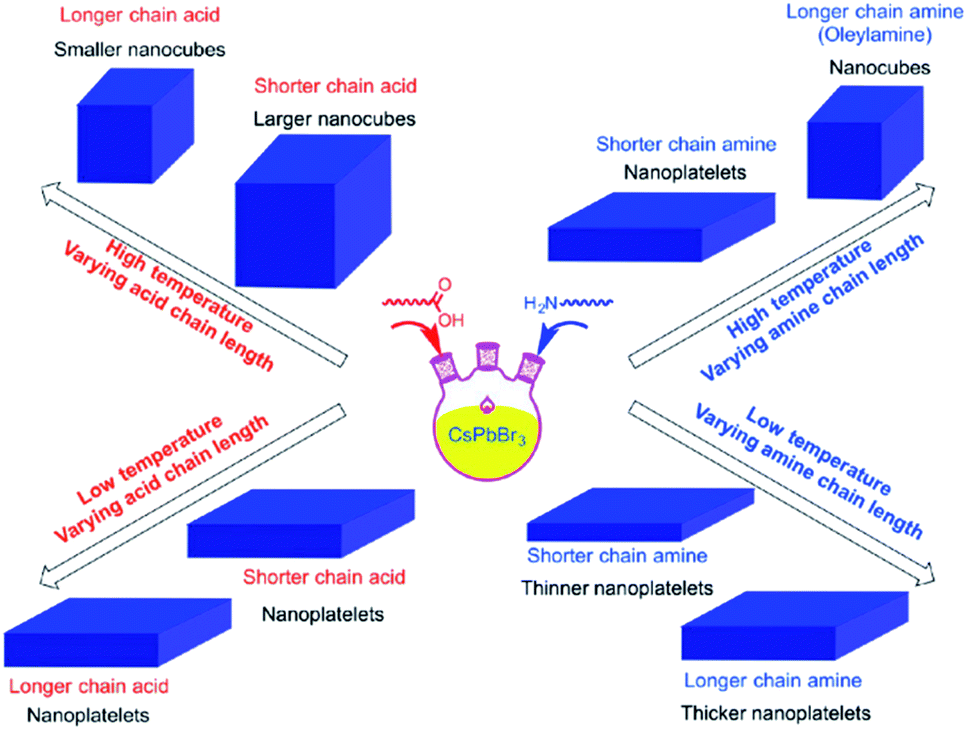
It was reported that shortening the chain length of the carboxylic acid ligands used in the synthesis, without varying OAm, increases the size of the CsPbBr3 nanocubes produced at high temperatures. Alternatively, while keeping the amount of OA fixed, the length of the amine alkyl chain was shown to affect the shape of the NCs. Nanoplatelets were formed in all cases except when using OAm at high temperature where nanocubes are produced (Fig. 8).141 From this it can be suggested that the shape selectivity depends on the chain length of the amines more than the carboxylic acids.141 Similarly, Song et al.142 demonstrated the synthesis of 1 μm CsPbBr3 NSs that are atomically thick by employing dodecylamine and OA in the HI synthesis and prolonging the reaction time.
 | ||
| Fig. 8 Schematics illustrating the effect of temperature and type of ligand on the size and shape of NCs synthesized by the HI approach. The figure is reprinted with permission from ref. 141. | ||
A comprehensive study was conducted by Almeida et al.143 to clarify the effect of ligand concentration on the shape, size and size distribution of CsPbBr3 NCs. They reported that reducing the concentration of OA and OAm ligands to the minimum amount required to dissolve PbBr2 suppressed the Ostwald ripening resulting in nanocubes with narrow size distribution with size ranging between 4 to 16.4 nm. NPLs were not observed under this condition (reduced concentration of ligands) regardless of the temperature. However, increasing the concentration of both ligands enhanced the solubility of PbBr2 resulting in the formation of 0D Cs4PbBr6 NCs.143 These results were then confirmed by Huang et al.144 who showed that the control over the size and thereby the quantum confinement of MAPbBr3 NCs can be achieved by a fine control of the ligand/precursor ratio.
Other examples include the synthesis of CsPbBr3 NWs by Imran et al.145 where the width of the NWs was regulated between 10–20 nm (nonconfined) by controlling the reaction time and the octylamine/OAm ratio. Adding long alkyl chain acid (OA) with these amines resulted in the formation of NSs. However, if a carboxylic acid with a shorter alkyl chain (e.g. octanoic acid or hexanoic acid) was added to the amine ligands, thin NWs were produced with their width decreasing down to 3.4 nm (highly confined) when increasing the amount of short acid with respect to the amines.145 In another study, it was shown that using octylamine and octanoic acid as ligands with short alkyl chains and in addition to OA and OAm resulted in the formation of nanosheets that are a few nm thick. While the thickness stayed constant, the lateral dimensions of the nanosheets was varied from 200 nm to few micrometers by changing the ratio of the amount of short ligands with respect to OA and OAm.146
Furthermore, the type of capping ligand can affect the size and shape of the NCs synthesized by HI approach. For instance, Park et al.147 investigated the effect of exchanging the pristine OA and OAm ligands on CsPbBr3 NCs synthesized using the HI approach with branched quaternary ammonium bromide ligands. The results showed that the NCs capped with OA/OAm or branched ligands were all monodispersed nanocubes. However, the size of the NCs increased with increasing the bulkiness of the ligands due to the lower coverage of the NC surface with the bulkier ligands, which induces rapid attachment of the remaining precursors resulting in the growth of the NCs.147 In another study, it was shown that employing branched ligands, such as triethylamine (TEAm), inhibited the formation of MAPbBr3 nanoplatelets whereas octylamine ligand facilitated the formation of NPLs.148 Studies showed that NCs capped with zwitterionic and bidentate ligands exhibit improved colloidal stability compared to monodentate ligands.149,150
In the case of MHP NCs, the LARP process consists of dissolving the precursor salts (typically MX2 with M being Pb, Sn, etc., CsX, MAX and FAX where X is Cl, Br or I) in a polar solvent (as dimethylformamide (DMF), dimethylsulfoxide (DMSO)) and adding it to a nonpolar solvent (such as toluene or hexane) in the presence of ligands. Mixing the two solvents triggers immediate saturation that induces the nucleation and growth of the MHP NCs (Fig. 9a).151,153,154
 | ||
| Fig. 9 (a) Illustration of the LARP synthesis. (b) The variation of PL maxima with the amount of alkylamine employed in the synthesis of MAPbBr3 NPLs for different lengths of the alkyl chain of alkylamine. (c) TEM images, photographs of the NPLs under UV light, PL and UV-visible absorption spectra revealing the decrease in their thickness with the increase of octylammonium concentration (from 0 to 100%). Panels (a), (b) and (c) are modified with permission from ref. 14, 157 and 158. | ||
Indeed, shortly before the first study on the HI synthesis of CsPbX3 NCs,57 Schmidt reported the LARP synthesis of highly crystalline MAPbBr3 NCs in the form of 6 nm-sized spherical nanoparticles.88 The synthesis consisted of a simple procedure where solutions of MABr and PbBr2 dissolved in DMF were subsequently added to a heated solution of the ligands in ODE. The formed dispersion was then precipitated by acetone.88 This technique is highly versatile, as it was extended to other MHPs forming ABX3 NCs of variable compositions (A = Cs, MA or FA, B = Pb, Bi, Sn or Sb and X = Cl, Br or I) and shapes (NPLs, NWs and NRs).11,14,71,153,155,156
4.1.2.1 Role of ligands on the size and shape control of NCs. To investigate the role of ligands in the LARP approach, Zhang et al.58 conducted the synthesis of MAPbBr3 NCs under different conditions by varying the ligands used in the precursor solution. The results showed that the NCs could be produced by the LARP approach when excluding the amines from the synthesis, yet control over the size was not achieved in that case. The absence of carboxylic acids in the synthesis resulted in aggregated NCs. Therefore, the amines were suggested to be used to regulate the kinetics of the crystallization and thereby the size of the NCs, whereas the acids contributed to the stability of the colloids suppressing the NCs from aggregation.58
Similar to the HI approach, it was found that higher ligand concentration in the LARP synthesis, the size of the NCs is reduced. Also, in both approaches (except at low temperatures in the HI method), the NCs become smaller, at least in one dimension, when the alkyl chain length of the ligand is increased.
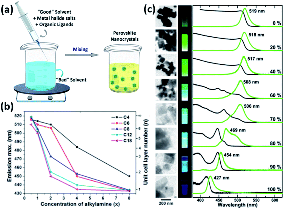
For instance, the effect of ligand concentration and chain length on the morphological properties of MAPbBr3 NPLs prepared using LARP approach was inspected by Cho et al.157 The thickness of the NPLs was shown to be extremely dependent on the concentration and chain length of alkylamines (Fig. 9b). Longer amines and higher concentrations passivated the surface of the NCs more efficiently suppressing its growth in the vertical direction and allowing its growth only laterally.157 Similarly, the thickness of MAPbBr3 NPLs, produced by reacting PbBr2 with MABr and octylammonium bromide in the absence of carboxylic acid ligand, was shown to be proportional to the ratio of MA to octylammonium (Fig. 9c). When only octylammonium was used, “single layered” NPLs were obtained.158
Moreover, it was shown that the crystal structure and composition is greatly influenced by the amount of ligands used in the LARP synthesis. Chen et al.159 revealed that by increasing the ligand content, the products changed completely from the monoclinic 3D CsPbX3 phase to the hexagonal 0D Cs4PbX6 phase. This was explained by the steric hindrance resulting from the increased OA and OAm in the precursor solutions making it difficult for the PbX64− octahedrons to come together and produce the 3D structure. Indeed, it was shown that OAm has a greater role in such phase transition than OA, most likely because of the attraction of Cs+ to the lone-pair on the N atom in the amino head group of OAm resulting in more separation of the PbX64− octahedrons forming thereby the 0D phase.159
Other modifications to the LARP technique included the use of auxiliary ligands as benzoyl alcohol in addition to OA and octylamine. This ligand was shown to facilitate the reaction and enhance the PLQY of the produced NCs.148 Peptides with –NH2 and –COOH ending groups were also utilized in the LARP synthesis for a better control of the NCs' size. For instance, 12-aminododecanoic acid was used as the only capping ligand in synthesizing MAPbBr3 NCs.160 Using 2-adamantylammoniun bromide (ADBr) as the only capping ligand for the LARP synthesis of MAPbBr3 NCs resulted in a 100% PLQY revealing the full passivation of the surface of the NCs.69 Luo et al.161 synthesized MAPbX3 NCs using the LARP approach with replacing OA ligand with (3-aminopropyl)triethoxysilane (APTES) and polyhedral oligomeric silsesquioxane (POSS) PSS-[3-(2-aminoethyl)amino]propylheptaisobutyl substituted (NH2-POSS). These branched ligands result in the formation of smaller NCs with a better uniformity than those prepared using straight-chain ligands. The authors demonstrated the size dependence of the NCs on the amount of APTES ligand where smaller MAPbX3 nanocubes were obtained with increasing the amount of APTES due to the steric hindrance which makes the delivery of monomers to the NCs slower during the growth stage. In addition, steric hindrance and repulsion between the branched ligands increases, on one hand, the number of uncoordinated atoms at the surface of NCs lowering thereby their PLQY compared to the straight-chain ligands. On another hand, it hinders the access of solvent molecules to the NC surface, hence improving their stability compared to NCs ligated with OA.161
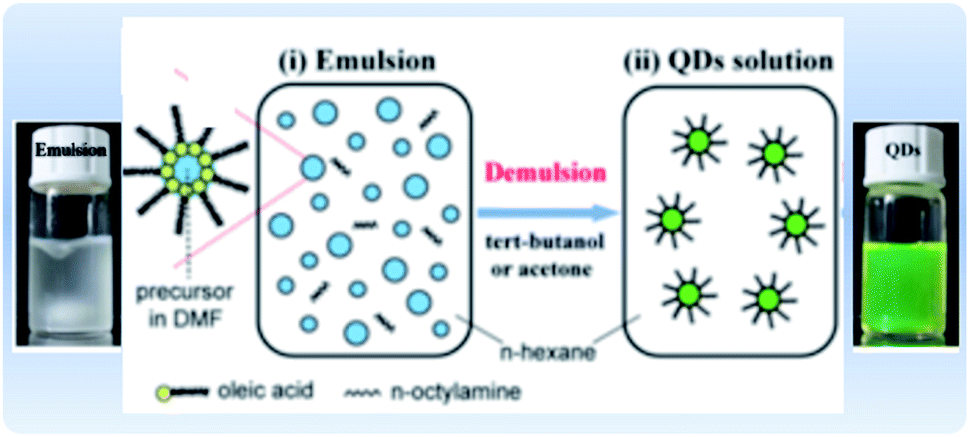
4.1.2.2 Emulsion LARP. An alternative approach for the synthesis of MHP NCs is through a modified LARP synthesis, termed “emulsion LARP”. In this approach, as presented in Fig. 10, the precursors are dissolved in two different solvents (containing the ligands) that are immiscible, unlike the classical LARP process. When mixing the two solutions, an emulsion is formed. Upon adding a de-emulsifier that is miscible in both solvents, the reaction starts by driving the system to a supersaturation state allowing the nucleation and precipitation of the NCs.49,152,162,163 Huang et al.162 used the emulsion LARP approach to synthesize MAPbBr3 NCs by mixing the “aqueous phase” consisting of MABr and PbBr2 dissolved in DMF with the “oil phase” that is OA and n-octylamine in hexane. Acetone and tert-butanol could be added as de-emulsifiers to the emulsion to initiate the recrystallization and formation of the NCs. In an analogous manner, this method was used for the synthesis of CsPbX3, MAPbX3 and FAPbBr3 NCs with different morphologies (spherical QDs, nanocubes, NPLs and NWs).153,163–165 The method could be advantageous over conventional LARP in that it does not require that the solvents be miscible.
 | ||
| Fig. 10 Illustration of the emulsion synthesis method and photographs of the MAPbBr3 emulsion and the resultant colloidal solution upon addition of the demulsifier. Modified with permission from ref. 162. | ||
4.1.2.3 Polar solvent controlled ionization. In this approach, unlike the LARP method, the precursors (e.g. metal oleates and alkyl ammonium halides) are not dissociated in a polar solvent in the beginning of the synthesis. Instead, they are dispersed in a nonpolar solvent such as hexane. A polar solvent is then subsequently added to the precursors resulting in their dissociation into ions forming the NCs. Therefore, this method is advantageous over LARP strategy in using a smaller amount of polar solvents. CsPbX3 NCs synthesized by this approach exhibited PLQY over 80% and tuneable emission covering the visible range via compositional modifications.166
4.1.3.1 Heat-up methods. Other synthetic routes have been developed by researchers in which a mixture containing all the precursors, ligands and solvents is heated or ultrasonicated to produce the NCs under an air atmosphere and at a gram scale with high PLQY.68,137,167–173 These methods, similar to HI, required ligands based on both carboxylic acids and alkyl amines.14
The solvothermal method was demonstrated by Chen et al.172via the synthesis of CsPbX3 NCs by heating up a mixture containing caesium carbonate or acetate and PbX2 salts with the ligands in an autoclave. The obtained NCs were in the form of nanocubes, when the precursors were heated directly in the autoclave without predissolving. However, when the precursors were dissolved prior to heating, a higher concentration of precursor ions was achieved resulting in more nuclei upon heating with the formation of CsPbX3 NWs as the result. The NWs were also obtained by prolonging the reaction time when the precursors were not predissolved.172
Tong et al.68 employed a single step ultrasonication-assisted synthesis (Fig. 11a) to produce CsPbX3 NCs with a variable halide composition and morphology. They showed that CsPbBr3 nanocubes were transformed into NWs by prolonging the reaction time.174 Furthermore, modifying the initial conditions, such as the Cs2CO3![[thin space (1/6-em)]](https://www.rsc.org/images/entities/char_2009.gif) :PbX2 ratio, in the ultrasonication synthesis of CsPbX3 NCs enabled tuning the fluorescence of the NCs and modifying their shape and size, as presented in Fig. 11b.68 The impact of ligands in the ultrasonication synthesis was also investigated. Employing shorter ligands (such as octylamine) instead of OAm increased the size of MAPbBr3 NCs with a wide size distribution (20–50 nm). Besides, the study revealed that increasing the amount of OAm ligand reduced the size of the NCs forming QDs as evidenced by the TEM images in Fig. 11c.171
:PbX2 ratio, in the ultrasonication synthesis of CsPbX3 NCs enabled tuning the fluorescence of the NCs and modifying their shape and size, as presented in Fig. 11b.68 The impact of ligands in the ultrasonication synthesis was also investigated. Employing shorter ligands (such as octylamine) instead of OAm increased the size of MAPbBr3 NCs with a wide size distribution (20–50 nm). Besides, the study revealed that increasing the amount of OAm ligand reduced the size of the NCs forming QDs as evidenced by the TEM images in Fig. 11c.171
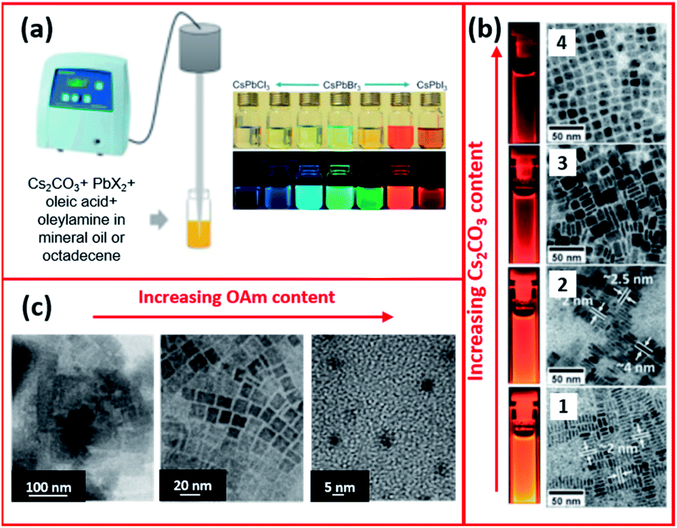 | ||
| Fig. 11 (a) Schematics of the single-step tip sonication method and photograph of the synthesized CsPbX3 NCs. (b) TEM images (from 1 to 4) of CsPbI3 NCs prepared by ultrasonication method using increasing amounts of Cs2CO3 with respect to PbI2. (c) TEM images showing the different morphologies of MAPbBr3 NCs synthesized by the ultrasound approach with increasing amount of OAm. Panels (a) and (b) are modified with permission from ref. 68 and panel (c) from ref. 171. | ||
The microwave irradiation method (Fig. 12a) was adopted and modified by several scientists for the synthesis of CsPbX3 NCs in various morphologies.168–170,173 The shape and size of NCs synthesized using the microwave irradiation can be controlled by modifying the irradiation time and power.168,170 Long et al.170 showed that initially by increasing the irradiation time, the shape of the CsPbI3 NCs changed from being irregular nanocubes to larger regular nanocubes (Fig. 12b). The size of the nanocubes was increased with extending the irradiation time until the time where over-irradiation triggered the destruction of the CsPbI3 NCs. The power of the microwave irradiation was shown to strongly influence the PLQYs of the perovskite NCs as shown in Fig. 12c. Additionally, the ligands played a significant role in this method. For instance, changing the amount of OAm used in the synthesis modified the morphology of the NCs as seen in Fig. 12d.170
 | ||
| Fig. 12 (a) Illustrations of the microwave-assisted synthesis of CsPbX3 NCs. (b) STEM images of CsPbI3 NCs with increasing microwave irradiation time. (c) A photograph of the CsPbI3 NC solutions, under day light and UV light, prepared by microwave irradiation at different powers. (d) TEM images showing the different morphologies of CsPbI3 NCs prepared by the microwave irradiation approach using increased amounts of OAm. Figure modified with permission from ref. 170. | ||
4.1.3.2 Indirect two-step synthesis from NC seeds. In addition to the aforementioned colloidal synthetic approaches, indirect two-step synthesis of MHP NCs starting from colloidal NC seeds had been demonstrated.175,176 For instance, pre-synthesized CsX NCs were used as seeds for the growth of CsPbBr3 NCs by reacting with Pb-oleate.175 Similarly, 2D and 3D LHP NCs were produced by reacting PbI2 NCs with MAI or alkyl ammonium.176 This strategy is beneficial in that the easy synthesis and tuning of the parent NCs' size enables a good control of the size of MHP NCs and allows the formation of MHP NCs with complex morphologies.14
4.2 Template-assisted synthesis
Along with the colloidal synthesis methods, researchers have studied the growth of MHP NCs through the template-based approach. For this synthesis method, a porous matrix with nanosized open pores is used as a host for the ABX3 perovskite NCs. The infiltration of the MHP NCs within the pores can occur via three different routines.30 In the first approach, the dissolved metal halide is infiltrated then the whole scaffold is submerged in a solution containing the A cation. Therefore, the A cation penetrates the matrix and reacts with the halide forming the perovskite while the solvent evaporates from the pores.177 The second approach is to soak the porous scaffold into a mixture containing unreacted perovskite precursors. The solvent then evaporates and the perovskite NCs form in the pores after annealing.178,179 The last approach is the infiltration of a NC suspension, prepared ex situ, into the porous template.180In contrast to the colloidal synthesis, capping ligands are not used to prevent the aggregation of NCs in this approach. As a result, the template-assisted synthesis leads to enhanced connectivity and electrical transport between the particles which is beneficial for their application in optoelectronic devices. Moreover, since the NCs grow directly on the scaffold walls, the purification and post treatment steps are not required which are otherwise necessary for NCs synthesized by the colloidal approaches. In this approach, the NCs are formed in a controllable environment which improves their stability and thus their performance.30 However, as a drawback to the method, the template matrix cannot be removed from the NC without damaging the materials.
To stay more focused on the review's objective in studying the impact of ligands on the properties of MHP NCs, hereafter, we will only consider the colloidal synthesis approaches in our discussions.
5. Surface chemistry of perovskite NCs
For all of the above discussed colloidal synthesis approaches, a post-synthetic purification step is typically required. In the purification procedure, the NCs are isolated and the excess surfactants and precursors or byproducts are removed, which is necessary before integrating the produced NCs in devices. The purified NCs are obtained through several steps of precipitation using a polar/nonpolar solvent pair followed by centrifugation and redispersion. The purification of the perovskite NCs is critical as they can dissolve and degrade or agglomerate by losing their ligands upon repetitive washing steps with polar solvents reducing thereby their PLQY and colloidal stability.33,162,181 To overcome this challenge, it is essential to thoroughly understand the surface chemistry of the perovskite NCs by investigating their surface termination and the bonding between the NCs and the ligands.Furthermore, the surface chemistry of a material is known to be a key factor that influences its interactions and properties and thereby its application. The following section will highlight the research outcomes and understandings achieved regarding the surface chemistry and ligation in MHP NCs.
5.1 Surface–ligand interaction
So far, most of the surface investigations have focused on lead halide perovskite NCs; and specifically on CsPbX3 NCs. In general, it was found that these NCs are stabilized by a dynamic interaction between the ligands, that are usually an ionic pair, and the oppositely charged ions at the NCs surface. The anion of this ionic pair is typically alkyl carboxylate or a halide ion and the cation is Cs+ or alkyl ammonium.183 Furthermore, the processing procedures (such as the purification steps and solvents used) were shown to affect the ligand composition on the NC surface. This depends on the strength of ligands binding to the NC surface, where, for instance, the oleate binds more strongly to the NC surface compared to ammonium.
De Roo et al.33 reported one of the first studies on the surface ligation in inorganic perovskite NCs. In their study, they investigated the surface of CsPbBr3 NCs, synthesized by the HI approach, after purification with acetone and redispersion in hexane. The HI synthesis of CsPbX3 NCs by reacting Cs-oleate and PbX2 yields Pb-oleate and oleylammonium bromide (OAmH-Br) byproducts, both of which can act as binding species to the NC surface along with the OA and OAm. However, due to the highly ionic character of CsPbBr3 NCs, OAmH-Br is preferably bound to the NCs compared to Pb-oleate. Concerning OA and OAm ligands, 1H NMR spectra revealed that OA was not bound to the NC surface and OAm was present as the oleylammonium ion (OAmH+). Therefore, based on the NMR analysis and these ligand possibilities, it was suggested that OAmH-Br acts as an X-type ligand binding to the surface of the acetone-purified NC sample, where the bromide anion binds to surface Cs+ and Pb2+ and the OAmH+ cation binds to Br− on the NC surface.33 Using DOSY measurements, the diffusion coefficient of OAmH-Br was found to be an average of diffusion coefficients of free and bound OAmH-Br, with the bound fraction being 65% corresponding to almost complete passivation of the surface and a ligand density of 2.9 nm−2. The surface–ligand interaction in this acetone-purified CsPbX3 NC sample is schematized in Fig. 13a.33
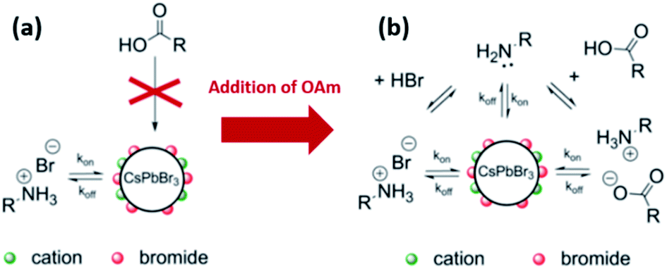 | ||
| Fig. 13 Schematic representations of the dynamic surface stabilization of CsPbBr3 NCs purified with acetone and dispersed in hexane (a) by oleylammonium bromide before the addition of excess OAm and (b) by oleylammonium bromide, oleylammonium oleate and OAm after the addition of excess OAm. The figure is modified with permission from ref. 33. | ||
In the same work, De Roo et al.33 investigated the role of amines by adding excess OAm to the acetone-purified CsPbBr3 NCs. The results showed that OAm is involved in several equilibria (as shown in Fig. 13b): (a) it undergoes acid/base equilibrium reaction with HBr producing OAmH-Br that binds as X-type ligand to the NC surface, (b) it deprotonates OA yielding oleylammonium oleate that is also an X-type ligand with the oleate and OAmH+ binding to the NC surface as an ion pair and (c) it binds in its deprotonated form (OAm) to the surface cations as an L-type ligand. For the last two cases, a ligand exchange occurs between the initial OAmH-Br bound to the surface and the oleylammonium oleate or OAm. This is because the NC surface was fully passivated before the addition of OAm, as discussed before. Measurements based on the different NMR techniques indicated that the oleylammonium oleate ligand was tightly bound to the NC surface.33
Hence, the as-synthesized CsPbBr3 NCs are stabilized by the dynamic interaction with OAmH-Br, which exchanges between its free and bound states. With the addition of amine, oleate binds tightly to the NC surface as an ion pair with the amine and is influenced by the existing acid/base equilibria in the NC solution. Based on these findings, an improved purification protocol of the CsPbBr3 NCs was demonstrated in which both (the acid and the amine) are added with an excess of amine to the NC solution before the precipitation with acetone. This was shown to be beneficial for maintaining the colloidal stability and PLQY with several precipitation/redispersion steps due to the tightly bound oleylammonium oleate.33
The labile nature of alkyl ammonium bonding to the NC surface was also revealed by Pan et al.141 Using 1H NMR and FTIR spectroscopy, it was shown that both alkyl ammonium and carboxylate bind to the surface of CsPbBr3 NCs in toluene or hexane with the alkyl ammonium being more susceptible to detachment from the NC surface during purification and washing with polar solvent. The work was based on replacing Cs2CO3 in the NC synthesis with caesium acetate, which permits using short and saturated alkyl chain acids and bases that have low boiling points. This enables a better assessment of the surface ligands because the overlapping resonances of ODE, alkyl ammonium and oleate in the NMR spectra can then be separated. NMR and FTIR measurements indicated that alkyl ammonium was significantly reduced when the NCs were washed with hexane/acetone, yet it was retained when washing with only hexane. For both washing procedures, it was shown that the carboxylate was not removed. These results were reproducible for a variety of acid–base combinations with different alkyl chain lengths. Based on that, the solvent dependence of the surface ligands was attributed to a weaker ammonium–surface interaction in comparison to carboxylate–surface bonding, which is consistent with the findings of De Roo et al.33 The metal–ligand coordination between the carboxylates and the surface Pb atoms is stronger and more robust towards polar solvent wash than the hydrogen bonding interaction between the surface bromide and the ammonium.141
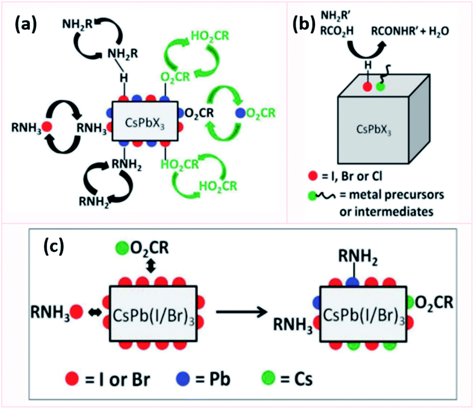 | ||
| Fig. 14 Schematic representation showing in (a) the equilibria of all the ligands involved in the passivation of CsPbX3 NCs, (b) the amide formation by the adsorbed acidic species on the NC surface and in (c) the modification of the surface of CsPb(I/Br)3 NCs upon purification. This figure is modified with permission from ref. 182. | ||
By investigating the surface of CsPbX3 NCs in non-polar solvents using NMR spectroscopy, it was shown that oleate strongly binds to undercoordinated Pb and Cs atoms, OAm weakly binds to surface protons and uncoordinated Pb, and carboxylic acid exchanges with tightly bound oleate. The equilibrium between these species shifts in polar solvents favoring the desorption of oleylammonium halide from the NC surface. During purification with polar antisolvent, the adsorbed acidic species are removed from the NC surface inhibiting the degradation of the organic shell through the formation of amide, which improves the stability of the NCs.182
1H NMR spectroscopy revealed that CsPbCl3 and CsPbBr3 NCs have very similar surface chemistry; while more amides were observed with CsPbI3 NCs. This different behavior is attributed to the soft character of I atoms which favors the interaction with OA. Consequently, OA strongly binds to the surface of CsPbI3 NCs favoring thereby its reaction with OAm to yield the amide. As a result, when exposed to polar solvents or moisture, the surface will undergo structural decomposition as most of the ligands are lost that explains its lower stability compared to CsPbBr3 and CsPbCl3 NCs.182 The instability of the iodide-based perovskite NCs is also attributed to the weaker acid–base interaction between oleylammonium ligand and I− compared to Br− which makes them more susceptible to the loss of ligands during the purification procedure.53
The Cs-enriched surface of CsPbI3 is passivated by the labile Cs-oleate and oleylammonium iodide that compete in both non-polar and polar solvents. Yet, in the case of CsPbBr3 and CsPbCl3, the stronger lead–halide bonds would hamper the dissociation of ammonium in non-polar solvents. In addition, they would allow a stronger interaction of the surface Cs+ with oleate. In the case of the unpurified CsPb(Br/I)3 NCs, an I-rich surface is exposed since it is more difficult for the larger I− to incorporate into the crystal lattice compared to Br−. As a result, these mixed NCs exhibit similar ligation to CsPbI3 showing therefore a large amount of amide and simultaneous presence of labile oleylammonium and Cs-oleate. Purifying these mixed perovskite NCs removes the dangling iodides, thus exposing strongly bound Cs and under-coordinated Pb atoms that are then more efficiently passivated by OA and OAm (Fig. 14c). Hence, these NCs show improved stability after purification.182
5.2 Perovskite NC surface termination
Understanding the surface termination of the NCs is essential as diverse surface terminations are expected to result in different optical and electronic properties.185 The termination of MHP NCs of the general formula ABX3 could be an AX185,186 or BX2 (ref. 36 and 185) rich surface. CsSnI3 terminated with CsI, for example, have shown a higher electron mobility than CsSnI3 terminated with SnI2.187 Combining FTIR, X-ray fluorescence and XPS techniques, Leng et al.188 showed that the surface of MA3Bi2Br9 QDs is Br-rich and that the surface MA+ is replaced with the protonated octylamine ligand, while the OA was found to be bound to Bi ions. The surface of MAPbBr3 NCs was suggested to be surface terminated with MA+ and Br− with the Br:Pb molar ratio being 3.55.58 Similarly, for CsPbBr3 NCs, the Br:Pb ratio was found to be 3.2 (ref. 189) and the surface was enriched with Cs+ and Br− despite the excess PbBr2 used in the synthesis.185 However, another study by Maes et al.190 suggested that the surface Cs+ ions in CsPbBr3 NCs are substituted with OAmH+ and that the surface is partially terminated with PbBr2 since the ratio of Cs to Pb was lower than 1 particularly in small NCs.
Elemental analysis of CsPbX3 NCs via energy dispersive X-ray spectroscopy (EDX) coupled with field emission gun scanning electron microscopy (FEG-SEM) revealed that these NCs have a Cs-enriched surface. The exposed Cs atoms at the NC surface can be then replaced by oleylammonium ions. Hence, the surface of CsPbX3 NCs contains Cs+, oleylammonium ions and halides.182 These results are analogous to the findings of Ravi et al.191 in which an investigation of the CsPbBr3 NCs composition using synchrotron-based XPS revealed that they have a CsBr surface termination. Using 1H NMR measurements and first-principles DFT (density functional theory) calculations, they also showed that the substitution of Cs+ with OAmH+ is energetically feasible and stabilizes the NCs through the formation of hydrogen bonds between –NH3+ group and the Br− ions on the surface. Indeed, as presented in Fig. 15a, there are three H bonds: two H bonds with Br− on the surface and a weaker H bond with Br− in the underneath layer.191 This study also confirmed the outcomes of De Roo's work33 in that OA is not bound to the NC surface and that a constant ratio of OAm/OA or their protonated/deprotonated forms (OAmH+ and oleate) must be maintained to stabilize the NC solution. Indeed, a ratio of OAm:OA = 1:5 resulted in the best PLQY and stability through maintaining this acid/base equilibrium.191
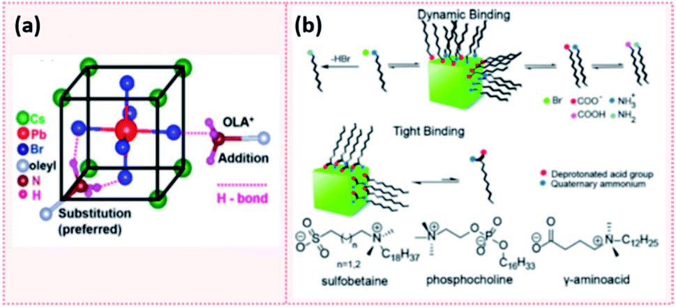 | ||
| Fig. 15 (a) Schematic showing the hydrogen bonding between oleylammonium (OLA+) and Br− on the NC surface. The addition of OLA+ to the surface results in 1 H bond while the substitution of Cs+ with OLA+ which is the more preferred results in 3 H bonds. (b) A scheme showing the dynamic binding of conventional acid and amine ligands and the tight binding of zwitterionic ligands to the perovskite NC surface. The molecular structure of some examples of zwitterionic molecules are also presented. Panels (a) and (b) are taken with permission from ref. 191 and 149. | ||
Additional studies revealed that the presence of Br vacancies on the surface results in under-coordinated Pb atoms that act as trapping sites reducing the PLQY. The addition of excess PbBr2 in a solution of carboxylic acid and amine introduces excess Br− and results in a stronger ligand binding to the surface which improves the surface passivation and thereby the PLQY.192 The under-coordinated Pb2+ ions can be passivated with thiocynate salts (e.g. NH4SCN or NaSCN), for instance, to effectively reduce the nonradiative carrier recombination pathways and leading to near-unity PLQY.9,72
5.3 Purification and isolation of NCs
Research groups have reported different strategies for the purification and isolation of the NCs with a variety of antisolvents and centrifugation parameters based on the composition and morphology of the NCs.57,136,138,162,193–195 Due to the weak and dynamic bonding between the NC surface and the ligands,33,34 the purification process can result in a decline in the photoelectric properties and stability of the NCs and even in some cases loss of their structural integrity due to the desorption of ligands from the surface by the polar solvents used.33 This is especially relevant in the case of iodide-based perovskite NCs which are more susceptible to the loss of ligands during the purification. As a result, the NCs would agglomerate or convert into the photo-inactive phase.53One strategy was demonstrated by the work of De Roo et al.,33 as discussed above, where excess OA and OAm were added for the purification of CsPbBr3 NCs to manipulate the bonding equilibrium between the bound and free ligands. The same purification procedure was adapted by Grisorio et al.182 on CsPbX3 NCs with different halide compositions. The authors showed that the excess OA and OAm during purification was beneficial in preserving the colloidal integrity of the NCs for all halide compositions except for X = I, where the NCs undergo a phase transition as soon as they contact the polar solvent. However, repeating the washing steps resulted in the loss of structural integrity of the NCs due to desorption of ligands. Therefore, the successful purification protocol preserving the stability of CsPbX3 NCs (except CsPbI3) consisted of a single step, where the products from centrifugation were dispersed in hexane with excess OA and OAm added. The NCs are then precipitated with an equal volume of acetone and recollected from a second centrifugation.182
Swarnkar et al.53 proposed a method for purifying CsPbI3 NCs, after examining several low polarity antisolvents. In this method, methyl acetate (MeOAc) was used as an antisolvent to remove the unreacted precursors and isolate CsPbI3 NCs without full removal of surface species; thereby preventing the NCs agglomeration. MeOAc was chosen because it has both the needed polarity for precipitating the NCs and the low solubility preventing the removal of surface ions. The purified NCs, dispersed in hexane, were shown to be stable in the cubic phase for months in ambient conditions compared to only several days for the unpurified NCs. However, an excess of MeOAc caused the destabilization of the NCs and their aggregation due to the removal of the capping ligands.53
Another attempt for purifying perovskite NCs was proposed by Krieg et al.149via employing 3-(N,N-dimethyloctadecylammonio)propanesulfonate as a long chain zwitterionic ligand. Using this ligand, CsPbBr3 NCs were isolated after four precipitation/redispersion rounds with a preserved high PLQY (above 90%). The authors suggested that the use of commercially available zwitterionic molecules (e.g. phosphocholines, γ-amino acids and sulfobetaines) as capping ligands offers two main advantages over the carboxylic acid and amine ligands (Fig. 15b). First, their cationic and anionic groups are not involved in acid–base equilibria. This makes them strongly attached to the NC surface, unlike the highly dynamic bonding between the carboxylate and ammonium moieties with the NC surface caused by the acid–base interactions. Furthermore, the binding of these ligands to the surface is stabilized by chelation.149 Hence, the use of zwitterionic ligands is considered to be a promising strategy for maintaining the colloidal stability during the purification process. This is due to the stronger bonding between the ligands and the NCs, compared to the conventional acid and amine ligands, which inhibits the desorption of the protective ligand shell.
6. Surface manipulation for use of perovskite NC films
Numerous studies on employing MHP NCs in lasers, photodetectors, electroluminescent devices, LEDs and solar cells have been reported.9,13,196,197 For such applications, thin films based on the colloidal NCs have to be fabricated, as suspensions of MHP NC are not practical for use in devices since concentrations and compositions can change with time. Furthermore, for optoelectronic applications it is impractical to make electrical contact to solutions since the faradaic efficiency will be low. Suspended in solution, NCs are dilute and only weakly interacting with each other, which minimizes interfacial reactions and electronic communication between NC. Thin films can be prepared from NC solutions by spin coating, self-assembly and 3D printing for use in large area and flexible devices. Yet, the deposition of these highly luminescent NCs into solid-state films has resulted in a reduction in their PLQY, which negatively affects their use in optoelectronic applications.198 Similarly, the use of porous matrices to grow MHP NCs for applications reduces the optical quality due to aggregation of the host particles and their large size. To successfully employ perovskite NCs in solid state devices, different strategies involving ligands and therefore surface manipulation of have been used, which we will summarize below: (1) ligand exchange, (2) using short, bidentate or branched ligands in the NC synthesis and (3) controlling the ligand density on the NC surface.6.1 Ligand exchange
The long chain ligands that are typically used in the synthesis of MHP NCs are electronically insulating, which impedes charge carrier injection and transport at the interfaces in optoelectronic devices. Furthermore, the labile nature of ligand bonding to the NC surface reduces the stability and the photoluminescence of the NCs during the purification and processing steps. Therefore, for efficiently introducing MHP NCs into optoelectronic devices, these insulating weakly bound long chain molecules must be exchanged with shorter ones that allow better charge transfer or with ligands that have a stronger bonding to the NC surface leading to a better stability. This can be established through ligand exchange in solution or a solid-state ligand exchange.The solution-based ligand exchange is usually done through a two-step process, in which the first step includes the addition of OA to protonate OAm. The protonated OAm reacts with the deprotonated OA forming an acid/base complex that desorbs from the surface enabling the subsequent adsorption of the excess OA on the QD surface. Following this step, a ligand, typically an X-type ligand, is introduced into the NC solution, which fully replaces the OA and remaining OAm on the NC surface.
An example of such a ligand exchange was demonstrated by Pan et al.199 where di-dodecyl dimethyl ammonium bromide (DDAB) ligand was used to replace OA and OAm ligands on the surface of CsPbX3 QDs synthesized by the HI approach (Fig. 16a). This exchange occurs because the Br− ions of DDAB have a stronger affinity than the oleate group to the surface Pb2+ or Cs+ ions. The intermediate step of OA addition was shown to be essential as the direct addition of DDAB to the QDs caused their degradation.199 As observed in Fig. 16b, the ligand exchanged QD solution showed better stability than the untreated one due to the large steric hindrance of the DDA+ ions adsorbed on the QD surface. The application of DDAB-treated CsPbBr3 QDs in LED devices resulted in external quantum efficiency (EQE) of 3%, which was much higher than that of the untreated QDs. This was attributed to the improved charge carrier balance in the QD films treated with this halide-ion pair ligand and the enhanced charge transport due to better crystallinity and less defects in the DDAB-treated QD films.199
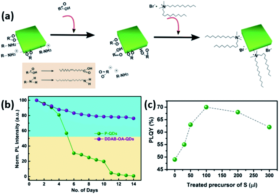 | ||
| Fig. 16 (a) Illustration of the ligand exchange mechanism on CsPbBr3 QDs. (b) The variation of PL intensity with respect to time for unmodified QDs and DDAB-OA treated QDs. Both (a) and (b) are taken with permission from ref. 199. (c) The variation of PLQY values of CsPbBr3 QDs with the amount of the sulfide precursor added. This panel is taken with permission from ref. 200. | ||
A similar hybrid organic–inorganic ion pair, di-dodecyl dimethyl ammonium sulfide (DDAS), was employed to passivate the surface of CsPbBr3 QDs using the same approach.200 Elemental analysis of the samples revealed that both DDA+ and S2− play a role in the passivation. The treatment of the QDs with this sulfur precursor improved the PLQY significantly from 49% to 70% (Fig. 16c). It also endowed the QDs with superior stability in ambient conditions with ∼60% humidity overcoming one of the major issues that hinder the application of MHP NCs. Films based on the treated QDs showed considerable stability under continuous pulsed laser irradiation for 34 hours, which enabled inducing ultrastable amplified spontaneous emission (ASE) in these films.200
By replacing OAm in CsPbBr3 NCs with quaternary ammonium bromide (QAB) ligands of different chain lengths and bulkiness to the OA and OAm, Park et al.147 showed that the NCs surface was better passivated with the less bulky ligands resulting in improved PLQY and stability of the NCs. The chain length did not have a considerable effect on the optical properties of the NCs, yet the charge carrier transport in films based on these NCs was enhanced with the decrease of the ligand chain length. LED devices fabricated using the NC films with optimized ligand chain length and bulkiness achieved high EQE of 9.71% that is 16-fold enhancement compared to OA/OAm-capped CsPbBr3 NCs.147
Ye et al.201 investigated an opposite ligand exchange strategy where two short chain ligands (propionic acid and butylamine) anchored to CsPbBr3 NCs were replaced with longer chain ligands. The ligand exchange was done by adding long chain acid and amine ligands to the NC solution prior to purification. The spincoated NC films became more uniform after the ligand exchange and resulted in improved LED performance. Even though the shorter chain ligands lead to more efficient charge transport properties, the NCs capped with the long chain OA/OAm pair achieved the highest LED performance and best thermal stability because of better defect passivation.201
In addition to the modification of the NC surface, phase transformation, that is usually combined with shape evolution, can occur when adding new ligands to a solution of the pre-synthesized NCs. For instance, the addition of amines to CsPbBr3 NCs leads to a 3D to 0D transformation to Cs4PbBr6 NCs through the extraction of PbBr2 from the 3D structure and its complexation with the amines. The same process occurs on CsPbBr3 NC films exposed to volatile butylamine vapour where they transform into the 0D Cs4PbBr6 NCs and back to the 3D CsPbBr3 upon evaporation of butylamine.202 This 3D to 0D phase transformation was also reported by Liu et al.203via the addition of OAm with various alkyl thiol ligands to CsPbBr3 NCs. Similarly, the ligand-assisted phase transformation of 3D CsPbBr3 NCs into 2D CsPb2Br5 NSs was realized through the addition of DDAB to the NC colloidal solution. The transformation occurred first through exfoliation where Pb2+ complexes with Br− from DDAB forming [PbBr3]− and [Pb2Br5]− complexes followed by a reorganization step to form the CsPb2Br5 NSs.204
Based on that, Suh et al.205 presented a novel way in which a ligand-assisted solubility adjustment step is first applied to the colloidal solution to avoid the loss of ligands from the QD surface. In detail, a ligand solution of 4-phenylbutylamine and benzoic acid in benzene was added to CsPbX3 NC solution followed by precipitating the QDs with acetonitrile and re-dispersing them in benzene. Afterwards, the solid-state ligand exchange was performed on films based on these treated QDs using acid and amine ligands dissolved in octane and benzene co-solvents. Different short-chain acids and amines were tested for the exchange process. The results showed that using aromatic acid/amine ligands in the exchange process is more suitable than the acid/amine ligands based on alkyl chains. This is because a longer chain length is required in the latter case to achieve the same PL intensity as with the aromatic acid/amine ligands. Utilizing the ligand exchanged CsPbX3 QD films as photoemission layers in LEDs resulted in substantial enhancements in their efficiencies compared to their untreated counterparts due to the enhanced photoluminescence and the increased carrier mobility and coupling of lattices via the increased inter-particle connection when employing the short ligands.205
Most of the other studies are based on the use of MeOAc solvent for the solid-state ligand exchange process. This goes back to the work of Swarnkar et al.53 which demonstrated a solid-state ligand exchange process for the use of CsPbI3 QD films as the photoactive layer in solar cell devices. The method is based on dipping the QD films in a saturated solution of lead nitrate Pb(NO3)2 or lead acetate Pb(OAc)2 dissolved in MeOAc. After repeating this step three to five times, the films are washed with MeOAc solution and 100 to 400 nm thick QD films are obtained. The fabricated QD films exhibited efficient electron transport between the dots while retaining phase stability of the QDs. Solar cells based on these were stable during operation and had a high power conversion efficiency (PCE) of 10.77% and an open-circuit voltage (Voc) of 1.23 V. The films were also explored in LED devices where a bright red light was emitted with low turn-on voltage close to its bandgap.53
In 2017, the same research group demonstrated the growth of CsPbI3 QD films via the procedure used by Swarnkar et al.53 but with employing an additional step at the end of film fabrication.206 In this last step, the films were post-treated with AX salts in ethyl acetate (EtOAc), where A is FA, MA or Cs and X is Br or I (Fig. 17). The authors found that the FAI post treatment produced the best overall photovoltaic performance with a PCE value above 13%. Based on FTIR spectra, the authors showed that the native oleate and oleylammonium ligands were removed by the FAI treatment reducing thereby the interparticle spacing between QDs. Furthermore, using time-resolved terahertz spectroscopy (TRTS), it was shown that compared to the untreated film, the FAI-treated QD films exhibited increased charge mobility and similar lifetime. Thus, the mobility-lifetime product, which is proportional to the charge carrier diffusion length, was larger in the FAI-treated film indicating an improved charge extraction.206
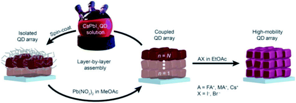 | ||
| Fig. 17 Schematic representation of the deposition process of CsPbI3 QD films followed by AX treatment. The figure is taken with permission from ref. 206. | ||
Wheeler et al.207 explored the surface chemistry of CsPbI3 QD films during this ligand exchange procedure. They showed that the oleate ligand was removed in the first step after washing with MeOAc antisolvent. The saturated solution of Pb(NO3)2 in MeOAc was shown not to directly interact with the QD surface but rather to impact the amount of water that interacts with the surface. The hydrolysis of MeOAc produces acetic acid and methanol as shown in Fig. 18a. Acetic acid protonates the oleate ligands bound to the NC surface and the produced acetate binds to the surface instead (Fig. 18b). XPS, NMR and FTIR spectra proved the selective ligand exchange of oleate with acetate without affecting the composition of CsPbI3 and keeping intact the OAmH+ ligands during the MeOAc washing step. These results suggested that the ligand exchange should occur under controlled relative humidity conditions (11–24%) to obtain smooth high absorbing CsPbI3 QD films. At high humidity conditions, further ester hydrolysis occurs destabilizing the NC surface and transforming CsPbI3 NCs into the yellow phase; whereas at low humidity levels, the NC films are unevenly covered due to solvation of underlying QD layers with subsequent deposition of additional QD layers.207
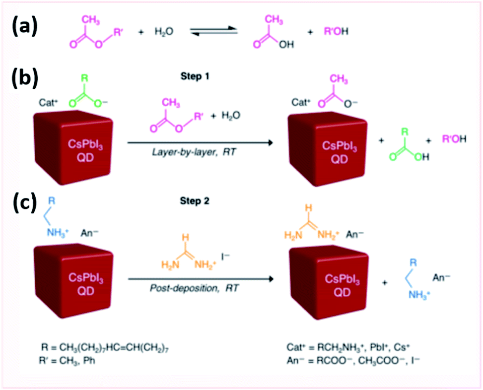 | ||
| Fig. 18 Scheme showing (a) the ester hydrolysis to carboxylic acid and alcohol, (b) the anionic carboxylate ligand exchange and (c) cationic ligand exchange in CsPbI3 QD films. The figure is adapted with permission from ref. 207. | ||
After targeting the oleate ligands with the MeOAc treatment, the exposure of the QD films to FAI was shown to target the loosely bound OAmH+ ligands (Fig. 18c). This resulted in an enhancement in the mobility and inter-dot electronic coupling in FAI-treated films. Indeed, FTIR, X-ray absorption spectroscopy (XAS) and time-of flight secondary ion mass spectroscopy (TOF-SIMS) indicated that the FAI treatment was selective to the surface of the NCs where FA+ exchanges with OAmH+ rather than the Cs+ cations when the films are immersed in the FAI solution for short times. By increasing the time of treatment, the short-circuit current (Jsc) of the solar cells and, consequently, the external quantum efficiency (EQE) increase due to the loss of the insulating ligands that impede the charge transport in the films.207
Later on, this approach was extended for the deposition of layer-by-layer perovskite QD films of controlled composition to fabricate solar cells with an internal heterojunction induced by the compositional changes throughout the films. The heterojunction improved the PCE of the solar cells to 15.74% by enhancing the charge separation at the interfaces and hence improving the photocarrier collection.208
6.2 Modifying the ligands in the NC synthesis
To overcome the limitations imposed by using polar solvents during the postsynthetic and processing steps of MHP NCs, several groups have modified the NC synthesis employing new ligands that can bind more tightly to the NC surface than the typically used ones. This will result in more stable NC films which is required for good performing devices.In one approach, the synthesis of NCs was modified to include only acid ligands. Yassitepe et al.209 reported an amine-free synthesis using tetraocylammonium halides. The obtained OA-capped NCs exhibited improved colloidal stability in polar solvents due to stronger ligand bonding compared to conventional OA/OAm capped NCs. This is because in OA/OAm-capped NCs, a rapid proton exchange occurs between the oleate and amine ligands leading to a dynamic equilibrium between the bound and unbound ligands, as discussed earlier, which limits the stability of the NCs.209 Likewise, Yan et al.210 proposed a ligand modification approach by replacing OA with 2-hexyldecanoic acid (DA) in the HI synthesis of CsPbBr3 QDs as presented in Fig. 19a. DFT calculations showed that the binding energy between this ligand with two short branched chains and the QDs is larger than of OA with the QDs. As a result, DA-capped CsPbBr3 QDs showed improved stability where no aggregation was observed after storing the QD solution in air for more than 70 days.210 Wang et al.211 reported the synthesis of CsPbI3 NCs using TMPPA (bis-(2,2,4-trimethylpentyl)phosphinic acid) instead of OA in the synthesis. The resulting NCs showed improved phase stability compared to the ones synthesized with OA that undergo rapid phase transition to the orthorhombic yellow phase.
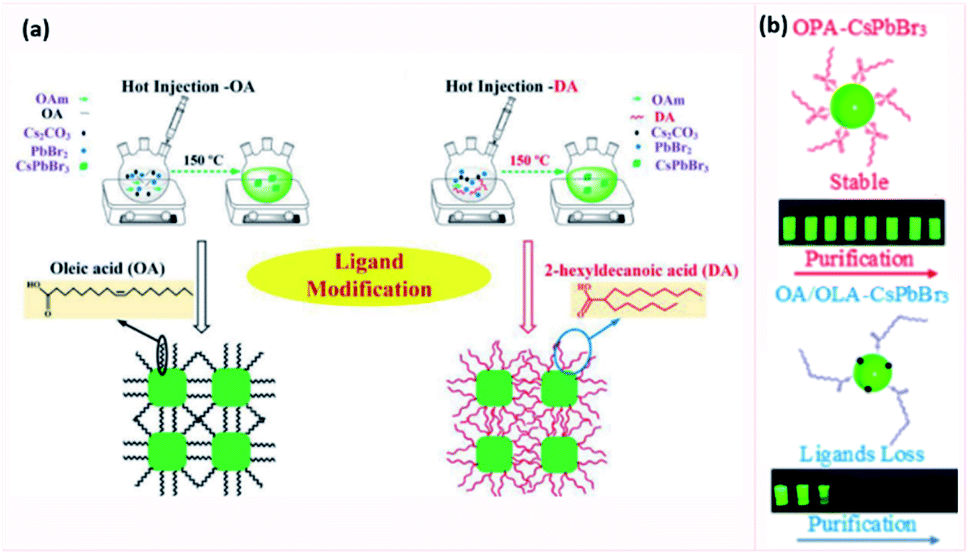 | ||
| Fig. 19 (a) Schematics of the HI synthesis of CsPbBr3 QDs using two different ligands: OA and DA. The OA binding to the QD surface is like building blocks whereas the branched DA ligand binding to the surface is like a web interlaced together. (b) Illustration of the bonding of the surface of purified CsPbBr3 NCs ligated with OPA ligand (in red) or OA/OAm (in blue). The OPA binding stabilizes the NCs and retains the photoluminescence even after 8 purification cycles, whereas OA/OAm ligands are lost during purification resulting in a significant drop in the photoluminescence. Panel (a) and (b) are modified with permission from ref. 210 and 212, respectively. | ||
Another approach is to use zwitterionic ligands to effectively retain the outstanding optoelectronic properties of colloidal NCs and achieve efficient charge carrier transport in NC film. For instance, Motti et al.81 reported the HI synthesis of CsPbBr3 NCs using 3-(N,N-dimethyloctadecylammonio)propanesulfonate and using lecithin. In addition, the authors fabricated films based on NCs capped with a dizwitterionic ligand (3,3′-(hexane-1,6-diylbis(dimethylammoniumdiyl))bis propane-1-sulfonate) through solid state ligand exchange with lecithin.81 Krieg et al.149 reported stable high PLQY for films based on zwitterionic capped-CsPbBr3 NCs. These films exhibited high conductivities and effective charge transport leading to high current densities when employed in LED devices with a peak luminance exceeding 24000 cd m−2 and EQE of 2.5%.149
Multidentate or polymeric ligands, with both amine and carboxylic acid groups, were also used as promising alternatives of OA and OAm ligands since they can bind tightly as a single monolayer.33 In addition, using branched ligands such as APTES, POSS, OPA (octylphosphonic acid), TOP (trioctylphosphine) and TOPO (trioctylphosphine oxide) was shown to improve the NCs stability through the strong steric effect and strong binding to the NC surface.73,128 For example, OPA-capped CsPbX3 NCs, showed a large enhancement in the stability compared to OA/OAm-capped NCs where the PLQY were preserved after eight purification cycles with hexane/MeOAc (Fig. 19b). This was attributed to the strong interaction between Pb and OPA.212 Yang et al.213 reported the synthesis of CsPbBr3 QDs using dodecylbenzene sulfonic acid (DBSA) as a ligand. This ligand was used because of the strong bonding of the sulfonate group with the surface Pb ions on one hand. On another hand, it was used as a “Br-equivalent” ligand where it acts in a similar way to the Br− ions coordinating strongly to Pb ions in the perovskite lattice. This reduces the Br vacancies which act as trapping sites lowering the PLQY. As a result, the DBSA-capped QDs exhibited PLQY above 90% even after eight purification cycles and storage for more than five months.213
A two-step surface engineering method was carried out by Li et al.214 in which a short π-conjugation ligand phenethylamine (PEA) was used. In this process, OAm was partially replaced with PEA in the synthesis of CsPbX3 QDs followed by solid-state ligand exchange on the QD films using PEAX (X being Br or I). The resulting films showed a remarkable improvement in the charge carrier transport and a reduction in the trap states compared to untreated QD film. An EQE of 14.08% was achieved in LED devices based on CsPbI3 NCs treated with PEA ligand.214
6.3 Controlling ligand density on NC surface
Besides the type of ligands used, their density on the NC surface affects the optoelectronic properties of the NC films. Insufficient ligand density lowers the PLQY and reduces the stability of the QD suspension, whereas an excess of ligands results in poor carrier injection and transport in QD films.For an effective control of surface ligands of FAPbI3 QDs, Xue et al.215 classified the solvents that can be used in the surface treatment into three grades based on their polarity. Grade I constitutes of highly polar solvents that can break the ionic bonds in the QDs. Grade III consists of solvents with very low polarity that they could not break the bonding of ligands to the QD surface. Therefore, grade II antisolvents with moderate polarity are considered the best choice for effective surface treatment where the ligand density on the QD surface is dropped while preserving the structure of FAPbI3 QDs. Based on that, this group presented a surface treatment procedure consisting of two cycles in the colloidal solution followed by one treatment cycle carried out during the QD-film fabrication. In the first cycle, 2-pentanol was used as a grade II antisolvent to reduce the ligand density. Then, a lower polarity solvent was used in the second cycle to keep the structural integrity of FAPbI3 QDs and resulting in an efficient removal of ligands after two cycles. The last cycle was performed by rinsing the films with EtOAc to improve the coupling between QDs. Photovoltaic devices fabricated based on these three-cycle treated FAPbI3 QDs achieved a PCE of 8.38% with superior stability under ambient conditions. The improved EQE of the devices with the treatment cycles reflected an improved charge collection due to the decrease of ligand density and subsequent improvement in the inter-dot coupling.215
In another study, it was shown that after exploring a series of solvents the treatment of CsPbBr3 QDs using a mixed hexane/EtOAc solvent enabled the control of ligand density on the NCs surface.216 As a result of this treatment, stable QD inks were prepared with preserved high stability enabling the growth of uniform QD films exhibiting a balance between surface passivation and carrier injection. LEDs based on these treated-QD films showed a remarkable EQE of 6.27% that corresponds to 50-fold enhancement with respect to QDs treated with one cycle of acetone. This outstanding efficiency of CsPbBr3 QD LEDs among the inorganic perovskite LEDs suggests that the performance of these devices can be improved, not only through surface ligand exchange, but also through controlling the surface ligand density.216
Annealing is another strategy that can be used to remove long chain ligands and increase the inter-particle coupling. By varying the annealing temperature, the coupling between NCs can be controlled. A post-annealing procedure of CsPbBr3 NS films was shown to partially remove the organic ligands improving thereby the coupling between NSs, the charge transfer and the produced photocurrent.217
However, to date, there is no report of a clear strategy of controlling effectively and precisely the ligand density in perovskite NCs. The optimal amount of the different types of ligands needed for both the stability and application of the NCs must be also explored.
7. Conclusion and outlook
Perovskite NCs exhibit promising properties such as optical tunability through size and composition modification, defect tolerance, high PLQY and ease of synthesis. Different approaches have been used to synthesize MHP NCs, most of which rely on capping ligands. The effect of ligands on the properties of NCs during their synthesis, purification and application is summarized in Fig. 20.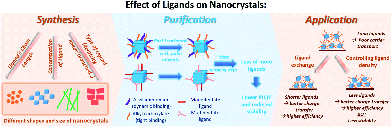 | ||
| Fig. 20 A schematic showing the role of ligands during the synthesis, purification and application of perovskite NCs. | ||
It was shown that both acidic (carboxylic acids) and basic (amines) ligands are essential in stabilizing the NCs and determining their morphological and optical properties. The size, shape and structure of the NCs depend on the type of used ligand, the length and bulkiness of its hydrocarbon chain, and its concentration with respect to the precursors, where the size generally decreases with higher ligand concentration or longer alkyl chain of the ligand.
Surface studies on perovskite NCs have shown that the NC–ligand interaction is generally weak and dynamic which leads to the desorption of the ligands upon purification of the NCs. As a consequence, the stability and photoelectric properties of the NCs are reduced after purification. Another challenge is that the commonly used ligands in the NC synthesis are long alkyl chain carboxylic acids and amines. These insulating ligands hinder the charge transport throughout the NC-based films and increase the barrier for carrier injection at the interfaces in optoelectronic devices based on these NCs.
So far, research efforts have been directed to face these challenges by considering several strategies including: (1) a careful choice of the antisolvent used in the purification of the NCs and in the NC film deposition, (2) ligand exchange to replace the insulating and weak-binding ligands with ligands that enable a stronger bonding to the NC surface and better charge transport in the NC films, and (3) ligand management by introducing new ligands in the NCs synthesis or controlling the ligands density on the NC surface to meet both demands: stable NCs and efficient charge transport in NC films.
Besides these aspects that have been covered in the review, this field is open for more exhaustive studies. Most of the surface investigations are carried out using inorganic CsPbX3 NCs, which are not necessarily valid for other materials, while investigations related to organic LHP NCs and lead-free MHP NCs are still missing. Hence, a logical development in this direction would be to extend these studies to other MHP NCs (organic LHP and lead-free MHP NCs) to achieve a deeper understanding of the surface termination and ligation in MHP NCs. Furthermore, there is still plenty of room to explore new ligands (such as inorganic ligands) aiming to attain a better stabilization of the NCs and a more efficient application in devices. These investigations will be possible due to the availability and advancements in the characterization techniques (e.g. NMR) and theoretical calculations.
Another research pillar is to unveil the role of ligands in the early stages of NC synthesis and have a deeper insight into the nucleation and growth of NCs. This would enable a better control of the kinetics and shape evolution during the NC synthesis. Microfluidic methods had been used to follow the early formation of LHP NCs and enable a fast screening of reaction conditions.60,167,218 This strategy can be elaborated to investigate other MHP NCs and to monitor a broader range of reaction conditions including the use of new ligands and solvents.
One of the main research frontiers is to find alternative deposition techniques for fabricating stable NC thin films that can be directly applied in devices. MHP NC films are typically deposited by spincoating since this allows a uniform film coverage. However, to obtain films that are sufficiently thick for applications, several cycles of NC deposition and ligand exchange and washing are needed. Besides being time consuming, with every deposition cycle the used antisolvents can wash off some the previously deposited NCs, which makes it tricky to control the thickness of the films and to obtain reproducible devices afterwards. Therefore, finding methods which enable the growth of thick and uniform films based on MHP NCs remains an open issue that must be resolved in the upcoming years. More studies should also investigate how to improve the packing between NCs to enhance the charge transport in films. This can be achieved by thorough investigations of different ligands and processing steps (e.g. annealing) during the NC film fabrication. Moreover, investigating the interface between the NC film and the different layers in optoelectronic devices (such as electron transport layers and hole transport layers) will be essential to eliminate possible charge losses and to obtain devices with outperforming efficiencies and stability.
Other issues that still need to be understood and can be used to outline the future guidelines of research in this field include: optimizing the post-treatment steps for every system including the purification and the ligand exchange by using less aggressive procedures, exploring different combinations of A-, B-site cations and halides that can replace LHP NCs and outperform them in terms of stability and optoelectronic properties and investigating the effect of ligation on the excitonic properties of NCs. Also, understanding ligation in mixed perovskite NC systems would be interesting for future studies as it was shown that surface ligands play a critical role in the A-site cation exchange of LHP QDs.219
Furthermore, as discussed earlier, the issue of stability remains a main obstacle for the efficient utilization of MHP NCs. In this respect, incorporating MHP NCs in heterostructures to protect them against the harsh environmental conditions is one strategy that has been explored. However, a full understanding of the interface of the perovskite with other materials in these heterostructures and the efficiency of such structures in stabilizing the NCs on long term basis remains scarcely studied. In addition, the synthesis of a core/shell nanostructure, which allows a complete protection of the perovskite NC is still challenging and is a triggering future research area.
By understanding the surface chemistry and managing the ligand stabilization of perovskite nanocrystals, these materials may find eventual uses in solar energy and energy efficient lighting.
Author contributions
Conceptualization: all authors. Visualization and writing – original draft: Fatima Haydous. Supervision, funding acquisition and project administration: James M. Gardner and Ute B. Cappel. Writing – review & editing: all authors.Conflicts of interest
There are no conflicts to declare.Acknowledgements
We acknowledge research funding from the Swedish Research Council (Grant No. VR 2018-04125), the Olle Engkvist Foundation and the Göran Gustafsson Foundation. James Gardner gratefully acknowledges support from the Swedish Government through the research initiative STandUP for ENERGY.References
- W. R. Tilluck, A. L. Morris, J. K. Gurchiek, A. D. Evans and P. G. Van Patten, RSC Adv., 2016, 6, 81780–81788 RSC.
- P. Moroz, L. Royo Romero and M. Zamkov, Chem. Commun., 2019, 55, 3033–3048 RSC.
- H. Huang, A. S. Susha, S. V. Kershaw, T. F. Hung and A. L. Rogach, Adv. Sci., 2015, 2, 1500194 CrossRef PubMed.
- P.-J. Lu, S.-C. Huang, Y.-P. Chen, L.-C. Chiueh and D. Y.-C. Shih, J. Food Drug Anal., 2015, 23, 587–594 CrossRef CAS PubMed.
- L. Mu and R. L. Sprando, Pharm. Res., 2010, 27, 1746–1749 CrossRef CAS PubMed.
- J. Zhou, Y. Liu, J. Tang and W. Tang, Mater. Today, 2017, 20, 360–376 CrossRef CAS.
- O. V. Salata, J. Nanobiotechnol., 2004, 2, 3 CrossRef PubMed.
- S. Priyadarsini, S. Mohanty, S. Mukherjee, S. Basu and M. Mishra, J. Nanostruct. Chem., 2018, 8, 123–137 CrossRef CAS.
- H.-C. Wang, Z. Bao, H.-Y. Tsai, A.-C. Tang and R.-S. Liu, Small, 2018, 14, 1702433 CrossRef PubMed.
- Y. Zhang, R. Sun, X. Ou, K. Fu, Q. Chen, Y. Ding, L.-J. Xu, L. Liu, Y. Han, A. V. Malko, X. Liu, H. Yang, O. M. Bakr, H. Liu and O. F. Mohammed, ACS Nano, 2019, 13, 2520–2525 CrossRef CAS PubMed.
- S.-W. Dai, B.-W. Hsu, C.-Y. Chen, C.-A. Lee, H.-Y. Liu, H.-F. Wang, Y.-C. Huang, T.-L. Wu, A. Manikandan, R.-M. Ho, C.-S. Tsao, C.-H. Cheng, Y.-L. Chueh and H.-W. Lin, Adv. Mater., 2018, 30, 1705532 CrossRef PubMed.
- S. H. Im, H.-j. Kim, S. W. Kim, S.-W. Kim and S. I. Seok, Energy Environ. Sci., 2011, 4, 4181–4186 RSC.
- M. V. Kovalenko, L. Protesescu and M. I. Bodnarchuk, Science, 2017, 358, 745–750 CrossRef CAS PubMed.
- J. Shamsi, A. S. Urban, M. Imran, L. De Trizio and L. Manna, Chem. Rev., 2019, 119, 3296–3348 CrossRef CAS PubMed.
- M. M. Lee, J. Teuscher, T. Miyasaka, T. N. Murakami and H. J. Snaith, Science, 2012, 338, 643–647 CrossRef CAS PubMed.
- P. Fu, Q. Shan, Y. Shang, J. Song, H. Zeng, Z. Ning and J. Gong, Sci. Bull., 2017, 62, 369–380 CrossRef CAS.
- NREL, Photovoltaic Research, Best Research-Cell Efficiency Chart, accessed 19 July 2020 Search PubMed.
- J. Yu, G. Liu, C. Chen, Y. Li, M. Xu, T. Wang, G. Zhao and L. Zhang, J. Mater. Chem. C, 2020, 8, 6326–6341 RSC.
- C.-Y. Chang, A. N. Solodukhin, S.-Y. Liao, K. P. O. Mahesh, C.-L. Hsu, S. A. Ponomarenko, Y. N. Luponosov and Y.-C. Chao, J. Mater. Chem. C, 2019, 7, 8634–8642 RSC.
- C. H. A. Li, Z. Zhou, P. Vashishtha and J. E. Halpert, Chem. Mater., 2019, 31, 6003–6032 CrossRef CAS.
- J. Miao and F. Zhang, J. Mater. Chem. C, 2019, 7, 1741–1791 RSC.
- M. M. Stylianakis, T. Maksudov, A. Panagiotopoulos, G. Kakavelakis and K. Petridis, Materials, 2019, 12, 859 CrossRef CAS PubMed.
- Z. Wei and J. Xing, J. Phys. Chem. Lett., 2019, 10, 3035–3042 CrossRef CAS PubMed.
- C. Xie, C.-K. Liu, H.-L. Loi and F. Yan, Adv. Funct. Mater., 2020, 30, 1903907 CrossRef CAS.
- T. T. Ngo and I. Mora-Seró, J. Phys. Chem. Lett., 2019, 10, 1099–1108 CrossRef CAS PubMed.
- M. Leng, Y. Yang, K. Zeng, Z. Chen, Z. Tan, S. Li, J. Li, B. Xu, D. Li, M. P. Hautzinger, Y. Fu, T. Zhai, L. Xu, G. Niu, S. Jin and J. Tang, Adv. Funct. Mater., 2018, 28, 1704446 CrossRef.
- H. Huang, M. I. Bodnarchuk, S. V. Kershaw, M. V. Kovalenko and A. L. Rogach, ACS Energy Lett., 2017, 2, 2071–2083 CrossRef CAS PubMed.
- Q. A. Akkerman, G. Rainò, M. V. Kovalenko and L. Manna, Nat. Mater., 2018, 17, 394–405 CrossRef CAS PubMed.
- W. J. Mir, T. Sheikh, H. Arfin, Z. Xia and A. Nag, NPG Asia Mater., 2020, 12, 9 CrossRef CAS.
- A. Rubino, L. Caliò, A. García-Bennett, M. E. Calvo and H. Míguez, Adv. Opt. Mater., 2020, 8, 1901868 CrossRef CAS.
- Q. Fan, G. V. Biesold-McGee, J. Ma, Q. Xu, S. Pan, J. Peng and Z. Lin, Angew. Chem., Int. Ed., 2020, 59, 1030–1046 CrossRef CAS PubMed.
- M. Green, J. Organomet. Chem., 1995, 500, 127–148 CrossRef CAS.
- J. De Roo, M. Ibáñez, P. Geiregat, G. Nedelcu, W. Walravens, J. Maes, J. C. Martins, I. Van Driessche, M. V. Kovalenko and Z. Hens, ACS Nano, 2016, 10, 2071–2081 CrossRef CAS PubMed.
- N. Kirkwood, J. O. V. Monchen, R. W. Crisp, G. Grimaldi, H. A. C. Bergstein, I. du Fossé, W. van der Stam, I. Infante and A. J. Houtepen, J. Am. Chem. Soc., 2018, 140, 15712–15723 CrossRef CAS PubMed.
- K. Xu, C. C. Lin, X. Xie and A. Meijerink, Chem. Mater., 2017, 29, 4265–4272 CrossRef CAS PubMed.
- J. Pan, Y. Shang, J. Yin, M. De Bastiani, W. Peng, I. Dursun, L. Sinatra, A. M. El-Zohry, M. N. Hedhili, A.-H. Emwas, O. F. Mohammed, Z. Ning and O. M. Bakr, J. Am. Chem. Soc., 2018, 140, 562–565 CrossRef CAS PubMed.
- H. Takeuchi, B. Omogo and C. D. Heyes, Nano Lett., 2013, 13, 4746–4752 CrossRef CAS PubMed.
- B. Lv, Y. Xu, D. Wu and Y. Sun, Chem. Commun., 2011, 47, 967–969 RSC.
- A. Klein, A. Kaiser, W. Wielandt, F. Belaj, E. Wendel, H. Bertagnolli and S. Záliš, Inorg. Chem., 2008, 47, 11324–11333 CrossRef CAS PubMed.
- A. Dehno Khalaji, M. Weil, H. Hadadzadeh and M. Daryanavard, Inorg. Chim. Acta, 2009, 362, 4837–4842 CrossRef CAS.
- B. N. Sivasankar and S. Govindarajan, Synthesis and Reactivity in Inorganic and Metal-Organic Chemistry, 1995, 25, pp. 31–43 Search PubMed.
- S. Govindarajan, K. C. Patil, H. Manohar and P.-E. Werner, J. Chem. Soc., Dalton Trans., 1986, 119–123, 10.1039/DT9860000119.
- E. Waldhör, W. Kaim, J. A. Olabe, L. D. Slep and J. Fiedler, Inorg. Chem., 1997, 36, 2969–2974 CrossRef PubMed.
- A. Nag, M. V. Kovalenko, J.-S. Lee, W. Liu, B. Spokoyny and D. V. Talapin, J. Am. Chem. Soc., 2011, 133, 10612–10620 CrossRef CAS PubMed.
- M. Mittal, A. Jana, S. Sarkar, P. Mahadevan and S. Sapra, J. Phys. Chem. Lett., 2016, 7, 3270–3277 CrossRef CAS PubMed.
- D. Chen, X. Chen, Z. Wan and G. Fang, ACS Appl. Mater. Interfaces, 2017, 9, 20671–20678 CrossRef CAS PubMed.
- B. Xu, W. Wang, X. Zhang, W. Cao, D. Wu, S. Liu, H. Dai, S. Chen, K. Wang and X. Sun, J. Mater. Chem. C, 2018, 6, 668 RSC.
- L. Protesescu, S. Yakunin, S. Kumar, J. Bär, F. Bertolotti, N. Masciocchi, A. Guagliardi, M. Grotevent, I. Shorubalko, M. I. Bodnarchuk, C.-J. Shih and M. V. Kovalenko, ACS Nano, 2017, 11, 3119–3134 CrossRef CAS PubMed.
- Y.-F. Li, J. Feng and H.-B. Sun, Nanoscale, 2019, 11, 19119–19139 RSC.
- J. Deng, J. Li, Z. Yang and M. Wang, J. Mater. Chem. C, 2019, 7, 12415–12440 RSC.
- W. Travis, E. N. K. Glover, H. Bronstein, D. O. Scanlon and R. G. Palgrave, Chem. Sci., 2016, 7, 4548–4556 RSC.
- Y. Dong, Y. Zhao, S. Zhang, Y. Dai, L. Liu, Y. Li and Q. J. Chen, J. Mater. Chem. A, 2018, 6, 21729–21746 RSC.
- A. Swarnkar, A. R. Marshall, E. M. Sanehira, B. D. Chernomordik, D. T. Moore, J. A. Christians, T. Chakrabarti and J. M. Luther, Science, 2016, 354, 92–95 CrossRef CAS PubMed.
- C. C. Stoumpos, C. D. Malliakas and M. G. Kanatzidis, Inorg. Chem., 2013, 52, 9019–9038 CrossRef CAS PubMed.
- K. Hong, Q. V. Le, S. Y. Kim and H. W. Jang, J. Mater. Chem. C, 2018, 6, 2189–2209 RSC.
- M. I. Saidaminov, O. F. Mohammed and O. M. Bakr, ACS Energy Lett., 2017, 2, 889–896 CrossRef CAS.
- L. Protesescu, S. Yakunin, M. I. Bodnarchuk, F. Krieg, R. Caputo, C. H. Hendon, R. X. Yang, A. Walsh and M. V. Kovalenko, Nano Lett., 2015, 15, 3692–3696 CrossRef CAS PubMed.
- F. Zhang, H. Zhong, C. Chen, X.-g. Wu, X. Hu, H. Huang, J. Han, B. Zou and Y. Dong, ACS Nano, 2015, 9, 4533–4542 CrossRef CAS PubMed.
- L. Protesescu, S. Yakunin, M. I. Bodnarchuk, F. Bertolotti, N. Masciocchi, A. Guagliardi and M. V. Kovalenko, J. Am. Chem. Soc., 2016, 138, 14202–14205 CrossRef CAS PubMed.
- I. Lignos, L. Protesescu, D. B. Emiroglu, R. Maceiczyk, S. Schneider, M. V. Kovalenko and A. J. deMello, Nano Lett., 2018, 18, 1246–1252 CrossRef CAS PubMed.
- D. N. Minh, J. Kim, J. Hyon, J. H. Sim, H. H. Sowlih, C. Seo, J. Nam, S. Eom, S. Suk, S. Lee, E. Kim and Y. Kang, Chem. Mater., 2017, 29, 5713–5719 CrossRef CAS.
- T. Umebayashi, K. Asai, T. Kondo and A. Nakao, Phys. Rev. B, 2003, 67, 155405 CrossRef.
- V. K. Ravi, G. B. Markad and A. Nag, ACS Energy Lett., 2016, 1, 665–671 CrossRef CAS.
- T. C. Jellicoe, J. M. Richter, H. F. J. Glass, M. Tabachnyk, R. Brady, S. E. Dutton, A. Rao, R. H. Friend, D. Credgington, N. C. Greenham and M. L. Böhm, J. Am. Chem. Soc., 2016, 138, 2941–2944 CrossRef CAS PubMed.
- P. Arunkumar, K. H. Gil, S. Won, S. Unithrattil, Y. H. Kim, H. J. Kim and W. B. Im, J. Phys. Chem. Lett., 2017, 8, 4161–4166 CrossRef CAS PubMed.
- G. E. Eperon, S. D. Stranks, C. Menelaou, M. B. Johnston, L. M. Herz and H. J. Snaith, Energy Environ. Sci., 2014, 7, 982–988 RSC.
- S. Meloni, G. Palermo, N. Ashari-Astani, M. Grätzel and U. Rothlisberger, J. Mater. Chem. A, 2016, 4, 15997–16002 RSC.
- Y. Tong, E. Bladt, M. F. Aygüler, A. Manzi, K. Z. Milowska, V. A. Hintermayr, P. Docampo, S. Bals, A. S. Urban, L. Polavarapu and J. Feldmann, Angew. Chem., Int. Ed., 2016, 55, 13887–13892 CrossRef CAS PubMed.
- S. Gonzalez-Carrero, L. Francés-Soriano, M. González-Béjar, S. Agouram, R. E. Galian and J. Pérez-Prieto, Small, 2016, 12, 5245–5250 CrossRef CAS PubMed.
- M. Imran, V. Caligiuri, M. Wang, L. Goldoni, M. Prato, R. Krahne, L. De Trizio and L. Manna, J. Am. Chem. Soc., 2018, 140, 2656–2664 CrossRef CAS PubMed.
- I. Levchuk, A. Osvet, X. Tang, M. Brandl, J. D. Perea, F. Hoegl, G. J. Matt, R. Hock, M. Batentschuk and C. J. Brabec, Nano Lett., 2017, 17, 2765–2770 CrossRef CAS PubMed.
- B. A. Koscher, J. K. Swabeck, N. D. Bronstein and A. P. Alivisatos, J. Am. Chem. Soc., 2017, 139, 6566–6569 CrossRef CAS PubMed.
- F. Liu, Y. Zhang, C. Ding, S. Kobayashi, T. Izuishi, N. Nakazawa, T. Toyoda, T. Ohta, S. Hayase, T. Minemoto, K. Yoshino, S. Dai and Q. Shen, ACS Nano, 2017, 11, 10373–10383 CrossRef CAS PubMed.
- Y. Peter and M. Cardona, Fundamentals of Semiconductors: Physics and Materials Properties, Springer Science & Business Media, 2010 Search PubMed.
- K. Tanaka, T. Takahashi, T. Ban, T. Kondo, K. Uchida and N. Miura, Solid State Commun., 2003, 127, 619–623 CrossRef CAS.
- J. Shamsi, A. S. Urban, M. Imran, L. De Trizio and L. Manna, Chem. Rev., 2019, 119, 3296–3348 CrossRef CAS PubMed.
- J. Even, L. Pedesseau and C. Katan, J. Phys. Chem. C, 2014, 118, 11566–11572 CrossRef CAS.
- M. Saba, M. Cadelano, D. Marongiu, F. Chen, V. Sarritzu, N. Sestu, C. Figus, M. Aresti, R. Piras, A. Geddo Lehmann, C. Cannas, A. Musinu, F. Quochi, A. Mura and G. Bongiovanni, Nat. Commun., 2014, 5, 5049 CrossRef CAS PubMed.
- E. Menéndez-Proupin, P. Palacios, P. Wahnón and J. C. Conesa, Phys. Rev. B: Condens. Matter Mater. Phys., 2014, 90, 045207 CrossRef.
- J. Li, L. Luo, H. Huang, C. Ma, Z. Ye, J. Zeng and H. He, J. Phys. Chem. Lett., 2017, 8, 1161–1168 CrossRef CAS PubMed.
- S. G. Motti, F. Krieg, A. J. Ramadan, J. B. Patel, H. J. Snaith, M. V. Kovalenko, M. B. Johnston and L. M. Herz, Adv. Funct. Mater., 2020, 30, 1909904 CrossRef CAS.
- Y. Shynkarenko, M. I. Bodnarchuk, C. Bernasconi, Y. Berezovska, V. Verteletskyi, S. T. Ochsenbein and M. V. Kovalenko, ACS Energy Lett., 2019, 4, 2703–2711 CrossRef CAS PubMed.
- W.-J. Yin, T. Shi and Y. Yan, Appl. Phys. Lett., 2014, 104, 063903 CrossRef.
- J. M. Ball and A. Petrozza, Nat. Energy, 2016, 1, 16149 CrossRef CAS.
- S. Ten Brinck, F. Zaccaria and I. Infante, ACS Energy Lett., 2019, 4, 2739–2747 CrossRef CAS.
- J. Kang and L.-W. Wang, J. Phys. Chem. Lett., 2017, 8, 489–493 CrossRef CAS PubMed.
- Y. Guo, Q. Wang and W. A. Saidi, J. Phys. Chem. C, 2017, 121, 1715–1722 CrossRef CAS.
- L. C. Schmidt, A. Pertegás, S. González-Carrero, O. Malinkiewicz, S. Agouram, G. Mínguez Espallargas, H. J. Bolink, R. E. Galian and J. Pérez-Prieto, J. Am. Chem. Soc., 2014, 136, 850–853 CrossRef CAS PubMed.
- L. Yuan, R. Patterson, X. Wen, Z. Zhang, G. Conibeer and S. Huang, J. Colloid Interface Sci., 2017, 504, 586–592 CrossRef CAS PubMed.
- T. Leijtens, G. E. Eperon, N. K. Noel, S. N. Habisreutinger, A. Petrozza and H. J. Snaith, Adv. Energy Mater., 2015, 5, 1500963 CrossRef.
- T. A. Berhe, W.-N. Su, C.-H. Chen, C.-J. Pan, J.-H. Cheng, H.-M. Chen, M.-C. Tsai, L.-Y. Chen, A. A. Dubale and B.-J. Hwang, Energy Environ. Sci., 2016, 9, 323–356 RSC.
- N. Aristidou, C. Eames, I. Sanchez-Molina, X. Bu, J. Kosco, M. S. Islam and S. A. Haque, Nat. Commun., 2017, 8, 15218 CrossRef PubMed.
- S. Hou, Y. Guo, Y. Tang and Q. Quan, ACS Appl. Mater. Interfaces, 2017, 9, 18417–18422 CrossRef CAS.
- M. Meyns, M. Perálvarez, A. Heuer-Jungemann, W. Hertog, M. Ibáñez, R. Nafria, A. Genç, J. Arbiol, M. V. Kovalenko, J. Carreras, A. Cabot and A. G. Kanaras, ACS Appl. Mater. Interfaces, 2016, 8, 19579–19586 CrossRef CAS.
- S. N. Raja, Y. Bekenstein, M. A. Koc, S. Fischer, D. Zhang, L. Lin, R. O. Ritchie, P. Yang and A. P. Alivisatos, ACS Appl. Mater. Interfaces, 2016, 8, 35523–35533 CrossRef CAS PubMed.
- A. N. Aleshin, I. P. Shcherbakov, E. V. Gushchina, L. B. Matyushkin and V. A. Moshnikov, Org. Electron., 2017, 50, 213–219 CrossRef CAS.
- J. He, H. Chen, H. Chen, Y. Wang, S.-T. Wu and Y. Dong, Opt. Express, 2017, 25, 12915–12925 CrossRef CAS PubMed.
- K. Ma, X.-Y. Du, Y.-W. Zhang and S. Chen, J. Mater. Chem. C, 2017, 5, 9398–9404 RSC.
- L. Xi, C. B. Boothroyd, T. Salim, S. Borghardt, Y. M. Lam and B. E. Kardynał, J. Mater. Chem. C, 2017, 5, 7207–7214 RSC.
- H. An, W. K. Kim, C. Wu and T. W. Kim, Org. Electron., 2018, 56, 41–45 CrossRef CAS.
- X. Li, Z. Xue, D. Luo, C. Huang, L. Liu, X. Qiao, C. Liu, Q. Song, C. Yan, Y. Li and T. Wang, Sci. China Mater., 2018, 61, 363–370 CrossRef CAS.
- Y. Xin, H. Zhao and J. Zhang, ACS Appl. Mater. Interfaces, 2018, 10, 4971–4980 CrossRef CAS PubMed.
- S. Yang, F. Zhang, J. Tai, Y. Li, Y. Yang, H. Wang, J. Zhang, Z. Xie, B. Xu, H. Zhong, K. Liu and B. Yang, Nanoscale, 2018, 10, 5820–5826 RSC.
- M. Zhang, M. Wang, Z. Yang, J. Li and H. Qiu, J. Alloys Compd., 2018, 748, 537–545 CrossRef CAS.
- H. Zhang, X. Wang, Q. Liao, Z. Xu, H. Li, L. Zheng and H. Fu, Adv. Funct. Mater., 2017, 27, 1604382 CrossRef.
- Q. Wang, Z. Jin, D. Chen, D. Bai, H. Bian, J. Sun, G. Zhu, G. Wang and S. Liu, Adv. Energy Mater., 2018, 8, 1800007 CrossRef.
- Z. Tan, Y. Wu, H. Hong, J. Yin, J. Zhang, L. Lin, M. Wang, X. Sun, L. Sun, Y. Huang, K. Liu, Z. Liu and H. Peng, J. Am. Chem. Soc., 2016, 138, 16612–16615 CrossRef CAS PubMed.
- D.-H. Kwak, D.-H. Lim, H.-S. Ra, P. Ramasamy and J.-S. Lee, RSC Adv., 2016, 6, 65252–65256 RSC.
- A. Pan, M. J. Jurow, F. Qiu, J. Yang, B. Ren, J. J. Urban, L. He and Y. Liu, Nano Lett., 2017, 17, 6759–6765 CrossRef CAS PubMed.
- Y.-F. Xu, M.-Z. Yang, B.-X. Chen, X.-D. Wang, H.-Y. Chen, D.-B. Kuang and C.-Y. Su, J. Am. Chem. Soc., 2017, 139, 5660–5663 CrossRef CAS PubMed.
- Q. Wang, L. Tao, X. Jiang, M. Wang and Y. Shen, Appl. Surf. Sci., 2019, 465, 607–613 CrossRef CAS.
- J.-S. Chen, T. L. Doane, M. Li, H. Zang, M. M. Maye and M. Cotlet, Part. Part. Syst. Charact., 2018, 35, 1700310 CrossRef.
- H. Huang, J. Li, Y. Yi, J. Wang, Y. Kang, P. K. Chu, H. C. Ong and X.-F. Yu, Chem. Commun., 2018, 54, 2365–2368 RSC.
- H. Li, X. Zheng, Y. Liu, Z. Zhang and T. Jiang, Nanoscale, 2018, 10, 1650–1659 RSC.
- S. Muduli, P. Pandey, G. Devatha, R. Babar, T. M, D. C. Kothari, M. Kabir, P. P. Pillai and S. Ogale, Angew. Chem., 2018, 57, 7682–7686 CrossRef CAS PubMed.
- Y. Chen, M. Yu, S. Ye, J. Song and J. Qu, Nanoscale, 2018, 10, 6704–6711 RSC.
- X. Di, J. Jiang, Z. Hu, L. Zhou, P. Li, S. Liu, W. Xiang and X. Liang, Dyes Pigm., 2017, 146, 361–367 CrossRef CAS.
- L. Xu, J. Chen, J. Song, J. Li, J. Xue, Y. Dong, B. Cai, Q. Shan, B. Han and H. Zeng, ACS Appl. Mater. Interfaces, 2017, 9, 26556–26564 CrossRef CAS PubMed.
- Z. Hu, Z. Liu, Y. Bian, S. Li, X. Tang, J. Du, Z. Zang, M. Zhou, W. Hu, Y. Tian and Y. Leng, Adv. Opt. Mater., 2018, 6, 1700997 CrossRef.
- H. C. Yoon, S. Lee, J. K. Song, H. Yang and Y. R. Do, ACS Appl. Mater. Interfaces, 2018, 10, 11756–11767 CrossRef CAS PubMed.
- S. Demchyshyn, J. M. Roemer, H. Groiß, H. Heilbrunner, C. Ulbricht, D. Apaydin, A. Böhm, U. Rütt, F. Bertram, G. Hesser, M. C. Scharber, N. S. Sariciftci, B. Nickel, S. Bauer, E. D. Głowacki and M. Kaltenbrunner, Sci. Adv., 2017, 3, e1700738 CrossRef PubMed.
- Z. Li, L. Kong, S. Huang and L. Li, Angew. Chem., 2017, 56, 8134–8138 CrossRef CAS PubMed.
- M. He, Y. Cheng, R. Yuan, L. Zhou, J. Jiang, T. Xu, W. Chen, Z. Liu, W. Xiang and X. Liang, Dyes Pigm., 2018, 152, 146–154 CrossRef CAS.
- A. Loiudice, S. Saris, E. Oveisi, D. T. L. Alexander and R. Buonsanti, Angew. Chem., 2017, 56, 10696–10701 CrossRef CAS PubMed.
- C. Sun, X. Shen, Y. Zhang, Y. Wang, X. Chen, C. Ji, H. Shen, H. Shi, Y. Wang and W. W. Yu, Nanotechnology, 2017, 28, 365601 CrossRef PubMed.
- M. He, Y. Cheng, L. Shen, C. Shen, H. Zhang, W. Xiang and X. Liang, Appl. Surf. Sci., 2018, 448, 400–406 CrossRef CAS.
- Q. Shan, J. Song, Y. Zou, J. Li, L. Xu, J. Xue, Y. Dong, B. Han, J. Chen and H. Zeng, Small, 2017, 13, 1701770 CrossRef PubMed.
- D. Yang, X. Li and H. Zeng, Adv. Mater. Interfaces, 2018, 5, 1701662 CrossRef.
- C. Murray, D. J. Norris and M. G. Bawendi, J. Am. Chem. Soc., 1993, 115, 8706–8715 CrossRef CAS.
- W. W. Yu and X. Peng, Angew. Chem., Int. Ed., 2002, 41, 2368–2371 CrossRef CAS PubMed.
- C. R. Bullen and P. Mulvaney, Nano Lett., 2004, 4, 2303–2307 CrossRef CAS.
- J. Zhang, J. Gao, E. M. Miller, J. M. Luther and M. C. Beard, ACS Nano, 2013, 8, 614–622 CrossRef PubMed.
- O. Vybornyi, S. Yakunin and M. V. Kovalenko, Nanoscale, 2016, 8, 6278–6283 RSC.
- J. Pal, S. Manna, A. Mondal, S. Das, K. V. Adarsh and A. Nag, Angew. Chem., Int. Ed., 2017, 56, 14187–14191 CrossRef CAS PubMed.
- A. Kostopoulou, E. Kymakis and E. Stratakis, J. Mater. Chem. A, 2018, 6, 9765–9798 RSC.
- Y. Bekenstein, B. A. Koscher, S. W. Eaton, P. Yang and A. P. Alivisatos, J. Am. Chem. Soc., 2015, 137, 16008–16011 CrossRef CAS PubMed.
- D. Yang, Y. Zou, P. Li, Q. Liu, L. Wu, H. Hu, Y. Xu, B. Sun, Q. Zhang and S.-T. Lee, Nano Energy, 2018, 47, 235–242 CrossRef CAS.
- D. Zhang, S. W. Eaton, Y. Yu, L. Dou and P. Yang, J. Am. Chem. Soc., 2015, 137, 9230–9233 CrossRef CAS PubMed.
- Y. Dong, T. Qiao, D. Kim, D. Parobek, D. Rossi and D. H. Son, Nano Lett., 2018, 18, 3716–3722 CrossRef CAS PubMed.
- A. Dutta, S. K. Dutta, S. Das Adhikari and N. Pradhan, ACS Energy Lett., 2018, 3, 329–334 CrossRef CAS.
- A. Pan, B. He, X. Fan, Z. Liu, J. J. Urban, A. P. Alivisatos, L. He and Y. Liu, ACS Nano, 2016, 10, 7943–7954 CrossRef CAS PubMed.
- J. Song, L. Xu, J. Li, J. Xue, Y. Dong, X. Li and H. Zeng, Adv. Mater., 2016, 28, 4861–4869 CrossRef CAS PubMed.
- G. Almeida, L. Goldoni, Q. Akkerman, Z. Dang, A. H. Khan, S. Marras, I. Moreels and L. Manna, ACS Nano, 2018, 12, 1704–1711 CrossRef CAS PubMed.
- H. Huang, J. Raith, S. V. Kershaw, S. Kalytchuk, O. Tomanec, L. Jing, A. S. Susha, R. Zboril and A. L. Rogach, Nat. Commun., 2017, 8, 996 CrossRef PubMed.
- M. Imran, F. Di Stasio, Z. Dang, C. Canale, A. H. Khan, J. Shamsi, R. Brescia, M. Prato and L. Manna, Chem. Mater., 2016, 28, 6450–6454 CrossRef CAS PubMed.
- J. Shamsi, Z. Dang, P. Bianchini, C. Canale, F. Di Stasio, R. Brescia, M. Prato and L. Manna, J. Am. Chem. Soc., 2016, 138, 7240–7243 CrossRef CAS PubMed.
- J. H. Park, A.-y. Lee, J. C. Yu, Y. S. Nam, Y. Choi, J. Park and M. H. Song, ACS Appl. Mater. Interfaces, 2019, 11, 8428–8435 CrossRef CAS PubMed.
- S. A. Veldhuis, Y. K. E. Tay, A. Bruno, S. S. H. Dintakurti, S. Bhaumik, S. K. Muduli, M. Li, N. Mathews, T. C. Sum and S. G. Mhaisalkar, Nano Lett., 2017, 17, 7424–7432 CrossRef CAS PubMed.
- F. Krieg, S. T. Ochsenbein, S. Yakunin, S. Ten Brinck, P. Aellen, A. Süess, B. Clerc, D. Guggisberg, O. Nazarenko, Y. Shynkarenko, S. Kumar, C.-J. Shih, I. Infante and M. V. Kovalenko, ACS Energy Lett., 2018, 3, 641–646 CrossRef CAS PubMed.
- H. Yang, Y. Zhang, K. Hills-Kimball, Y. Zhou and O. Chen, Sustainable Energy Fuels, 2018, 2, 2381–2397 RSC.
- X. Li, F. Cao, D. Yu, J. Chen, Z. Sun, Y. Shen, Y. Zhu, L. Wang, Y. Wei, Y. Wu and H. Zeng, Small, 2017, 13, 1603996 CrossRef PubMed.
- M. A. Malik, M. Y. Wani and M. A. Hashim, Arabian J. Chem., 2012, 5, 397–417 CrossRef CAS.
- S. Sun, D. Yuan, Y. Xu, A. Wang and Z. Deng, ACS Nano, 2016, 10, 3648–3657 CrossRef CAS PubMed.
- F. Zhang, S. Huang, P. Wang, X. Chen, S. Zhao, Y. Dong and H. Zhong, Chem. Mater., 2017, 29, 3793–3799 CrossRef CAS.
- I. Levchuk, P. Herre, M. Brandl, A. Osvet, R. Hock, W. Peukert, P. Schweizer, E. Spiecker, M. Batentschuk and C. J. Brabec, Chem. Commun., 2017, 53, 244–247 RSC.
- M. B. Teunis, M. A. Johnson, B. B. Muhoberac, S. Seifert and R. Sardar, Chem. Mater., 2017, 29, 3526–3537 CrossRef CAS.
- J. Cho, Y.-H. Choi, T. E. O'Loughlin, L. De Jesus and S. Banerjee, Chem. Mater., 2016, 28, 6909–6916 CrossRef CAS.
- J. A. Sichert, Y. Tong, N. Mutz, M. Vollmer, S. Fischer, K. Z. Milowska, R. García Cortadella, B. Nickel, C. Cardenas-Daw, J. K. Stolarczyk, A. S. Urban and J. Feldmann, Nano Lett., 2015, 15, 6521–6527 CrossRef CAS PubMed.
- X. Chen, D. Chen, J. Li, G. Fang, H. Sheng and J. Zhong, Dalton Trans., 2018, 47, 5670–5678 RSC.
- B. Luo, S. B. Naghadeh, A. L. Allen, X. Li and J. Z. Zhang, Adv. Funct. Mater., 2017, 27, 1604018 CrossRef.
- B. Luo, Y.-C. Pu, S. A. Lindley, Y. Yang, L. Lu, Y. Li, X. Li and J. Z. Zhang, Angew. Chem., Int. Ed., 2016, 55, 8864–8868 CrossRef CAS PubMed.
- H. Huang, F. Zhao, L. Liu, F. Zhang, X.-g. Wu, L. Shi, B. Zou, Q. Pei and H. Zhong, ACS Appl. Mater. Interfaces, 2015, 7, 28128–28133 CrossRef CAS PubMed.
- Y.-H. Kim, G.-H. Lee, Y.-T. Kim, C. Wolf, H. J. Yun, W. Kwon, C. G. Park and T. W. Lee, Nano Energy, 2017, 38, 51–58 CrossRef CAS.
- Q. A. Akkerman, S. G. Motti, A. R. Srimath Kandada, E. Mosconi, V. D'Innocenzo, G. Bertoni, S. Marras, B. A. Kamino, L. Miranda, F. De Angelis, A. Petrozza, M. Prato and L. Manna, J. Am. Chem. Soc., 2016, 138, 1010–1016 CrossRef CAS PubMed.
- X.-D. Liu, Q. Wang, Z.-Q. Cheng, Y.-H. Qiu, L. Zhou and Q.-Q. Wang, Mater. Lett., 2017, 206, 75–79 CrossRef CAS.
- F. Fang, W. Chen, Y. Li, H. Liu, M. Mei, R. Zhang, J. Hao, M. Mikita, W. Cao, R. Pan, K. Wang and X. W. Sun, Adv. Funct. Mater., 2018, 28, 1706000 CrossRef.
- I. Lignos, S. Stavrakis, G. Nedelcu, L. Protesescu, A. J. deMello and M. V. Kovalenko, Nano Lett., 2016, 16, 1869–1877 CrossRef CAS PubMed.
- Q. Pan, H. Hu, Y. Zou, M. Chen, L. Wu, D. Yang, X. Yuan, J. Fan, B. Sun and Q. Zhang, J. Mater. Chem. C, 2017, 5, 10947–10954 RSC.
- J. Shamsi, P. Rastogi, V. Caligiuri, A. L. Abdelhady, D. Spirito, L. Manna and R. Krahne, ACS Nano, 2017, 11, 10206–10213 CrossRef CAS PubMed.
- Z. Long, H. Ren, J. Sun, J. Ouyang and N. Na, Chem. Commun., 2017, 53, 9914–9917 RSC.
- D. M. Jang, D. H. Kim, K. Park, J. Park, J. W. Lee and J. K. Song, J. Mater. Chem. C, 2016, 4, 10625–10629 RSC.
- M. Chen, Y. Zou, L. Wu, Q. Pan, D. Yang, H. Hu, Y. Tan, Q. Zhong, Y. Xu, H. Liu, B. Sun and Q. Zhang, Adv. Funct. Mater., 2017, 27, 1701121 CrossRef.
- H. Liu, Z. Wu, H. Gao, J. Shao, H. Zou, D. Yao, Y. Liu, H. Zhang and B. Yang, ACS Appl. Mater. Interfaces, 2017, 9, 42919–42927 CrossRef CAS PubMed.
- Y. Tong, B. J. Bohn, E. Bladt, K. Wang, P. Müller-Buschbaum, S. Bals, A. S. Urban, L. Polavarapu and J. Feldmann, Angew. Chem., Int. Ed., 2017, 56, 13887–13892 CrossRef CAS PubMed.
- J. Shamsi, Z. Dang, P. Ijaz, A. L. Abdelhady, G. Bertoni, I. Moreels and L. Manna, Chem. Mater., 2018, 30, 79–83 CrossRef CAS PubMed.
- Y. Hassan, Y. Song, R. D. Pensack, A. I. Abdelrahman, Y. Kobayashi, M. A. Winnik and G. D. Scholes, Adv. Mater., 2016, 28, 566–573 CrossRef CAS PubMed.
- Z. Chen, Z.-G. Gu, W.-Q. Fu, F. Wang and J. Zhang, ACS Appl. Mater. Interfaces, 2016, 8, 28737–28742 CrossRef CAS PubMed.
- V. Malgras, S. Tominaka, J. W. Ryan, J. Henzie, T. Takei, K. Ohara and Y. Yamauchi, J. Am. Chem. Soc., 2016, 138, 13874–13881 CrossRef CAS PubMed.
- M. Anaya, A. Rubino, T. C. Rojas, J. F. Galisteo-López, M. E. Calvo and H. Míguez, Adv. Opt. Mater., 2017, 5, 1601087 CrossRef.
- H.-C. Wang, S.-Y. Lin, A.-C. Tang, B. P. Singh, H.-C. Tong, C.-Y. Chen, Y.-C. Lee, T.-L. Tsai and R.-S. Liu, Angew. Chem., Int. Ed., 2016, 55, 7924–7929 CrossRef CAS PubMed.
- M. V. Kovalenko, L. Manna, A. Cabot, Z. Hens, D. V. Talapin, C. R. Kagan, V. I. Klimov, A. L. Rogach, P. Reiss and D. J. Milliron, ACS Nano, 2015, 9, 1012–1057 CrossRef CAS PubMed.
- R. Grisorio, M. E. Di Clemente, E. Fanizza, I. Allegretta, D. Altamura, M. Striccoli, R. Terzano, C. Giannini, M. Irimia-Vladu and G. P. Suranna, Nanoscale, 2019, 11, 986–999 RSC.
- M. I. Bodnarchuk, S. C. Boehme, S. Ten Brinck, C. Bernasconi, Y. Shynkarenko, F. Krieg, R. Widmer, B. Aeschlimann, D. Günther, M. V. Kovalenko and I. Infante, ACS Energy Lett., 2019, 4, 63–74 CrossRef CAS PubMed.
- J. Shamsi, A. L. Abdelhady, S. Accornero, M. Arciniegas, L. Goldoni, A. R. S. Kandada, A. Petrozza and L. Manna, ACS Energy Lett., 2016, 1, 1042–1048 CrossRef CAS PubMed.
- S. Ten Brinck and I. Infante, ACS Energy Lett., 2016, 1, 1266–1272 CrossRef CAS.
- C. Giansante and I. Infante, J. Phys. Chem. Lett., 2017, 8, 5209–5215 CrossRef CAS PubMed.
- Z.-L. Yu, Q.-R. Ma, Y.-Q. Zhao, B. Liu and M.-Q. Cai, J. Phys. Chem. C, 2018, 122, 9275–9282 CrossRef CAS.
- M. Leng, Z. Chen, Y. Yang, Z. Li, K. Zeng, K. Li, G. Niu, Y. He, Q. Zhou and J. Tang, Angew. Chem., Int. Ed., 2016, 55, 15012–15016 CrossRef CAS PubMed.
- S. Wei, Y. Yang, X. Kang, L. Wang, L. Huang and D. Pan, Chem. Commun., 2016, 52, 7265–7268 RSC.
- J. Maes, L. Balcaen, E. Drijvers, Q. Zhao, J. De Roo, A. Vantomme, F. Vanhaecke, P. Geiregat and Z. Hens, J. Phys. Chem. Lett., 2018, 9, 3093–3097 CrossRef CAS PubMed.
- V. K. Ravi, P. K. Santra, N. Joshi, J. Chugh, S. K. Singh, H. Rensmo, P. Ghosh and A. Nag, J. Phys. Chem. Lett., 2017, 8, 4988–4994 CrossRef CAS PubMed.
- F. Di Stasio, S. Christodoulou, N. Huo and G. Konstantatos, Chem. Mater., 2017, 29, 7663–7667 CrossRef.
- F. Hu, H. Zhang, C. Sun, C. Yin, B. Lv, C. Zhang, W. W. Yu, X. Wang, Y. Zhang and M. Xiao, ACS Nano, 2015, 9, 12410–12416 CrossRef CAS PubMed.
- Y. Kim, E. Yassitepe, O. Voznyy, R. Comin, G. Walters, X. Gong, P. Kanjanaboos, A. F. Nogueira and E. H. Sargent, ACS Appl. Mater. Interfaces, 2015, 7, 25007–25013 CrossRef CAS PubMed.
- Q. A. Akkerman, M. Gandini, F. Di Stasio, P. Rastogi, F. Palazon, G. Bertoni, J. M. Ball, M. Prato, A. Petrozza and L. Manna, Nat. Energy, 2016, 2, 16194 CrossRef.
- M. Que, L. Zhu, Y. Guo, W. Que and S. Yun, J. Mater. Chem. C, 2020, 8, 5321–5334 RSC.
- H. Dong, C. Zhang, X. Liu, J. Yao and Y. S. Zhao, Chem. Soc. Rev., 2020, 49, 951–982 RSC.
- X. Gong, O. Voznyy, A. Jain, W. Liu, R. Sabatini, Z. Piontkowski, G. Walters, G. Bappi, S. Nokhrin, O. Bushuyev, M. Yuan, R. Comin, D. McCamant, S. O. Kelley and E. H. Sargent, Nat. Mater., 2018, 17, 550–556 CrossRef CAS PubMed.
- J. Pan, L. N. Quan, Y. Zhao, W. Peng, B. Murali, S. P. Sarmah, M. Yuan, L. Sinatra, N. M. Alyami, J. Liu, E. Yassitepe, Z. Yang, O. Voznyy, R. Comin, M. N. Hedhili, O. F. Mohammed, Z. H. Lu, D. H. Kim, E. H. Sargent and O. M. Bakr, Adv. Mater., 2016, 28, 8718–8725 CrossRef CAS PubMed.
- J. Pan, S. P. Sarmah, B. Murali, I. Dursun, W. Peng, M. R. Parida, J. Liu, L. Sinatra, N. Alyami, C. Zhao, E. Alarousu, T. K. Ng, B. S. Ooi, O. M. Bakr and O. F. Mohammed, J. Phys. Chem. Lett., 2015, 6, 5027–5033 CrossRef CAS PubMed.
- F. Ye, H. Zhang, W. Li, Y. Yan, J. Cai, R. S. Gurney, A. J. Pearson, D. Liu and T. Wang, Small Methods, 2019, 3, 1800489 CrossRef.
- F. Palazon, G. Almeida, Q. A. Akkerman, L. De Trizio, Z. Dang, M. Prato and L. Manna, Chem. Mater., 2017, 29, 4167–4171 CrossRef CAS PubMed.
- Z. Liu, Y. Bekenstein, X. Ye, S. C. Nguyen, J. Swabeck, D. Zhang, S.-T. Lee, P. Yang, W. Ma and A. P. Alivisatos, J. Am. Chem. Soc., 2017, 139, 5309–5312 CrossRef CAS PubMed.
- S. K. Balakrishnan and P. V. Kamat, Chem. Mater., 2018, 30, 74–78 CrossRef CAS.
- Y.-H. Suh, T. Kim, J. W. Choi, C.-L. Lee and J. Park, ACS Appl. Nano Mater., 2018, 1, 488–496 CrossRef CAS.
- E. M. Sanehira, A. R. Marshall, J. A. Christians, S. P. Harvey, P. N. Ciesielski, L. M. Wheeler, P. Schulz, L. Y. Lin, M. C. Beard and J. M. Luther, Sci. Adv., 2017, 3, eaao4204 CrossRef PubMed.
- L. M. Wheeler, E. M. Sanehira, A. R. Marshall, P. Schulz, M. Suri, N. C. Anderson, J. A. Christians, D. Nordlund, D. Sokaras, T. Kroll, S. P. Harvey, J. J. Berry, L. Y. Lin and J. M. Luther, J. Am. Chem. Soc., 2018, 140, 10504–10513 CrossRef CAS PubMed.
- Q. Zhao, A. Hazarika, X. Chen, S. P. Harvey, B. W. Larson, G. R. Teeter, J. Liu, T. Song, C. Xiao, L. Shaw, M. Zhang, G. Li, M. C. Beard and J. M. Luther, Nat. Commun., 2019, 10, 2842 CrossRef PubMed.
- E. Yassitepe, Z. Yang, O. Voznyy, Y. Kim, G. Walters, J. A. Castañeda, P. Kanjanaboos, M. Yuan, X. Gong, F. Fan, J. Pan, S. Hoogland, R. Comin, O. M. Bakr, L. A. Padilha, A. F. Nogueira and E. H. Sargent, Adv. Funct. Mater., 2016, 26, 8757–8763 CrossRef CAS.
- D. Yan, T. Shi, Z. Zang, T. Zhou, Z. Liu, Z. Zhang, J. Du, Y. Leng and X. Tang, Small, 2019, 15, 1901173 CrossRef PubMed.
- C. Wang, A. S. R. Chesman and J. J. Jasieniak, Chem. Commun., 2017, 53, 232–235 RSC.
- Y. Tan, Y. Zou, L. Wu, Q. Huang, D. Yang, M. Chen, M. Ban, C. Wu, T. Wu, S. Bai, T. Song, Q. Zhang and B. Sun, ACS Appl. Mater. Interfaces, 2018, 10, 3784–3792 CrossRef CAS PubMed.
- D. Yang, X. Li, W. Zhou, S. Zhang, C. Meng, Y. Wu, Y. Wang and H. Zeng, Adv. Mater., 2019, 31, 1900767 CrossRef PubMed.
- G. Li, J. Huang, H. Zhu, Y. Li, J.-X. Tang and Y. Jiang, Chem. Mater., 2018, 30, 6099–6107 CrossRef CAS.
- J. Xue, J.-W. Lee, Z. Dai, R. Wang, S. Nuryyeva, M. E. Liao, S.-Y. Chang, L. Meng, D. Meng, P. Sun, O. Lin, M. S. Goorsky and Y. Yang, Joule, 2018, 2, 1866–1878 CrossRef CAS.
- J. Li, L. Xu, T. Wang, J. Song, J. Chen, J. Xue, Y. Dong, B. Cai, Q. Shan, B. Han and H. Zeng, Adv. Mater., 2017, 29, 1603885 CrossRef PubMed.
- Z. Yang, M. Wang, H. Qiu, X. Yao, X. Lao, S. Xu, Z. Lin, L. Sun and J. Shao, Adv. Funct. Mater., 2018, 28, 1705908 CrossRef.
- R. M. Maceiczyk, K. Dümbgen, I. Lignos, L. Protesescu, M. V. Kovalenko and A. J. deMello, Chem. Mater., 2017, 29, 8433–8439 CrossRef CAS.
- M. Hao, Y. Bai, S. Zeiske, L. Ren, J. Liu, Y. Yuan, N. Zarrabi, N. Cheng, M. Ghasemi, P. Chen, M. Lyu, D. He, J.-H. Yun, Y. Du, Y. Wang, S. Ding, A. Armin, P. Meredith, G. Liu, H.-M. Cheng and L. Wang, Nat. Energy, 2020, 5, 79–88 CrossRef CAS.
| This journal is © The Royal Society of Chemistry 2021 |