
Gold-based nanoalloys: synthetic methods and catalytic applications
Pengyi
Lu†
ab,
Jingwen
Zhou†
ab,
Yukun
Hu†
 e,
Jinwen
Yin
a,
Yunhao
Wang
a,
Jinli
Yu
a,
Yangbo
Ma
a,
Zonglong
Zhu
a,
Zhiyuan
Zeng
d and
Zhanxi
Fan
*abc
e,
Jinwen
Yin
a,
Yunhao
Wang
a,
Jinli
Yu
a,
Yangbo
Ma
a,
Zonglong
Zhu
a,
Zhiyuan
Zeng
d and
Zhanxi
Fan
*abc
aDepartment of Chemistry, City University of Hong Kong, Hong Kong, China. E-mail: zhanxi.fan@cityu.edu.hk; Fax: +852-34420522; Web: https://fanlab-cityu.wixsite.com/group
bHong Kong Branch of National Precious Metals Material Engineering Research Center (NPMM), City University of Hong Kong, Hong Kong, China
cCity University of Hong Kong Shenzhen Research Institute, Shenzhen, Guangdong, China
dDepartment of Materials Science and Engineering, City University of Hong Kong, Hong Kong, China
eSchool of Physics, Beihang University, Beijing 100191, China
First published on 9th June 2021
Abstract
Over the past few decades, gold-based materials have drawn extensive attention due to their intriguing physical/chemical properties and excellent performance in a broad range of applications. In particular, the remarkable technical progress in synthesis and characterization is promoting the rapid development of gold-based nanoalloys, which are of great significance in catalysis. In this review, we provide a brief overview of the recently reported gold-based nanoalloys, focusing on their general synthetic methods and potential catalytic applications. In particular, the general relationships between material structures/compositions and catalytic performances are discussed in representative chemical reactions, such as the carbon dioxide reduction reaction (CO2RR), oxygen reduction reaction (ORR), hydrogen evolution reaction (HER), oxygen evolution reaction (OER), small organic molecule oxidation reaction, carbon monoxide oxidation reaction, and typical heterogeneous catalytic reactions in chemical engineering. Furthermore, critical challenges and potential opportunities facing gold-based nanoalloys are proposed to provide possible inspiration for future material design towards high performance applications.
 Pengyi Lu | Pengyi Lu obtained her M.S. degree in Materials Science and Engineering with the guidance of Prof. Feng Hou from Tianjin University (China) in 2019. Currently, she is a PhD student under the supervision of Prof. Zhanxi Fan in the Department of Chemistry at the City University of Hong Kong. Her research interests mainly include the controlled synthesis and catalytic applications of novel low-dimensional metal nanomaterials. |
 Jingwen Zhou | Jingwen Zhou received his B.S. degree and M.S. degree with the guidance of Prof. Chunnian He and Prof. Naiqin Zhao from Tianjin University in 2014 and 2017, respectively. Then he worked as a research assistant at the Institute of Chemical Materials, China Academy of Engineering Physics. He is now pursuing his PhD degree under the supervision of Prof. Zhanxi Fan at the City University of Hong Kong. His research direction focuses on the design and synthesis of low-dimensional nanomaterials and their applications in novel energy storage systems, such as metal–gas batteries and alkali metal-ion batteries. |
 Zhanxi Fan | Zhanxi Fan obtained his B.S. degree in Chemistry with the guidance of Prof. Bai Yang and Prof. Hao Zhang from Jilin University (China) in 2010, and completed his PhD under the supervision of Prof. Hua Zhang at Nanyang Technological University (Singapore) in 2015. Then he worked as a research fellow at Nanyang Technological University with Prof. Hua Zhang and at Lawrence Berkeley National Laboratory (USA) with Prof. Haimei Zheng, respectively. Currently, he is an Assistant Professor in the Department of Chemistry at the City University of Hong Kong. His research interests mainly include the controlled synthesis, physicochemical properties, and potential applications (e.g., catalysis and energy conversion) of novel low-dimensional metal and metal-based nanomaterials. |
1. Introduction
In the past few decades, the continuous exploitation and fast consumption of fossil fuels have led to serious concerns on energy exhaustion and environmental pollution, threatening the sustainable development of human beings on Earth.1–4 Thus, it is critically important to develop feasible energy technology to enable us to move away from the reliance on fossil fuels. In this regard, catalysis is of great significance in saving energy, since it is capable of decreasing the energy barrier of chemical reactions and enhancing the reaction kinetics obviously, resulting in faster reaction pathways under less harsh conditions, such as lower temperature, lower pressure and lower potential.5–10 Apart from that, some specially designed catalysts can convert harmful by-products such as carbon monoxide (CO), nitrogen dioxide (NO2) and sulfur dioxide (SO2) produced by the combustion of fossil fuels into useful organic/inorganic compounds in chemical engineering, among which the metal-based catalysts exhibit several advantages, such as high activity, high selectivity, good stability, easy preparation and tunable properties.11–14 These favorable features make metal-based catalysts quite eye-catching in both industry and academia because of their important applications in energy conversion and environmental protection. Therefore, much effort has been devoted to the design and synthesis of metal-based catalysts with excellent and durable catalytic activity towards various chemical reactions.As a representative of metal-based catalysts, gold (Au), an element of group IB in the periodic table of elements, has gained enormous attention owing to its intriguing physicochemical properties and great performance in a broad range of applications. Because of the contracted 6s orbital and completely filled 4f and 5d orbitals, Au commonly exists in a stable state of elementary substance in nature, which is different from the majority of metals that are regarded as high-performance catalyst components.15–19 Despite this feature, it was observed that Au is capable of catalyzing some important chemical reactions.20,21 For example, Haruta et al. found that Au is an outstanding catalyst for low-temperature CO oxidation.22 After that, Au has been gaining increasing popularity in catalytic studies, and several other Au-catalyzed reactions have also been developed. Along with more extensive investigations on Au, the significance of Au and Au-based materials has been continuously highlighted in the field of catalysis.23–30
Although the catalytic applications of Au and Au-based materials have been well-developed in the past few decades, it is admitted that their catalytic activity gradually cannot meet the rapidly increasing requirements of various heterogeneous catalytic reactions owing to the thermodynamically stable crystal and electronic structures.31,32 This is particularly the case when electrocatalysis proposed in recent years has been taken into account. To date, different modification strategies such as morphology, structure and composition regulations have been applied to Au and Au-based materials to improve their catalytic activity, selectivity and stability. Among various strategies, nanostructure engineering and alloying have demonstrated a remarkable enhancement of catalyst performance on average. Nanostructure engineering enables nanostructured catalysts to expose abundant low-coordinated atoms on the surface which possess a higher catalytic activity, while alloying with other metals possessing inherent high catalytic activity can effectively take advantage of both added metals with high performance and Au with high stability. Benefitting from the aforementioned two favorable features, Au-based nanoalloys have emerged as a promising kind of catalyst.33–38
Usually, microstructure and composition are two key factors that determine the physical and chemical properties of Au-based nanoalloys. Different microstructures and compositions of catalysts could lead to obvious discrepancies in reaction pathways and energy barriers even in the same catalytic reaction. Based on this point, various Au-based nanoalloys with well-designed microstructures and compositions have been synthesized by different methods. Importantly, most of the aforementioned Au-based nanoalloys have demonstrated much enhanced catalytic activity, selectivity and durability in many catalytic applications.33–36
In this review, we summarize the general synthetic methods and dominant catalytic applications of Au-based nanoalloys. First, we give a brief introduction of nanoalloys from the aspects of size, composition and crystal phase, along with the highlights of the effects of these factors on the catalytic properties. Then, we introduce general methods used in recent years for the synthesis of Au-based nanoalloys. Subsequently, the catalytic applications of Au-based nanoalloys, along with the discussion on catalytically active sites and the effect of structures and components on the catalytic performance, in various chemical reactions are also presented. Finally, we provide some perspectives on the current challenges and opportunities facing Au-based nanoalloys, aiming to accelerate the development of high-performance Au-based catalysts towards practical applications.
2. Size, composition and crystal phase of Au-based nanoalloys
An alloy, which is usually synthesized by combining one pristine metal with another metal or multiple kinds of metals, is a widely used type of metal material.39 The metal elements constituting the alloy are called the components of the alloy. Generally, compared with unary metal materials, alloys could demonstrate superior catalytic performance, including catalytic activity, selectivity and stability,37 which mainly results from the synergistic effects (e.g., electronic effect and geometric effect) between different components in alloys.40–42 Alternatively, the size effect could endow the nano-metal materials with good catalytic properties that are formidable to realize with their bulk counterparts. Therefore, delving into the composition and structural design of nanoalloys such as Au-based nanoalloys is very critical to their high-performance catalytic applications. The Au-based nanoalloys mentioned in this review refer to the alloys that contain Au, which acts as the main component or plays an essential role in the alloys. Meanwhile, the size of Au-based alloys should be restricted to the nanometer scale. For gaining a straight and comprehensive view of Au-based nanoalloys, three critical factors closely related to their physicochemical properties are highlighted here, i.e., the size, composition and crystal phase.2.1. Size
As the size of metal particles decreases to a certain value, three distinct intrinsic finite-size effects may occur.43 The first finite-size effect refers to the “trivial” effect that means the number of highly active under-coordinated sites such as the edge and corner will increase as the particle size gets smaller. Compared with bulk metals, the surface area of metal-based nanomaterials is much larger due to their nanoscale size. Meanwhile, the low-coordinated surface atoms of metal-based nanomaterials are more inclined to interact with reactants and intermediates to lower the free energy, which facilitates the cleavage of chemical bonds, electron transfer and protonation, and thus leads to the high activity of metal-based nanocatalysts. Second, for clusters below a specific size (when facets become small enough), the screening effect of the adsorbates starts to appear, leading to a less coordination number of metal atoms on the small facets than those on the infinite surfaces.44 The low coordination number of metal atoms will enhance their interaction with the adsorbates. Therefore, the catalytic performance may vary on some small facets at this size level. Finally, quantum-size effects also begin to play a role if the particle size decreases below a very small value. The size reduction below this value (e.g., 55 atoms for Au) enables metal-based nanomaterials to exhibit more atomic than metallic properties, which quite differs from their bulk counterparts and results in unique electronic and catalytic properties. For example, the electronic spectra of ultra-small metal nanoparticles (NPs) become discrete, which are similar to those of the molecules and different from the continuous electronic spectra of their bulk counterparts. The gaps in the density of states of NPs may have a remarkable influence on the adsorption energy of reactants/intermediates when the level spacings are comparable to the adsorbate-cluster coupling matrix element,44 thus affecting the catalytic properties. In addition, if the size is further decreased to the atomic level, the properties of metal materials will be significantly different due to the formation of single atom catalysts.27 Note that the underlying catalytic mechanisms and specific active sites on single atom catalysts are still under intensive investigation.2.2. Composition
The composition of nanoalloys (such as a certain value of m/n, with m and n being determined in a bimetallic nanoalloy system of AmBn) exerts a great influence on their physical and chemical properties.45–48 With respect to the catalytic properties of nanoalloys, two critical effects, i.e., the ensemble effect and ligand effect, should be considered.49 The ensemble effect shows that certain component atoms of nanoalloys are subjected to a particular geometric orientation, which is favorable to boost specific catalytic reactions.50 For instance, in a Pd–Au system, the surface Pd atoms will be separated or even isolated by Au atoms.51 On the one hand, the isolated Pd atoms can accelerate the carbon dioxide (CO2) reduction via the formation of highly active sites. On the other hand, the segregated Pd atoms interact weakly with CO, facilitating the rate-determining step of CO desorption, thus leading to a high catalytic activity. With a suitable ensemble size of active sites, e.g., Pd dimers, the Pd–Au alloys show excellent CO2 reduction activity due to the lower CO2 activation energy and less possibility of being poisoned by *CO intermediates.52 The ligand effect refers to the electronic modulation originating from the generation of heteronuclear metal–metal bonds that involves either charge transfer between the two metals or orbital rehybridization of one or both metals.53 For example, alloying Au with Pd will shift the d band center of Pd away from the Fermi level through the electron transfer between Pd and Au (i.e., Au/Pd gains/loses s and p electrons but loses/gains d electrons), resulting in a weaker interaction between adsorbates and surface Pd atoms.45,54,552.3. Crystal phase
In pure metallic Au crystals, Au atoms normally present the most closely packed arrangement of the face-centered cubic (fcc) phase, in which the Au atoms occupy all vertices and face centers of the cubic unit cell. When Au forms an alloy with other metal elements, there are mainly two situations: one is to generate a chemically ordered alloy and another is to produce a chemically disordered alloy.39,56,57 Here, we take a binary Au-based alloy as an example to demonstrate its different crystal phases. Fig. 1a shows a chemically ordered alloy formed by atoms of Au and another metal element which occupy specific lattice sites regularly in the crystal. This type of alloy has a well-defined composition and atomic distribution. On the other hand, when the constituent atoms have neither a statistical composition nor regularly occupied specific lattice sites, they are randomly distributed in the crystal to form a chemically disordered alloy (Fig. 1b). The crystal phase of Au-based nanoalloys depends on many factors, including the difference in atomic radius, the binding energy between different types of atoms, and the charge transfer ability between different types of atoms.58–60 In addition, the chemically ordered and disordered phases of Au-based nanoalloys can be transformed into each other under certain conditions, such as high temperature and high pressure.61,62 More importantly, the unusual crystal phases of Au-based nanoalloys may exhibit special thermodynamically metastable crystal shapes/facets that possess high energy and strong interaction ability with reactants and intermediates, favoring the cleavage of chemical bonding and commencement of catalytic processes.63–70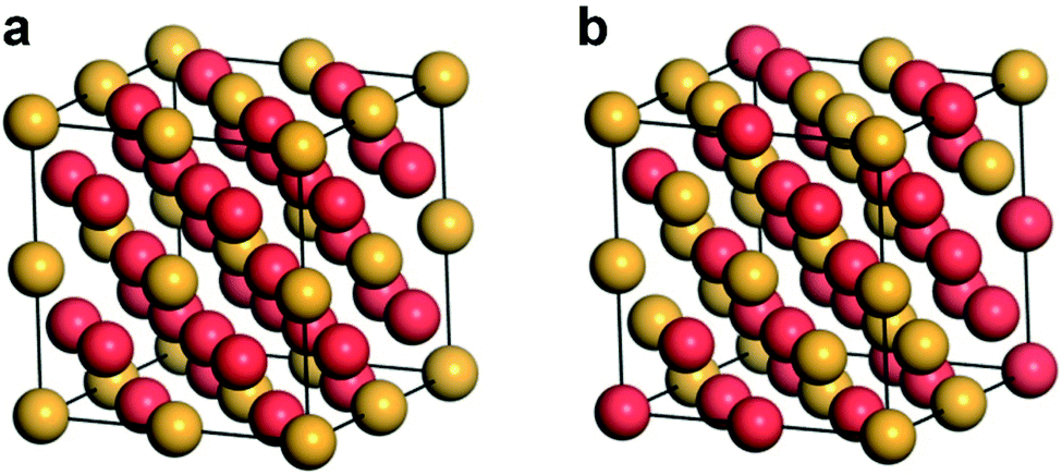 | ||
| Fig. 1 Atomic stacking models illustrating two typical crystal phases of binary Au-based nanoalloys: (a) chemically ordered phase and (b) chemically disordered phase of AB3. A and B represent Au (yellow ball) and the other metal (red ball), respectively. | ||
3. Characterization techniques of Au-based nanoalloys
In order to get a deep understanding of the structural characteristics of Au-based nanoalloys, various characterization techniques have been developed and utilized. In this section, we will briefly introduce some of the most commonly used characterization techniques based on morphology, structure and composition analysis.3.1. Morphological characterization
For Au-based nanoalloys, the microscopic morphology is of great importance in controlling their physicochemical properties. To determine the specific morphology, the most directly and commonly used technique is electron microscopy, including both scanning electron microscopy (SEM) and transmission electron microscopy (TEM).71,72 By using SEM and TEM, morphological information such as the size and shape of Au-based nanoalloys can be easily obtained. Compared with the images acquired by TEM, SEM provides better 3D images with a higher depth of view and a finer surface structure.73 In addition, the scanning probe microscopy, including atomic force microscopy (AFM) and scanning tunneling microscopy (STM), can provide the surface topography of Au-based nanoalloys with high (sometimes atomic) resolution with an atomically sharp tip scanning across the surface.74,753.2. Structural characterization
Numerous X-ray based techniques are widely used to reveal the structural characteristics of Au-based nanoalloys. As one of the most common and powerful techniques, X-ray diffraction (XRD) provides important structural information including crystal phase, crystallinity, crystal size, and precise lattice parameters as well as the qualitative chemical composition of the sample by measuring the angle and intensity of the diffraction lines.76 Grazing incidence small-angle X-ray scattering (GISAXS), a kind of X-ray based technique, is very sensitive to the surface of nanoalloys.77 Given this point, GISAXS can distinguish the ordered phases from the intermixed or phase-separated alloys. Besides the X-ray based techniques, several functions based on electron microscopy can also be used for the structural characterization of Au-based nanoalloys. Both high-resolution TEM (HRTEM) that offers a resolution of less than 1 Å and the selected area electron diffraction (SAED) can provide fine structural information through atomic imaging and electron diffraction, respectively.73 According to Vegard's law,78 the lattice structure of the uniformly mixed part and the area occupied by different atomic species in the phase-separated part are judged by the measured interplanar spacing and atomic arrangement. However, for bi- and multi-metallic nanoalloys, whose constituent elements (e.g., Au and Ag) have very similar lattice spacing, a combination of techniques such as scanning transmission electron microscopy (STEM) and high-angle annular dark-field (HAADF) imaging or Z-contrast (where Z is the atomic number) imaging techniques is a good choice.79 Because of their difference in atomic numbers, which is clearly visible in the Z-contrast images, the combined techniques (e.g., HAADF-STEM) can directly reveal the internal structure and chemical order in the Au-based nanoalloys. Alternatively, Raman spectroscopy,80 low-energy ion scattering (LEIS),73,81 and nuclear magnetic resonance (NMR)82 are also becoming viable tools in determining the precise structure of Au-based nanoalloys.3.3. Compositional characterization
The compositional characterization usually involves the identification of the type, content, chemical state, bonding, electronic structure and density of electronic states of each component element. The most common technique that is sensitive to the chemical composition is energy-dispersive X-ray microanalysis (EDX), which is often used in combination with SEM, TEM and other techniques.73 EDX utilizes an electron beam to excite X-ray signals that are used to obtain information about the chemical composition of nanoalloys with a depth of about 2 μm and a lateral resolution of around 1.5 nm. Another well-known and extensively used compositional characterization method is X-ray photoelectron spectroscopy (XPS). Based on the photoelectric effect, XPS can be used to analyze the surface element composition and chemical bond of nanoalloys according to the characteristic binding energy of elements.83–85 Different from the aforementioned techniques, infrared (IR) spectroscopy is based on the sensitivity of surface plasmon resonance to the composition and order of nanoalloys, which can be used for the in situ characterization of an alloy nucleation/growth process.59,86 In addition, with the increasing availability of synchrotron radiation facilities, X-ray absorption spectroscopy (XAS) has begun to be used by more and more researchers.87 Due to the uniqueness of the correspondence between the X-ray absorption spectrum and the element, the type, internal structure, local atomic environment of the element, and even the electron density, electronic configuration, coordination number and interatomic distance can be identified with this technique. Furthermore, more and more synchrotron radiation techniques, such as extended X-ray absorption fine structure (EXAFS) and near-edge X-ray absorption fine structure (NEXAFS) are gradually being developed and utilized to reveal the detailed atomic states and surrounding environments.734. Synthetic methods of Au-based nanoalloys
To date, various kinds of methods have been developed to synthesize Au-based nanoalloys.66,69,88–92 Usually, based on the introduction procedures of alloying elements, the synthetic methods of Au-based nanoalloys can be classified into the following two strategies.(a) Direct synthesis. This strategy commonly involves the introduction of alloying elements before the nucleation of nanoseeds. Au and alloying elements will simultaneously precipitate, nucleate, grow and then generate Au-based nanoalloys. The direct synthesis strategy usually includes a series of methods such as the co-reduction method, electrochemical deposition, thermal shock, laser ablation in liquid technique, scanning probe block copolymer lithography, etc.
(b) Elemental diffusion. In contrast to the aforementioned strategy, elemental diffusion is typically carried out step by step. The alloy structure starts to form on the surface or interface, and the morphology of the final products will partially inherit the characteristics of initial nanostructures. The elemental diffusion strategy mainly includes methods such as seed-mediated diffusion and thermal diffusion.
In this section, we will discuss the widely used synthetic methods of Au-based nanoalloys in recent years. Table 1 summarises the advantages and disadvantages of different synthetic methods. Specifically, the reaction principles, synthetic processes as well as typical alloy microstructures and components will be described. Some representative studies will be highlighted here to illustrate the key factors of each synthetic method.
| Methods | Advantages | Disadvantages |
|---|---|---|
| Co-reduction method | Facile operation; low equipment requirement; low cost | The composition of products is typically limited to classically miscible metals |
| Seed-mediated diffusion | Products with a narrow size distribution and well-defined structure | Time consuming; kinds of products are limited by the seeds |
| Electrochemical deposition | High-purity products; quick reaction | Involves templates; high cost |
| Thermal diffusion | Facile operation; low equipment requirement | High temperature; energy consuming |
| Thermal shock | Not limited to immiscible metals; uniform dispersion of elements; narrow size distribution; applicable to multi-element alloys; quick reaction | Ultra-high temperature; special equipment |
| Laser ablation in liquid technique | Facilitate the synthesis of metastable phases and defect-rich products | Kinds of products are limited by the targets; high equipment requirements; potential safety issues associated with the laser |
| Scanning probe block copolymer lithography | The composition and position of products are precisely controllable; good substrate adaptability; accessible to multi-element alloys | Complex operation; high equipment requirements |
4.1. Co-reduction method
In the co-reduction method, different metal precursors are simultaneously reduced with reductants to form nanoalloys in the presence of appropriate surfactants and solvents.93–95 This method is regarded as one of the most commonly used, effective and low-cost approaches for the controlled synthesis of Au-based nanoalloys.37,96–98 Note that the co-reduction method usually involves a one-step wet-chemical synthesis of Au-based nanoalloys. Considering that the co-reduction method involves two or more kinds of metal cations to be reduced to produce alloys in a specific environment, several key factors such as metal precursors, reductants and surfactants play very essential and critical roles in the synthetic system.99–101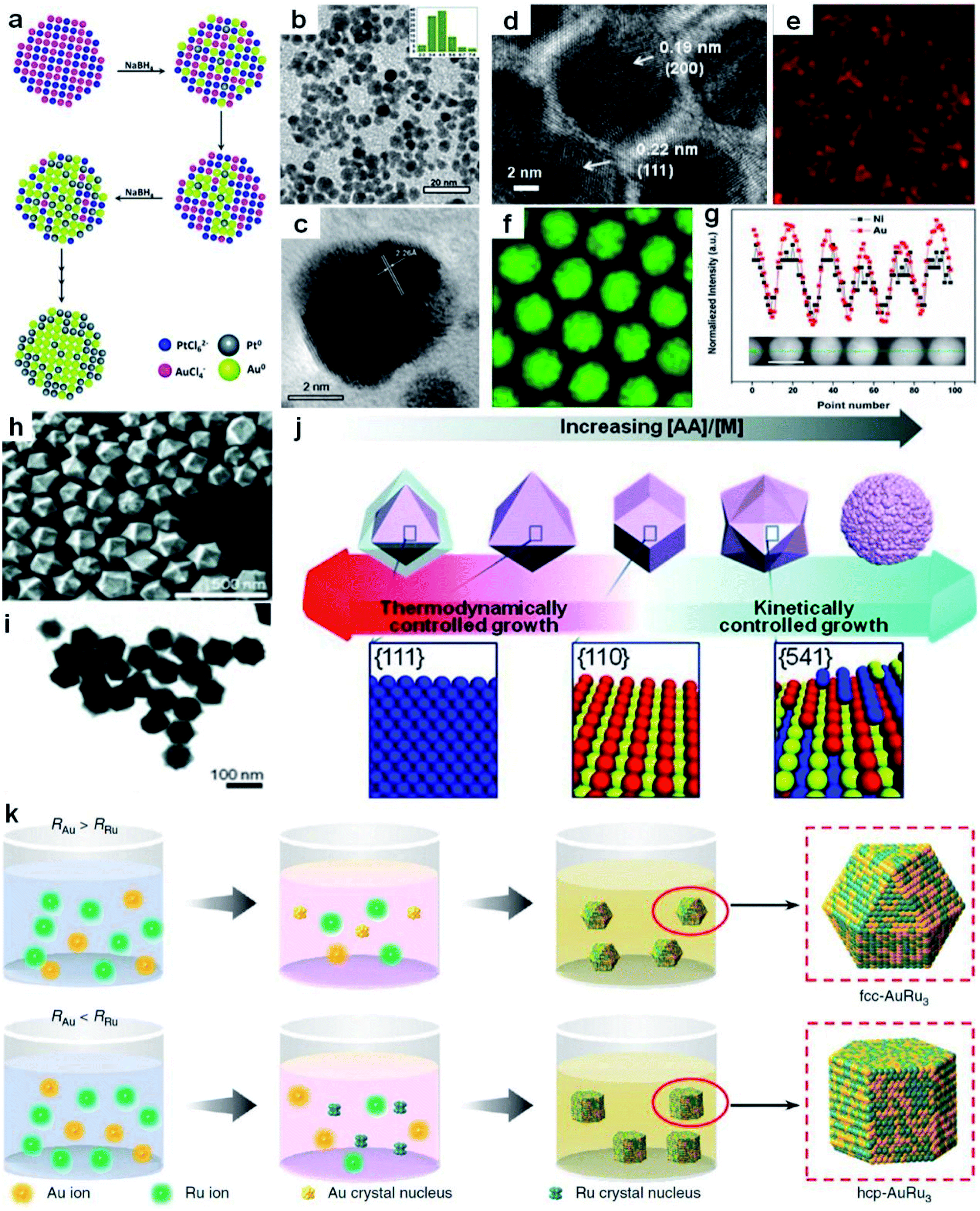 | ||
| Fig. 2 Co-reduction method for the synthesis of Au-based nanoalloys. (a) The scheme depicting the growth process of Au100−xPtx NPs. (b) TEM image of Au60Pt40 NPs with the particle size distribution in the inset. (c) HRTEM image of Au60Pt40 NPs. Reproduced with permission.102 Copyright 2013, Royal Society of Chemistry. (d–g) HRTEM image (d), elemental mappings of (e) Ni and (f) Au, and (g) EDX line-scanning profiles (inset shows the HAADF-STEM image of the corresponding NPs; scale bar, 10 nm) of Ni43Au57 NPs. Reproduced with permission.36 Copyright 2015, American Chemical Society. (h and i) SEM image (h) and TEM image (i) of hexoctahedral Au–Pd nanocrystals. (j) Schematic illustration of the relationship between the morphology of Au–Pd nanocrystals and their growth kinetics. Reproduced with permission.106 Copyright 2013, Wiley-VCH. (k) The scheme for the generation process of fcc and hcp AuRu3 nanocrystals. RRu and RAu represent the reduction rates of Ru and Au precursors, respectively. Reproduced with permission.34 Copyright 2018, Springer Nature. | ||
Recently, Sun et al. obtained NiAu alloy NPs by the co-reduction of HAuCl4·3H2O and Ni(acac)2 (acac denotes acetylacetonate) in the presence of oleic acid and oleylamine.36 Remarkably, it was found that the first reduction of HAuCl4·3H2O to Au facilitates Ni(acac)2 reduction at low temperature, overcoming the difficulties of a large Ni/Au miscibility gap and reduction potential gap in generating NiAu nanoalloys. A higher reaction temperature led to more Au content in NiAu alloy NPs. Specifically, the increase of the reaction temperature from 150 to 200 °C induced the formation of products ranging from Ni48Au52 to Ni43Au57. The HRTEM image (Fig. 2d), elemental mappings (Fig. 2e and f) and EDX line scanning profiles (Fig. 2g) were used to confirm the alloy nature of NiAu NPs. In addition, by changing the non-noble metal precursor from Ni(acac)2 to Co(acac)2 or Fe(acac)2, this method can also be readily extended to the synthesis of CoAu and FeAu alloy NPs.
By tuning the reaction kinetics with reductants, Au-based nanoalloys enclosed by high-index facets could also be obtained. As a representative study, Lee et al. co-reduced the HAuCl4/K2PdCl4 metal precursors in the presence of cetyltrimethylammonium chloride (CTAC) to obtain the hexoctahedral Au–Pd alloy nanocrystals enclosed by high-index {541} facets by using AA as the reductant.106Fig. 2h and i show the typical SEM and TEM images of the resultant hexoctahedral Au–Pd nanocrystals. When CTAC was used to reduce the metal precursors in the absence of AA, Au octahedra enclosed by {111} facets were first produced, followed by epitaxial growth of Pd layers on the preformed Au octahedra, generating the Au@Pd core–shell nanocrystals. After adding AA, alloy nanostructures were generated due to the enhanced reaction kinetics. Furthermore, through increasing the concentration ratio of AA to metal precursors, the nanocrystal growth behavior was transformed from thermodynamically controlled growth to kinetically controlled growth, as shown in Fig. 2j. Specifically, as the concentration ratio of AA to metal precursors was increased from 0.75 to 1, 4 and 20, the shape/morphology of Au–Pd alloy nanocrystals changed from octahedron (enclosed with {111} facets) to rhombic dodecahedron (enclosed with {110} facets), hexoctahedron (enclosed with high-index {541} facets) and quasi-flower/dendrites, respectively.
By precisely adjusting the reduction rate of metal precursors, nanoalloys with different crystal phases could also be obtained in the presence of specific surfactants. As a typical study, Kitagawa et al. found that AuRu3 nanoalloys with both fcc and hexagonal close-packed (hcp) phases were synthesized by controlling the reduction speed of appropriate Au and Ru precursors in the presence of CTAB (Fig. 2k).34 Specifically, by using diethylene glycol and ethylene glycol as reductants, the Au precursor (i.e., HAuBr4) was reduced slightly faster than the Ru precursor (i.e., K2Ru(NO)Cl5), which favored the production of fcc AuRu3 NPs. In contrast, when diethylene glycol was selected as the reducing agent, the Ru precursor (i.e., RuCl3) was reduced slightly faster than the Au precursor (i.e., HAuBr4) in the presence of CTAB, leading to the generation of hcp AuRu3 NPs.
4.2. Seed-mediated diffusion
Different from the co-reduction method, seed-mediated diffusion is a two-step approach that involves the preliminary synthesis of well-defined metal nanostructures as the seed, followed by the introduction of other metal elements into the seed to form nanoalloys.108–111 With the utilization of different metal precursors and seeds, various kinds of Au-based core–shell alloy NPs can be obtained in the presence of appropriate reductants and surfactants, such as Au–Ag, Au–Sn, Au–Pt, Au–Hg, Au–Cd and Au–Cu–Ag nanoalloys.112,113 Considering the synthetic mechanism, this sequential order also makes it suitable for generating core–shell structures, in which the size and morphology of the final products are closely related to the seeds. Besides the seeds, the type and concentration of metal precursors, reductants and surfactants as well as the reaction conditions also play important roles in this synthetic method.Here we illustrate the general process of seed-mediated diffusion using a representative study by Li et al., as shown in Fig. 3a.114 In this study, the pre-synthesized Au NPs (i.e., seeds) and Cu(CH3COO)2·H2O (i.e., Cu precursor) were first mixed in a solution containing oleic acid and tri-n-octylamine. Then, Cu2+ ions were reduced to highly reactive Cu atoms or clusters with oleic acid and tri-n-octylamine at 70 °C. Meanwhile, surfactants on the surface of Au seeds could desorb, leaving more active sites. When Cu atoms or clusters came into contact with these surface active sites, they diffused into Au seeds and formed Cu–Au nanoalloys. To be specific, when the Cu/Au atomic ratio was 3/1, ordered Cu3Au NPs were obtained by using 6.3 nm Au seeds at 300 °C (Fig. 3b). Meanwhile, intermetallic CuAu NPs were generated using 8.5–9.5 nm Au seeds at 280 °C when the Cu/Au atomic ratio was 1/1. Moreover, by using Au seeds with different sizes of 3.5 nm, 4.9 nm, and 6.3 nm, ordered AuCu NPs with the sizes of 4.2 ± 0.2 nm, 6.0 ± 0.2 nm, and 7.4 ± 0.3 nm were obtained, respectively. This work provides an effective protocol to synthesize intermetallic nanoalloys with well-defined compositions, sizes and structures.
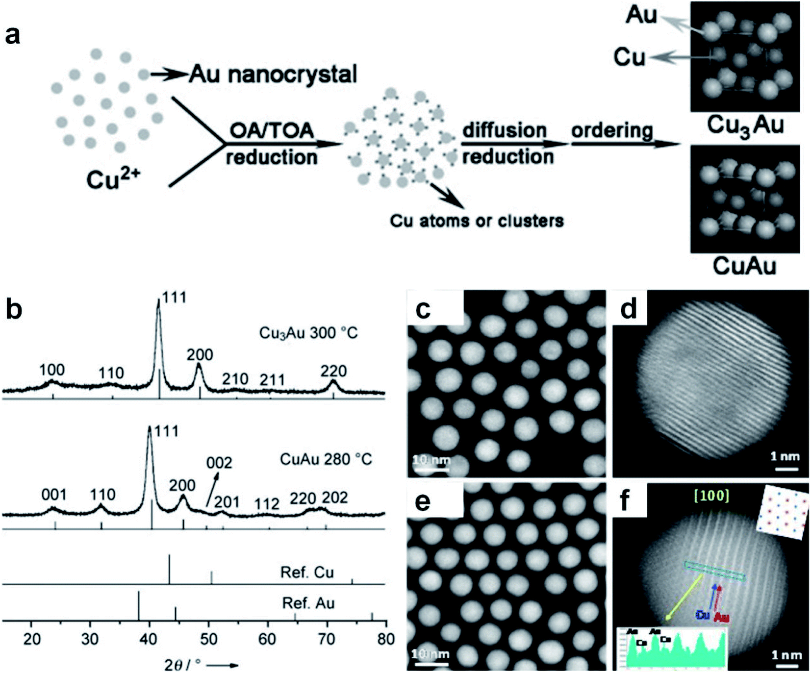 | ||
| Fig. 3 Seed-mediated diffusion for the synthesis of Au-based nanoalloys. (a) The scheme depicting the formation mechanism of intermetallic Cu–Au nanocrystals. (b) XRD patterns of CuAu and Cu3Au nanocrystals. Reproduced with permission.114 Copyright 2010, Wiley-VCH. (c–f) HAADF-STEM images of AuCu alloy NPs with the (c and d) fcc and (e and f) fct phases. Reproduced with permission.115 Copyright 2017, American Chemical Society. | ||
The reaction conditions such as temperature and time in the seed-mediated diffusion also play an important role in the formation of nanoalloys with different crystal phases. For instance, Zhu et al. synthesized fcc AuCu and face-centered tetragonal (fct) AuCu alloy NPs using Au NPs as the seed at different reaction temperatures.115 Specifically, the final products were mainly fcc AuCu alloy NPs at 210 °C, while fct AuCu alloy NPs were obtained when the temperature was increased to 290 °C. The HAADF-STEM characterization confirmed the formation of the uniform spherical fcc AuCu (Fig. 3c, d) and fct AuCu (Fig. 3e and f) alloy NPs. In another study, Yang et al. also synthesized fct Au–Cu alloy NPs in the presence of Au seeds.116 It was found that increasing the temperature and prolonging the time promote the generation of the fct phase.
4.3. Electrochemical deposition
Electrochemical deposition here refers to a process in which different kinds of metal ions are simultaneously reduced from their aqueous/non-aqueous solutions or molten salts by electron transfer from the working electrode, and subsequently deposit on the electrode to form alloy structures at specific potentials.117,118 With the assistance and precise control of porous templates (e.g., pore size, surface area, and pore structure), porous nanoalloys with high surface area and large pore volume can be obtained.119 The ion diffusion rate and charge transfer rate during electrochemical deposition have an obvious influence on the size of the resultant nanoalloys. Meanwhile, by controlling the key synthetic parameters, such as the current density, pH, concentration and electrolyte composition, the chemical composition, microstructure and size of the obtained nanoalloys can be delicately regulated.120–124The research work done by Nugraha et al. will be described here to elucidate a typical procedure of electrochemical deposition to obtain a mesoporous alloy film.120 In this work, an aqueous solution containing multiple kinds of metal precursors including HAuCl4, CuSO4 and NiCl2 was first mixed with the pre-prepared polymeric micelle assembly to generate the electrolyte solution. At a certain potential, the metal precursors in the mixed electrolyte solution were simultaneously reduced to their metallic states to form a mesoporous AuCuNi alloy film with an average pore size of about 28 nm. After that, the organic template was removed by solvent extraction (Fig. 4a). The composition of the final products can be easily adjusted by changing the metal precursor ratio in the initial electrolyte solution, while the thickness of the products can be readily controlled by adjusting the reaction time. Cross-sectional characterization indicated that a well-defined mesoporous structure of the AuCuNi film formed on the surface as well as throughout the whole cross-sectional area (Fig. 4b and c). And the HRTEM image (Fig. 4d) further confirmed the high crystallinity of the mesoporous AuCuNi membrane. Furthermore, all metal elements were uniformly distributed in the alloy film (Fig. 4e–j), proving that the resultant mesoporous AuCuNi membrane is free of phase segregation.
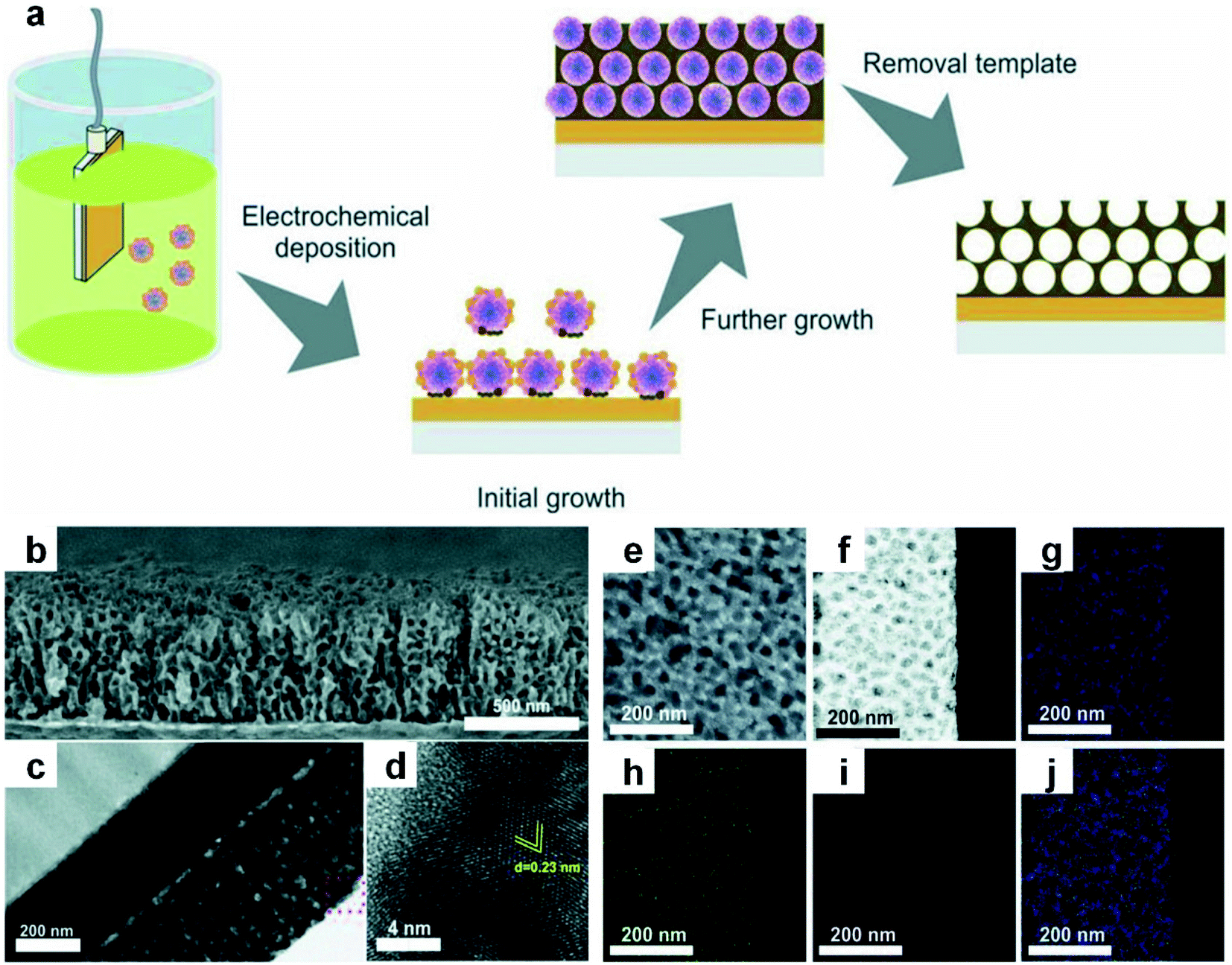 | ||
| Fig. 4 Electrochemical deposition of Au-based nanoalloys. (a) The schematic illustration of electrodeposition of mesoporous AuCuNi nanoalloy films. (b–d) SEM image (b), TEM image (c), and HRTEM image (d) of the cross-section of the Au60Cu35Ni5 mesoporous film that is obtained at the applied potential of −0.9 V (vs. Ag/AgCl). (e) SEM image of the top surface of the mesoporous Au60Cu35Ni5 film. (f–j) HAADF-STEM image (f) of the Au60Cu35Ni5 film and the corresponding EDX elemental mappings: (g) Au, (h) Cu, (i) Ni, and merged (j). Reproduced with permission.120 Copyright 2018, Wiley-VCH. | ||
Lyotropic liquid crystal (LLC) assisted electrodeposition is another promising method to synthesize Au-based nanoalloys with mesoporous and controllable structures.119 It is known that micelles can be generated when the concentration of amphiphilic surfactants is higher than the critical micelle concentration (CMC). Further increasing the concentration will lead to the formation of LLCs, in which the micelles adopt a specific arrangement. In the LLC solution,125 metal ions coordinate with the surfactants to generate a stable mesoporous structure. After electrochemical reduction, mesoporous alloy films can be obtained. As a typical study, Yamauchi et al. produced mesoporous Pt–Au binary nanoalloys by LLC-assisted electrodeposition.126 Specifically, the metal precursor solution containing H2PtCl6·6H2O, HAuCl4·4H2O, H2O, C16H33(OCH2CH2)8OH and ethanol was cast onto a conductive substrate to form LLCs after the evaporation of volatile solvents, followed by electrochemical deposition to generate mesoporous Pt–Au nanoalloys. Moreover, the framework composition of mesoporous Pt–Au nanoalloys could be easily modulated by changing the feed ratio of metal precursors in the solution. Generally, low Au content will generate well-ordered 2D hexagonal mesoporous nanostructures, while increasing the Au content would decrease the mesostructural order of bimetallic nanoalloys.
4.4. Thermal diffusion
Thermal diffusion is a method in which two or more kinds of metals in contact with each other are continuously fused to produce alloys by heating.127–129 Driven by thermodynamics, metal atoms with high Gibbs free energy would leave the original equilibrium position and migrate to the crystal lattices or vacancies of other metals at high temperature. The type of metal and size of raw materials together with the reaction conditions (e.g., temperature and holding time) are the main factors affecting the final structure and composition of the resultant nanoalloys. For instance, chemically ordered Au–Cu nanocubes can be obtained by heating the chemically disordered Au–Cu nanocubes at a certain temperature.130 In the synthesis of disordered Au–Cu nanocubes, gold and copper salts were first transferred from the aqueous phase to the organic phase with a low surface energy molecule, 1-dodecanethiol, as the stabilizing and capping agent, followed by the thermolysis of the metal precursors. Here, different ratios of metal precursors (i.e., HAuCl4 and CuCl2) were adopted to generate disordered Au–Cu nanocubes with different compositions (e.g., AuCu3, AuCu and Au3Cu). Importantly, it was demonstrated theoretically and experimentally that the disordered AuCu nanocubes can be transformed into an ordered structure at an appropriate temperature. For instance, AuCu nanocubes underwent a disorder-to-order phase transition after heating at 120 °C. But it should be noted that heating at a very high temperature (e.g., 200 °C) will induce a reverse order-to-disorder phase transition.The elemental distribution of metal materials can be tuned by thermal annealing, making it feasible to prepare nanoalloys from pre-synthesized bi-/multi-nary metal nanostructures. For example, by using silica-coated Au@Ag core–shell nanorods with a fixed composition and element distribution as the research object, Hoeven et al. studied their atomic redistribution (i.e., alloying) during the heating process.131 EDX mappings showed that the boundary between the Au core and the Ag shell became blurred and then overlapped along with the temperature increase from 25 °C to 475 °C (Fig. 5a). Interestingly, alloying usually happened at a certain temperature which corresponded to the steep change in the alloying degree–temperature curves (Fig. 5b and c). Moreover, the degree of alloying depended on the volume and composition of particles. For particles with a similar composition (i.e., similar Ag content), the smaller the volume, the lower the temperature required for complete alloying (Fig. 5b), which is ascribed to the increased atomic mobility at smaller particle dimensions. For particles with a similar volume, the decrease of Ag content led to a significant drop in the starting temperature for alloying (Fig. 5c). This work indicated that both metal composition and nanoscale dimension should be considered in order to obtain desirable atomic redistribution by thermal diffusion. Recently, Zhang et al. observed a reversible transformation between the core–shell and alloy structures in Ni–Au NPs during the CO2 hydrogenation.35 The initial NPs adopted the Ni–Au core–shell structure that consisted of an fcc Ni core and 2–3 atomic layers of the Au shell. When the temperature was increased to 600 °C during CO2 hydrogenation, the structure of Ni–Au NPs changed from core–shell to alloy (Fig. 5d). Interestingly, when the temperature was brought down to 400 °C, an Au atomic layer epitaxially re-segregated along the Ni (200) plane (Fig. 5e), which proved the reversibility of this alloying/dealloying process.
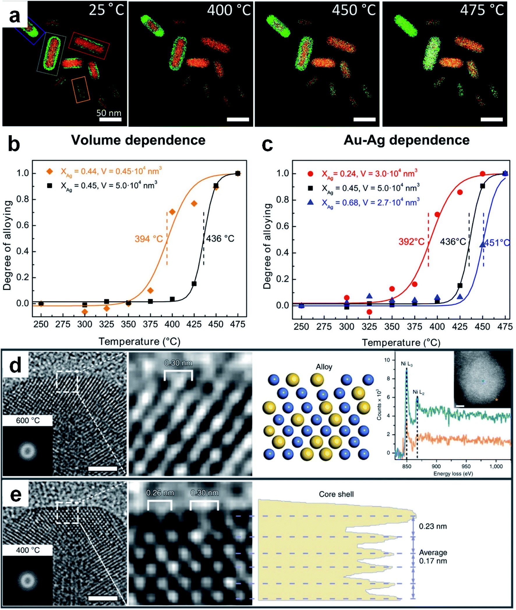 | ||
| Fig. 5 Thermal diffusion for the preparation of Au-based nanoalloys. (a) EDX elemental maps of silica-coated Au@Ag core–shell nanorods acquired at 25 °C, 400 °C, 450 °C, and 475 °C, respectively. (b) The dependence of the alloying degree on the particle volume for silica-coated Au@Ag nanorods. (c) The alloying degree with respect to Ag-content in silica-coated Au@Ag nanorods. Reproduced with permission.131 Copyright 2018, American Chemical Society. (d) From left to right, the HRTEM image (scale bar: 2 nm) with a Thon ring in the inset, enlarged HRTEM image of the surface region, schematic atomic structure, and point analysis of the electron energy loss spectra with a HAADF-STEM image (scale bar: 2 nm) of a Ni–Au NP at 600 °C in the inset. (e) From left to right, the HRTEM image (scale bar: 2 nm) with a Thon ring in the inset, enlarged HRTEM image of the surface region, and phase-contrast profile of a Ni–Au NP at 400 °C. Reproduced with permission.35 Copyright 2020, Springer Nature. | ||
4.5. Thermal shock
Thermal shock refers to the process of instantaneous melting, disintegration and solidification of metal precursors to form nanoalloys at extremely high temperatures (∼2000 K) and ultra-large heating and cooling rates (∼105 K s−1).132 In a typical thermal shock method such as carbothermal shock, the required metal precursors dissolved in solution are assembled and dropped into the hole grooves of carbon supports by using an injector, followed by a rapid thermal shock to decompose the metal precursors to form alloys or high-entropy alloys. As a representative study, Hu et al. applied this method to boost the nucleation and overcome the heat-induced phase separation during the growth of high-entropy alloys.132 By using this method, a series of Au-based nanoalloys were obtained, including binary AuCu NPs, ternary AuCuSn NPs, and high-entropy alloy NPs such as AuPtPdCoNiFeCu and AuPtPdCoNiFeCuSn. Importantly, as this method requires an extremely rapid heating rate, the synthesis is usually completed within a few seconds. Furthermore, even though the metal elements are normally immiscible, they can form atomically mixed alloys by using this method.1334.6. Laser ablation in liquid technique
Laser ablation in liquid technique (LALT) refers to that in which metal targets and metal salts are simultaneously vaporized and decomposed under high energy laser irradiation, respectively, followed by combination with each other to form alloys through fast quenching.134–138 Due to the mild conditions and broad adaptability, LALT has become a burgeoning technology to fabricate materials with novel metastable nanostructures.139,140 In this method, laser irradiation has two functions: to sublime the solid target into a vapor state and reduce high-valence-state metal ions in the reaction solution. It should be mentioned that, apart from the solvent properties and external environments, the type of laser source used in LALT is considered as a very important factor for synthesizing various nanoalloys.134,135,137As a representative study, a metastable RuAu single atom alloy (SAA) was prepared via vaporizing the immersed Ru target and reducing HAuCl4 in aqueous solutions using a laser with a pulse width of 7 ns (Fig. 6a).135 It was found that the HAuCl4 aqueous solution with different concentrations could lead to products with different compositions. When the concentration of HAuCl4 was 0.2 mM, the obtained RuAu NPs exhibited an average size of 8 nm (Fig. 6b), in which Au and Ru were uniformly distributed throughout the particles (Fig. 6c). The high resolution HAADF-STEM images showed that the individual Au atoms (marked by red circles with higher pixel intensity) occupied some positions of Ru lattices, indicating the SAA feature of the resultant RuAu NPs (Fig. 6d and e). This work suggested that LALT is an effective technique to generate SAAs despite their components being immiscible at the bulk scale.
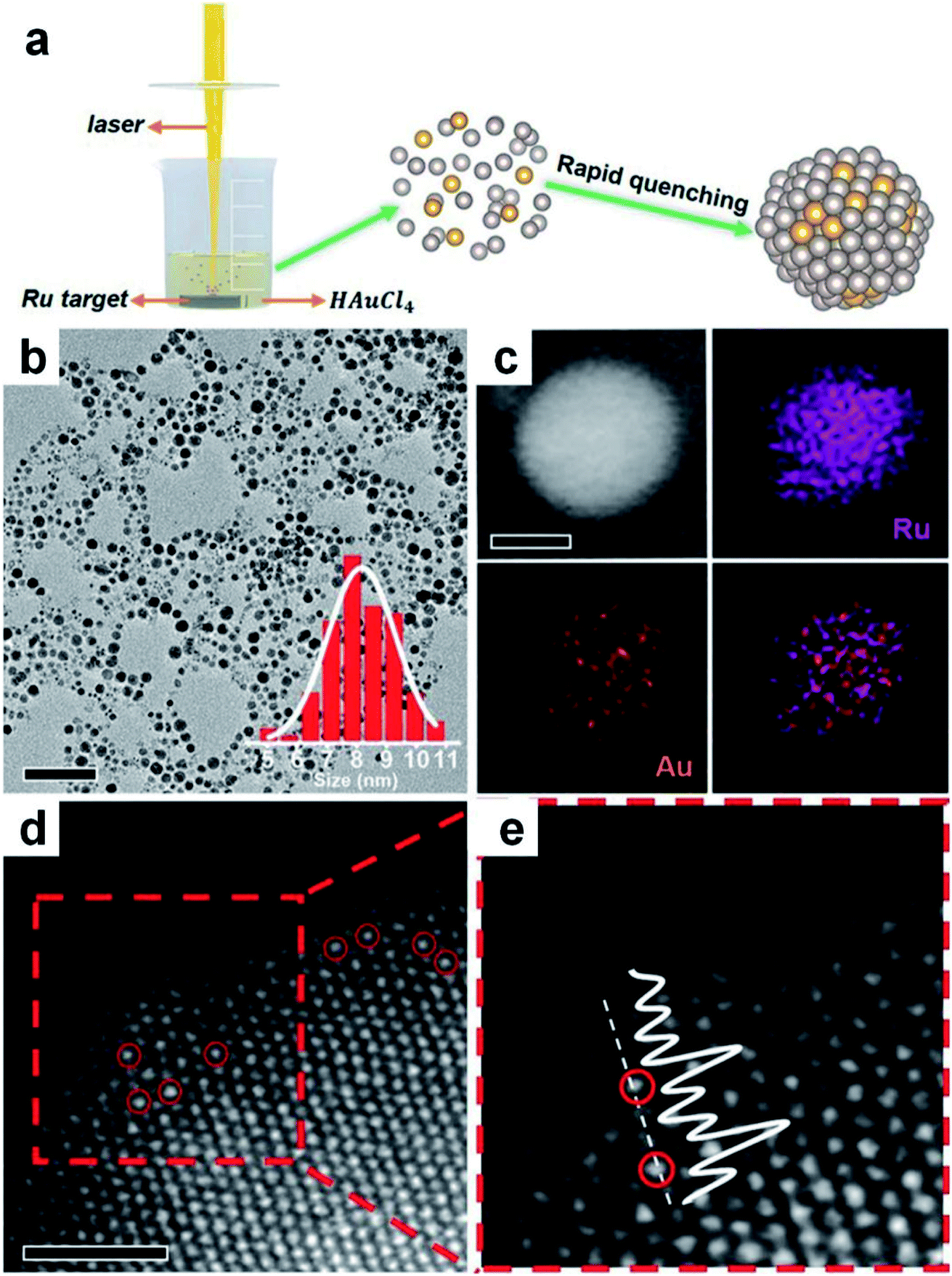 | ||
| Fig. 6 Synthesis of Au-based nanoalloys with the laser ablation in liquid technique. (a) Schematic illustration of LALT in the synthesis of RuAu SAA NPs. (b) TEM image of RuAu NPs (scale bar: 50 nm) with particle size distribution in the inset. (c) HAADF-STEM image (scale bar: 5 nm) and elemental mappings of Ru, Au and the overlap. (d and e) High-resolution HAADF-STEM image of RuAu NPs (d), in which Au atoms are marked with red circles (scale bar: 1 nm), and (e) the enlarged image of the red dashed rectangle of (d). Reproduced with permission.135 Copyright 2019, Wiley-VCH. | ||
Due to the strong quenching effect, LALT is a unique technique that can overcome the inherent composition limitations of synthetic alloys. For instance, Vassalini et al. successfully synthesized Au–Fe nanoalloys through the laser irradiation of a kinetically stable Au–Fe bulk alloy (i.e., the solid target) in ethanol solution.141 It was observed that the electronic structure of Fe was significantly modified in the Au–Fe nanoalloy, while the Au electronic structure remained quite similar to that of pure Au. Notably, there were up to 11 at% Fe atoms that were stably and homogeneously incorporated into the Au lattice, which far exceeded the thermodynamic limit of Fe-doped Au nanomaterials under ambient conditions.
Generally, compared with the other synthetic methods of Au-based nanoalloys, LALT possesses the advantages of faster reaction speed and higher degree of alloying. However, due to the utilization of lasers, high requirements on the experimental setup and potential safety issues might limit the wide application of this technique.
4.7. Scanning probe block copolymer lithography
Although the methods introduced above can efficiently synthesize Au-based nanoalloys with precise morphology and composition, spontaneous aggregation of nanoalloys commonly appears, which could decrease their catalytic performance. In comparison, scanning probe block copolymer lithography (SPBCL), which was first proposed by Mirkin et al.,142 can not only realize the growth and position control of individual NPs, but also obtain arbitrary patterns on a large area and multiple surfaces.143–145 It is a universal method to transfer the phase-separating block copolymer inks containing metal precursors to the desired position by scanning probe lithography.146,147 The size of NPs can be adjusted by changing the volume of block copolymer inks and the type and proportion of loaded metal precursors.Here we use a binary alloy reported by Chen et al. as an example to illustrate the general working principle of SPBCL.148 In a typical process, the ink composed of metal precursors (e.g., HAuCl4/Na2PdCl4) and poly(ethylene oxide)-block-poly(2-vinylpyridine) was first deposited onto the specific position of the substrate with the AFM tips. Later, after annealing in Ar at 150 °C for 48 h, and successively in H2 at 500 °C for 12 h, binary alloy NPs (e.g., Au–Pd) with good crystallinity and homogeneous elemental distribution were in situ formed on the substrate. Besides, SPBCL also provides a general synthetic strategy for the structure and composition control of multicomponent nanoalloys.149,150
5. Catalytic applications of Au-based nanoalloys
Because of the unique physicochemical properties of Au-based nanoalloys, their catalytic applications have also been widely explored in recent years. Regarding the different structural and component characteristics of Au-based nanoalloys, electrocatalysis and heterogeneous catalysis are two dominant catalytic applications in which they have been applied to. In this section, we will focus on introducing the widely studied electrocatalytic reactions (e.g., the CO2 reduction reaction (CO2RR), oxygen reduction reaction (ORR), hydrogen evolution reaction (HER), oxygen evolution reaction (OER) and small organic molecule oxidation reaction) and several representative heterogeneous catalytic reactions (e.g., the CO oxidation reaction and typical heterogeneous catalytic reactions in chemical engineering) with Au-based nanoalloys, in which the general structure/composition-performance relationships will be discussed as well.5.1. CO2 reduction reaction
With the dramatic increase in the combustion of fossil fuels, the concentration of CO2 in the atmosphere has soared to an appalling level (i.e., over 410 ppm), which leads to the undesirable consequence to the global environment and climate. As a kind of non-toxic, copious and renewable carbon source, CO2 can be converted from unfavorable greenhouse gas to useable energy resources, which not only solves the environmental and climate problems, but also inspires a new route for the development of renewable energy resources.151,152 However, the highly thermodynamically stable CO2 (e.g., the C![[double bond, length as m-dash]](https://www.rsc.org/images/entities/char_e001.gif) O bond dissociation energy is ∼750 kJ mol−1) is quite inert for chemical reactions under ambient conditions.153 Therefore, catalysts are needed to activate CO2 and thus decrease the reaction energy barriers. In recent years, the electrochemical CO2RR that converts CO2 into value-added fuels and chemicals has proven to be an efficient and economical route for CO2 fixation at room temperature and ambient pressure.154 Through numerous efforts over the past few decades, various Au-based nanoalloys with tunable catalytic activity, intriguing selectivity and good stability have been developed as efficient CO2RR catalysts. Table 2 shows the catalytic performance of different Au-based nanoalloys for the CO2RR.
O bond dissociation energy is ∼750 kJ mol−1) is quite inert for chemical reactions under ambient conditions.153 Therefore, catalysts are needed to activate CO2 and thus decrease the reaction energy barriers. In recent years, the electrochemical CO2RR that converts CO2 into value-added fuels and chemicals has proven to be an efficient and economical route for CO2 fixation at room temperature and ambient pressure.154 Through numerous efforts over the past few decades, various Au-based nanoalloys with tunable catalytic activity, intriguing selectivity and good stability have been developed as efficient CO2RR catalysts. Table 2 shows the catalytic performance of different Au-based nanoalloys for the CO2RR.
| Catalysts | Electrolyte | Major products and maximum FE | Stability | Ref. |
|---|---|---|---|---|
| a SCA, submicrocone arrays; NCF, nanoporous Cu film; SCE, saturated calomel electrode; Ag/AgCl, Ag/AgCl reference electrode; CNFs, carbon nanofibers; CSNP, core–shell nanoparticle. | ||||
| AuCu/Cu-SCA | 0.5 M KHCO3 | C2H5OH (29 ± 4%) and C2H4 (16 ± 4%) at −1.0 VRHE | No obvious decrease after 24 h at −1.0 VRHE | 212 |
| Au1Sn2 NPs | 0.1 M NaHCO3 | HCOOH (42%) at −1.1 VRHE | Slight increase after 10 h at −1.0 VRHE | 165 |
| Ordered AuCu NPs | 0.1 M KHCO3 | CO (∼80%) at −0.77 VRHE | No obvious decrease after 12 h at −0.76 VRHE | 116 |
| Cu63.9Au36.1/NCF | 0.5 M KHCO3 | CH3OH (15.9%) and C2H5OH (12%) at −1.1 VSCE | — | 213 |
| Pd5@Au95 NPs | 0.1 M KHCO3 | CO (∼80%) at −0.5 VRHE | — | 52 |
| Twisted Pd0.8Au nanowires | 0.5 M KHCO3 | CO (94.3%) at −0.6 VRHE | 15.7% decrease after 8 h at −0.6 VRHE | 214 |
| Au3Cu nanocubes | 0.5 M KHCO3 | CO (90.2%) at −0.38 VRHE | No obvious decrease after 30 h at −0.38 VRHE | 215 |
| AgPd-edged Au nanoprisms | 0.1 M HClO4 | HCOOH (49%) at −0.18 VRHE | No obvious decrease after 12 h at −0.18 VRHE | 216 |
| Au75Pd25 NPs | 0.1 M KHCO3 | CO (∼80%) at −0.5 VRHE | — | 217 |
| Au1Ni1-CNFs | 0.1 M KHCO3 | CO (92%) at −0.98 VRHE | No obvious decrease after 16 h at −0.98 VRHE | 218 |
| AuFe-CSNP | 0.5 M KHCO3 | CO (97.6%) at −0.4 VRHE | No obvious decrease after 90 h at −0.5 VRHE | 219 |
| Pd@Pd3Au7 nanocubes | 0.1 M KHCO3 | CO (94%) at −0.5 VRHE | No obvious decrease after 8 h at −0.7 VRHE | 161 |
| Au94Pd6 NPs | 0.1 M HClO4 | CO (94.7%) at −0.6 VRHE | No obvious decrease after 12 h at −0.6 VRHE | 163 |
| Cu3Au nanowire arrays | 0.1 M KHCO3 | C2H5OH (48%) at −0.5 VRHE | 14% decrease after 8 h at −0.7 VRHE | 166 |
| AuAgPtPdCu NPs | 0.5 M K2SO4 | CH4 (38.0%) and C2H4 (29.5%) at −0.9 VAg/AgCl | Steady decrease after 1 h at −0.8 VAg/AgCl | 167 |
| Pd–Au electrode | 0.1 M KH2PO4/0.1 M K2HPO4 | CO (30.9%) at −0.6 VRHE | — | 168 |
For the electrocatalytic reduction of CO2, the first step is the adsorption of CO2 onto the surface of electrocatalysts. In addition to the physical adsorption, CO2 molecules can be partially charged and be adsorbed chemically.155 Owing to the lone pair of electrons of the O atom and the positively charged C atom, CO2 molecules can be easily adsorbed on the electrocatalyst surface by donating the lone pair of electrons to the Lewis acid centers or accepting electrons from the Lewis base centers, weakening the CO bonds and lowering the activation energy for subsequent electrochemical processes.156 Based on previous studies, the generation of different CO2-reduction products (e.g., C1 and C2+ products) usually involves distinct reaction pathways, which are closely associated with the formation of different intermediate species.157,158 For the generation of C1 products such as CO, methane, methanol and formic acid, the CO2 reduction could adopt different pathways, in which the formation of different intermediates (e.g., *CO2˙−, *CO, and *COOH) on the surface of electrocatalysts is likely responsible for generation of the ultimate products. For the production of C2 products such as glyoxal, glycolaldehyde, ethylene glycol and acetaldehyde, the formation of *CO and its further hydrogenation to form *CHO and *COCHO may give rise to the final products. For the production of C3 products such as propionaldehyde, n-propanol and acetone, it was hypothesized that the intermolecular C–C coupling between C1 and C2 intermediates and the following proton/electron transfer result in the formation of advanced products. Obviously, the CO2RR typically involves a series of distinct intermediates on the catalyst surface. And the intermediates are very sensitive to the electronic structure and surface state of electrocatalysts. The ideal electrocatalysts are supposed to bind with the key intermediates moderately. This is because very weak binding impedes the beginning of the reaction while the excessively strong binding results in the difficulty for further reactions. Therefore, by tuning the binding capacity of electrocatalysts to the different intermediates, the selective synthesis of particular fuels/chemicals could be well achieved. Based on this idea, abundant efforts have been devoted to selectively reducing CO2 to high-value fuels and chemicals with electrocatalysts, such as nanoalloy electrocatalysts.
As for nanoalloy electrocatalysts, two notable effects, i.e., the electronic effect and geometric effect, play crucial roles in determining the electrocatalytic CO2 reduction performance. As for the electronic effect, the interaction of d-bands of transition metals with adsorbates governs the binding strength (the lower d-band center relative to the Fermi level indicates the weaker binding strength for the occupancy of anti-bonding states159), and thus largely determines whether the catalytic reaction occurs and how it proceeds. As for the geometric effect, the interaction ability of metal atoms with adsorbates would be altered if the environment around the atoms gets changed.160 For example, more content of Cu in Au–Cu alloy NPs results in a higher d-band center, which is capable of interacting with more kinds of reaction intermediates. Importantly, it was found that having a Cu atom adjacent to an Au–C bond will stabilize *COOH while that with *CO remains unchanged, resulting in enhanced CO production activity.159 Based on this point, Gong et al. synthesized ultrathin Pd–Au shells on Pd nanocubes to catalyze the reduction of CO2 to CO with a Faradaic efficiency (FE) close to 100% in a potential range from −0.6 to −0.9 V (vs. the reversible hydrogen electrode (RHE)).161 With the addition of Au atoms, the d-band center of Pd atoms moves down relative to the Fermi level, which weakens the strong Pd–C bond and makes it easy to desorb *CO. In addition, the electron transfer between Au and Pd atoms facilitates the generation of *COOH on the surface of the ultrathin Pd–Au shell. The results indicated that the Pd–Au nanoalloy with an appropriate composition exhibits superior CO2RR performance to pure Au and Pd.
At present, most of the Au-based nanoalloy catalysts are in favor of generating C1 products, especially CO.162,163 As a typical study, Smith et al. synthesized Au–Pt bimetallic thin films with different compositions and morphologies for electrocatalytic reduction of CO2.164 It revealed the general relationship between the formation of CO (main product)/HCOOH and the catalyst composition. The highest FE of CO for pure Au is about 77% at a potential of −0.6 V (vs. RHE, Fig. 7a), while it shows a decreasing trend with the increase of Pt content. To gain a deep understanding of the relationship between the alloy composition and CO2RR performance, the FE and partial current density for CO at various potentials were measured (Fig. 7b and c). It can be seen that the FE for CO (Fig. 7b) increases while the onset potential for CO positively shifts (Fig. 7c) as the Au content increases, suggesting that the composition of Au-based nanoalloys does have an obvious effect on their CO2RR performance. Specifically, with the increase of Au content, the d-band center will be shifted away from the Fermi level, which decreases the binding energy of *COOH and *CO and thus changes the CO2-reduction performance. Besides, for HCOOH, the FEs corresponding to all the catalysts with different compositions were always below 5%. In another study, Janáky et al. used Au–Sn NPs as electrocatalysts for the CO2RR, in which the final products also only contain HCOOH, CO and H2 (Fig. 7d).165 When the atomic ratio of Au/Sn reached 1/2, the Au–Sn nanoalloy exhibited the lowest overpotential and best stability. Specifically, the current density was relatively stable at about 8 mA cm−2 within 10 h of testing at −1.0 V (vs. RHE, Fig. 7e).
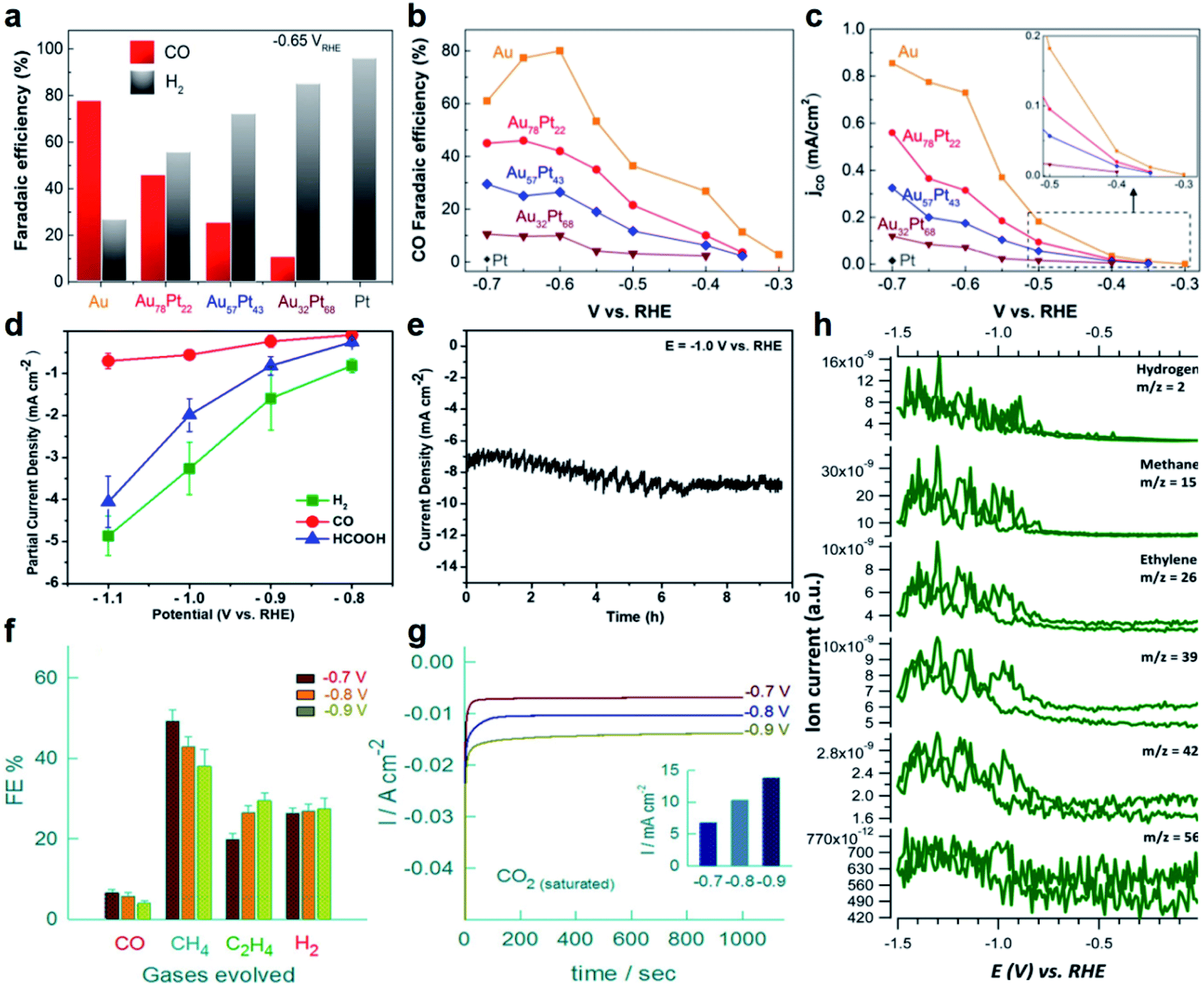 | ||
| Fig. 7 The electrocatalytic performance of Au-based nanoalloys towards the CO2RR. (a) The FE of CO and H2 on Au, Pt and Au–Pt alloys in CO2-saturated 0.1 M KHCO3 solution (pH = 6.8) at −0.65 V (vs. RHE). (b) The FE of CO on Au and Au–Pt alloys at different potentials. (c) The partial current density for CO on Au and Au–Pt alloys at different potentials. Inset: zoom-in profiles of the CO partial current density plots. Reproduced with permission.164 Copyright 2017, Elsevier. (d) The partial current densities of CO, HCOOH and H2 of the Au1Sn2 catalyst at different potentials in the CO2RR. (e) Long-term durability profile of the Au1Sn2 catalyst in CO2-saturated 0.1 M NaHCO3 solution at −1.0 V (vs. RHE). Reproduced with permission.165 Copyright 2018, American Chemical Society. (f) The FE of CO, CH4, C2H4 and H2, and (g) chronoamperometric responses of a high-entropy alloy (i.e., AuAgPtPdCu NPs) in CO2-saturated K2SO4 solution at different potentials (Inset: the corresponding current densities at different potentials). Reproduced with permission.167 Copyright 2020, American Chemical Society. (h) Generation of H2, CH4, C2H4, C3 and C4 hydrocarbons on the Pd–Au alloy electrode in 0.1 M KH2PO4/K2HPO4 buffer electrolyte (pH = 6.7). Reproduced with permission.168 Copyright 2016, Royal Society of Chemistry. | ||
In contrast to C1 products, the selective electroreduction of CO2 to high-value C2+ products (e.g., hydrocarbons and alcohols) is more challenging due to the difficulty in C–C coupling and subsequent complex reaction pathways. Cu and Cu-based catalysts are considered to be the dominant metal-based materials that can selectively reduce CO2 to C2+ products with a relatively high efficiency. Considering its merits, Cu has been introduced into Au to adjust the electronic structure of Au-based nanoalloys, aiming at optimizing the CO2RR activity and selectivity towards C2+ products. For example, He et al. used constant-potential pulse electrodeposition to prepare CuxAuy nanowire arrays (NWAs) with a high aspect ratio.166 When employed as electrocatalysts for the CO2RR, it was found that CuxAuy NWAs could significantly reduce the onset potential of alcohols. As for the Cu3Au NWAs with an optimized composition, they can selectively reduce CO2 to ethanol with an FE of up to ∼48% at a low potential of −0.5 V (vs. RHE). The superior ethanol selectivity of Cu3Au NWAs might arise from the synergistic effects of the electronic structure and morphology that increase the adsorption of *CO on the nanowire surface and promote the following reduction of *CO to ethanol through a dimerization process.
Apart from the binary Au–Cu alloys, multi-nary Au–Cu–M nanoalloys have also been developed in order to drive the CO2RR towards the formation of more kinds of C2+ products. In a typical study by Biswas et al., a high-entropy alloy containing five metal elements (i.e., AuAgPtPdCu NPs) was prepared, which can effectively catalyze the conversion of CO2 to hydrocarbon products using 0.5 M K2SO4 as the electrolyte.167 As shown in Fig. 7f, methane (CH4) and ethylene (C2H4) are the main products in a potential range from −0.7 to −0.9 V (vs. Ag/AgCl). Importantly, the FE of C2H4 reached the highest value of 29.5% at −0.9 V (vs. Ag/AgCl). In the chronoamperometric response measurements, the steady-state current densities within the initial 1000 s are −6.83, −10.31 and −13.81 mA cm−2 at various potentials of −0.7, −0.8, and −0.9 V (vs. Ag/AgCl), respectively (Fig. 7g). It was proposed that the excellent CO2RR performance of high-entropy AuAgPtPdCu NPs is attributed to the existence of redox-active Cu and the synergistic effect between multiple metal elements. This study demonstrated the feasibility of improving the CO2RR performance through the design and synthesis of high-entropy alloys.
Besides Cu, the combination of other metals with Au to form Au-based nanoalloys can also promote the formation of C2+ products in the CO2RR. As a representative study, Koper et al. reported that Pd–Au alloys formed by electrochemical deposition could electrochemically reduce CO2 to various hydrocarbons ranging from C1 to C5 products.168 Since the potential for reducing *CO to hydrocarbons is much lower than that for reducing CO2 to hydrocarbons, *CO is a key reaction intermediate for the generation of hydrocarbons. By alloying Au (with weak binding to *CO) with Pd (with strong binding to *CO), it achieved a precise and balanced control of *CO binding on the catalyst surface during the CO2RR. The online electrochemical mass spectrometry (OLEMS) indicated that the CO2-reduction products on Pd–Au alloys contain hydrogen, C1 (CH4, HCOOH and methanol), C2 (C2H4, ethane, ethanol and acetic acid), C3 (propane and propylene), C4 (1-butene, isobutane and butane) and C5 (2-methyl-butane, pentane and pentene) species (Fig. 7h). This work suggested the possibility of obtaining higher hydrocarbons (e.g., C3 to C5) from CO2 reduction by fine tuning the binding energy of *CO on the catalyst surface.
5.2. Oxygen reduction reaction
The ORR is an important reaction that is widely used in energy conversion devices (e.g., fuel cells and metal–air batteries) and the production of hydrogen peroxide (H2O2). It is well-known that the electrocatalytic ORR typically involves two kinds of mechanisms, i.e., 2-electron and 4-electron pathways.169,170 In acidic or neutral aqueous solutions, the ORR mainly occurs through the 2-electron pathway (H2O2 is formed) or the 4-electron pathway (H2O is produced). However, in non-aqueous aprotic solvents and/or in alkaline solutions, a 1-electron pathway is also able to emerge, realizing the conversion of O2 to superoxide (O2−). For applications in fuel cells and metal–air batteries, the 4-electron pathway is recognized as the favorable one due to its high energy-conversion efficiency,171 whereas the 2-electron pathway is supposed to dominate when it aims to replace the energy-intensive anthraquinone process with a green method to produce H2O2. Therefore, for different situations, the ORR pathway should be rationally regulated to meet the requirements of practical applications.To better modulate the ORR pathway, it is significant to understand the reaction mechanisms, especially the 2-electron and 4-electron pathways. As indicated by previous studies, the adsorption mode of O2 on the catalysts plays a crucial role in controlling the reaction pathway. To be specific, three kinds of adsorption models have been reported, including the Pauling model (end-on adsorption), Griffiths model (side-on adsorption) and Bridge model (bridge-on adsorption).172,173 In the Pauling model, only one atom of the O2 molecule interacts with the active site of electrocatalysts, which is favorable to maintain the O–O bonding and thus desirable for the formation of *OOH via the 2-electron pathway. As for the Griffiths model, two atoms of the O2 molecule interact with one active site, which will weaken the O–O bond and favor the 4-electron pathway. If the active sites of electrocatalysts strongly interact with O2, the bridge-on adsorption will occur, in which both atoms of O2 interact with two active sites simultaneously. In this situation, the O–O bonding is easily broken to produce two O* through the 4e-electron pathway. Moreover, the interaction capability of electrocatalysts with different intermediates generated in the ORR, such as oxygenated (O*), hydroxyl (OH*) and superhydroxyl (OOH*) species, also influences the reaction thermodynamics and kinetics, resulting in different products (i.e., selectivity) and current densities (i.e., activity). Hence, for nanoalloy electrocatalysts, it is feasible to manipulate the ORR pathway by tuning their size, composition and structure, considering the unique electronic effect and geometric effect in alloys. Table 3 shows the catalytic performance of different Au-based nanoalloys for the ORR.
| Catalysts | Electrolyte | Catalytic activity | Stability | Ref. |
|---|---|---|---|---|
| a NWNs, nanowire-networks; MA, mass activity; SA, specific activity; E1/2, half-wave potential; pTBA, poly(benzoic acid-2,2′:5′,2′′-terthiophene); NAs, nanothorn assemblies; ECSA, electrochemically active surface area. | ||||
| S-doped AuPbPt NWNs | 0.1 M HClO4 | MA (0.59 A mg−1) and SA (0.42 mA cm−2) at 0.9 VRHE | 47 mV increase of E1/2 after 15![[thin space (1/6-em)]](https://www.rsc.org/images/entities/char_2009.gif) 000 cycles (0.6–1.0 VRHE) 000 cycles (0.6–1.0 VRHE) |
220 |
| Pt–Au10–Co25 NPs | 0.1 M HClO4 | SA (0.75 mA cm−2) at 0.95 VRHE | 25% loss of SA after 100000 cycles (0.6–1.0 VRHE) |
221 |
| Au@Ni2Pt2 NPs | 0.1 M HClO4 | MA (560 mA mgPt−1) and SA (0.8 mA cmpt−2) at 0.9 VRHE | <20% loss of MA after 20000 cycles (0.6–1.1 VRHE) |
222 |
| AuNi@pTBA | 0.1 M NaOH | SA (0.59 mA cm−2) at −0.2 VAg/AgCl | 21% loss of current density after 30000 cycles (−0.9–0.2 VAg/AgCl) |
223 |
| PtAu NPs | 0.1 M HClO4 | MA (33.2 A gPt−1) and SA (1.74 mA cmPt−2) at 0.9 VRHE | — | 224 |
| AuCu@Pt NPs | 0.1 M HClO4 | MA (0.571 A mgPt−1) at 0.9 VRHE | 12% loss of MA after 30000 cycles (0.6–1.1 VRHE) |
225 |
| PdCuAu NAs | 0.1 M HClO4 | E 1/2 (0.86 VRHE) | ∼11.9% loss of current density at 0.6 VRHE after 5 h | 226 |
| Au0.01–Pt3Ni nanowires | 0.1 M HClO4 | MA (3.08 A mgPt−1) and SA (5.74 mA cm−2) at 0.9 VRHE | No obvious loss of MA after 20000 cycles (0.1–1.1 VRHE) |
227 |
| FePtAu/FePt-0.8 nanowires | 0.1 M HClO4 | SA (1.69 mA cm−2) at 0.5 VAg/AgCl | No obvious shift of E1/2 after 5000 cycles (0.4–0.8 VAg/AgCl) | 228 |
| Au/CuPt NPs | 0.1 M HClO4 | MA (1.5 A mgPt−1) and SA (2.72 mA cm−2) at 0.9 VRHE | 7.8% loss of ECSA after 5000 sweeps (0.60–1.10 VRHE) | 229 |
| PtCuAu0.0005/C NPs | 0.1 M HClO4 | MA (1.00 mA μgPt−1) and SA (3.88 mA cm−2) at 0.90 VRHE | 8% loss of MA after 10000 cycles (0.60–1.0 VRHE) |
230 |
| AuCu3/C NPs | 0.1 M KOH | MA (523 mA mgAu−1) at 0.80 VRHE | <5% loss of current after 12 h at 0.77 VRHE | 231 |
Because of the moderate stability and high catalytic efficiency, platinum/carbon (Pt/C) is widely utilized as a commercial catalyst in the field of the ORR. Considering that noble metal Pt is relatively rare and extremely expensive, great efforts have been devoted to decreasing the content of Pt in ORR catalysts, while achieving a higher activity, higher selectivity and higher stability. Recent studies showed that Au at the nanoscale possesses good catalytic activity for the ORR, and the addition of Au could significantly improve the stability of Pt catalysts.174 Based on this idea, current research work mainly focuses on adjusting the compositions and microstructures of Au–Pt alloys. For examples, He et al. synthesized Pt–Au string-bead chain nanonetworks, whose area specific activity (SA) and mass activity (MA) are 2.28 and 1.74 times that of commercial Pt/C catalysts in the ORR, respectively.175 Wang et al. synthesized bimetallic Pt–Au superlattice arrays, which show both high catalytic activity (SA and MA are 2.18 and 2.24 times that of commercial Pt/C catalysts, respectively) and excellent stability (MA still remains 96.4% after 1000 cycles) towards the ORR.176 Stamenkovic et al. coated a layer of nanoscale Au thin film on the surface of ultra-high vacuum cleaned glassy carbon (GC), which then guided the overgrowth of Pt atoms with a unique (111) structure.177 Significantly, the introduction of Au underlayers can eliminate the undesirable Pt dissolution in the ORR. To extend this concept, Pt3Au alloy NPs supported on carbon (denoted as Pt3Au/C) were also synthesized and used as ORR catalysts. It was observed that Pt3Au/C showed a 30-fold improvement in durability in comparison with Pt/C in a wide potential range of up to 1.2 V (Fig. 8a). It was proposed that the presence of Au can selectively protect the low-coordinated Pt sites, maximizing the stability of catalysts while minimizing the negative impact on the ORR activity. The aforementioned work highlights the positive implications of alloying Pt with Au towards the preparation of advanced ORR catalysts.
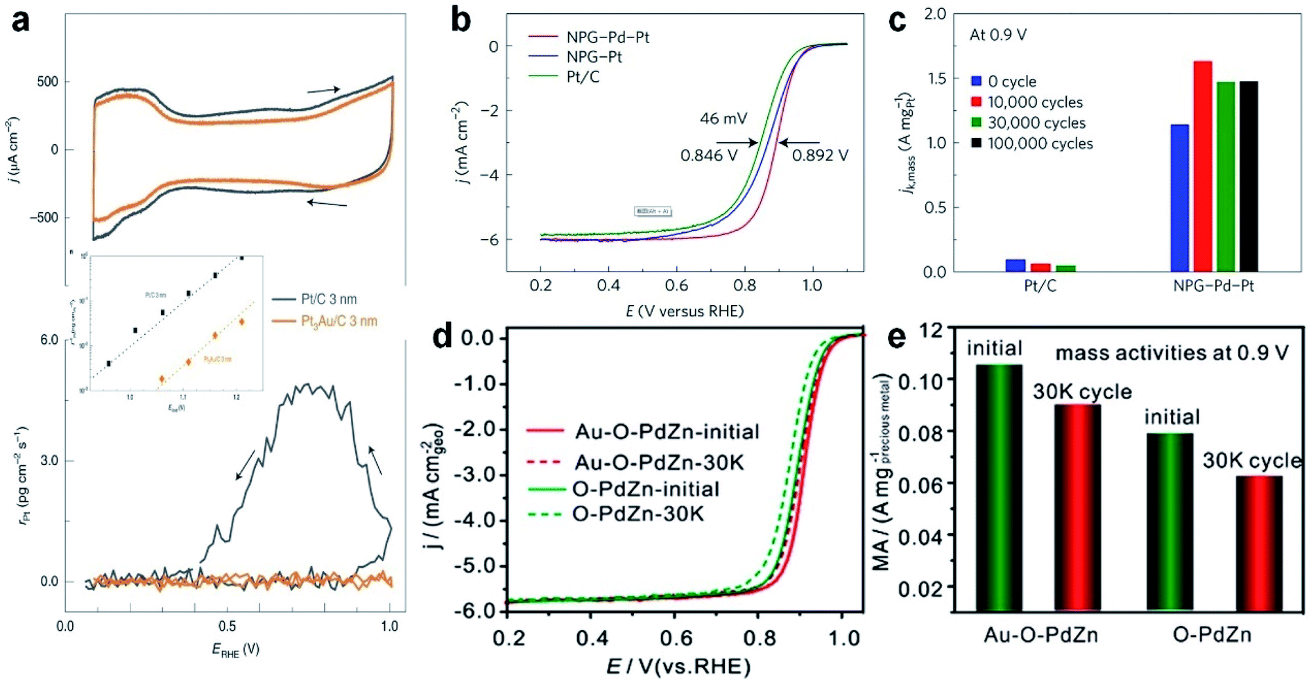 | ||
| Fig. 8 The electrocatalytic performance of Au-based nanoalloys towards the ORR. (a) CV curves (top panel) and the corresponding Pt dissolution plots (bottom panel) of Pt/C and Pt3Au/C in 0.1 M HClO4 solution (50 mV s−1, 25 °C and 100 rpm). Inset: the comparison of Pt dissolution at various positive potential limits for Pt/C and Pt3Au/C in 0.1 M HClO4 solution at 50 mV s−1. Reproduced with permission.177 Copyright 2020, Springer Nature. (b) Positive ORR polarization curves of commercial Pt/C, NPG–Pt and fresh NPG–Pd–Pt in O2-saturated 0.1 M HClO4 solution (10 mV s−1, 25 °C and 1600 rpm.) (c) Mass activity of Pt/C and NPG–Pd–Pt at 0.9 V (vs. RHE) at various stages of durability measurements. Reproduced with permission.33 Copyright 2017, Springer Nature. (d and e) ORR polarization curves (d) and the corresponding mass activity at 0.9 V (e) of O–PdZn and Au–O–PdZn catalysts before and after 30000 potential cycles. Reproduced with permission.180 Copyright 2019, American Chemical Society. | ||
To promote the synergistic effects between different metal elements, researchers have extended the ORR catalysts from bimetallic alloys to multi-metallic alloys. As a typical study, Li et al. reported a new type of electrocatalyst in which Pt–Pd nanoshells with a sub-nanometer thickness were coated on nano-porous Au (denoted as NPG–Pd–Pt).33 It was found that the half-wave potential of the NPG–Pd–Pt catalyst showed a positive shift of about 46 mV compared to that of commercial Pt/C in the ORR polarization curve (Fig. 8b), indicating its higher activity. As for cycling stability, the NPG–Pd–Pt catalyst showed an obvious increase of mass activity, i.e., 1.632 A mgPt−1 after 10000 cycles (Fig. 8c). Moreover, its performance after 100000 cycles remained almost the same as that after 30000 cycles, which indicates the excellent cycling stability. Delicate structural characterization revealed that the surface evolution of the NPG–Pd–Pt catalyst happened in the long-term cycling process and eventually a stable structure of the Pt–Pd–Au alloy was formed to achieve such a superior stability. Inspired by this work, core–shell NPs have also become a popular candidate for ORR electrocatalysts in the past few years.
In order to decrease the cost of ORR catalysts, researchers have also tried to combine other cheap transition metals (e.g., Ni, Cu, Co and Fe) with noble metals such as Au. For instance, Johnston et al. prepared bimetallic Au–Ni nanodendrites through one-pot electrochemical deposition and dealloying methods.178 The Au–Ni nanodendrites exhibited higher half-wave potential, excellent catalytic activity and good durability up to 5000 cycles in the ORR. It was proposed that the unique nanodendritic structure with the Au-rich surface and the electronic effect in Au–Ni nanodendrites are the main factors enhancing their ORR performance. In another study, Au–Cu alloy aerogels were also synthesized for the ORR.179 The presence of Cu would shift the d-band center of Au, which leads to more catalytically active sites and higher activity. Specifically, compared with commercial Pt/C, the SA and MA of Au–Cu alloy aerogels increased by 4.5 and 6.3 times, respectively. Apart from the aforementioned binary alloy catalysts, Wang et al. prepared a ternary alloy catalyst through incorporating Au into ordered intermetallic PdZn supported on carbon (denoted as Au–O–PdZn/C), and used it as a Pt-free ORR electrocatalyst.180 Compared to the control samples, the half-wave potential of Au–O–PdZn/C showed the most positive shift (50 mV), which only dropped by 6 mV after 30000 cycles. Meanwhile, the MA realized a high current density of 0.105 A mgAu+Pd−1 at 0.9 V, and only decreased by 9.5% after 30000 cycles (Fig. 8d and e). It was suggested that, Au atoms, which partially replace the original Pd or Zn atoms and are located on the surface or the inside of PdZn, should be responsible for enhancing the ORR activity and durability.
For improving the production of H2O2 in the ORR via the 2-electron pathway, numerous studies have been conducted by virtue of surface engineering of catalysts. By modulating the adsorption behaviors of O2 or *OOH on catalyst surfaces, a better performance towards H2O2 generation can be achieved. For example, Au is regarded as a promising electrocatalyst for H2O2 production because of its low over-potential and unique 2e-ORR on the (111) and (110) surfaces.181 However, the poor adsorption capability of O2 on Au limits its ORR activity.182 By rationally modulating the adsorption behavior of O2, Au can be transformed into an excellent 2e-ORR electrocatalyst by introducing other noble metal atoms such as Pd, Pt or Rh to its surface.183 The introduction of a moderate amount of other noble metals that can strongly interact with the O2 molecule is propitious to the adsorption of O2 while maintaining the end-on adsorption mode and inhibiting the O–O bonding cleavage owing to the inertness of Au, which will improve the 2e-ORR activity and maintain the selectivity as well. Considering the preferable adsorption ability of Ni and Pt to O2, Amal et al. introduced Ni and Pt to the surface of Au nanorods by epitaxial growth to generate Au–Ni core–shell nanorods and Au–Pt–Ni core-sandwich-shell nanorods, which exhibited higher activity and selectivity towards H2O2 production than pure Au nanorods.184 Apart from the O2 adsorption adjustment, the manipulation of the adsorption behavior of *OOH proves another route to enhance the 2e-ORR activity.185 As the key intermediate for H2O2 production, *OOH is supposed to be quickly released from the active site to undergo the following proton-coupled electron transfer. Therefore, materials that possess weak *OOH adsorption ability can also be employed to improve the H2O2 production. For instance, combining 4e-ORR metals such as Pt and Pd with other metals with a weak *OOH adsorption ability such as Hg is an efficient way to enhance the 2e-ORR performance.186
5.3. Hydrogen evolution reaction
Developing clean and renewable hydrogen energy, the most promising energy resource, has been considered as a viable strategy to liberate us from the extreme reliance on fossil fuels and enable us to maintain a sustainable future. To this end, using the HER, an important reaction that occurs at the cathode of water splitting devices, in the electrocatalytic process to generate H2 attracts broad attention due to the purity of the produced H2 and mild reaction conditions. The mechanism of the HER involves several steps that can be classified as the Volmer–Tafel (combination reaction) and Volmer–Heyrovsky mechanisms (ion + atom reaction).187 In the Volmer–Tafel mechanism, a proton first adsorbs onto the electrode and couples with an electron to generate an adsorbed hydrogen atom (Volmer reaction or discharge reaction). Then another proton undergoes the same process and is adsorbed onto the site near the previous hydrogen atom. In the end, the two adjacent adsorbed hydrogen atoms combine on the surface of the electrode to give H2. The difference in the other mechanism lies in that the second proton will directly couple with the first adsorbed hydrogen atom to form H2 with the second electron transfer. Based on the aforementioned HER mechanism, it is obvious that the discharge reaction, combination reaction and ion + atom reaction will all contribute to the overall reaction rate of the HER process, in which the rate-determining step can be determined by deriving the Tafel slopes.188 Therefore, by controlling the interaction ability of electrocatalysts with the key intermediates in the rate-determining step, the HER with high activity is supposed to be achieved.Up to now, many Au-based nanoalloys have been designed and shown comparable catalytic activity to Pt for the HER due to the synergistic effects between different metals. Table 4 shows the catalytic performance of different Au-based nanoalloys for the HER. For instance, Sun et al. prepared NiAu/Au core/shell NPs that exhibited Pt-like activity for the HER.36 Specifically, it was found that the HER activity of the Ni43Au57 nanoalloy can be greatly enhanced after continuous potential cycling from 0.6 to 1.0 V. After potential cycling, the surface Ni in Ni43Au57 NPs was leached away, leading to formation of NiAu/Au core/shell NPs. By using 0.5 M H2SO4 solution as the electrolyte, Ni43Au57 NPs showed a relatively low onset potential of about −70 mV (Fig. 9a). After over 5000 potential cycles, the onset potential of Ni43Au57 NPs was greatly decreased due to the formation of NiAu/Au core/shell NPs (Fig. 9b). Furthermore, after 10000 potential sweeps between −0.3 and 0.9 V, the NiAu/Au core/shell NPs exhibited no obvious decrease in HER activity, which is much superior to that of the commercial Pt/C catalyst (Fig. 9c). Considering the recombination of two adsorbed H atoms as the rate-determining step (based on the calculated Tafel slope), this unique NiAu/Au core/shell structure has the Pt-like activity and is even more stable than the Pt catalyst. Theoretical calculations indicated that the leaching of surface Ni decreases the coordination number of surface Au atoms, which could significantly increase the HER activity. In another study, Wang et al. synthesized multiply-twinned Au–Ag nanocrystals supported on reduced graphene oxide, which exhibited excellent HER activities in various pH environments, including acidic, neutral and basic electrolytes.189
| Catalysts | Electrolyte | E onset (mVRHE) | η 10 (mV) | Tafel slope (mV s−1) | Stability | Ref. |
|---|---|---|---|---|---|---|
| a E onset, onset potential; η10, overpotential at 10 mA cm−2; CSSSD, core–shell star-shaped decahedra; η, overpotential; rGO, reduced graphene oxide. | ||||||
| Au75Rh25 CSSSD | 0.5 M H2SO4 | — | 64.1 | 33.8 | η increases during 500 cycles (0–1.1 VRHE) | 232 |
| S-doped AuPbPt NWNs | 0.5 M H2SO4 | −2 | 12 | 17.7 | No obvious change of η10 after 5000 cycles (0–1.35 VRHE) | 220 |
| Au@Zn–Fe–C | 0.5 M H2SO4 | −80 | — | 130 | No obvious change of current density after 12 h at −0.15 VRHE | 233 |
| Au–Pd NPs/rGO | 0.5 M H2SO4 | ∼ −0.8 | — | 29 | Current density increases over 24 h at −0.7 VSCE | 234 |
| Au–Ag icosahedra/rGO | 0.5 M H2SO4 | ∼ −10 | — | 39 | Potential (at 25 mA cm–2) increases by 12 mV after 10000 cycles (−0.2–1.0 VRHE) |
189 |
| C–Ni43Au57 NPs | 0.5 M H2SO4 | ∼ −70 | — | 43 |
E
onset decreases to ∼ −7 mV after 10000 cycles (0.6–1.0 VRHE) |
36 |
| RuAu-0.2 SAA | 1 M KOH | — | 24 | 37 | η increases by ∼2 mV after 1000 cycles (−0.26–0.14 VRHE) | 135 |
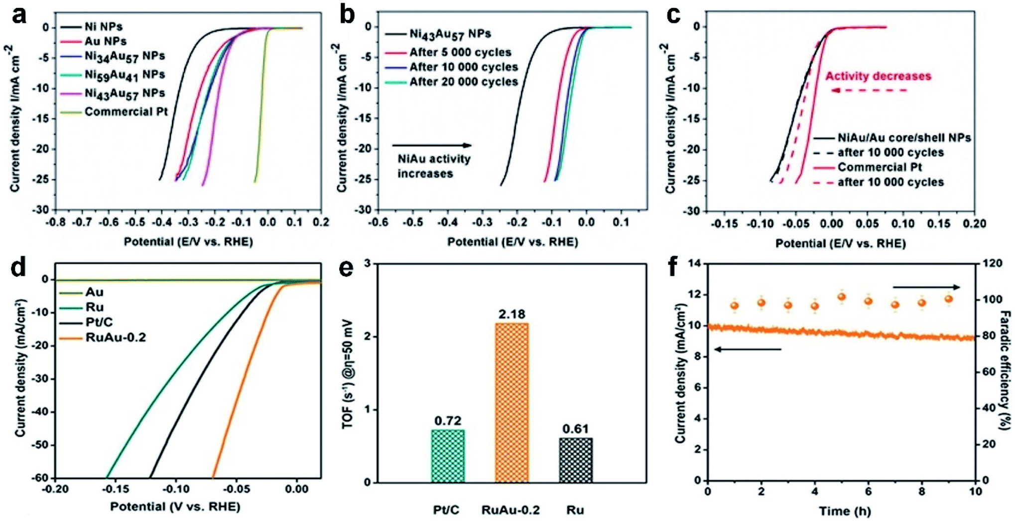 | ||
| Fig. 9 The electrocatalytic performance of Au-based nanoalloys towards the HER. (a–c) Linear sweep voltammetry (LSV) polarization curves of (a) different catalysts such as Ni NPs, Au NPs, NixAuy NPs and commercial Pt, (b) Ni43Au57 NPs before and after different numbers of potential cycles, and (c) NiAu/Au core/shell NPs and commercial Pt before and after 10000 potential cycles in 0.5 M H2SO4 solution. Reproduced with permission.36 Copyright 2015, American Chemical Society. (d) LSV polarization curves of Au, Ru, Pt/C and Ru/Au-0.2 at the scanning rate of 5 mV s−1. (e) TOF of Ru, Pt/C and Ru/Au-0.2 at the overpotential of 50 mV. (f) Chronoamperometric plot (left axis) and FE (right axis) of the RuAu SAA. Reproduced with permission.135 Copyright 2019, Wiley-VCH. | ||
The particle size is also closely related to the HER activity. The reduction of the catalyst size can significantly increase the specific surface area and expose more active sites, thereby increasing the catalytic activity. In particular, single-atom catalysts (SACs), isolated atoms that are well dispersed on supports, exhibit outstanding catalytic activity, selectivity and stability. As a typical study, Chen et al. synthesized Ru–Au bimetallic SAAs as HER catalysts and tested in 1 M KOH solution.135 The Ru–Au SAA exhibited a quite low overpotential of 24 mV at 10 mA cm−2, which is much lower compared to those of the Au SAC, Ru SAC and commercial Pt/C (Fig. 9d). The calculated turnover frequency (TOF) of the Ru–Au SAA at −50 mV reached up to 2.18 s−1, which is 3.0 and 3.6 times those of Pt/C and the Ru SAA, respectively (Fig. 9e). After the long-term stability test for 10 h, the Ru–Au SAA only showed a small decrease of 8% in current density, which further proved the excellent electrochemical stability of the Ru–Au SAA (Fig. 9f). In addition, during the stability test, the Faradaic yield remained 100%, indicating that the observed current was entirely attributed to the HER. Theoretical and experimental investigations suggested that the superior HER performance of the Ru–Au SAA is attributed to the relay catalysis, in which the Ru atom captures and splits water molecules and subsequently the Au atom adsorbs protons and facilitates the H2 production.
5.4. Oxygen evolution reaction
The OER plays a critical role in oxidizing water molecules (in acidic or neutral solution) and hydroxide (in alkaline solution) to produce O2 and rechargeable metal–air batteries as well. Due to the inherently sluggish kinetics, the rate of the OER will largely determine the practical application of water splitting and metal–air batteries.190 Therefore, developing highly active OER catalysts to reduce the energy barrier and thus improve the reaction kinetics is key for a number of renewable energy technologies. Besides the noble metal oxides, such as ruthenium oxides and iridium oxides, a variety of Au-based nanoalloys with high catalytic activity and stability towards the OER have also been developed in recent years. Table 5 shows the catalytic performance of different Au-based nanoalloys for the OER.| Catalysts | Electrolyte | Overpotential (mV) | Tafel slope (mV s−1) | Stability | Ref. |
|---|---|---|---|---|---|
| Au0.89Fe0.11 NPs | 1 M KOH | ∼800 (at 10 mA cm−2) | 46 | 63% loss of current after 1000 cycles (0.57 to 1.87 VRHE) | 141 |
| Au–Ru branched NPs | 0.1 M HClO4 | 220 (at 10 mA cm−2) | 62 | 67% loss of activity after 1000 cycles at 1.46 VRHE | 235 |
| NiFe LDH@Au/Ni foam | 30 wt% KOH | 221 (at 50 mA cm−2) | 60.8 | Overpotential increases by 15 mV after 5000 cycles | 236 |
| AuCuCo NPs | 0.1 M KOH | 596 (at 10 mA cm−2) | 65.0 | <20% loss of relative current after 4 h at 0.765 VRHE | 192 |
Combining Au with some highly active metal components is an important way to prepare high-performance OER catalysts. As a representative study, Lu et al. synthesized PtAu NPs as the cathode electrocatalyst for rechargeable Li–O2 batteries, in which the OER kinetics can be significantly enhanced and the charge voltage could be effectively reduced to 3.4 V in 0.5 M H2SO4.191 Recently, to further decrease the cost of preparing efficient OER catalysts, great efforts have been devoted to introducing earth-abundant metal elements in Au-based nanoalloys. For example, Yang et al. synthesized self-supported AuCuCo nanostructures and evaluated their OER activity in 0.1 M KOH solution.192 Owing to the special 3D structure, electronic structure variation of Au via alloying and the presence of abundant twin structures, the OER activity of AuCuCo nanostructures was comparable with that of commercial Pt/C and IrO2/C catalysts. Moreover, AuCuCo nanostructures showed better catalytic durability than both Pt/C and IrO2/C.
Besides Cu and Co, alloying other early transition metals such as Fe with Au can also increase their catalytic activity towards the OER. For instance, Alessandri et al. prepared Au–Fe nanoalloys with a large content of Fe (up to 11 at%) using LALT and tested in 1 M KOH.141 The cyclic voltammetry (CV) results showed that Au0.89Fe0.11 NPs exhibited the highest OER activity (Fig. 10a), which was much better than that of Au and FeOx NPs. Notably, at a current density of 10 mA cm−2, Au0.89Fe0.11 NPs showed the lowest overpotential of about 0.8 V, in comparison with Au NPs, FeOx NPs and their physical mixture (Fig. 10b). Meanwhile, the OER onset potential of Au0.89Fe0.11 NPs was also remarkably shifted to a lower potential compared to those of Au NPs, FeOx NPs and their physical mixture (Fig. 10c). Furthermore, at a potential of 1.82 V (vs. RHE), the Au0.89Fe0.11 nanoalloy exhibited a current density of ∼4 mA cm−2, which was around 23, 13 and 30 times larger than those of Au NPs, FeOx NPs and their physical mixture, respectively (Fig. 10d). It was suggested that the enhanced OER performance of Au0.89Fe0.11 NPs could be attributed to the strong chemical and electronic interactions between Au and Fe atoms.
 | ||
| Fig. 10 The electrocatalytic performance of Au-based nanoalloys towards the OER. (a) CV curves of AuxFey nanoalloys, Au NPs, FeOx NPs, and the mixture of Au and FeOx NPs in 1 M KOH. (b) Comparison of the overpotentials needed to obtain a current density of 10 mA cm−2 for different nanocatalysts. (c) Zoom of CV curves within the potential range of 1.40–1.87 V (vs. RHE). (d) Comparison of the current densities obtained at a potential of 1.82 V (vs. RHE) for different nanocatalysts. ITO is short for indium tin oxide. Reproduced with permission.141 Copyright 2017, Wiley-VCH. | ||
5.5. Small organic molecule oxidation reaction
The electrochemical oxidation reactions of small organic molecules play an important role in the development of environmentally-friendly and economic fuel cells, which can efficiently convert chemical energy into electric energy and enable next-generation transport tools.193–195 The aforementioned small organic molecules, such as methanol, ethanol, and formic acid, possess high energy density and facile on-board storage. Typically, H2O and CO2 are the main final products of the small organic molecule oxidation reactions, in which a 2-electron transfer, 6-electron transfer, and 12-electron transfer occur for the formic acid oxidation reaction (FAOR),196 methanol oxidation reaction (MOR),197 and ethanol oxidation reaction (EOR),198 respectively. Pt nanostructures show high activity towards small organic molecule oxidation reactions. However, the intermediate reactions normally involve the formation of CO, which can poison the Pt catalysts due to the particularly strong interaction between CO and Pt atoms. As the CO adsorption ability of Au is relatively weak, introducing Au into Pt nanostructures could be an effective way to disrupt the CO bonding and thus retard the poisoning effect of CO to Pt. For example, when Pt–Au alloy NPs were used for the MOR, intermediate products were preferably oxidized to CO2 rather than CO, increasing the catalyst activity and durability as well.199 Therefore, Au-based nanoalloys with special compositions and nanostructures have been frequently employed as efficient catalysts with superior activity and excellent stability for small organic molecule oxidation reactions.200The combination of Au with other noble metals is an efficient strategy to prepare high-performance electrocatalysts for the oxidation of small organic molecules. Recently, Wang et al. synthesized PdAu/Pt trimetallic NPs supported on carbon nanotubes (denoted as CNTs-PdAu/Pt) and evaluated their catalytic performance towards the MOR in alkaline electrolyte.201 It was found that within 500 CV cycles, the CNTs-PdAu/Pt catalyst showed the highest mass activity (refer to Pt) and stability (the retention rate is 76%) in comparison with CNTs-Pd/Pt, CNTs-Au/Pt and commercial Pt/C catalysts. The enhanced MOR performance of the CNTs-PdAu/Pt catalyst was attributed to the synergistic effects between Au, Pd and Pt. Specifically, alloying Pd and Au with Pt generated numerous small Pt ensembles that were catalytically active for the MOR. Alternatively, the addition of Au could stabilize Pt from surface oxidation. Furthermore, introducing Pd might induce remarkable electron transfer from Pd to Pt, which could lead to the downshift of the Pt d-band center and thus decrease the interaction between Pt and poisoning species such as CO.
Besides noble metals, alloying Au with other early transition metals could be another effective and economic way to improve the electrocatalytic performance towards small organic molecule oxidation. As a typical study, Nugraha et al. prepared mesoporous Au41Cu46Ni13 ternary alloy films with different compositions towards the MOR.120 It was observed that the mesoporous ternary alloy film with a composition of Au41Cu46Ni13 demonstrated superior catalytic activity (current density: 3.8 mA cm−2; mass activity: 1.7 A mg−1) and excellent stability (no obvious changes in both catalytic activity and the structure were observed after working for 1200 s at 0.65 V (vs. Ag/AgCl)) as well.
5.6. CO oxidation reaction
In modern society, fast public and private transport produces large amounts of automobile exhaust gases, such as CO, which have already become the culprit that leads to many environmental and health problems. However, fixing and transforming CO into non-toxic gases or useful fuels/chemicals is relatively difficult compared with the CO2RR because it would poison most noble metal-based catalysts and thus significantly reduce the working life. Therefore, how to perform efficient CO oxidation has become a critical scientific issue receiving wide research interest.Au is particularly active in catalyzing CO oxidation.22 But in order to further increase the catalytic stability and/or activity of Au, binary or ternary Au-based nanoalloys have been extensively investigated. For example, Han et al. synthesized a series of binary Pd–Au nanoalloys that showed excellent catalytic performance towards CO oxidation.45 When the atomic ratio of Pd:Au was 4:1, optimum catalytic activity was obtained among all Pd–Au nanoalloys (Fig. 11a). The activation energy of Pd4Au1 is 65.6 kJ mol−1, which is much smaller than that of the other Pd–Au nanoalloys (Fig. 11b). Significantly, the cycling stability of Pd4Au1 is significantly better compared to that of pure Au (Fig. 11c). Specifically, in an ideal exhaust gas at 353 K for 10 h, the pure Au catalyst lost 50% of its catalytic performance while only a 5% loss was found for the Pd4Au1 nanoalloy. Experimental observations suggested that the superior catalytic performance of Pd–Au nanoalloys could arise from the presence of abundant surface defects (e.g., metal vacancies) as well as alloying-induced electronic structure modifications of Au and Pd atoms.
 | ||
| Fig. 11 The electrocatalytic performance of Au-based nanoalloys towards the CO oxidation reaction. (a and b) Temperature-dependent CO oxidation (a) and Arrhenius plots of the reaction rate (b) of Au, Pd and PdxAuy alloys. (c) Time-dependent CO oxidation on Au/SiO2 and Pd4Au1/SiO2 in the ideal exhaust gas (filled symbol) or the simulated exhaust gas (hollow symbol). Reproduced with permission.45 Copyright 2010, American Chemical Society. (d) Temperature-dependent CO oxidation on LDHs, Cu/LDHs, Au/LDHs and AuxCuy/LDHs. (e) Arrhenius plots of LDHs, Au/LDHs and AuxCuy/LDHs. (f) CO conversion versus time for LDHs, Au/LDHs and Au2M1/LDHs (M = Cu, Ni, Pt). Reproduced with permission.204 Copyright 2020, Elsevier. | ||
Catalyst supports can also greatly affect the catalytic CO oxidation performance of Au-based nanoalloys through the well-known metal–support interaction.202 Recently, researchers have tried to load Au-based nanoalloys on different supports to achieve highly efficient and stable catalysts for CO oxidation. For instance, Li et al. used TiO2 as the support for Pt–Au binary nanoalloys to improve the catalytic CO oxidation performance.203 Specifically, TiO2 can facilitate the dispersion and restrict the growth/aggregation of Pt–Au NPs, which allows sufficient and stable active sites for CO oxidation. In another study, Xia et al. employed layered double hydroxides (LDHs) as the support for a variety of binary Au-M (M = Ni, Cu, Pt) nanoalloys.204 It was found that the Au2Cu1 nanoalloy supported on LDHs (denoted as Au2Cu1/LDHs) showed the highest catalytic activity and lowest activation energy among various Au–M/LDH nanoalloys, Au/LDHs and LDHs (Fig. 11d and e). Moreover, after 48 h of continuous catalytic reaction, the CO conversion rate of all catalysts decreased slightly, and Au2Cu1/LDHs remained to be the optimum catalyst (Fig. 11f). In addition, Au2Cu1/LDHs also demonstrated a very good recyclability for CO oxidation, showing no obvious deactivation after three cycles (3 h per cycle). This work suggested that LDHs are a kind of stable, highly active and low-cost supporting material for Au-based nanoalloys towards the CO oxidation reaction.
5.7. Typical heterogeneous catalytic reactions in chemical engineering
Besides the aforementioned catalytic reactions, Au-based nanoalloys can also be used for many other heterogeneous catalytic reactions in chemical engineering, such as aerobic oxidation and hydrogenation of organic molecules. Several representative studies will be introduced here to demonstrate the application potential of Au-based nanoalloys in these fields.Although glycerol (GLY) is a by-product during the industrial production of biomass fuels, various value-added chemicals can be generated through the selective aerobic oxidation of GLY. Thus, how to facilitate GLY conversion and improve the selectivity to specific chemicals rather than the overoxidation products (e.g., CO2) are critically important. In this regard, Ebitani et al. synthesized Pt60Au40 alloy NPs supported on hydrotalcites (denoted as Pt60Au40–starch/HT) and explored the catalytic performance of GLY oxidation in an alkali-free aqueous solution.205 The major product of GLY oxidation is glyceric acid (GA) with a high selectivity of 87% at the reaction time of 1 h, and the GA selectivity can be maintained over 70% after reacting for 10 h (Fig. 12a). During the recycling measurement, although the catalytic activity of Pt60Au40–starch/HT slightly decreased, the high selectivity towards GA production was maintained (Fig. 12b). Experimental results indicated that the electronic and geometric modifications of Pt active sites by neighboring Au atoms and surface starch ligand result in the improvement of both activity and selectivity.
 | ||
| Fig. 12 The catalytic performance of Au-based nanoalloys towards typical heterogeneous catalytic reactions in chemical engineering. (a) GLY conversion, product yield and GA selectivity in GLY oxidation catalysed by Pt60Au40–starch/HT. (b) Recycling of the Pt60Au–starch/HT catalyst towards GLY oxidation. Reproduced with permission.205 Copyright 2013, American Chemical Society. (c) TOF plots for the catalytic cyclohexene hydrogenation on SiO2-supported Au, Pd and PdxAu100−x NPs. (d and e) Comparison of the catalytic hydrogenation activity of PdxAu100−x NPs that are (d) obtained with two different synthetic methods or (e) supported on different substrates. Reproduced with permission.206 Copyright 2016, American Chemical Society. | ||
Recently, vapor-phase catalytic hydrogenation of cyclohexene by PVP-capped PdxAu100−x NPs with various compositions was studied by Humphrey et al.206 It was found that Pd59Au41 NPs showed the highest catalytic cyclohexene hydrogenation activity among various PdxAu100−x NPs, Pd NPs and Au NPs (Fig. 12c). The steady-state TOF was usually reached after 4–5 h. Interestingly, the preparation method of PdxAu100−x NPs can also greatly affect their catalytic activity towards cyclohexene hydrogenation (Fig. 12d). Specifically, PdxAu100−x NPs obtained under microwave irradiation (μwI) tend to possess much higher catalytic hydrogenation activity than those obtained with conventional heating (CvH). Moreover, the steady-state TOF of PdxAu100−x (i.e., close to Pd60Au40) catalysts supported on different substrates showed no obvious differences (Fig. 12e), indicating that the catalyst substrate is not the key factor here. Theoretical calculations suggested that long range electronic effects and local ensemble effects in the PdxAu100−x alloy could contribute to the enhanced catalytic hydrogenation activity.
6. Conclusions and perspectives
In summary, we have briefly introduced the general synthetic methods as well as the typical catalytic applications of Au-based nanoalloys. In Au-based nanoalloys, the electronic structures are usually heavily modulated by Au and the other metal components, which could significantly alter their catalytic performance. Generally, Au plays two main roles in Au-based nanoalloys. On the one hand, Au is able to regulate the electronic structure of the entire nanoalloy as an active component, increasing the catalytic activity and selectivity. On the other hand, Au can act as a stable and homogeneous substance to strongly bind with other highly active metal components, which enhances the resistance against external poisoning and internal structural degradation, thereby improving the catalytic durability of nanoalloys. Based on previous catalytic studies, Au-based nanoalloys containing Cu are promising catalysts for the CO2RR, while the combination of Au and Pt/Pd can remarkably enhance the stability of catalysts towards the ORR. As for the HER and OER, forming Au-based nanoalloys with earth-abundant metals such as Ni, Fe and Co is a prospective strategy to further boost the catalytic performance.At present, it is widely accepted that the key factors affecting the catalytic performances of Au-based nanoalloys include composition, size, shape, crystal phase, support and so on. Therefore, the ultimate goal is to achieve precise control of the aforementioned factors through facile regulation methods and reveal the general structure/component-performance relationships, which will direct the synthesis of ideal Au-based nanoalloys with favorable features for a range of catalytic reactions. Although the studies on Au-based nanoalloys have obtained notable progress, there are still some challenges needed to be overcome in this research direction. In general, current investigations on Au-based nanoalloys are still in the initial stage, mainly focusing on their composition design and morphology control. In the future, more attention should be paid to how to precisely control the arrangement of different metal elements in alloys at the atomic scale, and then synthesize catalysts with desirable atomic and electronic structures. Considering that recent investigations have proven the crystal phase-dependent catalytic activity and selectivity in metal and alloy-based nanomaterials, synthesis of Au-based nanoalloys with different, unusual and even novel crystal phases is of great significance for future studies.65,88,207–211 Crystal phase control could be a promising strategy for further improving the catalytic performance of Au-based nanoalloys.
Furthermore, more advanced synthetic technologies are expected to be developed for Au-based nanoalloys with new microstructures and optimum compositions. At present, the effective synthetic methods for Au-based nanoalloys mainly concentrated on the co-reduction of metal precursors, which shows the advantages of low cost and high yield and the disadvantages of limited metal precursors that can be simultaneously reduced. Comparatively, few other effective synthetic methods are widely utilized to produce Au-based nanoalloys. Despite several unconventional strategies, such as polymer nanoreactor mediated synthesis and the cast cum cryo-milling process, have proven to be promising, their low yield cannot meet the requirements of large-scale industrial production. Therefore, it is quite important and urgent to promote the current or even develop novel synthetic strategies to precisely modulate the microstructure and composition of Au-based nanoalloys while enabling large-scale productivity to satisfy the large quantity demand in a wide range of practical applications including catalysis.
Conflicts of interest
The authors declare no competing financial interest.Acknowledgements
Z. F. acknowledges the support from ITC via the Hong Kong Branch of National Precious Metals Material Engineering Research Center (NPMM), the Start-Up Grant (project no. 7200651) and Grants (project no. 9610480, 9680301 and 7005512) from the City University of Hong Kong, and the Grant (project no. 22005258) from the National Natural Science Foundation of China.Notes and references
- Z. Tong, Y. Chen, A. Malkawi, Z. Liu and R. B. Freeman, Appl. Energy, 2016, 179, 660–668 CrossRef.
- K. Zaman and M. A.-e. Moemen, Renewable Sustainable Energy Rev., 2017, 74, 1119–1130 CrossRef.
- Z. Zoundi, Renewable Sustainable Energy Rev., 2017, 72, 1067–1075 CrossRef CAS.
- J. H. Williams, A. DeBenedictis, R. Ghanadan, A. Mahone, J. Moore, W. R. Morrow III, S. Price and M. S. Torn, Science, 2012, 335, 53–59 CrossRef CAS PubMed.
- Y.-M. Wang, A. D. Lackner and F. D. Toste, Acc. Chem. Res., 2014, 47, 889–901 CrossRef CAS PubMed.
- P. Buchwalter, J. Rose and P. Braunstein, Chem. Rev., 2015, 115, 28–126 CrossRef CAS PubMed.
- F. Zaera, Chem. Soc. Rev., 2013, 42, 2746–2762 RSC.
- Z.-Y. Zhou, N. Tian, J.-T. Li, I. Broadwell and S.-G. Sun, Chem. Soc. Rev., 2011, 40, 4167–4185 RSC.
- B. Wu and N. Zheng, Nano Today, 2013, 8, 168–197 CrossRef CAS.
- K. D. Gilroy, A. Ruditskiy, H.-C. Peng, D. Qin and Y. Xia, Chem. Rev., 2016, 116, 10414–10472 CrossRef CAS PubMed.
- X. Feng, K. Jiang, S. Fan and M. W. Kanan, J. Am. Chem. Soc., 2015, 137, 4606–4609 CrossRef CAS PubMed.
- A. S. Hall, Y. Yoon, A. Wuttig and Y. Surendranath, J. Am. Chem. Soc., 2015, 137, 14834–14837 CrossRef CAS PubMed.
- M. Liu, Y. Pang, B. Zhang, P. De Luna, O. Voznyy, J. Xu, X. Zheng, C. T. Dinh, F. Fan, C. Cao, F. P. G. de Arquer, T. S. Safaei, A. Mepham, A. Klinkova, E. Kumacheva, T. Filleter, D. Sinton, S. O. Kelley and E. H. Sargent, Nature, 2016, 537, 382–386 CrossRef CAS PubMed.
- W. Zhu, Y.-J. Zhang, H. Zhang, H. Lv, Q. Li, R. Michalsky, A. A. Peterson and S. Sun, J. Am. Chem. Soc., 2014, 136, 16132–16135 CrossRef CAS PubMed.
- H. Schmidbaur, Angew. Chem., Int. Ed., 1976, 15, 728–740 CrossRef.
- A. S. K. Hashmi and G. J. Hutchings, Angew. Chem., Int. Ed., 2006, 45, 7896–7936 CrossRef PubMed.
- D. J. Gorin, B. D. Sherry and F. D. Toste, Chem. Rev., 2008, 108, 3351–3378 CrossRef CAS PubMed.
- A. Corma and H. Garcia, Chem. Soc. Rev., 2008, 37, 2096–2126 RSC.
- M. S. Chen and D. W. Goodman, Science, 2004, 306, 252 CrossRef CAS PubMed.
- G. C. Bond, Gold Bull., 1972, 5, 11–13 CrossRef CAS.
- G. C. Bond, P. A. Sermon, G. Webb, D. A. Buchanan and P. B. Wells, J. Chem. Soc., Chem. Commun., 1973, 13, 444b–445 RSC.
- M. Haruta, T. Kobayashi, H. Sano and N. Yamada, Chem. Lett., 1987, 16, 405–408 CrossRef.
- A. Wittstock, V. Zielasek, J. Biener, C. M. Friend and M. Bäumer, Science, 2010, 327, 319–322 CrossRef CAS PubMed.
- Y. Chen, C. W. Li and M. W. Kanan, J. Am. Chem. Soc., 2012, 134, 19969–19972 CrossRef CAS PubMed.
- G. Li and R. Jin, Acc. Chem. Res., 2013, 46, 1749–1758 CrossRef CAS PubMed.
- M. Rudolph and A. S. K. Hashmi, Chem. Soc. Rev., 2012, 41, 2448–2462 RSC.
- X.-F. Yang, A. Wang, B. Qiao, J. Li, J. Liu and T. Zhang, Acc. Chem. Res., 2013, 46, 1740–1748 CrossRef CAS PubMed.
- J. Zeng, Q. Zhang, J. Chen and Y. Xia, Nano Lett., 2010, 10, 30–35 CrossRef CAS PubMed.
- B. N. Zope, D. D. Hibbitts, M. Neurock and R. J. Davis, Science, 2010, 330, 74–78 CrossRef CAS PubMed.
- Z. Fan, M. Bosman, Z. Huang, Y. Chen, C. Ling, L. Wu, Y. A. Akimov, R. Laskowski, B. Chen, P. Ercius, J. Zhang, X. Qi, M. H. Goh, Y. Ge, Z. Zhang, W. Niu, J. Wang, H. Zheng and H. Zhang, Nat. Commun., 2020, 11, 3293 CrossRef CAS PubMed.
- T. Ishida, H. Koga, M. Okumura and M. Haruta, Chem. Rec., 2016, 16, 2278–2293 CrossRef CAS PubMed.
- L. Zhang, Z. Xie and J. Gong, Chem. Soc. Rev., 2016, 45, 3916–3934 RSC.
- J. Li, H.-M. Yin, X.-B. Li, E. Okunishi, Y.-L. Shen, J. He, Z.-K. Tang, W.-X. Wang, E. Yücelen, C. Li, Y. Gong, L. Gu, S. Miao, L.-M. Liu, J. Luo and Y. Ding, Nat. Energy, 2017, 2, 17111 CrossRef CAS.
- Q. Zhang, K. Kusada, D. Wu, T. Yamamoto, T. Toriyama, S. Matsumura, S. Kawaguchi, Y. Kubota and H. Kitagawa, Nat. Commun., 2018, 9, 510 CrossRef PubMed.
- X. Zhang, S. Han, B. Zhu, G. Zhang, X. Li, Y. Gao, Z. Wu, B. Yang, Y. Liu, W. Baaziz, O. Ersen, M. Gu, J. T. Miller and W. Liu, Nat Catal., 2020, 3, 411–417 CrossRef CAS.
- H. Lv, Z. Xi, Z. Chen, S. Guo, Y. Yu, W. Zhu, Q. Li, X. Zhang, M. Pan, G. Lu, S. Mu and S. Sun, J. Am. Chem. Soc., 2015, 137, 5859–5862 CrossRef CAS PubMed.
- H. Fang, J. Yang, M. Wen and Q. Wu, Adv. Mater., 2018, 30, 1705698 CrossRef PubMed.
- Y. Xia, Y. Xiong, B. Lim and S. E. Skrabalak, Angew. Chem., Int. Ed., 2009, 48, 60–103 CrossRef CAS PubMed.
- C. Suryanarayana, Prog. Mater. Sci., 2001, 46, 1–184 CrossRef CAS.
- V. R. Stamenkovic, B. Fowler, B. S. Mun, G. Wang, P. N. Ross, C. A. Lucas and N. M. Marković, Science, 2007, 315, 493–497 CrossRef CAS PubMed.
- R. Ryoo, J. Kim, C. Jo, S. W. Han, J.-C. Kim, H. Park, J. Han, H. S. Shin and J. W. Shin, Nature, 2020, 585, 221–224 CrossRef CAS PubMed.
- F. Yang, J. Ye, Q. Yuan, X. Yang, Z. Xie, F. Zhao, Z. Zhou, L. Gu and X. Wang, Adv. Funct. Mater., 2020, 30, 1908235 CrossRef CAS.
- J. Kleis, J. Greeley, N. A. Romero, V. A. Morozov, H. Falsig, A. H. Larsen, J. Lu, J. J. Mortensen, M. Dułak, K. S. Thygesen, J. K. Nørskov and K. W. Jacobsen, Catal. Lett., 2011, 141, 1067–1071 CrossRef CAS.
- L. Li, A. H. Larsen, N. A. Romero, V. A. Morozov, C. Glinsvad, F. Abild-Pedersen, J. Greeley, K. W. Jacobsen and J. K. Nørskov, J. Phys. Chem. Lett., 2013, 4, 222–226 CrossRef CAS PubMed.
- J. Xu, T. White, P. Li, C. He, J. Yu, W. Yuan and Y.-F. Han, J. Am. Chem. Soc., 2010, 132, 10398–10406 CrossRef CAS PubMed.
- J. Wang, H. Zhu, D. Yu, J. Chen, J. Chen, M. Zhang, L. Wang and M. Du, ACS Appl. Mater. Interfaces, 2017, 9, 19756–19765 CrossRef CAS PubMed.
- J. B. Xu, T. S. Zhao, W. W. Yang and S. Y. Shen, Int. J. Hydrogen Energy, 2010, 35, 8699–8706 CrossRef CAS.
- N. E. Motl, E. Ewusi-Annan, I. T. Sines, L. Jensen and R. E. Schaak, J. Phys. Chem. C, 2010, 114, 19263–19269 CrossRef CAS.
- F. Gao and D. W. Goodman, Chem. Soc. Rev., 2012, 41, 8009–8020 RSC.
- P. Liu and J. K. Nørskov, Phys. Chem. Chem. Phys., 2001, 3, 3814–3818 RSC.
- F. Gao, Y. Wang and D. W. Goodman, J. Am. Chem. Soc., 2009, 131, 5734–5735 CrossRef CAS PubMed.
- Y. Wang, L. Cao, N. J. Libretto, X. Li, C. Li, Y. Wan, C. He, J. Lee, J. Gregg, H. Zong, D. Su, J. T. Miller, T. Mueller and C. Wang, J. Am. Chem. Soc., 2019, 141, 16635–16642 CrossRef CAS PubMed.
- C. W. Yi, K. Luo, T. Wei and D. W. Goodman, J. Phys. Chem. B, 2005, 109, 18535–18540 CrossRef CAS PubMed.
- N. Yahya, S. K. Kamarudin, N. A. Karim, S. Basri and A. M. Zanoodin, Nanoscale Res. Lett., 2019, 14, 52 CrossRef CAS PubMed.
- J. Long, H. Liu, S. Wu, S. Liao and Y. Li, ACS Catal., 2013, 3, 647–654 CrossRef CAS.
- A. Bhatia and D. Thornton, Phys. Rev. B: Solid State, 1970, 2, 3004–3012 CrossRef.
- C. J. Kiely, J. Fink, J. G. Zheng, M. Brust, D. Bethell and D. J. Schiffrin, Adv. Mater., 2000, 12, 640–643 CrossRef CAS.
- P. Buchwalter, J. Rosé and P. Braunstein, Chem. Rev., 2015, 115, 28–126 CrossRef CAS PubMed.
- R. Ferrando, J. Jellinek and R. L. Johnston, Chem. Rev., 2008, 108, 845–910 CrossRef CAS PubMed.
- K. Tiwari, M. Manolata Devi, K. Biswas and K. Chattopadhyay, Prog. Mater. Sci., 2021 DOI:10.1016/j.pmatsci.2021.100794.
- M. Bon, N. Ahmad, R. Erni and D. Passerone, J. Chem. Phys., 2019, 151, 064105 CrossRef.
- Z. Fan, X. Huang, Y. Han, M. Bosman, Q. Wang, Y. Zhu, Q. Liu, B. Li, Z. Zeng, J. Wu, W. Shi, S. Li, C. L. Gan and H. Zhang, Nat. Commun., 2015, 6, 6571 CrossRef CAS PubMed.
- Z. Fan, Y. Zhu, X. Huang, Y. Han, Q. Wang, Q. Liu, Y. Huang, C. L. Gan and H. Zhang, Angew. Chem., Int. Ed., 2015, 54, 5672–5676 CrossRef CAS PubMed.
- Z. Fan, M. Bosman, X. Huang, D. Huang, Y. Yu, K. P. Ong, Y. A. Akimov, L. Wu, B. Li, J. Wu, Y. Huang, Q. Liu, C. Eng Png, C. Lip Gan, P. Yang and H. Zhang, Nat. Commun., 2015, 6, 7684 CrossRef CAS PubMed.
- Y. Chen, Z. Lai, X. Zhang, Z. Fan, Q. He, C. Tan and H. Zhang, Nat. Rev. Chem., 2020, 4, 243–256 CrossRef CAS.
- Z. Fan and H. Zhang, Acc. Chem. Res., 2016, 49, 2841–2850 CrossRef CAS PubMed.
- Z. Fan, Z. Luo, X. Huang, B. Li, Y. Chen, J. Wang, Y. Hu and H. Zhang, J. Am. Chem. Soc., 2016, 138, 1414–1419 CrossRef CAS PubMed.
- Z. Fan, Z. Luo, Y. Chen, J. Wang, B. Li, Y. Zong and H. Zhang, Small, 2016, 12, 3908–3913 CrossRef CAS PubMed.
- Z. Fan, X. Zhang, J. Yang, X.-J. Wu, Z. Liu, W. Huang and H. Zhang, J. Am. Chem. Soc., 2015, 137, 10910–10913 CrossRef CAS PubMed.
- Z. Fan, X. Huang, C. Tan and H. Zhang, Chem. Sci., 2015, 6, 95–111 RSC.
- S. Mejía-Rosales, A. Ponce and M. José–Yacamán, in Nanoalloys, ed. F. Calvo, Elsevier, Oxford, 2013, pp. 113–145 Search PubMed.
- A. A. Herzing, M. Watanabe, J. K. Edwards, M. Conte, Z.-R. Tang, G. J. Hutchings and C. J. Kiely, Faraday Discuss., 2008, 138, 337–351 RSC.
- R. Ferrando, in Front. Nanosci., ed. R. Ferrando, Elsevier, 2016, vol. 10, pp. 47–74 Search PubMed.
- R. L. Johnston, in Front. Nanosci., ed. R. L. Johnston and J. P. Wilcoxon, Elsevier, 2012, vol. 3, pp. 1–42 Search PubMed.
- P. Samorì, J. Mater. Chem., 2004, 14, 1353–1366 RSC.
- A. J. Renouprez, K. Lebas, G. Bergeret, J. L. Rousset and P. Delichère, in Stud. Surf. Sci. Catal., ed. J. W. Hightower, W. Nicholas Delgass, E. Iglesia and A. T. Bell, Elsevier, 1996, vol. 101, pp. 1105–1114 Search PubMed.
- J. R. Levine, J. B. Cohen, Y. W. Chung and P. Georgopoulos, J. Appl. Crystallogr., 1989, 22, 528–532 CrossRef CAS.
- A. R. Denton and N. W. Ashcroft, Phys. Rev. A, 1991, 43, 3161–3164 CrossRef CAS PubMed.
- P. M. Voyles, D. A. Muller, J. L. Grazul, P. H. Citrin and H. J. L. Gossmann, Nature, 2002, 416, 826–829 CrossRef CAS PubMed.
- E. Duval, A. Boukenter and B. Champagnon, Phys. Rev. Lett., 1986, 56, 2052–2055 CrossRef CAS PubMed.
- J. L. Rousset, F. J. Cadete Santos Aires, B. R. Sekhar, P. Mélinon, B. Prevel and M. Pellarin, J. Phys. Chem. B, 2000, 104, 5430–5435 CrossRef CAS.
- L. E. Marbella and J. E. Millstone, Chem. Mater., 2015, 27, 2721–2739 CrossRef CAS.
- N. A. Khan, A. Uhl, S. Shaikhutdinov and H. J. Freund, Surf. Sci., 2006, 600, 1849–1853 CrossRef CAS.
- K. Hoshino, T. Naganuma, K. Watanabe, Y. Konishi, A. Nakajima and K. Kaya, Chem. Phys. Lett., 1995, 239, 369–372 CrossRef CAS.
- A. Pramann, K. Koyasu, A. Nakajima and K. Kaya, J. Phys. Chem. A, 2002, 106, 2483–2488 CrossRef CAS.
- N. Toshima and T. Yonezawa, New J. Chem., 1998, 22, 1179–1201 RSC.
- A. E. Russell and A. Rose, Chem. Rev., 2004, 104, 4613–4636 CrossRef CAS PubMed.
- Z. Fan and H. Zhang, Chem. Soc. Rev., 2016, 45, 63–82 RSC.
- Y. Chen, Z. Fan, Z. Zhang, W. Niu, C. Li, N. Yang, B. Chen and H. Zhang, Chem. Rev., 2018, 118, 6409–6455 CrossRef CAS PubMed.
- Z. Fan, X. Huang, Y. Chen, W. Huang and H. Zhang, Nat. Protoc., 2017, 12, 2367–2376 CrossRef CAS PubMed.
- Z. Fan, Y. Chen, Y. Zhu, J. Wang, B. Li, Y. Zong, Y. Han and H. Zhang, Chem. Sci., 2017, 8, 795–799 RSC.
- Y. Chen, Z. Fan, Z. Luo, X. Liu, Z. Lai, B. Li, Y. Zong, L. Gu and H. Zhang, Adv. Mater., 2017, 29, 1701331 CrossRef PubMed.
- K. S. Tan and K. Y. Cheong, J. Nanopart. Res., 2013, 15, 1537 CrossRef.
- C. Bi, Y. Song, H. He, C. Wu, W. Du, L. Huang, H. Moehwald and H. Xia, J. Mater. Chem. A, 2018, 6, 7675–7685 RSC.
- X. Yue, J. Hou, H. Zhao, P. Wu, Y. Guo, Q. Shi, L. Chen, S. Peng, Z. Liu and G. Cao, J. Energy Chem., 2020, 49, 1–7 CrossRef.
- P. Song, L.-L. He, A.-J. Wang, L.-P. Mei, S.-X. Zhong, J.-R. Chen and J.-J. Feng, J. Mater. Chem. A, 2015, 3, 5321–5327 RSC.
- X. Huang, X. Wang, X. Wang, X. Wang, M. Tan, W. Ding and X. Lu, J. Catal., 2013, 301, 217–226 CrossRef CAS.
- D.-J. Chen, Q.-L. Zhang, J.-X. Feng, K.-J. Ju, A.-J. Wang, J. Wei and J.-J. Feng, J. Power Sources, 2015, 287, 363–369 CrossRef CAS.
- M. K. Debe, Nature, 2012, 486, 43–51 CrossRef CAS PubMed.
- L.-F. Zhang, S.-L. Zhong and A.-W. Xu, Angew. Chem., Int. Ed., 2013, 52, 645–649 CrossRef CAS PubMed.
- Ö. Metin, X. Sun and S. Sun, Nanoscale, 2013, 5, 910–912 RSC.
- N. Ilayaraja, N. Prabu, N. Lakshminarasimhan, P. Murugan and D. Jeyakumar, J. Mater. Chem., 2013, 1, 4048–4056 RSC.
- L. Shi, A. Wang, Y. Huang, X. Chen, J. J. Delgado and T. Zhang, Eur. J. Inorg. Chem., 2012, 2012, 2700–2706 CrossRef CAS.
- S. Thota, Y. Wang and J. Zhao, Mater. Chem. Front., 2018, 2, 1074–1089 RSC.
- L. Shi, A. Wang, T. Zhang, B. Zhang, D. Su, H. Li and Y. Song, J. Phys. Chem. C, 2013, 117, 12526–12536 CrossRef CAS.
- Y. W. Lee, D. Kim, J. W. Hong, S. W. Kang, S. B. Lee and S. W. Han, Small, 2013, 9, 660–665 CrossRef CAS PubMed.
- S.-C. Hsu, Y.-C. Chuang, B. T. Sneed, D. A. Cullen, T.-W. Chiu and C.-H. Kuo, Nano Lett., 2016, 16, 5514–5520 CrossRef CAS PubMed.
- R. G. Weiner, C. J. DeSantis, M. B. T. Cardoso and S. E. Skrabalak, ACS Nano, 2014, 8, 8625–8635 CrossRef CAS PubMed.
- E. Dovgolevsky and H. Haick, Small, 2008, 4, 2059–2066 CrossRef CAS PubMed.
- Y. Ding, F. Fan, Z. Tian and Z. L. Wang, J. Am. Chem. Soc., 2010, 132, 12480–12486 CrossRef CAS PubMed.
- P. Sahu, G. Prusty, A. K. Guria and N. Pradhan, Small, 2018, 14, 1801598 CrossRef PubMed.
- M. Cargnello, R. Agarwal, D. R. Klein, B. T. Diroll, R. Agarwal and C. B. Murray, Chem. Mater., 2015, 27, 5833–5838 CrossRef CAS.
- S. Chen, G. Reggiano, S. Thota and J. Zhao, Part. Part. Syst. Charact., 2017, 34, 1600384 CrossRef.
- W. Chen, R. Yu, L. Li, A. Wang, Q. Peng and Y. Li, Angew. Chem., Int. Ed., 2010, 49, 2917–2921 CrossRef CAS PubMed.
- W. Zhan, J. Wang, H. Wang, J. Zhang, X. Liu, P. Zhang, M. Chi, Y. Guo, Y. Guo, G. Lu, S. Sun, S. Dai and H. Zhu, J. Am. Chem. Soc., 2017, 139, 8846–8854 CrossRef CAS PubMed.
- D. Kim, C. Xie, N. Becknell, Y. Yu, M. Karamad, K. Chan, E. J. Crumlin, J. K. Nørskov and P. Yang, J. Am. Chem. Soc., 2017, 139, 8329–8336 CrossRef CAS PubMed.
- E. J. Menke, M. A. Thompson, C. Xiang, L. C. Yang and R. M. Penner, Nat. Mater., 2006, 5, 914–919 CrossRef CAS PubMed.
- M. J. Williamson, R. M. Tromp, P. M. Vereecken, R. Hull and F. M. Ross, Nat. Mater., 2003, 2, 532–536 CrossRef CAS PubMed.
- C. Li, M. Iqbal, J. Lin, X. Luo, B. Jiang, V. Malgras, K. C. W. Wu, J. Kim and Y. Yamauchi, Acc. Chem. Res., 2018, 51, 1764–1773 CrossRef CAS PubMed.
- A. S. Nugraha, V. Malgras, J. Kim, J. Bo, C. Li, M. Iqbal, Y. Yamauchi and T. Asahi, Small Methods, 2018, 2, 1800283 CrossRef.
- C. Liu, K. Wang, S. Luo, Y. Tang and L. Chen, Small, 2011, 7, 1203–1206 CrossRef CAS PubMed.
- M. S. Sander and L. S. Tan, Adv. Funct. Mater., 2003, 13, 393–397 CrossRef CAS.
- Y. Ma, Q. Kuang, Z. Jiang, Z. Xie, R. Huang and L. Zheng, Angew. Chem., Int. Ed., 2008, 47, 8901–8904 CrossRef CAS PubMed.
- F. Xiao, F. Zhao, D. Mei, Z. Mo and B. Zeng, Biosens. Bioelectron., 2009, 24, 3481–3486 CrossRef CAS PubMed.
- Ö. Çelik and Ö. Dag, Angew. Chem., Int. Ed., 2001, 40, 3799–3803 CrossRef.
- Y. Yamauchi, A. Tonegawa, M. Komatsu, H. Wang, L. Wang, Y. Nemoto, N. Suzuki and K. Kuroda, J. Am. Chem. Soc., 2012, 134, 5100–5109 CrossRef CAS PubMed.
- N. Mahato, A. Banerjee, A. Gupta, S. Omar and K. Balani, Prog. Mater. Sci., 2015, 72, 141–337 CrossRef CAS.
- C. Suryanarayana, Int. Mater. Rev., 1995, 40, 41–64 CrossRef CAS.
- Y. Mishin and C. Herzig, Acta Mater., 2000, 48, 589–623 CrossRef CAS.
- R. Mendoza-Cruz, L. Bazán-Diaz, J. J. Velázquez-Salazar, J. E. Samaniego-Benitez, F. M. Ascencio-Aguirre, R. Herrera-Becerra, M. José-Yacamán and G. Guisbiers, Nanoscale, 2017, 9, 9267–9274 RSC.
- J. E. S. van der Hoeven, T. A. J. Welling, T. A. G. Silva, J. E. van den Reijen, C. La Fontaine, X. Carrier, C. Louis, A. van Blaaderen and P. E. de Jongh, ACS Nano, 2018, 12, 8467–8476 CrossRef CAS PubMed.
- Y. Yao, Z. Huang, P. Xie, S. D. Lacey, R. J. Jacob, H. Xie, F. Chen, A. Nie, T. Pu, M. Rehwoldt, D. Yu, M. R. Zachariah, C. Wang, R. Shahbazian-Yassar, J. Li and L. Hu, Science, 2018, 359, 1489–1494 CrossRef CAS PubMed.
- C. Yang, B. H. Ko, S. Hwang, Z. Liu, Y. Yao, W. Luc, M. Cui, A. S. Malkani, T. Li, X. Wang, J. Dai, B. Xu, G. Wang, D. Su, F. Jiao and L. Hu, Sci. Adv., 2020, 6, eaaz6844 CrossRef PubMed.
- H. Zeng, X.-W. Du, S. C. Singh, S. A. Kulinich, S. Yang, J. He and W. Cai, Adv. Funct. Mater., 2012, 22, 1333–1353 CrossRef CAS.
- C.-H. Chen, D. Wu, Z. Li, R. Zhang, C.-G. Kuai, X.-R. Zhao, C.-K. Dong, S.-Z. Qiao, H. Liu and X.-W. Du, Adv. Energy Mater., 2019, 9, 1803913 CrossRef.
- J. Zhang, G. Chen, M. Chaker, F. Rosei and D. Ma, Appl. Catal., B, 2013, 132–133, 107–115 CrossRef CAS.
- D. Zhang, B. Gökce and S. Barcikowski, Chem. Rev., 2017, 117, 3990–4103 CrossRef CAS PubMed.
- J. Zhang, G. Chen, D. Guay, M. Chaker and D. Ma, Nanoscale, 2014, 6, 2125–2130 RSC.
- H. Liu, P. Jin, Y.-M. Xue, C. Dong, X. Li, C.-C. Tang and X.-W. Du, Angew. Chem., Int. Ed., 2015, 54, 7051–7054 CrossRef CAS PubMed.
- J. Xiao, P. Liu, C. X. Wang and G. W. Yang, Prog. Mater. Sci., 2017, 87, 140–220 CrossRef CAS.
- I. Vassalini, L. Borgese, M. Mariz, S. Polizzi, G. Aquilanti, P. Ghigna, A. Sartorel, V. Amendola and I. Alessandri, Angew. Chem., Int. Ed., 2017, 56, 6589–6593 CrossRef CAS PubMed.
- J. Chai, F. Huo, Z. Zheng, L. R. Giam, W. Shim and C. A. Mirkin, Proc. Natl. Acad. Sci. U. S. A., 2010, 107, 20202–20206 CrossRef CAS PubMed.
- J. Chai, L. S. Wong, L. Giam and C. A. Mirkin, Proc. Natl. Acad. Sci. U. S. A., 2011, 108, 19521–19525 CrossRef CAS PubMed.
- J. R. Felts, M. S. Onses, J. A. Rogers and W. P. King, Adv. Mater., 2014, 26, 2999–3002 CrossRef CAS PubMed.
- G. Liu, C. Zhang, J. Wu and C. A. Mirkin, ACS Nano, 2015, 9, 12137–12145 CrossRef CAS PubMed.
- G. Liu, D. J. Eichelsdoerfer, B. Rasin, Y. Zhou, K. A. Brown, X. Liao and C. A. Mirkin, Proc. Natl. Acad. Sci. U. S. A., 2013, 110, 887–891 CrossRef CAS PubMed.
- J. Chai, X. Liao, L. R. Giam and C. A. Mirkin, J. Am. Chem. Soc., 2012, 134, 158–161 CrossRef CAS PubMed.
- P.-C. Chen, G. Liu, Y. Zhou, K. A. Brown, N. Chernyak, J. L. Hedrick, S. He, Z. Xie, Q.-Y. Lin, V. P. Dravid, S. A. O'Neill-Slawecki and C. A. Mirkin, J. Am. Chem. Soc., 2015, 137, 9167–9173 CrossRef CAS PubMed.
- P.-C. Chen, X. Liu, J. L. Hedrick, Z. Xie, S. Wang, Q.-Y. Lin, M. C. Hersam, V. P. Dravid and C. A. Mirkin, Science, 2016, 352, 1565–1569 CrossRef CAS PubMed.
- P.-C. Chen, M. Liu, J. S. Du, B. Meckes, S. Wang, H. Lin, V. P. Dravid, C. Wolverton and C. A. Mirkin, Science, 2019, 363, 959–964 CrossRef CAS PubMed.
- Y. Ma, J. Wang, J. Yu, J. Zhou, X. Zhou, H. Li, Z. He, H. Long, Y. Wang, P. Lu, J. Yin, H. Sun, Z. Zhang and Z. Fan, Matter, 2021, 4, 888–926 CrossRef CAS.
- S. Verma, S. Lu and P. J. A. Kenis, Nat. Energy, 2019, 4, 466–474 CrossRef CAS.
- S. Xie, Q. Zhang, G. Liu and Y. Wang, Chem. Commun., 2016, 52, 35–59 RSC.
- Y. Xu, M. Kraft and R. Xu, Chem. Soc. Rev., 2016, 45, 3039–3052 RSC.
- M. Favaro, H. Xiao, T. Cheng, W. A. Goddard, J. Yano and E. J. Crumlin, Proc. Natl. Acad. Sci. U. S. A., 2017, 114, 6706–6711 CrossRef CAS PubMed.
- X. Chang, T. Wang and J. Gong, Energy Environ. Sci., 2016, 9, 2177–2196 RSC.
- Z. Sun, T. Ma, H. Tao, Q. Fan and B. Han, Chem, 2017, 3, 560–587 CAS.
- L. Wang, W. Chen, D. Zhang, Y. Du, R. Amal, S. Qiao, J. Wu and Z. Yin, Chem. Soc. Rev., 2019, 48, 5310–5349 RSC.
- D. Kim, J. Resasco, Y. Yu, A. M. Asiri and P. Yang, Nat. Commun., 2014, 5, 4948 CrossRef CAS PubMed.
- H. Wang, X.-K. Gu, X. Zheng, H. Pan, J. Zhu, S. Chen, L. Cao, W.-X. Li and J. Lu, Sci. Adv., 2019, 5, eaat6413 CrossRef PubMed.
- X. Yuan, L. Zhang, L. Li, H. Dong, S. Chen, W. Zhu, C. Hu, W. Deng, Z.-J. Zhao and J. Gong, J. Am. Chem. Soc., 2019, 141, 4791–4794 CrossRef CAS PubMed.
- E. B. Nursanto, H. S. Jeon, C. Kim, M. S. Jee, J. H. Koh, Y. J. Hwang and B. K. Min, Catal. Today, 2016, 260, 107–111 CrossRef CAS.
- S. Zhu, X. Qin, Q. Wang, T. Li, R. Tao, M. Gu and M. Shao, J. Mater. Chem. A, 2019, 7, 16954–16961 RSC.
- M. Ma, H. A. Hansen, M. Valenti, Z. Wang, A. Cao, M. Dong and W. A. Smith, Nano Energy, 2017, 42, 51–57 CrossRef CAS.
- A. M. Ismail, G. F. Samu, Á. Balog, E. Csapó and C. Janáky, ACS Energy Lett., 2019, 4, 48–53 CrossRef CAS.
- W. Zhu, K. Zhao, S. Liu, M. Liu, F. Peng, P. An, B. Qin, H. Zhou, H. Li and Z. He, J. Energy Chem., 2019, 37, 176–182 CrossRef.
- S. Nellaiappan, N. K. Katiyar, R. Kumar, A. Parui, K. D. Malviya, K. G. Pradeep, A. K. Singh, S. Sharma, C. S. Tiwary and K. Biswas, ACS Catal., 2020, 10, 3658–3663 CrossRef CAS.
- R. Kortlever, I. Peters, C. Balemans, R. Kas, Y. Kwon, G. Mul and M. T. M. Koper, Chem. Commun., 2016, 52, 10229–10232 RSC.
- M. Melchionna, P. Fornasiero and M. Prato, Adv. Mater., 2019, 31, 1802920 CrossRef PubMed.
- Y. Jiang, P. Ni, C. Chen, Y. Lu, P. Yang, B. Kong, A. Fisher and X. Wang, Adv. Energy Mater., 2018, 8, 1801909 CrossRef.
- X. Wang, Z. Li, Y. Qu, T. Yuan, W. Wang, Y. Wu and Y. Li, Chem, 2019, 5, 1486–1511 CAS.
- K. Wang, J. Huang, H. Chen, Y. Wang and S. Song, Chem. Commun., 2020, 56, 12109–12121 RSC.
- D. Armand and J. Clavilier, J. Electroanal. Chem. Interfacial Electrochem., 1989, 270, 331–347 CrossRef CAS.
- J. Zhang, K. Sasaki, E. Sutter and R. R. Adzic, Science, 2007, 315, 220–222 CrossRef CAS PubMed.
- L.-L. He, J.-N. Zheng, P. Song, S.-X. Zhong, A.-J. Wang, Z. Chen and J.-J. Feng, J. Power Sources, 2015, 276, 357–364 CrossRef CAS.
- J.-J. Feng, L.-L. He, R. Fang, Q.-L. Wang, J. Yuan and A.-J. Wang, J. Power Sources, 2016, 330, 140–148 CrossRef CAS.
- P. P. Lopes, D. Li, H. Lv, C. Wang, D. Tripkovic, Y. Zhu, R. Schimmenti, H. Daimon, Y. Kang, J. Snyder, N. Becknell, K. L. More, D. Strmcnik, N. M. Markovic, M. Mavrikakis and V. R. Stamenkovic, Nat. Mater., 2020, 19, 1207–1214 CrossRef CAS PubMed.
- J. Wang, F. Chen, Y. Jin, Y. Lei and R. L. Johnston, Adv. Funct. Mater., 2017, 27, 1700260 CrossRef.
- J. Wang, F. Chen, Y. Jin and R. L. Johnston, ChemSusChem, 2018, 11, 1354–1364 CrossRef CAS PubMed.
- Y. Yang, W. Xiao, X. Feng, Y. Xiong, M. Gong, T. Shen, Y. Lu, H. D. Abruña and D. Wang, ACS Nano, 2019, 13, 5968–5974 CrossRef CAS PubMed.
- S. R. Kelly, C. Kirk, K. Chan and J. K. Nørskov, J. Phys. Chem. C, 2020, 124, 14581–14591 CrossRef CAS.
- B. Hammer and J. K. Norskov, Nature, 1995, 376, 238–240 CrossRef CAS.
- J. S. Jirkovský, I. Panas, E. Ahlberg, M. Halasa, S. Romani and D. J. Schiffrin, J. Am. Chem. Soc., 2011, 133, 19432–19441 CrossRef PubMed.
- Z. Zheng, Y. H. Ng, D.-W. Wang and R. Amal, Adv. Mater., 2016, 28, 9949–9955 CrossRef CAS PubMed.
- H. Yin, Y. Dou, S. Chen, Z. Zhu, P. Liu and H. Zhao, Adv. Mater., 2020, 32, 1904870 CrossRef CAS PubMed.
- S. Siahrostami, A. Verdaguer-Casadevall, M. Karamad, D. Deiana, P. Malacrida, B. Wickman, M. Escudero-Escribano, E. A. Paoli, R. Frydendal, T. W. Hansen, I. Chorkendorff, I. E. L. Stephens and J. Rossmeisl, Nat. Mater., 2013, 12, 1137–1143 CrossRef CAS PubMed.
- C. G. Morales-Guio, L.-A. Stern and X. Hu, Chem. Soc. Rev., 2014, 43, 6555–6569 RSC.
- Z. Liu, J. Qi, M. Liu, S. Zhang, Q. Fan, H. Liu, K. Liu, H. Zheng, Y. Yin and C. Gao, Angew. Chem., Int. Ed., 2018, 57, 11678–11682 CrossRef CAS PubMed.
- Y. Qin, X. Dai, X. Zhang, X. Huang, H. Sun, D. Gao, Y. Yu, P. Zhang, Y. Jiang, H. Zhuo, A. Jin and H. Wang, J. Mater. Chem. A, 2016, 4, 3865–3871 RSC.
- M. Tahir, L. Pan, F. Idrees, X. Zhang, L. Wang, J.-J. Zou and Z. L. Wang, Nano Energy, 2017, 37, 136–157 CrossRef CAS.
- Y.-C. Lu, Z. Xu, H. A. Gasteiger, S. Chen, K. Hamad-Schifferli and Y. Shao-Horn, J. Am. Chem. Soc., 2010, 132, 12170–12171 CrossRef CAS PubMed.
- H. Gong, W. Zhang, F. Li and R. Yang, Electrochim. Acta, 2017, 252, 261–267 CrossRef CAS.
- X. Zhu, Z. Hu, M. Huang, Y. Zhao, J. Qu and S. Hu, Chin. Chem. Lett., 2020, 32, 2033–2037 CrossRef.
- Y.-C. Qin, F.-Q. Wang, X.-M. Wang, M.-W. Wang, W.-L. Zhang, W.-K. An, X.-P. Wang, Y.-L. Ren, X. Zheng, D.-C. Lv and A. Ahmad, Rare Met., 2021, 40, 2354–2368 CrossRef CAS.
- Y. Wang, D. Wang and Y. Li, SmartMat, 2021, 2, 56–75 CrossRef.
- F. Li, Y. Ding, X. Xiao, S. Yin, M. Hu, S. Li and Y. Chen, J. Mater. Chem. A, 2018, 6, 17164–17170 RSC.
- E. Antolini, J. R. C. Salgado and E. R. Gonzalez, Appl. Catal., B, 2006, 63, 137–149 CrossRef CAS.
- J. Li, S. Z. Jilani, H. Lin, X. Liu, K. Wei, Y. Jia, P. Zhang, M. Chi, Y. J. Tong, Z. Xi and S. Sun, Angew. Chem., Int. Ed., 2019, 58, 11527–11533 CrossRef CAS PubMed.
- H. D. Jang, S. Kim, H. Chang, J.-H. Choi, B.-G. Cho, E. Jo, J.-W. Choi and J. Huang, Carbon, 2015, 93, 869–877 CrossRef CAS.
- J. E. Bara, D. E. Camper, D. L. Gin and R. D. Noble, Acc. Chem. Res., 2010, 43, 152–159 CrossRef CAS PubMed.
- X.-L. Cai, C.-H. Liu, J. Liu, Y. Lu, Y.-N. Zhong, K.-Q. Nie, J.-L. Xu, X. Gao, X.-H. Sun and S.-D. Wang, Nano-Micro Lett., 2017, 9, 48 CrossRef PubMed.
- T. W. van Deelen, C. Hernández Mejía and K. P. de Jong, Nat Catal., 2019, 2, 955–970 CrossRef CAS.
- J. Jiang, J. Lei, Y. Hu, W. Bi, N. Xu, Y. Li, X. Chen, H. Jiang and C. Li, Appl. Surf. Sci., 2020, 521, 146447 CrossRef CAS.
- S. Xia, L. Fang, Y. Meng, X. Zhang, L. Zhang, C. Yang and Z. Ni, Appl. Catal., B, 2020, 272, 118949 CrossRef CAS.
- D. Tongsakul, S. Nishimura and K. Ebitani, ACS Catal., 2013, 3, 2199–2207 CrossRef CAS.
- P. Kunal, H. Li, B. L. Dewing, L. Zhang, K. Jarvis, G. Henkelman and S. M. Humphrey, ACS Catal., 2016, 6, 4882–4893 CrossRef CAS.
- Y. Chen, Z. Fan, J. Wang, C. Ling, W. Niu, Z. Huang, G. Liu, B. Chen, Z. Lai, X. Liu, B. Li, Y. Zong, L. Gu, J. Wang, X. Wang and H. Zhang, J. Am. Chem. Soc., 2020, 142, 12760–12766 CrossRef CAS PubMed.
- S. Lu, J. Liang, H. Long, H. Li, X. Zhou, Z. He, Y. Chen, H. Sun, Z. Fan and H. Zhang, Acc. Chem. Res., 2020, 53, 2106–2118 CrossRef CAS PubMed.
- H. Li, X. Zhou, W. Zhai, S. Lu, J. Liang, Z. He, H. Long, T. Xiong, H. Sun, Q. He, Z. Fan and H. Zhang, Adv. Energy Mater., 2020, 10, 2002019 CrossRef CAS.
- Y. Ge, Z. Huang, C. Ling, B. Chen, G. Liu, M. Zhou, J. Liu, X. Zhang, H. Cheng, G. Liu, Y. Du, C.-J. Sun, C. Tan, J. Huang, P. Yin, Z. Fan, Y. Chen, N. Yang and H. Zhang, J. Am. Chem. Soc., 2020, 142, 18971–18980 CrossRef CAS PubMed.
- Y. Wang, C. Li, Z. Fan, Y. Chen, X. Li, L. Cao, C. Wang, L. Wang, D. Su, H. Zhang, T. Mueller and C. Wang, Nano Lett., 2020, 20, 8074–8080 CrossRef CAS PubMed.
- S. Shen, X. Peng, L. Song, Y. Qiu, C. Li, L. Zhuo, J. He, J. Ren, X. Liu and J. Luo, Small, 2019, 15, 1902229 CrossRef PubMed.
- F. Jia, X. Yu and L. Zhang, J. Power Sources, 2014, 252, 85–89 CrossRef CAS.
- S. Zhu, Q. Wang, X. Qin, M. Gu, R. Tao, B. P. Lee, L. Zhang, Y. Yao, T. Li and M. Shao, Adv. Energy Mater., 2018, 8, 1802238 CrossRef.
- W. Zhu, L. Zhang, P. Yang, C. Hu, H. Dong, Z.-J. Zhao, R. Mu and J. Gong, ACS Energy Lett., 2018, 3, 2144–2149 CrossRef CAS.
- C. Shan, E. T. Martin, D. G. Peters and J. M. Zaleski, Chem. Mater., 2017, 29, 6030–6043 CrossRef CAS.
- M. Valenti, N. P. Prasad, R. Kas, D. Bohra, M. Ma, V. Balasubramanian, L. Chu, S. Gimenez, J. Bisquert, B. Dam and W. A. Smith, ACS Catal., 2019, 9, 3527–3536 CrossRef CAS.
- J. Hao, H. Zhu, Y. Li, P. Liu, S. Lu, F. Duan, W. Dong, Y. Lu, T. Liu and M. Du, Chem. Eng. J., 2021, 404, 126523 CrossRef CAS.
- K. Sun, T. Cheng, L. Wu, Y. Hu, J. Zhou, A. Maclennan, Z. Jiang, Y. Gao, W. A. Goddard and Z. Wang, J. Am. Chem. Soc., 2017, 139, 15608–15611 CrossRef CAS PubMed.
- X. Zhang, S. Wang, C. Wu, H. Li, Y. Cao, S. Li and H. Xia, J. Mater. Chem. A, 2020, 8, 23906–23918 RSC.
- X. Tan, S. Prabhudev, A. Kohandehghan, D. Karpuzov, G. A. Botton and D. Mitlin, ACS Catal., 2015, 5, 1513–1524 CrossRef CAS.
- L.-L. Shen, G.-R. Zhang, S. Miao, J. Liu and B.-Q. Xu, ACS Catal., 2016, 6, 1680–1690 CrossRef CAS.
- M. H. Naveen, N. G. Gurudatt, H.-B. Noh and Y.-B. Shim, Adv. Funct. Mater., 2016, 26, 1590–1601 CrossRef CAS.
- H.-Y. Park, T.-Y. Jeon, J. H. Jang, S. J. Yoo, K.-H. Choi, N. Jung, Y.-H. Chung, M. Ahn, Y.-H. Cho, K.-S. Lee and Y.-E. Sung, Appl. Catal., B, 2013, 129, 375–381 CrossRef CAS.
- J. Yang, X. Chen, X. Yang and J. Y. Ying, Energy Environ. Sci., 2012, 5, 8976–8981 RSC.
- H. Wang, S. Yin, Y. Li, H. Yu, C. Li, K. Deng, Y. Xu, X. Li, H. Xue and L. Wang, J. Mater. Chem. A, 2018, 6, 3642–3648 RSC.
- Z. Wu, Y.-Q. Su, E. J. M. Hensen, X. Tian, C. You and Q. Xu, J. Mater. Chem. A, 2019, 7, 26402–26409 RSC.
- S. Guo, S. Zhang, D. Su and S. Sun, J. Am. Chem. Soc., 2013, 135, 13879–13884 CrossRef CAS PubMed.
- X. Sun, D. Li, Y. Ding, W. Zhu, S. Guo, Z. L. Wang and S. Sun, J. Am. Chem. Soc., 2014, 136, 5745–5749 CrossRef CAS PubMed.
- B.-A. Lu, T. Sheng, N. Tian, Z.-C. Zhang, C. Xiao, Z.-M. Cao, H.-B. Ma, Z.-Y. Zhou and S.-G. Sun, Nano Energy, 2017, 33, 65–71 CrossRef CAS.
- N. Zhang, X. Chen, Y. Lu, L. An, X. Li, D. Xia, Z. Zhang and J. Li, Small, 2014, 10, 2662–2669 CrossRef CAS PubMed.
- T. Bian, B. Xiao, B. Sun, L. Huang, S. Su, Y. Jiang, J. Xiao, A. Yuan, H. Zhang and D. Yang, Appl. Catal., B, 2020, 263, 118255 CrossRef CAS.
- J. Lu, W. Zhou, L. Wang, J. Jia, Y. Ke, L. Yang, K. Zhou, X. Liu, Z. Tang, L. Li and S. Chen, ACS Catal., 2016, 6, 1045–1053 CrossRef CAS.
- G. Darabdhara, M. A. Amin, G. A. M. Mersal, E. M. Ahmed, M. R. Das, M. B. Zakaria, V. Malgras, S. M. Alshehri, Y. Yamauchi, S. Szunerits and R. Boukherroub, J. Mater. Chem. A, 2015, 3, 20254–20266 RSC.
- L. Gloag, T. M. Benedetti, S. Cheong, Y. Li, X.-H. Chan, L.-M. Lacroix, S. L. Y. Chang, R. Arenal, I. Florea, H. Barron, A. S. Barnard, A. M. Henning, C. Zhao, W. Schuhmann, J. J. Gooding and R. D. Tilley, Angew. Chem., Int. Ed., 2018, 57, 10241–10245 CrossRef CAS PubMed.
- W. Zhu, L. Liu, Z. Yue, W. Zhang, X. Yue, J. Wang, S. Yu, L. Wang and J. Wang, ACS Appl. Mater. Interfaces, 2017, 9, 19807–19814 CrossRef CAS PubMed.
Footnote |
| † These authors contributed equally to this work. |
| This journal is © The Royal Society of Chemistry 2021 |