
High thermal conductivity states and enhanced figure of merit in aligned polymer thermoelectric materials†
Thibault
Degousée
a,
Viktoriia
Untilova
b,
Vishnu
Vijayakumar
b,
Xinzhao
Xu
c,
Yiwei
Sun
 a,
Matteo
Palma
c,
Martin
Brinkmann
b,
Laure
Biniek
b and
Oliver
Fenwick
*a
a,
Matteo
Palma
c,
Martin
Brinkmann
b,
Laure
Biniek
b and
Oliver
Fenwick
*a
aSchool of Engineering and Materials Science, Queen Mary University of London, Mile End Road, London E1 4NS, UK. E-mail: o.fenwick@qmul.ac.uk
bUniversité de Strasbourg, CNRS, ICS UPR 22, F-67000 Strasbourg, France
cDepartment of Chemistry, Queen Mary University of London, Mile End Road, London E1 4NS, UK
First published on 7th July 2021
Abstract
Control of morphology in polymer thermoelectric materials is critical to their performance. In this work we study highly aligned polymer thermoelectric materials prepared by mechanical rubbing. We observe a remarkable range of thermal conductivity states from <0.2 W m−1 K−1 to >1 W m−1 K−1 when comparing measurements made parallel and perpendicular to the chain alignment direction and in isotropic films. Nanomechanical analysis reveals that the high thermal conductivity films are stiffer, but this does not fully account for the increase in thermal conductivity. The underlying morphologies of the materials are studied using electron diffraction and Raman spectroscopy and correlated to the electronic and thermal transport states. Despite the discovery of high thermal conductivity states, mechanical rubbing results in a power factor enhancement along the rubbing direction that far outweighs the increase in thermal conductivity, resulting in a 25-fold improvement in the thermoelectric figure of merit, ZT, as compared to the isotropic doped films.
Introduction
Organic and polymer semiconductors are promising materials for (opto)electronic applications1 such as organic transistors,2 photovoltaic cells,3 and light-emitting diodes.4,5 The attraction of these materials is partly due to certain intrinsic electronic and optical properties such as high absorption coefficients,6 high luminescence efficiencies7 and charge mobilities that can be competitive with other thin film technologies.8–10 However, they also bring improved mechanical properties (flexibility), chemical tunability and solubility, which enables them to be printed as electronic inks. There is also growing interest in this class of materials for thermoelectrics11–14 that is driven by certain intrinsic properties, in this case the low thermal conductivity, κ, (typically ∼0.3 W m−1 K−1)15–19 and Seebeck coefficients, S, of the pristine materials which are comparable to their inorganic counterparts (e.g. ∼900 μV K−1 for the undoped polymer PBTTT20). Both properties are important for a high thermoelectric figure of merit, ZT, which is given by ZT = σS2T/κ, where σ is the electrical conductivity and T is the temperature. Whilst electrical conductivities reported in polymers are generally much lower than their inorganic counterparts, there are notable exceptions such as poly(3,4-ethylenedioxythiophene):polystyrene sulfonate (PEDOT:PSS) which has σ typically in the range 500–1000 S cm−1.21 Consequently, thermoelectric figures of merit of up to 0.4 in p-type polymers16 and 0.3 in n-type polymers22 have been reported, as well as thermoelectric power factors >2 mW m−1 K−2.23 Nonetheless, routes to optimise the figure of merit, ZT, in polymer thermoelectrics remain underdeveloped. Experimentally, ZT optimisation has been explored by tuning the doping level,24,25 dopant–polymer interactions,24–26 polymer chemistry27 and film morphology.28,29 The importance of the latter should not be underestimated, not least since the semicrystalline nature of polymer films30 results in heterogeneous charge transport properties with current following filamentary pathways of least resistance.31 Indeed, some emerging models of thermoelectricity in polymers32–34 indicate strong effects of the semicrystalline morphology. One such model highlights the importance of electron–electron interactions within crystalline domains, and, by consequence, the model is dependent on the size of crystalline domains as this determines the magnitude of the electron–electron interactions.34 Meanwhile, a model based on quantum mechanical tunneling of charge carriers through nanoscale Coulomb barriers at order–disorder boundaries is used to explain the thermoelectric behaviour of PEDOT:PSS where insulating PSS sidechains separate ordered PEDOT domains.33 Unlike models based on homogeneous materials, these emerging theories of polymer thermoelectricity are able to fit experimental data of temperature-dependent Seebeck coefficient, S(T), and electrical conductivity, σ(T). It is therefore evident that to advance the field of organic thermoelectrics, we must develop an understanding of which morphologies will result in the highest figure of merit, ZT.One morphological aspect of charge transport in polymers is anisotropy due to charge delocalisation along the extended polymer backbone. Consequently, charge transport is also strongly affected by the polymer chain alignment within crystalline domains and the structural disorder of the chains in crystalline and amorphous regions alike.35–38 The impact of polymer microstructure orientation on the thermoelectric performance has recently been reviewed.39 The intrachain transport is hindered by breaks, kinks and defects in the conjugation, so long-range alignment of polymer chains and control of the crystallite dimensions are of crucial interest for enhancing transport properties.36,40,41 Indeed stretch-aligned doped polyacetylene can have σ ∼ 105 S cm−1.42 Another method to strongly align polymer chains along a desired direction is to use mechanical rubbing at ambient or high temperatures.43,44 Hence, we have previously shown an anisotropic electrical conductivity reaching 2 × 10⁵ S cm−1 along the chain alignment direction for FeCl3-doped poly(2,5-bis(3-dodecyl-2-thienyl)thieno[3,2-b]thiophene) (C12-PBTTT),23i.e. equivalent to that of doped polyacetylene.45 A similar process applied to poly(3-hexylthiophene-2,5-diyl), P3HT, doped with 2,3,5,6-tetrafluoro-7,7,8,8-tetracyanoquinodimethane, F4TCNQ, resulted in an order of magnitude of anisotropy in σ, which was enhanced along the chain alignment direction.46 Furthermore, the Seebeck coefficient, S, was also enhanced along the chain alignment direction and was relatively unaffected by dopant concentration, resulting in an anisotropic power factor that was maximised along this direction.46 This deviation from the inverse relationship between S and σ is important for the tuning of ZT, and is a sign of a heterogeneous morphology that, in this case, took the form of alternating lamellae of ordered and disordered regions. Yet, this enhanced power factor can only be translated to an improved thermoelectric figure of merit, ZT, if the thermal conductivity is not significantly increased by the adopted morphologies.
Thermal conductivity is comprised of electronic (κel), and lattice (κlattice) contributions, κ = κel + κlattice. Polymers have an intrinsically low lattice thermal conductivity (typically ∼0.2–0.5 W m−1 K−1) which is of great interest for thermoelectric applications.13,15–19 The electronic contribution corresponds to the heat carried by the electrical charges and is given by the Wiedemann–Franz law (WFL): κel = σLT, where T is the temperature, σ is the electrical conductivity and L is the Lorenz number. Due to its proportionality to σ, κel cannot typically be tuned to optimise ZT. On the other hand, the lattice contribution arises from propagating phonons on the chains which are hindered by scattering events such as those at boundaries (chain ends), interfaces (amorphous-crystalline domain boundaries), intrachain scattering centres (including kinks) or between two adjacent chains (intermolecular scattering).47 Together, those scattering mechanisms limit the phonon mean free path to typically less than 10 nanometres.47–49 Nonetheless, recent progress in thermally conductive polymers has been made by morphological engineering, with the thermal conductivity of ultra-drawn polyethylene nanofibers50 reaching 104 W m−1 K−1, and polycrystalline51 or amorphous52 P3HT nanofibers reaching 2 W m−1 K−1 and 4.4 W m−1 K−1, respectively. It is clear, therefore, that polymer processing has a strong impact on lattice thermal conductivity, which could be detrimental to ZT.
In this manuscript, we investigate the effects of high-temperature rubbing and electrical doping on the in-plane thermal conductivity of the thermoelectric polymer P3HT. Our results reveal a remarkable spectrum of thermal conductivity states in these polymer films from ∼0.2 W m−1 K−1 to >1 W m−1 K−1. We reveal a highly anisotropic thermal transport as a consequence of high-temperature rubbing. The large increase of the thermal conductivity cannot be explained by the enhanced electrical conductivity, but is instead due to high lattice thermal conductivity caused by a particular morphology in the doped films. We explore the structural origins of these thermal conductivity states. Our results indicate that low thermal conductivity cannot always be assumed for thermoelectric polymers, and contrary to common belief, there is plenty of scope for morphological optimization of the thermal conductivity to enhance thermoelectric properties of polymers. Nonetheless, our results show that high temperature rubbing can enhance the thermoelectric figure of merit, ZT, by a factor of ∼25 compared to isotropic polymer films.
Experimental section
Sample deposition
P3HT (Mw = 43.6 kg mol−1) was purchased from Merck and used without further purification. Anhydrous ortho-dichlorobenzene (oDCB) was purchased from Sigma Aldrich, and F4TCNQ was purchased from TCI and used without purification. To allow the transfer of the films to the thermal conductivity measurement chips, a layer of poly(sodium 4-styrenesulfonate) (Na:PSS) was spin-coated from water (3000 rpm, 10 mg mL−1) on clean microscope slides at 1500 rpm. The deposition process is presented in Fig. 1a. The P3HT films were deposited by doctor blade on top of the Na:PSS layer from a solution of P3HT in ortho-dichlorobenzene at 20 mg mL−1. The orientation of the films by high temperature-rubbing followed the protocol described in previous publications.44,46 Oriented polymer films were prepared by using a homemade set up consisting of a translating hot plate (171 °C) on which the sample is fixed and a rotating cylinder covered with a microfiber cloth. Doping is achieved by dipping the P3HT samples into a F4TCNQ solution (1 mg mL−1 in acetonitrile) during a period of 30 seconds.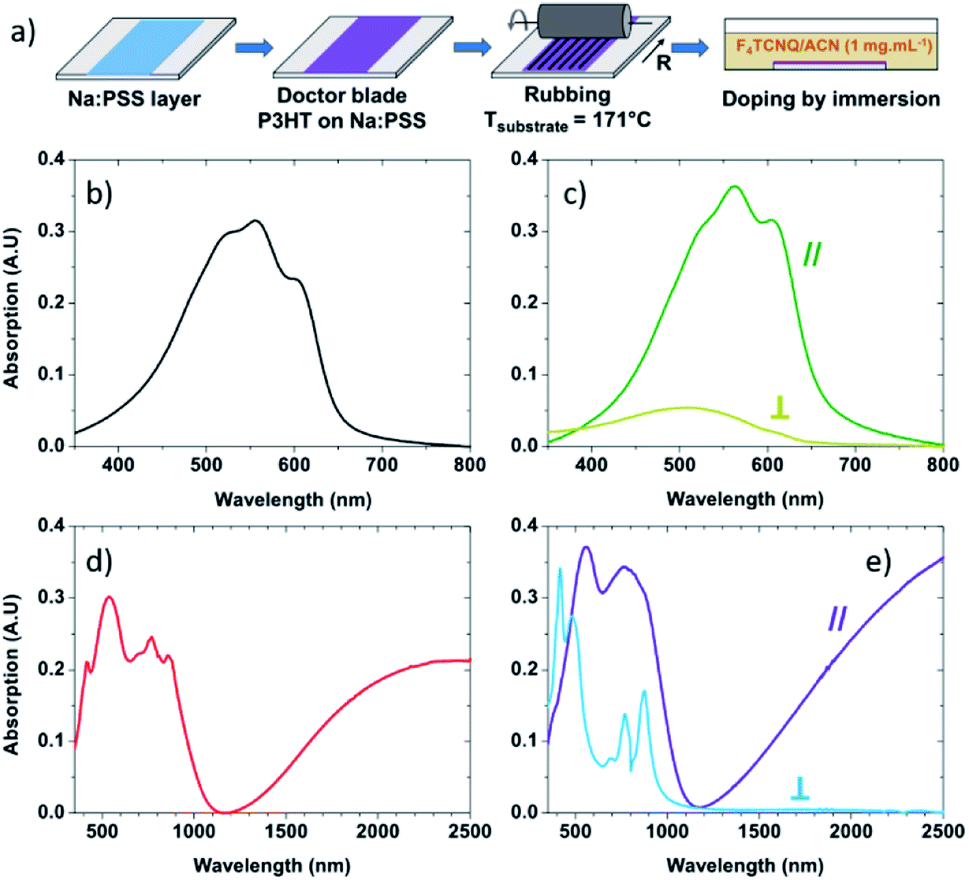 | ||
| Fig. 1 (a) Fabrication process of the highly-aligned and conductive films. UV-Vis absorbance spectra of (b) doctor bladed non-rubbed P3HT, (c) rubbed P3HT with the incident light polarization oriented along (∥, dark green) or perpendicular (⊥, light green) to the rubbing direction, (d) non-rubbed P3HT doped with F4TCNQ and (e) rubbed P3HT doped with F4TCNQ with the light polarization oriented along (∥, purple) or perpendicular (⊥, light blue) the rubbing direction. | ||
Electrical conductivity and Seebeck coefficient measurement
The details of the measurements and the average and maximum values of charge conductivity and Seebeck coefficient are described in detail in our previous works.46,54 All devices were fabricated on glass substrates, cleaned by ultrasonication in acetone, ethanol, Hellmanex and deionized water (3 times). The cleaned substrates were dried under nitrogen and exposed to plasma prior to film deposition. Gold electrical contacts (1 mm spacing between electrodes, 5 mm length) in a four-point probe geometry were deposited via controlled thermal evaporation through a shadow mask, at an average rate of 4–6 Å s−1 (40 nm thick). An initial layer of chromium (2.5 nm thick) was deposited prior the gold to promote a good adhesion on the glass substrates (evaporation rate 0.5–1 Å s−1). Oriented films of P3HT (deposited on top of the sacrificial Na:PSS layer) were floated on water and carefully recovered on the device with pre-deposited gold electrodes. They were subsequently doped by dipping into a F4TCNQ solution (1 mg mL−1 in acetonitrile) for a period of 30 seconds. The geometry of deposited gold electrodes allows determination of the charge transport and thermopower on the same substrate in directions both parallel and perpendicular to rubbing.Thermal conductivity measurement
Various methods are available to investigate the thermal conductivity of organic materials, each with advantages as well as limitations.53 The in-plane thermal conductivity was measured with a Linseis Thin Film Analyzer (TFA) by the 3ω-technique coupled to the Völklien geometry.55,56 The active measurement area of our pre-patterned test-chips consists of a free standing membrane of silicon nitride with a lithographically-defined metal wire running down its centre. This metal wire acts as a thin-film resistive heater and thermometer. The heat flux is from the centre of the membrane towards the edge making this an in-plane measurement of thermal conductivity in the direction perpendicular to the thin-film heater. The polymer films were vertically immersed in de-ionised water to dissolve the Na:PSS layer. The resulting free-standing (floating) films were transferred to TFA measurement chips with the rubbing direction either parallel or perpendicular to the heat flux of the measurement, thus enabling measurement of thermal conductivity parallel or perpendicular to the rubbing direction (Fig. S1†). Each reported thermal conductivity value represents the average value and standard deviation of three to four samples. Each sample was measured over a temperature range 293–373 K in vacuum (10−6 to 10−7 mbar), and several temperature sweeps were recorded in each case to check the stability of the measurement. The frequency of the heater current used was 0.8 Hz, and there as a stabilization time of 7 minutes per temperature step.Film thickness
The film thickness for each sample was averaged over ten locations around the freestanding membrane using a Dektak surface profilometer. Thickness measurements on any one sample typically deviated by ±∼10%. The average thickness of all our films in this study was 56 nm with a standard deviation of 19 nm. We did not observe a dependence of the thermal conductivity with film thickness.Misalignment of the film
We performed a 2D Fast Fourier Transform (2D-FFT) on optical microscope images of the high-temperature rubbed to obtain the misalignment of the ridges in regard of the heater line. Each sample was imaged on three different positions on the membranes and the angle between the rubbed P3HT and the heater was recorded. The average misalignment of each sample is obtained by averaging the three angles per image. The value of 2.8° cited in the text corresponds to the average value of all the images recorded (Fig. S2†).Atomic force microscopy
The topography and modulus images of the samples we obtained with a Bruker Dimension Icon atomic force microscope (AFM) with TAP525 (Bruker) tips (Mechanical Property mode, Quantitative Nanoscale Mechanical Characterization (QNM)). A typical PSFILM-12M sample (Bruker) was used as a reference with a known modulus of 2.7 GPa. After calibration, we used the tip to measure the Young modulus of our polymer films in Peak Force mode. We repeated this calibration process every between each sample to ensure the accuracy of the measured modulus. The Young's modulus fitting is reported in Fig. S6.†Raman spectroscopy
Raman spectra were recorded using a Renishaw InVia in back scattering configuration. The spectra were made recorded for 10 seconds using a ×100 objective lens under an excitation wavelength of 785 nm. The laser intensity was minimised to avoid photo-degradation of the samples.Results and discussion
Effect of chain alignment
The absorbance of neat non-rubbed P3HT (Fig. 1b) reveals widely reported absorption characteristics of the polymer: the 0–1 transition peak at 552 nm and the 0–0 transition peak at 601 nm.57–61 After rubbing at 171 °C, the absorbance of P3HT becomes highly polarized with strong absorbance of light polarized in the direction parallel to rubbing and significantly quenched absorption of light polarized in the direction perpendicular to rubbing (Fig. 1c). This suggests that the long axis of the polymer is oriented predominantly along the rubbing direction,44,46 something which can be quantified using the dichroic ratio (DR), defined as the ratio of the absorbance in directions parallel and perpendicular to rubbing.62,63 At the 0–0 transition peak (601 nm), the dichroic ratio of P3HT rubbed at 171 °C is 14.1, confirming a strong alignment of the conjugation along the rubbing direction. It is also possible to calculate a 3D order parameter, S = (DR − 1)/(DR + 2), which is commonly used to estimate the alignment of dye molecules in liquid crystals.64–66 A value of S = 1 indicates perfect alignment of molecular transition dipoles, whereas S = 0 is indicative of an isotropic film. In our case, S = 0.81, indicating excellent chain alignment in good agreement with our previous work.44When the non-rubbed films are doped with F4TCNQ (Fig. 1d), we note a quenching and broadening of the neutral region of the polymer (peak at ∼500 nm) compared to the neutral non-rubbed films, and the appearance of three sharp peaks (at 417 nm, ∼770 nm and 858 nm) all corresponding to the anionic form of the dopant. We also observe the emergence of two polaron bands, one at 650–1100 nm and a wide band above 1200 nm.60,61
After doping, the rubbed films (Fig. 1e) exhibit characteristic features of doped P3HT when the incident light is parallel to the rubbing direction. This includes neutral, and polaronic features of the P3HT chains. Peaks associated with neutral or charged F4TCNQ are barely visible. On the other hand, when the incident light is perpendicular to the rubbing direction, peaks corresponding to anionic F4TCNQ are clearly observed, whilst the broad P3HT polaronic bands are absent.60,61 This indicates that the alignment of P3HT chains is translated to the dopants, which sit within the alkyl side chains of the polymer with their transition dipoles perpendicular to the P3HT backbone.
The electron diffraction pattern of as-cast P3HT (Fig. 2a) presents a single Scherrer ring corresponding to the (0 2 0) reflection, typical of edge-on orientation of the crystalline domains and implies no specific orientation of the crystalline regions.43,67 Note that we previously estimated the crystallinity of P3HT films doctor-blade coated at 171 °C as 50%.44 Hence, the morphology of non-rubbed non doped P3HT consists of crystalline domains of various length scales randomly embedded in an amorphous phase. The thermal conductivities of the non-rubbed samples at room temperature parallel (κ∥) and perpendicular (κ⊥) to the deposition direction are 0.29 ± 0.09 W m−1 K−1 and 0.30 ± 0.08 W m−1 K−1, respectively (Fig. 2c). This is in the range expected for P3HT.68,69 The lack of anisotropy in thermal conductivity of the non-rubbed films, over the entire temperature range (Fig. S3†), suggests no or little preferential alignment of P3HT during the deposition. The thermal conductivity exhibits no significant temperature dependence, as observed for polymers above their glass transition temperature.70,71 For amorphous P3HT, the glass transition is expected to occur slightly below room temperature.72,73
 | ||
| Fig. 2 Electron diffraction patterns of non-rubbed (a) and rubbed P3HT films (b) before doping. The arrow, R, indicates the rubbing direction. Schematic of the crystal structure of P3HT (c) and (d) thermal conductivity of non-rubbed P3HT and P3HT rubbed at 171 °C, respectively. | ||
After rubbing at 171 °C, P3HT films present different diffraction patterns (Fig. 2b). The appearance of a 0 0 2 reflection that represents the intrachain periodicity between successive thiophene units, along the rubbing direction confirms that high-temperature rubbing effectively aligns our P3HT chains. The appearance of the equatorial reflections (h 0 0) (h = 1–3) represents a change of the contact plane of the crystalline domains from edge-on to face-on. Note that the persistence of a weakened 0 2 0 reflection shows that a small fraction of edge-on crystals is also present in the high-temperature rubbed films. Furthermore, a crystal structure emerges with polymer backbones separated by alkyl side chains (a-axis) at a distance of 16.6 Å, a π–π stacking distance of 3.8 Å (b-axis) and an intrachain distance between thiophene units of 3.85 Å (Fig. 2b). In our previous work, we demonstrated that the rubbing temperature controls the lamellar morphology and the crystallinity of the films.44 When P3HT is rubbed at temperatures higher than 144 °C, it crystallizes along the rubbing direction in a folded chain lamella fashion, forming a regular lamellar semi-crystalline morphology at a larger scale.44,46 Using a fast Fourier transform of bright-field transmission electronic microscope (BF-TEM) images, we reported the total lamellar period (alternating amorphous and crystalline phases) of the films rubbed at 171 °C is ∼17 nm.44 The degree of crystallinity of the 171 °C rubbed films was previously measured by differential scanning calorimetry (DSC) and found to be 33 ± 1.3%.44 Using the total length of the lamellar period and the crystallinity of the rubbed films, it can be estimated that the amorphous phase in the lamellar structure is about 11 nm long and the crystalline phase 6 nm long (Fig. S4†).
After rubbing, the thermal conductivity (Fig. 2d) along the rubbing direction is κ∥ = 0.59 ± 0.05 W m−1 K−1 at room temperature, double that of non-rubbed films, and remarkably high for a polymer. However, perpendicular to the rubbing direction, κ⊥ = 0.19 ± 0.08 W m−1 K−1 at room temperature, slightly lower than the isotropic films. The anisotropy coefficient, K = κ∥/κ⊥, of the thermal conductivity is K ≈ 3.1 over the entire temperature range (Fig. S3†). An anisotropic thermal conductivity has been previously observed for orientated polymers, with high thermal conductivity along the chain alignment direction, as in our case.71,74–77 We note that the lower thermal conductivity perpendicular to the chain alignment in our films may originate either in an intrinsically low thermal conductivity along the crystal a-axis which includes transport through the flexible alkyl side chains (non-interdigitated with only weak intermolecular van der Waals forces),71,78,79 or from a specific morphology of the films. Atomic force microscopy (Fig. S5†) reveals that high-temperature rubbing introduces a film morphology consisting of ridges running parallel to the rubbing direction. Therefore, in the direction perpendicular to rubbing, thermal transport can be reduced by bottlenecks in the morphology (thin regions of the film in the form of trenches between the ridges). On the other hand, the thermal conductivity measured along the rubbing direction is not subject to these bottlenecks in thermal transport and therefore represents the intrinsic thermal conductivity of the material.
We performed quantitative nanoscale mechanical characterization (QNM) to probe the effect of high-temperature rubbing on the polymer's mechanical properties. The elastic modulus of neat P3HT films, EP3HT, follows a sharp normal distribution, with EP3HT = 1.42 ± 0.16 GPa (Fig. S6†), in agreement with modulus values in the literature.80,81 After high temperature rubbing, the Young's modulus follows a multimodal distribution that reflects the trenches and ridges of the films (Fig. S6†). We performed a Gaussian fit to distinguish the Young's modulus of the two regions of the film (Fig. S6†). The broad peak centred at 3.15 GPa is associated with the trenches of the film morphology where the film is thinner. In this case, we expect the higher modulus to be due to the measurement feeling the effect of the substrate due to the confined geometry rather than an intrinsically high modulus state of the polymer. On the other hand, the ridges of the rubbed films exhibit a Young's modulus requiring at least two Gaussian peaks at 1.31 GPa and 1.86 GPa. As-deposited isotropic P3HT has an edge-on orientation, which implies that the mechanical characterization preferentially probes the flexible alkyl side chains (a-axis), whilst rubbed P3HT adopts a preferential face-on orientation, allowing mechanical probing of the π-stacking direction (b-axis). Therefore, the peak at 1.86 GPa in the rubbed films is most likely related to face-on P3HT regions with the smaller peak at 1.31 GPa likely due to residual edge-on regions.
The lattice thermal conductivity is proportional to the square root of the bulk modulus, E, as described by eqn (1) and (2).
| κ = (1/3)Cvsoundl | (1) |
 | (2) |
Effect of doping
At room temperature, the measured thermal conductivities of our isotropic (not rubbed), doped films are κ∥ = 1.08 ± 0.01 W m−1 K−1 and κ⊥ = 0.95 ± 0.01 W m−1 K−1, essentially isotropic (Fig. 3a and S3†). However, thermal conductivities of ∼1 W m−1 K−1 are surprising high for a semi-crystalline polymer without a specific orientation of the crystalline domains. Previous works on the thermal conductivity of conjugated polymers also revealed an improved thermal transport after doping. Among them, polyacetylene doped by AsF6, PEDOT:PSS and PEDOT:tosylate exhibit thermal conductivities of 0.7 W m−1 K−1, 0.84 to 1 W m−1 K−1 and 1.5 W m−1 K−1, respectively.15,82–84 In these cases, the increase in thermal conductivity was mostly ascribed to the electronic component of thermal conductivity, κel, given by: κel = σLT, where L is the Lorenz number and T is the temperature. What is most surprising for the non-rubbed films is the significant increase of κ despite a modest electrical conductivity of 8.9 ± 1.8 S cm−1 (Table 1). It should be noted that there is significant disagreement on the value of the Lorenz number in organic materials, with some putting the value up to 2.5 times the Sommerfeld value,15,84 and others measuring values equal to83 the Sommerfeld value. In our case, we expect an electronic contribution to the thermal conductivity at T = 300 K of just 0.007 ± 0.002 W m−1 K−1, assuming the Sommerfeld value of the Lorenz number, L. Even with a value of the Lorenz number that exceeds the Sommerfeld value by factor of 2.5,84 we would only expect an electronic contribution of κel < 0.02 W m−1 K−1. This leads us to believe that the remarkable increase in thermal conductivity upon doping cannot be attributed to an electronic contribution but originates from a modification to the lattice thermal conductivity, κlattice. | ||
| Fig. 3 Thermal conductivity of (a) non-rubbed doped P3HT and (b) rubbed doped P3HT. Electron diffraction pattern of (c) non-rubbed doped P3HT and (d) rubbed doped P3HT with a schematic of its crystal structure. The arrow, R, denotes the rubbing direction. The asterisk seen in (d) indicates reflections from PTFE used for calibration. | ||
| Average values | NR-D | R-D ∥ | R-D ⊥ |
|---|---|---|---|
| Electrical cond. (σ, S cm−1) | 8.9 ± 1.8 | 110 ± 10 | 11 ± 4 |
| Seebeck coeff. (S, μV K−1) | 55 ± 2 | 62 ± 4 | 14 ± 2 |
| Thermal cond. (κ, W m−1 K−1) | 1.08 ± 0.01 | 0.69 ± 0.04 | 0.14 ± 0.05 |
| Power factor (PF, μW m−1 K−2) | 2.7 ± 0.8 | 42 ± 9 | 0.22 ± 0.12 |
| Figure of merit (ZT) × 10−4 | 7.30 ± 2 | 180 ± 28 | 4.5 ± 1.1 |
We therefore studied molecular packing in these films too, finding that the ED pattern of the non-rubbed doped film (Fig. 3c) is slightly different from the non-doped analogue film (Fig. 2a). The Scherrer ring corresponding to the 0 2 0 reflection is still present, which suggests an edge-on orientation of the crystallite domains.54 However, the process of doping induces a sizable decrease of the average π–π stacking distance from 3.8 Å to 3.60 + 0.05 Å.
After sequential doping of the isotropic films, the topography and modulus images from QNM were recorded (Fig. S5†), and analysis shows an increase in the Young's modulus to 3.42 ± 0.39 GPa (Fig. S6†). This modulus is ∼2.5 times the modulus of the undoped analogue. It is known that the presence of polarons on conjugated polymer chains can increase their quinoidal character,85–88 with quinoidal chains being more rigid and more planar, and this might be the cause of the increase in the Young's modulus upon doping our films. Some previous work on P3HT:F4TCNQ indicated that the chains can straighten upon doping and their conjugation length increases, resulting in a better connectivity in the films.89 An analogous effect was reported by Kim et al. where the inclusion of short and rigid poly(N-acryloyl piperidine) (PAP) inside the gyration radius of poly(acrylic-acid) (PAA) flatten the PAA chains due to strong H-bonding.90 This resulted in an improved intrachain thermal transport, leading to an amorphous blend with a cross-plane thermal conductivity of 1.5 W m−1 K−1. Most of the doping in our films occurs in the crystalline regions by intercalation into the side chains, which may affect the thermal conductivity in the lamellar-stacking (a-axis) direction. However, the a-axis points out-of-plane in the non-rubbed films and is therefore not probed by the in-plane thermal conductivity measurements. Nonetheless, doping also decreases the π-stacking distance in these films. The edge-on morphology of the non-rubbed films makes the in-plane thermal conductivity measurement sensitive to this reduction in π-stacking distance, which would most likely be an extra factor increasing the thermal conductivity.
The rubbed doped films exhibit, at room temperature, a thermal conductivity of κ∥ = 0.69 ± 0.04 W m−1 K−1 and κ⊥ = 0.14 ± 0.05 W m−1 K−1 (Fig. 3b). Doping of highly-oriented rubbed films therefore only induces a small increase of the thermal conductivity along the rubbing direction compared to the rubbed but not doped analogue (for which κ∥ = 0.59 ± 0.05 W m−1 K−1). Considering the electrical conductivity of these films parallel to the rubbing direction, σ∥ = 110 ± 10 S cm−1 (Table 1), and the Sommerfeld value of the Lorenz number, the electronic contribution to the thermal conductivity at room temperature is expected to be, κel,∥ = 0.079 ± 0.007 W m−1 K−1, which adequately describes the modest increase of thermal conductivity in this direction after doping.
The electron diffraction pattern of the rubbed-doped films (Fig. 3d) presents similar reflections to the rubbed non-doped films. However, we note an increase in the intensity of the 0 0 2 and a streaking of this reflection while the 1 0 2 and 2 0 2 reflections tend to disappear. This indicates that dopant intercalation induces a re-organization of P3HT backbones within individual π-stacks and a disordering of alkyl side chains.54 Furthermore, the intercalation of F4TCNQ in the crystalline domains modifies the intermolecular unit cell parameters. The interlamellar distance (a-axis) increases to 18.1 Å while the π–π distance (b-axis) decreases to 3.60 ± 0.05 Å. A schematic of the structure of the crystalline regions of the rubbed doped films is shown in Fig. 3d. We note that the face-on orientation of the rubbed films would mean that the increase in lamellar stacking distance upon doping (along with the disordering of the sidechains) is probed by the in-plane thermal conductivity measurements, which would most likely limit the measured thermal conductivity due to weaker intermolecular coupling and increased scattering in this direction.
After sequential doping of the rubbed films, there remains a multimodal distribution of the Young's modulus (Fig. S6†). We used a similar fit as for the rubbed non-doped samples to observe the effect of doping on the stiffness of the films. The Young modulus distribution is best fitted with two peaks, one centred at 2.23 GPa and another at 3.29 GPa. Notably, the soft component at 1.31 GPa in the rubbed but not doped films, that we believe probes the residual edge-on material, is no longer present, being incorporated into the peak at 2.23 GPa after doping. This adds weight to the argument that stiffening of the a-axis of crystalline regions is induced by doping. This result confirms that sequential doping does induce a more rigid polymer film in the lamellar packing direction.
We further looked at the effect of high-temperature rubbing and doping on the molecular packing using Raman spectroscopy. We used an excitation wavelength of 785 nm as it is resonant with the doped segments in the films. The assignment of the thiophene stretching modes on P3HT was made according to existing literature.91–96 Furthermore, the laser polarization allowed us to qualitatively probe the impact of rubbing and doping parallel and perpendicular to the deposition direction. The complete Raman analysis and the deconvolution methodology for of pristine and doped films can be found in the ESI.† Here, we focus our attention on the intra-ring C–C and C![[double bond, length as m-dash]](https://www.rsc.org/images/entities/char_e001.gif) C stretching modes (1300–1600 cm−1). In what follows, “order” refers to intrachain order, and not necessarily interchain crystallinity, which allows us to detect increases in order in crystalline and amorphous regions alike. An “ordered” mode would relate to a polymer segment where there is a long conjugation length containing a large number of thiophene units and high degree of planarity. Conversely a “disordered” mode would be of short conjugation length and/or low degree of planarity.97 When polarons are considered, we split the definitions of ordered and disordered chain segments into neutral and charged. Neutral ordered and neutral disordered chain segments are as defined described above. Charged ordered and charged disordered chain segments are polaron-containing chain segments that were ordered and disordered, respectively, in their neutral state.91 The polaron will planarise the polymer locally in each case, but the difference in polaron structure between “ordered” and “disordered” cases comes from the effective conjugation length which is larger on the initially “ordered” segments. On these ordered segments there is a relatively small conformational change to accommodate the polaron, but there are larger changes in bond length when a polaron forms on shorter segments causing greater shifts in the Raman signal.91 It is therefore possible to distinguish polarons on ordered (long conjugation length) and disordered (short conjugation length) chain segments.
C stretching modes (1300–1600 cm−1). In what follows, “order” refers to intrachain order, and not necessarily interchain crystallinity, which allows us to detect increases in order in crystalline and amorphous regions alike. An “ordered” mode would relate to a polymer segment where there is a long conjugation length containing a large number of thiophene units and high degree of planarity. Conversely a “disordered” mode would be of short conjugation length and/or low degree of planarity.97 When polarons are considered, we split the definitions of ordered and disordered chain segments into neutral and charged. Neutral ordered and neutral disordered chain segments are as defined described above. Charged ordered and charged disordered chain segments are polaron-containing chain segments that were ordered and disordered, respectively, in their neutral state.91 The polaron will planarise the polymer locally in each case, but the difference in polaron structure between “ordered” and “disordered” cases comes from the effective conjugation length which is larger on the initially “ordered” segments. On these ordered segments there is a relatively small conformational change to accommodate the polaron, but there are larger changes in bond length when a polaron forms on shorter segments causing greater shifts in the Raman signal.91 It is therefore possible to distinguish polarons on ordered (long conjugation length) and disordered (short conjugation length) chain segments.
Prior to doping, the Raman spectra of the non-doped isotropic and rubbed P3HT films are comparable parallel and perpendicular to the deposition/rubbing direction (Fig. S8–S10†). Upon doping with F4TCNQ, differences arise. Along the doctor blade direction, non-rubbed doped P3HT (NR-D ∥, Fig. 4a and b) shows a broadening of the CC intraring modes, namely CC charged disordered (1405 cm−1) and CC charged ordered (∼1420 cm−1). It can be seen from the deconvolution that the resulting CC intraring mode after doping contains significant CC charged ordered components and only a small CC charged disordered contribution (Fig. 4a and b). This indicates that ordered chain segments are doped preferentially to disordered ones in this process. Nonetheless, the isotropic doped films remain mainly in a neutral state (Fig. 4a and b). This picture is similar for spectra taken perpendicular to the deposition direction (NR-D ⊥) and for the rubbed films perpendicular to the rubbing direction (R-D ⊥).
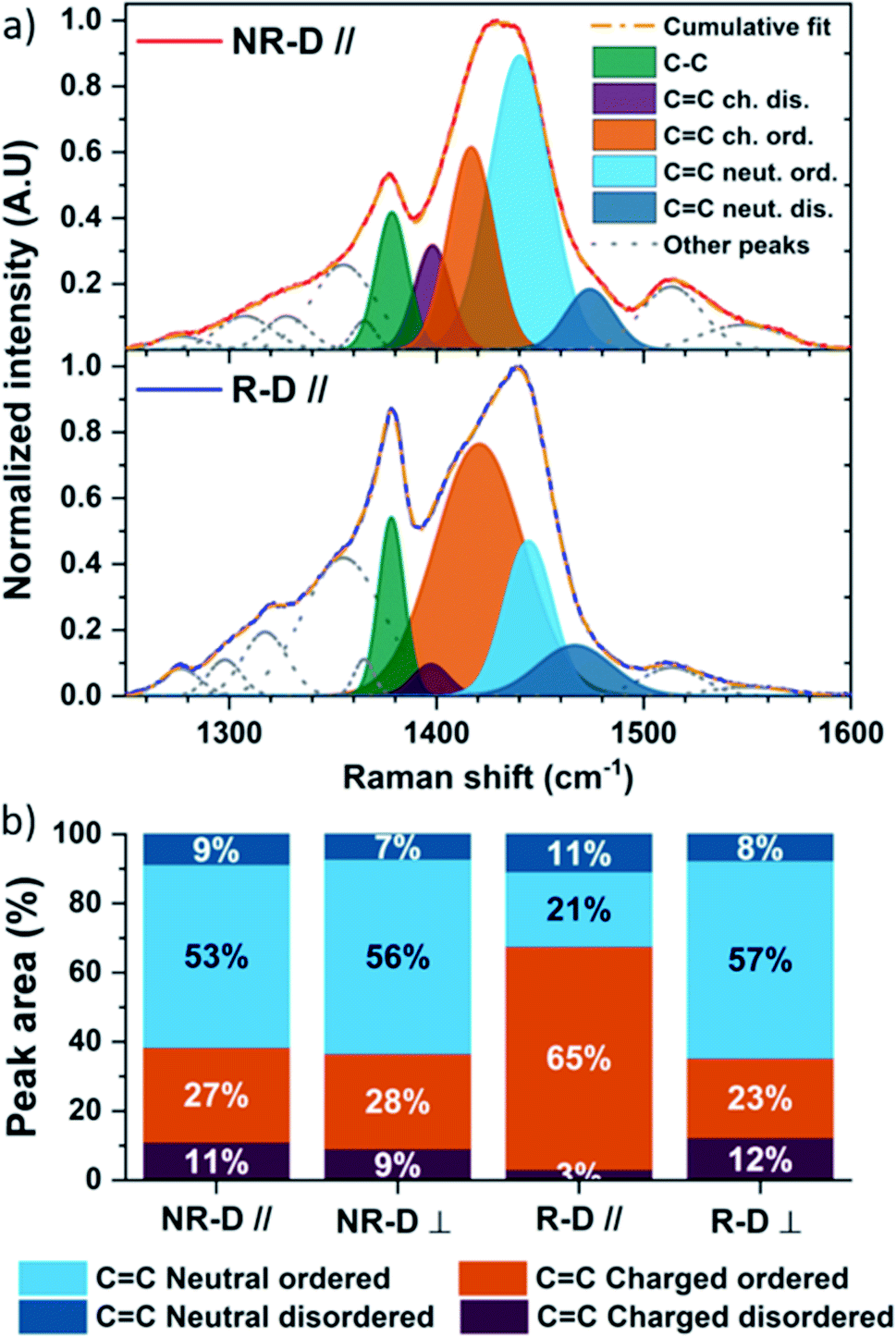 | ||
| Fig. 4 Raman spectroscopy under 785 nm excitation of the principal molecular vibrations on the thiophene ring: C–C stretching, CC charged (dis)ordered, CC neutral (dis)ordered, (a) isotropic doped (NR-D) and rubbed doped (R-D) P3HT along the deposition direction, and (b) total integrated peak area of the four vibration modes of CC ring breathing for isotropic doped and rubbed doped P3HT in both directions. | ||
On the other hand, Raman spectra of doped rubbed films parallel to the rubbing direction are radically different (R-D ∥, Fig. 4a and b). Firstly, the proportion of CC charged disordered stretching is only 3%. Secondly, doping induces a large increase of the CC charged ordered stretching centred at 1421 cm−1, making it the main contribution to the total integrated peak area at 65% (Fig. 4a and b). This indicates a higher degree of doping for chains aligned with the rubbing direction compared to all other cases, but also that the polarons lie on chain segments with longer average conjugation and/or lower torsion angles, which will result in greater charge delocalisation.
The ratio of the C–C intraring mode to the combined CC intraring modes (IC–C/ICC) is known to increase with molecular order of the chain segments due to greater electron density over the intraring C–C bond in planar, ordered P3HT.97IC–C/ICC for the rubbed films parallel to the rubbing direction (R-D ∥, Fig. 4a) is larger than all other doped cases (Fig. S11†). Such enhancement is probably due to a transition from aromatic to quinoid upon doping, leading to enhanced planarity, which is eased by the specific morphology after rubbing.
Critically, not only does morphology influence the degree of doping, we have found that doping has a strong effect on the morphology. Doping is known to flatten the polymer chains and reduce the dihedral angle between adjacent P3HT monomers thereby increasing the conjugation length and chain stiffness.91 This is supported by the redshift to 1440 cm−1 of the CC neutral ordered vibration mode of isotropic doped films, which indicates a longer conjugation length of the polymer chains.97 As a result, this new morphology adopted after doping is different than that of the neat polymer, and may explain why the Young modulus and thermal conductivity increase despite the moderate increase in electrical conductivity. In contrast, the rubbed morphology along the rubbing direction promotes loading of F4TCNQ into the film and seems to limit the impact of doping on the remaining neutral chains. It transpires that the doped phase with highest thermal conductivity is not observed along the rubbing direction despite the high electrical conductivity of the films, and this is highly beneficial for ZT.
Power factor and ZT
The isotropic doped films exhibit an electrical conductivity of 8.9 ± 1.8 S cm−1 (Table 1), similar to the values recently reported for P3HT:F4TCNQ thin films.29 The Seebeck coefficient reaches 55 ± 2 μV K−1, and the power factor (PF) is therefore 2.7 ± 0.8 μW m−1 K−1.High-temperature rubbing introduces a strong anisotropy to the electrical conductivity, with the electrical conductivity increasing to 110 S cm−1 along the rubbing direction, an order of magnitude higher than in the non-rubbed doped films.54 We previously observed an anisotropy in hole mobility of almost an order of magnitude in rubbed P3HT (rubbed at ∼171 °C) and it seems that this is translated directly into an anisotropic electrical conductivity (σ∥/σ⊥ = 10 ± 4).44,46 The high electrical conductivity along the rubbing direction compared to the perpendicular direction and the non-rubbed films is consistent with the Raman analysis which shows a greater proportion of doped polymer chains aligned with the rubbing direction, along with a greater proportion of polarons on ordered chain segments showing a larger planarity.
Astonishingly, despite the large increase in σ in the rubbing direction, S∥ (=62 ± 4 μV K−1) is significantly higher than in the perpendicular direction (S⊥ = 14 ± 2 μV K−1) and slightly higher than in the doped non-rubbed films (SNR = 55 ± 2 μV K−1). This confirms that the decoupling of S and σ is a consequence of high-temperature rubbing, as reported by Hamidi-Sakr et al. and Untilova et al.46,54 Consequently, PF∥ = 42 ± 6 μV K−1 is among the highest reported for P3HT:F4TCNQ thin films. In the direction perpendicular to rubbing, PF⊥ = 0.2 ± 0.1 μV K−1, leading to a power factor anisotropy of PF∥/PF⊥ = 210.
Due to the surprisingly high thermal conductivity of 1.08 ± 0.01 W m−1 K−1, the isotropic doped films have a low figure of merit, ZT = 7.3 ± 2 × 10⁻⁴. Note that this is comparable to the ZT measured perpendicular to the rubbing direction despite a PF ten times higher for the isotropic doped films (Table 1). On the other hand, despite a large increase of κ∥ after rubbing and doping P3HT, ZT∥ = 1.79 ± 0.28 × 10⁻². This value represents an improved ZT by a factor 25 compared to the isotropic films and highlights the importance of using morphological control in the development of high ZT polymer thermoelectrics.
Conclusions
This work has shown that the thermal conductivity of thermoelectric polymer films is highly tuneable by a factor of at least 5 from <0.2 W m−1 K−1 to >1 W m−1 K−1. This challenges the assumption that polymer thermoelectric materials always benefit from lower thermal conductivities than their ceramic counterparts. The polycrystalline structure of rubbed films was shown to induce an anisotropic thermal conductivity with high κ along the polymer chains. Doping of rubbed films was shown not to have a significant additional effect on the thermal conductivity other than a small increase that was consistent with an electronic contribution. On the other hand, doping of polymer films in the absence of rubbing induced significant changes to the molecular packing and morphology, yielding exceptionally high lattice thermal conductivity, above 1 W m−1 K−1 which is unusual for a polymer and detrimental to the thermoelectric figure of merit, ZT. Nanomechanical analysis revealed that a stiffer phase developed upon doping, which suggests that the high thermal conductivity originates from a modified morphology likely to be due to the stiffening or straightening of polymer chains in the amorphous regions. This drastic increase in κ reinforces the point that an improved power factor does not necessarily translate to an improvement in ZT. Nonetheless, despite the discovery of high thermal conductivity states, mechanical rubbing results in a power factor enhancement along the rubbing direction that far outweighs the increase in thermal conductivity, resulting in a 25-fold improvement in ZT as compared to the isotropic doped films.This work has highlighted that morphological control is key in the development of polymer thermoelectrics and that it should not be assumed that the lattice thermal conductivity is constant as a function of processing or doping. Such assumptions may lead to miscalculation of the figure of merit.
Conflicts of interest
There are no conflicts to declare.Acknowledgements
This work was supported by O. F.'s Royal Society University Research Fellowship (UF140372 & UF URF/R/201013). M. B. acknowledges financial support from ANR contract ANR-17-CE05-0012 and PEPS Thermobody. V. U. thanks Region Grand'Est for PhD grant and V. V. acknowledges support form Strasbourg University for a PhD Attractivity Grant. The TEM platform of ICS is thanked for technical support. X. Xu is funded by the Chinese Scholarship Council.Notes and references
- F. S. Kim, G. Ren and S. A. Jenekhe, Chem. Mater., 2011, 23, 682–732 CrossRef CAS.
- S. Allard, M. Forster, B. Souharce, H. Thiem and U. Scherf, Angew. Chem., Int. Ed., 2008, 47, 4070–4098 CrossRef CAS.
- Y. Liu, J. Zhao, Z. Li, C. Mu, W. Ma, H. Hu, K. Jiang, H. Lin, H. Ade and H. Yan, Nat. Commun., 2014, 5, 5293 CrossRef CAS PubMed.
- P. A. Lane, L. C. Palilis, D. F. O'Brien, C. Giebeler, A. J. Cadby, D. G. Lidzey, A. J. Campbell, W. Blau and D. D. C. Bradley, Phys. Rev. B: Condens. Matter Mater. Phys., 2001, 63, 235206 CrossRef.
- V. Vohra, F. Galeotti, U. Giovanella, W. Mróz, M. Pasini and C. Botta, ACS Appl. Mater. Interfaces, 2018, 10, 11794–11800 CrossRef CAS PubMed.
- M. S. Vezie, S. Few, I. Meager, G. Pieridou, B. Dörling, R. S. Ashraf, A. R. Goñi, H. Bronstein, I. McCulloch, S. C. Hayes, M. Campoy-Quiles and J. Nelson, Nat. Mater., 2016, 15, 746 CrossRef CAS PubMed.
- Y. Guo, D. Shi, Z.-W. Luo, J.-R. Xu, M.-L. Li, L.-H. Yang, Z.-Q. Yu, E.-Q. Chen and H.-L. Xie, Macromolecules, 2017, 50, 9607–9616 CrossRef CAS.
- H. Chen, M. Hurhangee, M. Nikolka, W. Zhang, M. Kirkus, M. Neophytou, S. J. Cryer, D. Harkin, P. Hayoz, M. Abdi-Jalebi, C. R. McNeill, H. Sirringhaus and I. McCulloch, Adv. Mater., 2017, 29, 1702523 CrossRef PubMed.
- M. Nikolka, K. Broch, J. Armitage, D. Hanifi, P. J. Nowack, D. Venkateshvaran, A. Sadhanala, J. Saska, M. Mascal, S.-H. Jung, J. K. Lee, I. McCulloch, A. Salleo and H. Sirringhaus, Nat. Commun., 2019, 10, 2122 CrossRef PubMed.
- M. Jaiswal and R. Menon, Polym. Int., 2006, 55, 1371–1384 CrossRef CAS.
- L. M. Cowen, J. Atoyo, M. J. Carnie, D. Baran and B. C. Schroeder, ECS J. Solid State Sci. Technol., 2017, 6, N3080–N3088 CrossRef CAS.
- M. Bharti, A. Singh, S. Samanta and D. K. Aswal, Prog. Mater. Sci., 2018, 93, 270–310 CrossRef CAS.
- E. Bilotti, O. Fenwick, B. C. Schroeder, M. Baxendale, P. Taroni-Junior, T. Degousée and Z. Liu, in Comprehensive Composite Materials II, Elsevier, Oxford, 2018, pp. 408–430, DOI: DOI:10.1016/B978-0-12-803581-8.10024-4.
- B. Russ, A. Glaudell, J. J. Urban, M. L. Chabinyc and R. A. Segalman, Nat. Rev. Mater., 2016, 1, 16050 CrossRef CAS.
- D. Moses and A. Denenstein, Phys. Rev. B: Condens. Matter Mater. Phys., 1984, 30, 2090–2097 CrossRef CAS.
- G. H. Kim, L. Shao, K. Zhang and K. P. Pipe, Nat. Mater., 2013, 12, 719 CrossRef CAS.
- Y. Yang, in Physical Properties of Polymers Handbook, ed. J. E. Mark, Springer New York, New York, NY, 2007, pp. 155–163, DOI: DOI:10.1007/978-0-387-69002-5_10.
- D. M. Price and M. Jarratt, Thermochim. Acta, 2002, 392–393, 231–236 CrossRef CAS.
- Y. Sun, P. Sheng, C. Di, F. Jiao, W. Xu, D. Qiu and D. Zhu, Adv. Mater., 2012, 24, 932–937 CrossRef CAS PubMed.
- K. Kang, S. Schott, D. Venkateshvaran, K. Broch, G. Schweicher, D. Harkin, C. Jellett, C. B. Nielsen, I. McCulloch and H. Sirringhaus, Mater. Today Phys., 2019, 8, 112–122 CrossRef.
- H. Shi, C. Liu, Q. Jiang and J. Xu, Adv. Electron. Mater., 2015, 1, 1500017 CrossRef.
- Y. Sun, L. Qiu, L. Tang, H. Geng, H. Wang, F. Zhang, D. Huang, W. Xu, P. Yue, Y.-s. Guan, F. Jiao, Y. Sun, D. Tang, C.-a. Di, Y. Yi and D. Zhu, Adv. Mater., 2016, 28, 3351–3358 CrossRef CAS PubMed.
- V. Vijayakumar, Y. Zhong, V. Untilova, M. Bahri, L. Herrmann, L. Biniek, N. Leclerc and M. Brinkmann, Adv. Energy Mater., 2019, 9, 1900266 CrossRef.
- P. Pingel and D. Neher, Phys. Rev. B: Condens. Matter Mater. Phys., 2013, 87, 115209 CrossRef.
- H. Méndez, G. Heimel, S. Winkler, J. Frisch, A. Opitz, K. Sauer, B. Wegner, M. Oehzelt, C. Röthel, S. Duhm, D. Többens, N. Koch and I. Salzmann, Nat. Commun., 2015, 6, 8560 CrossRef PubMed.
- Z. Liang, Y. Zhang, M. Souri, X. Luo, A. M. Boehm, R. Li, Y. Zhang, T. Wang, D.-Y. Kim, J. Mei, S. R. Marder and K. R. Graham, J. Mater. Chem. A, 2018, 6, 16495–16505 RSC.
- D. T. Scholes, P. Y. Yee, G. R. McKeown, S. Li, H. Kang, J. R. Lindemuth, X. Xia, S. C. King, D. S. Seferos, S. H. Tolbert and B. J. Schwartz, Chem. Mater., 2019, 31, 73–82 CrossRef CAS.
- C. J. Boyle, M. Upadhyaya, P. Wang, L. A. Renna, M. Lu-Díaz, S. Pyo Jeong, N. Hight-Huf, L. Korugic-Karasz, M. D. Barnes, Z. Aksamija and D. Venkataraman, Nat. Commun., 2019, 10, 2827 CrossRef PubMed.
- D. T. Scholes, P. Y. Yee, J. R. Lindemuth, H. Kang, J. Onorato, R. Ghosh, C. K. Luscombe, F. C. Spano, S. H. Tolbert and B. J. Schwartz, Adv. Funct. Mater., 2017, 27, 1702654 CrossRef.
- R. Noriega, J. Rivnay, K. Vandewal, F. P. V. Koch, N. Stingelin, P. Smith, M. F. Toney and A. Salleo, Nat. Mater., 2013, 12, 1038 CrossRef CAS PubMed.
- A. B. Kaiser, G. U. Flanagan, D. M. Stewart and D. Beaglehole, Synth. Met., 2001, 117, 67–73 CrossRef CAS.
- S. D. Kang and G. J. Snyder, Nat. Mater., 2016, 16, 252 CrossRef PubMed.
- M. Qiu and M. Baxendale, Org. Electron., 2019, 105553, DOI:10.1016/j.orgel.2019.105553.
- M. Statz, D. Venkateshvaran, X. Jiao, S. Schott, C. R. McNeill, D. Emin, H. Sirringhaus and R. Di Pietro, Commun. Phys., 2018, 1, 16 CrossRef.
- H. Sirringhaus, P. J. Brown, R. H. Friend, M. M. Nielsen, K. Bechgaard, B. M. W. Langeveld-Voss, A. J. H. Spiering, R. A. J. Janssen, E. W. Meijer, P. Herwig and D. M. de Leeuw, Nature, 1999, 401, 685 CrossRef CAS.
- S. Fabiano, H. Yoshida, Z. Chen, A. Facchetti and M. A. Loi, ACS Appl. Mater. Interfaces, 2013, 5, 4417–4422 CrossRef CAS PubMed.
- M. Brinkmann and J. C. Wittmann, Adv. Mater., 2006, 18, 860–863 CrossRef CAS.
- M. Brinkmann, J. Polym. Sci., Part B: Polym. Phys., 2011, 49, 1218–1233 CrossRef CAS.
- L. Deng and G. Chen, Nano Energy, 2021, 80, 105448 CrossRef CAS.
- M. Brinkmann, L. Hartmann, L. Biniek, K. Tremel and N. Kayunkid, Macromol. Rapid Commun., 2013, 35, 9–26 CrossRef PubMed.
- D. Khim, A. Luzio, G. E. Bonacchini, G. Pace, M.-J. Lee, Y.-Y. Noh and M. Caironi, Adv. Mater., 2018, 30, 1705463 CrossRef.
- Y. Nogami, H. Kaneko, T. Ishiguro, A. Takahashi, J. Tsukamoto and N. Hosoito, Solid State Commun., 1990, 76, 583–586 CrossRef CAS.
- L. Biniek, N. Leclerc, T. Heiser, R. Bechara and M. Brinkmann, Macromolecules, 2013, 46, 4014–4023 CrossRef CAS.
- A. Hamidi-Sakr, L. Biniek, S. Fall and M. Brinkmann, Adv. Funct. Mater., 2015, 26, 408–420 CrossRef.
- J. Tsukamoto, A. Takahashi and K. Kawasaki, Jpn. J. Appl. Phys., 1990, 29, 125–130 CrossRef CAS.
- A. Hamidi-Sakr, L. Biniek, J. -L. Bantignies, D. Maurin, L. Herrmann, N. Leclerc, P. Lévêque, V. Vijayakumar, N. Zimmermann and M. Brinkmann, Adv. Funct. Mater., 2017, 27, 1700173 CrossRef.
- A. Henry, Annu. Rev. Heat Transfer, 2014, 17, 485–520 CrossRef.
- C. L. Choy, Polymer, 1977, 18, 984–1004 CrossRef CAS.
- H. Ma and Z. Tian, Appl. Phys. Lett., 2015, 107, 073111 CrossRef.
- S. Shen, A. Henry, J. Tong, R. Zheng and G. Chen, Nat. Nanotechnol., 2010, 5, 251 CrossRef CAS PubMed.
- Y. Xu, X. Wang, J. Zhou, B. Song, Z. Jiang, E. M. Y. Lee, S. Huberman, K. K. Gleason and G. Chen, Sci. Adv., 2018, 4, eaar3031 CrossRef.
- V. Singh, T. L. Bougher, A. Weathers, Y. Cai, K. Bi, M. T. Pettes, S. A. McMenamin, W. Lv, D. P. Resler, T. R. Gattuso, D. H. Altman, K. H. Sandhage, L. Shi, A. Henry and B. A. Cola, Nat. Nanotechnol., 2014, 9, 384 CrossRef CAS PubMed.
- H. Wang, W. Chu and G. Chen, Adv. Electron. Mater., 2019, 5, 1900167 CrossRef CAS.
- V. Untilova, T. Biskup, L. Biniek, V. Vijayakumar and M. Brinkmann, Macromolecules, 2020, 53, 2441–2453 CrossRef CAS.
- V. Linseis, F. Völklein, H. Reith, K. Nielsch and P. Woias, Rev. Sci. Instrum., 2018, 89, 015110 CrossRef CAS PubMed.
- V. Linseis, F. Völklein, H. Reith, P. Woias and K. Nielsch, J. Mater. Res., 2016, 31, 3196–3204 CrossRef CAS.
- P. J. Brown, D. S. Thomas, A. Köhler, J. S. Wilson, J.-S. Kim, C. M. Ramsdale, H. Sirringhaus and R. H. Friend, Phys. Rev. B: Condens. Matter Mater. Phys., 2003, 67, 064203 CrossRef.
- C. Hellmann, F. Paquin, N. D. Treat, A. Bruno, L. X. Reynolds, S. A. Haque, P. N. Stavrinou, C. Silva and N. Stingelin, Adv. Mater., 2013, 25, 4906–4911 CrossRef CAS PubMed.
- Y. Xuan, X. Liu, S. Desbief, P. Leclère, M. Fahlman, R. Lazzaroni, M. Berggren, J. Cornil, D. Emin and X. Crispin, Phys. Rev. B: Condens. Matter Mater. Phys., 2010, 82, 115454 CrossRef.
- D. T. Duong, C. Wang, E. Antono, M. F. Toney and A. Salleo, Org. Electron., 2013, 14, 1330–1336 CrossRef CAS.
- I. E. Jacobs, E. W. Aasen, J. L. Oliveira, T. N. Fonseca, J. D. Roehling, J. Li, G. Zhang, M. P. Augustine, M. Mascal and A. J. Moulé, J. Mater. Chem. C, 2016, 4, 3454–3466 RSC.
- A. Ghanadzadeh and M. S. Zakerhamidi, J. Mol. Liq., 2004, 109, 149–154 CrossRef CAS.
- A. Maleki, Z. Seidali, M. S. Zakerhamidi and M. H. M. Ara, Optik, 2015, 126, 5473–5477 CrossRef CAS.
- I. Haller and F. B. Kaufman, J. Am. Chem. Soc., 1976, 98, 1464–1468 CrossRef CAS.
- D. L. White and G. N. Taylor, J. Appl. Phys., 1974, 45, 4718–4723 CrossRef CAS.
- J. Küpfer and H. Finkelmann, Macromol. Rapid Commun., 1991, 12, 717–726 CrossRef.
- L. Hartmann, K. Tremel, S. Uttiya, E. Crossland, S. Ludwigs, N. Kayunkid, C. Vergnat and M. Brinkmann, Adv. Funct. Mater., 2011, 21, 4047–4057 CrossRef CAS.
- C. Bounioux, P. Díaz-Chao, M. Campoy-Quiles, M. S. Martín-González, A. R. Goñi, R. Yerushalmi-Rozen and C. Müller, Energy Environ. Sci., 2013, 6, 918–925 RSC.
- J. C. Duda, P. E. Hopkins, Y. Shen and M. C. Gupta, Appl. Phys. Lett., 2013, 102, 251912 CrossRef.
- W. N. dos Santos, J. A. de Sousa and R. Gregorio, Polym. Test., 2013, 32, 987–994 CrossRef CAS.
- C. L. Choy, F. C. Chen and W. H. Luk, J. Polym. Sci., Polym. Phys. Ed., 1980, 18, 1187–1207 CrossRef CAS.
- Y. Zhao, G. Yuan, P. Roche and M. Leclerc, Polymer, 1995, 36, 2211–2214 CrossRef CAS.
- N. Trinh Tung, N. Duc Nghia and N. Van Tuyen, Adv. Nat. Sci.: Nanosci. Nanotechnol., 2012, 3, 045001 Search PubMed.
- B. D. Washo and D. Hansen, J. Appl. Phys., 1969, 40, 2423–2427 CrossRef CAS.
- H. Ushirokita and H. Tada, Chem. Lett., 2016, 45, 735–737 CrossRef CAS.
- K. Kurabayashi, Int. J. Thermophys., 2001, 22, 277–288 CrossRef CAS.
- X. Feng, G. Liu, S. Xu, H. Lin and X. Wang, Polymer, 2013, 54, 1887–1895 CrossRef CAS.
- A. Henry, G. Chen, S. J. Plimpton and A. Thompson, Phys. Rev. B: Condens. Matter Mater. Phys., 2010, 82, 144308 CrossRef.
- W. Shi, Z. Shuai and D. Wang, Adv. Funct. Mater., 2017, 27, 1702847 CrossRef.
- S. Savagatrup, A. S. Makaram, D. J. Burke and D. J. Lipomi, Adv. Funct. Mater., 2014, 24, 1169–1181 CrossRef CAS.
- D. Tahk, H. H. Lee and D.-Y. Khang, Macromolecules, 2009, 42, 7079–7083 CrossRef CAS.
- Q. Wei, M. Mukaida, K. Kirihara and T. Ishida, ACS Macro Lett., 2014, 3, 948–952 CrossRef CAS.
- J. Liu, X. Wang, D. Li, N. E. Coates, R. A. Segalman and D. G. Cahill, Macromolecules, 2015, 48, 585–591 CrossRef CAS.
- A. Weathers, Z. U. Khan, R. Brooke, D. Evans, M. T. Pettes, J. W. Andreasen, X. Crispin and L. Shi, Adv. Mater., 2015, 27, 2101–2106 CrossRef CAS PubMed.
- J. L. Brédas, B. Thémans, J. G. Fripiat, J. M. André and R. R. Chance, Phys. Rev. B: Condens. Matter Mater. Phys., 1984, 29, 6761–6773 CrossRef.
- G. B. S. J. L. Bredas, Acc. Chem. Res., 1985, 18, 309–315 CrossRef.
- C. Enengl, S. Enengl, S. Pluczyk, M. Havlicek, M. Lapkowski, H. Neugebauer and E. Ehrenfreund, ChemPhysChem, 2016, 17, 3836–3844 CrossRef PubMed.
- J. Yamamoto and Y. Furukawa, J. Phys. Chem. B, 2015, 119, 4788–4794 CrossRef PubMed.
- A. R. Chew, R. Ghosh, Z. Shang, F. C. Spano and A. Salleo, J. Phys. Chem. Lett., 2017, 8, 4974–4980 CrossRef CAS PubMed.
- G.-H. Kim, D. Lee, A. Shanker, L. Shao, M. S. Kwon, D. Gidley, J. Kim and K. P. Pipe, Nat. Mater., 2014, 14, 295 CrossRef PubMed.
- J. Nightingale, J. Wade, D. Moia, J. Nelson and J.-S. Kim, J. Phys. Chem. C, 2018, 122, 29129–29140 CrossRef.
- G. Louarn, J. Y. Mévellec, S. Lefrant, J. P. Buisson, D. Fichou and M. P. Teulade-Fichou, Synth. Met., 1995, 69, 351–352 CrossRef.
- G. Louarn, M. Trznadel, J. P. Buisson, J. Laska, A. Pron, M. Lapkowski and S. Lefrant, J. Phys. Chem. A, 1996, 100, 12532–12539 CrossRef.
- S. Lefrant, I. Baltog, M. Lamy de la Chapelle, M. Baibarac, G. Louarn, C. Journet and P. Bernier, Synth. Met., 1999, 100, 13–27 CrossRef.
- B. Sainbileg, Y.-B. Lan, J.-K. Wang and M. Hayashi, J. Phys. Chem. C, 2018, 122, 4224–4231 CrossRef.
- T. J. Magnanelli and A. E. Bragg, J. Phys. Chem. Lett., 2015, 6, 438–445 CrossRef.
- W. C. Tsoi, D. T. James, J. S. Kim, P. G. Nicholson, C. E. Murphy, D. D. C. Bradley, J. Nelson and J.-S. Kim, J. Am. Chem. Soc., 2011, 133, 9834–9843 CrossRef PubMed.
Footnote |
| † Electronic supplementary information (ESI) available. See DOI: 10.1039/d1ta03377h |
| This journal is © The Royal Society of Chemistry 2021 |