
 Open Access Article
 This Open Access Article is licensed under a Creative Commons Attribution-Non Commercial 3.0 Unported Licence
New approach for rapidly determining Pt accessibility of Pt/C fuel cell catalysts†
Ye
Peng
ab,
Ja-Yeon
Choi
 c,
Tobias
Fürstenhaupt
d,
Kyoung
Bai
c,
Yi
Zhang
*ab and
Dustin
Banham
*abc
c,
Tobias
Fürstenhaupt
d,
Kyoung
Bai
c,
Yi
Zhang
*ab and
Dustin
Banham
*abc
aSchool of Materials Science and Hydrogen Energy, Foshan University, Foshan, 528000, P. R. China. E-mail: dustin_banham@fosu.edu.cn; imzhy@fosu.edu.cn
bGuangdong Key Laboratory for Hydrogen Energy Technologies, Foshan, 528000, P. R. China
cGuangdong TaiJi Power, No. 25 Xingliang Road, Hecheng Street, Foshan, 528000, P. R. China
dMax Planck Institute of Molecular Cell Biology and Genetics (MPI-CBG), Pfotenhauerstrasse 108, Dresden 01307, Germany
First published on 2nd June 2021
Abstract
A rapid method for evaluating accessibility of Pt within Pt/C catalysts for proton exchange membrane fuel cells (PEMFCs) is provided. This method relies on 3-electrode techniques which are available to most materials scientists, and will accelerate development of next-generation PEMFC catalysts with optimal distribution of Pt within the carbon support.
Proton exchange membrane fuel cells (PEMFCs) are rapidly gaining entry into many commercial markets ranging from stationary power to heavy duty/light duty transportation. However, as the technology continues to advance, operating current densities are pushed ever higher while platinum group metal (PGM) loadings are pushed ever lower. As this occurs, new challenges are being discovered which require materials-level advances to overcome. In particular, as PGM loadings are reduced to a level ≤0.125 mg cm−2, significant performance losses have been widely reported.1–5 These losses are most clearly observed at current densities of >1.5 A cm−2, and have been correlated very strongly with a decrease in ‘roughness factor’ (‘r.f.’, a measure of cm2 Pt per cm2 membrane electrode assembly (MEA)) at the cathode, leading several researchers to attribute this to an oxygen transport phenomenon occurring at each individual Pt site.2–4,6
Furthermore, some clear trends in performance have been observed when comparing catalysts prepared by depositing Pt nanoparticles on ‘low surface area’ (LSA) carbons vs. ‘high surface area’ (HSA) carbons. Specifically, Pt/LSA catalysts generally show poorer MEA-level mass activities, but better high current density performance vs. Pt/HSA catalysts.7 This has been hypothesized to be due to differences in the spatial distribution of Pt on/within the carbon support. For Pt/LSA catalysts (such as Pt/Vulcan carbon), the Pt generally resides on the outer surface of the carbon structure,8 whereas for Pt/HSA (such as Pt/Ketjen), the Pt has been observed to be deposited within the internal porous structure.9 This leads to very different results when tested in an MEA. At low current densities, Pt/LSA catalysts typically show far worse activity than Pt/HSA. This is believed to be due to the surface-constrained Pt on Pt/LSA catalysts being in direct contact with ionomer which is known to specifically adsorb on the Pt surface resulting in decreased specific activity.10–12 For Pt/HSA, the Pt is housed inside the pores of the carbon which are believed to be too small for ionomer to penetrate, allowing the Pt to achieve much higher activities than Pt/LSA. However, at high current densities, the Pt/LSA catalysts will often show improved performance vs. Pt/HSA catalysts as the Pt nanoparticles for Pt/HSA catalysts are deposited deep within the carbon structure leading to mass transport limitations. Such structural differences have additional implications for the local oxygen transport limitations previously discussed, with recent work clearly indicating that the spatial distribution of Pt within the carbon can have a significant impact on these observed losses.7
The importance of Pt spatial distribution on/within the carbon support is now undeniably a critical performance metric for MEA designers, but also for PGM catalyst researchers. As an example, it is well known that the terminating crystal face of a Pt nanoparticle has a large impact on its activity, and that the ‘preferred’ orientation depends on whether the environment the nanoparticle experiences is expected to have strongly or weakly binding anions.13,14 With the development of ‘shape controlled’ Pt nanoparticles, materials researchers are now able to target specific crystal orientations, leading to exceptional activities (primarily reported at the RDE-level).15–17 However, with what is now known about the importance of carbon structure, it is clear that PGM catalyst researchers will have to design the PGM/C system under a unified catalyst design strategy, as the spatial distribution of the PGM catalyst will dictate which PGM crystal face should be targeted.
With these points in mind, it is clear that a rapid, inexpensive method for evaluating ‘Pt accessibility’ is required. Unfortunately, to date there are only two main approaches which are used in the literature to get this critical information. The first approach is the use of 3D transmission electron microscopy (3D TEM).8,9,18–21 Unlike conventional TEM which shows only a 2D projection of the 3D catalyst particle, 3D TEM allows for a full 3D reconstruction and thus can unequivocally determine the spatial distribution of the Pt within the carbon structure. The images are taken using a conventional TEM, but the sample is imaged through a tilt range of ±60–65°, rotated by 90°, then imaged through another tilt range of ±60–65°. These images are then combined using specialized software to produce a ‘tilt series’, and eventually tomography of the sample. A similar result can be achieved through the combination of scanning electron microscopy (SEM) and transmission scanning electron microscopy (TSEM).22 While these approaches provide excellent visualization of the 3D structure, they have a few significant drawbacks including high cost, lengthy analysis (3D TEM can take ∼1–2 days per sample when including the time for data analysis), and limited statistical relevance due to the constraint of imaging only 1–2 Pt/C particles per sample. Furthermore, while this approach can provide a clear understanding of where the Pt is located, it is not a direct measure of ‘Pt accessibility’, which must be tested in situ. With this in mind, the second approach has been to perform cyclic voltammetry (CV) of the cathode catalyst layer to determine the electrochemical surface area (ECSA) as a function of cathode relative humidity (RH).7,22 This concept is based on the underlying assumption that Pt nanoparticles housed within pores below a critical diameter (exact size still not well defined) are inaccessible to ionomer. Thus, for these Pt nanoparticles to contribute to ECSA, the reactants (either protons for hydrogen underpotential deposition (HUPD) or CO for CO-stripping) must be transported through the water in these pores. The stronger the dependence of ECSA on RH the more the Pt can be considered to be housed inside the carbon structure as opposed to the outer surface. Catalysts which show a strong ECSA/RH dependency generally show poor high current density performance, and higher ‘local O2 transport losses’, making this an important dataset when evaluating any new catalyst. However, this approach is generally not viable for most materials-level researchers, as it typically requires gram level quantities of catalyst, access to a fuel cell test station, and expertise in MEA assembly. Therefore, to expedite the design of combined ‘Pt/C’ systems with an optimized pairing of Pt and carbon structure, a rapid/low cost screening method is required that is easily accessible to materials-level researchers.
For the past several decades, the most commonly used technique for materials-scientists to screen new catalysts has been 3-electrode systems where (most commonly) the working electrode is a rotating disc electrode (RDE). This approach requires only mg-level quantities of catalyst, and is very rapid, providing information on catalyst activity within a matter of hours (vs. days at the MEA-level when including the necessary conditioning time). While it is widely acknowledged that the absolute activity and durability values measured by RDE are not (and should not) be expected to match exactly with MEA-level,23–25 a properly optimized RDE protocol26–28 can accurately predicted trends between catalysts for MEA-level activities29,30 and durabilities.30,31 Thus, as RDE is such a widely used technique, and is available/accessible to nearly all fuel cell catalyst researchers, it was our goal to utilize this technique to develop a quick method which can be used to predict trends in ‘Pt accessibility’, which has recently become of utmost importance for both material scientists and MEA researchers.6 For porous carbon materials, it is known that the measured specific capacitance decreases as the sweep rate (mV s−1) increases, as the charged species experience increased transport limitations within the pores of these carbon structures at ever increasing sweep rates.32,33 Therefore, the same can be assumed to be true for HUPD area, and thus it appears highly probable that a simple yet powerful analysis could be developed using this concept.
To test this hypothesis, two catalysts were synthesized based on Vulcan carbon (VC) which is a low surface area ‘solid’ carbon support and Ketjen black (KB) which is a high surface area ‘porous’ carbon support. Both carbon supports were loaded with ∼50 wt% Pt. X-ray diffraction demonstrated that Pt/VC and Pt/KB possessed similar Pt crystallite sizes of 3.0 and 3.8 nm, respectively (Fig. S1†). The particle size was also evaluated by transmission electron microscopy, giving average values of ∼2.8 nm and 3.9 nm (Fig. S2†), respectively. The exact Pt loadings were verified through Inductive Coupled Plasma Emission Spectrometer (ICP), and are reported in Table S1.†
The BET surface area of each catalyst was also measured, with a decrease in surface area being observed for both catalysts following the synthesis (Fig. S3†). This is not unexpected for a variety of reasons, and in reality, predicting the surface area of a Pt/C catalyst based on the surface area of the carbon support is nontrivial. First, when loading a carbon material (with a density of ∼1.6–2 g mL−1 (ref. 34 and 35)) with Pt (density of 21.45 g mL−1 (ref. 36 and 37)), the specific surface area (m2 g−1) will decrease simply due to an increase in overall density of the Pt/C vs. C. Secondly, it is believed that the Pt nanoparticles (3–5 nm) can block some of the micropores in the carbon structure19,38 thus effectively eliminating these pores from contributing to overall BET surface area. Finally, as N2 gas sorption is non specific ‘physisorption’, the act of depositing nanoparticles onto the carbon can provide additional surface area. Thus, with these points in mind, it is hard to draw any firm conclusions from directly comparing changes in surface area. However, as shown in Table 1, the overall surface area was decreased for both catalysts following Pt deposition, as has been often reported.19,38,39
| Sample | BET surface area (m2 g−1) | XRD Pt size (nm) | TEM Pt size (nm) |
|---|---|---|---|
| VC | 231.4 | — | — |
| KB | 774.6 | — | — |
| Pt/VC | 121.8 | 3.0 | 2.8 |
| Pt/KB | 356.7 | 3.8 | 3.9 |
The performance of MEA-Pt/VC and MEA-Pt/KB are shown in Fig. 1. As expected, the Pt/VC catalyst shows relatively low mass activity (M.A.) and poor performance at low current densities vs. the Pt/KB catalyst. Such a response has been previously demonstrated for ‘solid’ vs. ‘porous’ carbon supports,7 and can be explained based on ionomer poisoning of the catalyst sites which are predominantly on the outer surface when Vulcan carbon is used as a support.8 At high current densities, the Pt/KB catalyst begins to show poorer performance vs. Pt/VC, likely as a result of transport limitations to the Pt buried within the pores of Pt/KB.
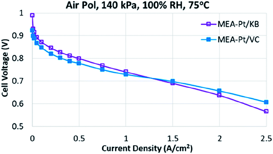 | ||
| Fig. 1 MEA performance for MEA-Pt/VC and MEA-Pt/KB at 100% RH, 75 °C, and 140 kPa. | ||
The electrochemical properties of the two catalysts are highlighted in Table 2. The XRF-measured Pt loadings are very close to the targeted Pt loading of 0.35 mg cm−2. It should be noted that while many publications have shown Pt loadings closer to 0.125 mg cm−2, the data here highlights that the differences in performance observed for these two carbon structures is not specific to ultralow loading designs, but rather, has immediate significance for current commercial products.
| Sample | Cathode loading (mg cm−2) | Roughness factor (cm2 Pt per cm2 MEA) | MEA ECSA (m2 g−1) | MEA mass activity (A mg−1) | RDE ECSA (m2 g−1) | RDE mass activity (A mg−1) |
|---|---|---|---|---|---|---|
| Pt/VC | 0.37 | 201 | 54 | 0.14 | 42 | 0.21 |
| Pt/KB | 0.36 | 202 | 56 | 0.24 | 48 | 0.18 |
At the RDE-level, both catalysts show very similar mass activities of ∼0.2 A mg−1 which is quite reasonable for a Pt/C catalyst.40 However, at the MEA-level there is a large discrepancy, with the Pt/VC catalyst showing nearly 2× lower mass activity vs. Pt/KB. This is not surprising, as it has been suggested that ionomer poisoning of the catalyst surface can decrease mass activity by a factor of >2.7 Thus, overall these results are fully in line with the expectations for these two catalysts, which serve as ideal model catalysts to determine whether a rapid ex situ method can be developed to screen ‘Pt accessibly’.
To evaluate the Pt accessibility in the catalyst layer, ECSA was measured as a function of relative humidity, with the results shown in Fig. 2. This approach has been used relatively widely in the literature,7,22 and consistently demonstrates relative ECSA vs. RH independence for ‘solid’ carbon supports, as is also shown here.
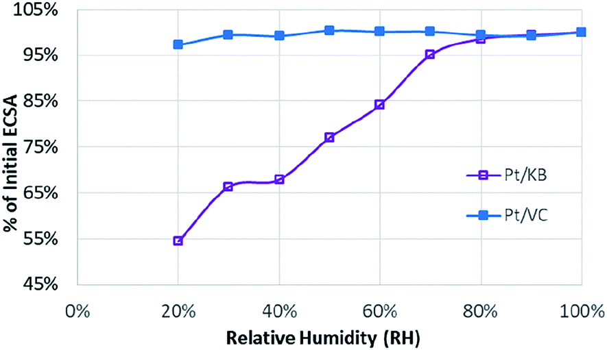 | ||
| Fig. 2 Relationship between ECSA and relative humidity for Pt/KB (purple) and Pt/VC (blue). | ||
The strong dependency of the roughness factor for catalysts such as Pt/KB on RH has previously been ascribed to the inability of protons to access the Pt particles housed inside the pores of mesoporous carbon materials.7,22,41 As the RH is decreased, the water pathways in the porous carbon structure are diminished leading to a loss of ECSA/roughness factor. For solid carbon supports such as Pt/VC, the majority of the Pt particles are located on the outer surface of the carbon and are thus far less sensitive to changes in RH as direct proton access through PFSA ionomer is possible. It should be noted that these observations on Pt distribution should be considered as statistical rather than 100% certain. In the case of Pt/KB, it is highly probable that some of the Pt particles reside on the outer surface of the carbon support, but a high percentage are likely housed in the pores.
Overall, Fig. 1 and 2 provide strong evidence that the Pt is primarily located on the outer surface of Pt/VC and within the pores of the carbon support for Pt/KB. To further verify this hypothesis, 3D TEM/TEM tomography was performed on both Pt/VC and Pt/KB (Fig. 3).
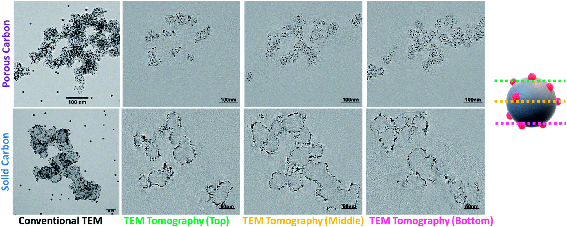 | ||
| Fig. 3 3D-TEM/TEM tomography images for Pt/KB and Pt/VC. | ||
The tomography images in Fig. 3 provide strong support for the proposed spatial distribution of Pt for both Pt/VC and Pt/KB. The full tomographic reconstruction and tilt series for these catalysts are available as ESI.† For Pt/VC, it is evident that nearly all of the Pt is constrained to the outer surface of the carbon structure, in good agreement with both the MEA data (Fig. 1 and 2) and previously reported TEM tomography on similar Pt/VC catalysts.8 For Pt/KB, it is clear that many of the Pt particles reside inside the carbon structure. It is generally accepted that ionomer cannot penetrate into the pores of KB,7,42,43 thus supporting the hypothesized reason for the MEA results shown in Fig. 1 and 2. Overall, with the MEA and TEM tomography results, it can be concluded that Pt/KB and Pt/VC are ideally suited to evaluate with the new ‘Pt accessibility’ method proposed in this work.
To determine Pt accessibility through RDE methods, the HUPD charge was measured as a function of sweep rate (Fig. S4†). For each catalyst, the HUPD charge was obtained using conventional methods.40 Briefly, the charge was calculated in the potential range of 0.05 to 0.37–0.4 V (the upper potential of the HUPD region was subjectively determined based on where the HUPD charge appeared to converge with the baseline charging current). The charging current was subtracted from the total charge within this potential range, and a value of 210 μC cm−2 was assumed for one monolayer of adsorbed hydrogen (Hads) on Pt.40 The electrochemical area was then divided by the mass of Pt on the electrode (45 μg cm−2 Pt) to obtain the ECSA. As shown in Fig. 4, the measured HUPD charge for both Pt/VC and Pt/KB decreases as the sweep rate increases. While Fig. S4† also shows that the CVs became resistive at high scan rates, the degree of CV distortion for both Pt/KB and Pt/VC were similar (Fig. S5†) suggesting that this observed resistance did not impact one of the catalysts more than the other.
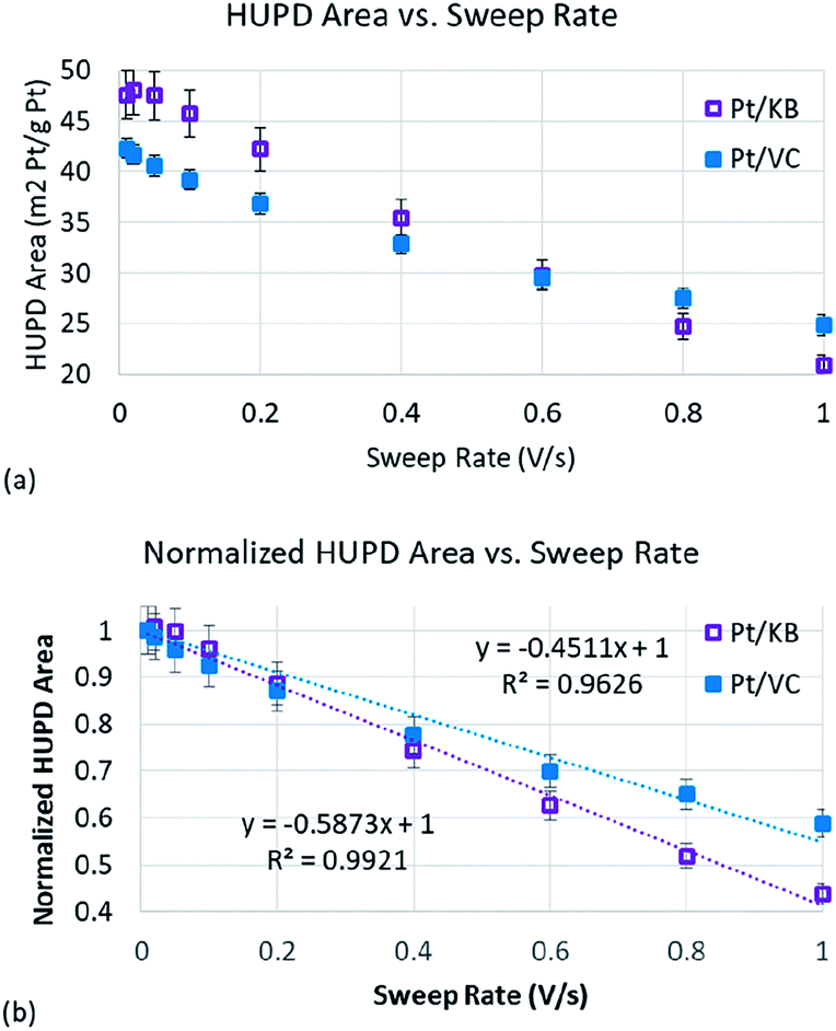 | ||
| Fig. 4 (a) The relationship between the HUPD area of Pt and the CV sweeping speed obtained by the RDE method; (b) the relationship between normalized Pt HUPD area and CV sweeping speed, and the inserted formulas are the results after curve fitting. | ||
Plotting changes in double layer charge vs. sweep rate has previously been used when studying carbon materials for use as supercapacitors.32,33 The double layer charge of more accessible carbon structures (larger pore diameter) is less sensitive to sweep rate as the ions are more easily able to transport in/out of the carbon pores at high rates. The same appears to be true for the HUPD process being plotted in Fig. 4(a). The HUPD area of the Pt/KB catalyst is initially higher than that of Pt/VC which has also been reported by other authors when comparing KB and VC supports.44 However, it is clear that the HUPD charge of Pt/VC is less strongly correlated to sweep rate than Pt/KB, such that at sweep rates of >600 mV s−1, the HUPD area of Pt/VC is actually measured to be higher than that of Pt/KB. To more clearly compare these two catalysts, the HUPD charges for both catalysts were normalized to their initial value measured at 10 mV s−1 (Fig. 4(b)). The slope of the best fit line in Fig. 4(b) is representative of the Pt accessibility, with Pt/KB showing a 30% higher slope vs. Pt/VC, indicative of the less accessible Pt in Pt/KB vs. Pt/VC. It is clear that this approach can already be used as a quick method to screen relative differences in ‘accessible’ vs. ‘inaccessible’ Pt, and can thus provide material scientists with a rapid and inexpensive approach to study Pt accessibility. Further development of this method should enable even stronger predictive capabilities, but the work here is sufficient for ‘proof of concept’ that this technique can be used. Specifically, the use of CO-stripping (as opposed to the HUPD method used here) may help to further improve the resolution in Fig. 4 as the signal to noise ratio is generally better for CO-stripping vs. the HUPD method.
In this work, we report a simple and inexpensive approach to help materials scientists rapidly evaluate the Pt accessibility of their Pt/C catalysts. Until now, the only tools for such analysis were MEA-level studies (including performance testing and/or plotting roughness factor vs. RH) or TEM tomography. While powerful techniques, both approaches are very expensive, time consuming, and not accessible to the majority of materials scientists researching new catalyst materials for PEMFCs. The simple method shown here requires only mg quantities of catalyst, and can be performed in several hours using relatively (vs. MEA test stations or 3D TEM tomography) inexpensive equipment that is accessible to nearly all materials scientists. While applied here for Pt/C catalysts, a similar technique could be used for non-precious metal catalysts (NPMCs) where active site accessibility is equally important. Since direct measurement of NPMC active sites is non-trivial, in this case the specific capacitance of the NPMC could be taken as estimate of ECSA and plotted vs. sweep rate.
Author contributions
Ye Peng: methodology, investigation, writing – original draft. Ja-Yeon Choi: methodology, visualization, investigation. Tobias Fürstenhaupt: methodology, visualization, investigation. Kyoung Bai: methodology, investigation. Yi Zhang and Dustin Banham: conceptualization, writing – review & editing, formal analysis, and supervision.Conflicts of interest
There are no conflicts to declare.Acknowledgements
We acknowledge the financial support from High-Level Talents of Guangdong Yangfan Program (Grant No. 201534032), Tip-top Scientific and Technical Innovative Youth Talents of Guangdong Special Support Program (Grant No. 201427033), the Innovation Team of Universities of Guangdong Province (2020KCXTD011), the Engineering Research Center of Universities of Guangdong Province (2019GCZX002), the Guangdong Key Laboratory for Hydrogen Energy Technologies (2018B030322005).Notes and references
- T. A. Greszler, D. Caulk and P. Sinha, J. Electrochem. Soc., 2012, 159, F831 CrossRef CAS
.
- K. Sakai, K. Sato, T. Mashio, A. Ohma, K. Yamaguchi and K. Shinohara, ECS Trans., 2009, 25, 1193 CrossRef CAS
- A. Kongkanand and M. Mathias, J. Phys. Chem. Lett., 2016, 7, 1127 CrossRef CAS PubMed
- N. Nonoyama, S. Okazaki, A. Z. Weber, Y. Ikogi and T. Yoshida, J. Electrochem. Soc., 2011, 158, B416 CrossRef CAS
- M. K. Debe, J. Electrochem. Soc., 2011, 159, B53 CrossRef
- D. Banham, J. Zou, S. Mukerjee, Z. Liu, D. Yang, Y. Zhang, Y. Peng and A. Dong, J. Power Sources, 2021, 490, 229515 CrossRef CAS
- V. Yarlagadda, M. K. Carpenter, T. E. Moylan, R. S. Kukreja, R. Koestner, W. Gu, L. Thompson and A. Kongkanand, ACS Energy Lett., 2018, 3, 618 CrossRef CAS
- D. Banham, F. Feng, T. Fürstenhaupt, K. Pei, S. Ye and V. Birss, J. Power Sources, 2011, 196, 5438 CrossRef CAS
- H. Jinnai, R. J. Spontak and T. Nishi, Macromolecules, 2010, 43, 1675 CrossRef CAS
- J. Zeng, D. I. Jean, C. Ji and S. Zou, Langmuir, 2012, 28, 957 CrossRef CAS PubMed
- K. Shinozaki, Y. Morimoto, B. S. Pivovar and S. S. Kocha, J. Power Sources, 2016, 325, 745 CrossRef CAS
- T. Masuda, F. Sonsudin, P. R. Singh, H. Naohara and K. Uosaki, J. Phys. Chem. C, 2013, 117, 15704 CrossRef CAS
- C. M. Zalitis, A. R. Kucernak, J. Sharman and E. Wright, J. Mater. Chem. A, 2017, 5, 23328 RSC
- N. Markovic, H. Gasteiger and P. N. Ross, J. Electrochem. Soc., 1997, 144, 1591 CrossRef CAS
- S.-I. Choi, M. Shao, N. Lu, A. Ruditskiy, H.-C. Peng, J. Park, S. Guerrero, J. Wang, M. J. Kim and Y. Xia, ACS Nano, 2014, 8, 10363 CrossRef CAS PubMed
- S.-I. Choi, S. Xie, M. Shao, J. H. Odell, N. Lu, H.-C. Peng, L. Protsailo, S. Guerrero, J. Park, X. Xia, J. Wang, M. J. Kim and Y. Xia, Nano Lett., 2013, 13, 3420 CrossRef CAS PubMed
- C. Chen, Y. Kang, Z. Huo, Z. Zhu, W. Huang, H. L. Xin, J. D. Snyder, D. Li, J. A. Herron, M. Mavrikakis, M. Chi, K. L. More, Y. Li, N. M. Markovic, G. A. Somorjai, P. Yang and V. R. Stamenkovic, Science, 2014, 343, 1339 CrossRef CAS PubMed
- T. Ito, U. Matsuwaki, Y. Otsuka, M. Hatta, K. Hayakawa, K. Matsutani, T. Tada and H. Jinnai, Electrochemistry, 2011, 79, 374 CrossRef CAS
- D. Banham, F. Feng, K. Pei, S. Ye and V. Birss, J. Mater. Chem. A, 2013, 1, 2812 RSC
- D. Banham, F. Feng, T. Furstenhaupt, S. Ye and V. Birss, J. Mater. Chem., 2012, 22, 7164 RSC
- S. Thiele, T. Fürstenhaupt, D. Banham, T. Hutzenlaub, V. Birss, C. Ziegler and R. Zengerle, J. Power Sources, 2013, 228, 185 CrossRef CAS
- S. Ott, A. Orfanidi, H. Schmies, B. Anke, H. N. Nong, J. Hubner, U. Gernert, M. Gliech, M. Lerch and P. Strasser, Nat. Mater., 2020, 19, 77 CrossRef CAS PubMed
- V. Yarlagadda, S. E. McKinney, C. L. Keary, L. Thompson, B. Zulevi and A. Kongkanand, J. Electrochem. Soc., 2017, 164, F845 CrossRef CAS
- D. Banham and S. Ye, ACS Energy Lett., 2017, 2, 629 CrossRef CAS
- X. Tian, X. F. Lu, B. Y. Xia and X. W. Lou, Joule, 2020, 4, 45 CrossRef CAS
- S. S. Kocha, K. Shinozaki, J. W. Zack, D. J. Myers, N. N. Kariuki, T. Nowicki, V. Stamenkovic, Y. Kang, D. Li and D. Papageorgopoulos, Electrocatalysis, 2017, 8, 366 CrossRef CAS
- K. Shinozaki, J. W. Zack, R. M. Richards, B. S. Pivovar and S. S. Kocha, J. Electrochem. Soc., 2015, 162, F1144 CrossRef CAS
- K. Shinozaki, J. W. Zack, S. Pylypenko, B. S. Pivovar and S. S. Kocha, J. Electrochem. Soc., 2015, 162, F1384 CrossRef CAS
- L. Pan, S. Ott, F. Dionigi and P. Strasser, Curr. Opin. Electrochem., 2019, 18, 61 CrossRef CAS
- S. Martens, L. Asen, G. Ercolano, F. Dionigi, C. Zalitis, A. Hawkins, A. Martinez Bonastre, L. Seidl, A. C. Knoll, J. Sharman, P. Strasser, D. Jones and O. Schneider, J. Power Sources, 2018, 392, 274 CrossRef CAS
- A. Riese, D. Banham, S. Ye and X. Sun, J. Electrochem. Soc., 2015, 162, F783 CrossRef CAS
- W. Xing, S. Z. Qiao, R. G. Ding, F. Li, G. Q. Lu, Z. F. Yan and H. M. Cheng, Carbon, 2006, 44, 216 CrossRef CAS
- D. Banham, F. Feng, J. Burt, E. Alsrayheen and V. Birss, Carbon, 2010, 48, 1056 CrossRef CAS
- Z. Li and M. Jaroniec, Chem. Mater., 2003, 15, 1327 CrossRef CAS
- W. Li, M. Waje, Z. Chen, P. Larsen and Y. Yan, Carbon, 2010, 48, 995 CrossRef CAS
- J. Speder, L. Altmann, M. Baumer, J. J. K. Kirkensgaard, K. Mortensen and M. Arenz, RSC Adv., 2014, 4, 14971 RSC
- P. J. Ferreira, G. J. La O', Y. Shao-Horn, D. Morgan, R. Makharia, S. Kocha and H. A. Gasteiger, J. Electrochem. Soc., 2005, 152, A2256 CrossRef
- T. Soboleva, X. Zhao, K. Malek, Z. Xie, T. Navessin and S. Holdcroft, ACS Appl. Mater. Interfaces, 2010, 2, 375 CrossRef CAS PubMed
- Y.-C. Park, H. Tokiwa, K. Kakinuma, M. Watanabe and M. Uchida, J. Power Sources, 2016, 315, 179 CrossRef CAS
- H. A. Gasteiger, S. S. Kocha, B. Sompalli and F. T. Wagner, Appl. Catal., B, 2005, 56, 9 CrossRef CAS
- Y. Li, T. Van Cleve, R. Sun, R. Gawas, G. Wang, M. Tang, Y. A. Elabd, J. Snyder and K. C. Neyerlin, ACS Energy Lett., 2020, 5, 1726 CrossRef CAS
- H. Iden and A. Ohma, J. Electroanal. Chem., 2013, 693, 34 CrossRef CAS
- G. S. Harzer, A. Orfanidi, H. El-Sayed, P. Madkikar and H. A. Gasteiger, J. Electrochem. Soc., 2018, 165, F770 CrossRef CAS
- Y. Liu, C. Ji, W. Gu, J. Jorne and H. A. Gasteiger, J. Electrochem. Soc., 2011, 158, B614 CrossRef CAS
Footnote |
| † Electronic supplementary information (ESI) available: Synthesis and characterization details. See DOI: 10.1039/d1ta01769a |
| This journal is © The Royal Society of Chemistry 2021 |