
 Open Access Article
 This Open Access Article is licensed under a Creative Commons Attribution-Non Commercial 3.0 Unported Licence
Computational design of a switchable heterostructure electrocatalyst based on a two-dimensional ferroelectric In2Se3 material for the hydrogen evolution reaction†
Han Seul
Kim
 *ab
*ab
aCentre for Supercomputing Applications, National Institute of Supercomputing and Networking, Korea Institute of Science and Technology Information (KISTI), Daejeon 34141, Republic of Korea. E-mail: hanseulkim0@kisti.re.kr
bDepartment of Data & High Performance Computing Science, University of Science & Technology (UST), Daejeon 34113, Republic of Korea
First published on 10th May 2021
Abstract
A theoretical design for an ON–OFF switchable HER catalyst using the two-dimensional ferroelectric (2D-FE) III2VI3 compound In2Se3 is reported in this paper. With vertical stacking of the basal plane of In2Se3 on top of the transition metal cobalt, a set of ab initio calculations reveals that the reversible polarization switching of In2Se3 can turn the HER activity of the heterostructure ON and OFF. The principle of HER activation/deactivation of the heterostructure is discussed in terms of the electronic structures, and the polarization-dependent modulation of electronic energy and charge transfer between In2Se3 and the transition metal are identified as the key factors. The distinct electron transfer mechanisms for the structures based on mono- and bilayers of In2Se3 are identified in terms of the different electronic connections between Co and In2Se3, and the structures are labelled as “direct” and “indirect” catalysts, respectively. This work provides insight into a possible pathway for designing dynamically controlled electrocatalysts based on 2D materials without introducing any chemical disorder.
Introduction
Recent years have witnessed an exploding interest and fast development in two-dimensional ferroelectric materials (2D-FEs).1,2 2D-FEs have reversible polarization that can be manipulated by external stimuli, even within their extremely thin atomic structures. Among many such materials, a class of two-dimensional III2VI3 compounds,3,4 which is one subgroup of the two-dimensional transition metal chalcogenides (2D-TMCs), is of particular interest. Various ferroelectric two-dimensional III2VI3 compounds with quintuple-layer (five-atom-thick) structures have recently been proposed through simulations, of which In2Se3 has been the most actively studied example of 2D-FE III2VI3 for the last few years in both theoretical and experimental works. After the theoretical estimations on the presence of in-plane and out-of-plane ferroelectricity in ground-state α-phase In2Se3,5,6 such ferroelectric behaviour was also observed experimentally.7–9 Owing to the interesting reversible polarization switching that can be enabled by applying an electric field, various applications such as ferroelectric memory10,11 and gas sensing12 have been suggested. To expedite the practical applications of In2Se3, advances such as large-area and ultrafast synthesis have also been pursued.13One compelling yet barely explored application of 2D-FE In2Se3 is as an electrocatalyst for which the simplest version is the hydrogen evolution reaction (HER) catalyst. Notably, recent computational studies have brilliantly demonstrated that In2Se3 shows reversible gas capture/release based on its polarization switching12 and exhibits adequate built-in potential for photocatalyst applications.14,15 This implies that In2Se3 can be utilized as an on/off reversible (photo-)catalyst after further manipulation of the molecular binding energies. Then, design of 2D-FE-based electrocatalyst structures with enhanced molecular adsorption and appropriate reaction energies by explicitly assessing the catalytic reaction should be the next step. In line with active researches on switchable catalysts using bulk ferroelectric materials,16,17 the investigation of possible approaches for the utilisation of 2D-FE In2Se3 as a switchable electrocatalyst is a highly promising research direction. In fact, stimuli-controlled and on–off switchable electrocatalysis for on-demand hydrogen production is particularly important for efficient hydrogen generation in portable devices.18–21 Furthermore, creative applications using on–off switchable electrocatalysts such as multiple stimuli-switchable electrocatalysis and logic gates have also been demonstrated.22
Meanwhile, the semiconducting nature and weak molecular adsorption of the basal plane have been pointed out as the main obstacles in the use of 2D-TMCs as electrocatalysts. It is a well-known design rule that the adsorption energy of catalytic intermediates on the catalytic surface should be moderate (not too high or too low).23,24 Therefore, boosting the molecular adsorption on the 2D-TMC surface is critical for effective utilisation of the large surface area and capability of atomic/electronic tuning25–27 of 2D-TMCs for electrocatalyst applications. Researchers have focused on modifying the atomic/electronic structures of 2D-TMCs to enhance molecular adsorption by exposing edges and introducing atomic defects and metastable metallic phases.28–34 Constructing heterointerfaces of 2D materials with metal substrates can be a more general approach for the systematic design of 2D-based HER catalysts without introducing chemical treatments.27,35
This work presents the computational design of an ON–OFF switchable HER catalyst with systematic tuning of the hydrogen adsorption energy by constructing vertical heterostructures based on 2D-FE III2VI3 In2Se3 and the transition metal cobalt. Cobalt is chosen because it is a non-precious transition metal with ferromagnetic properties. Brief results with reactive and inert diamagnetic metals, Cu and Au, will also be provided for comparison. Adopting a set of density functional theory (DFT) calculations, the effect of the ferroelectric polarity of In2Se3 on hydrogen adsorption will be first discussed based on the electronic structures. Then, the construction of Co + In2Se3 vertical heterostructures will be suggested as a powerful approach to amplify the effect of polarity to modulate HER efficiency. In these heterostructures, the HER activity can be turned on and off by ferroelectrically switching the polarity of In2Se3. The principles behind the relationship between the polarity and HER activity will be provided in view of electronic hybridizations between Co and In2Se3 and manipulation of the electronic states of In2Se3. The distinct origins of the HER activities for Co + In2Se3 complexes with mono- and bilayer In2Se3 will also be thoroughly discussed in terms of the electron transfer mechanisms. By devising a 2D-FE In2Se3 heterostructure for a switchable HER catalyst, this work will pave the way for the future design of dynamically controlled electrocatalysts using III2VI3 and other 2D ferroelectric materials.
Computational methods
Model preparation
The ground state of the ferroelectric α-In2Se3 has two degenerate phases, namely ferroelectric zincblende (FE-ZB′) and wurtzite (FE-WZ′) (ESI Fig. S1†). Among the two phases, FE-ZB′ was chosen to study the HER activities as in a previous report.6 According to the ferroelectric polarization (P) direction of In2Se3, which is defined by the location of the central Se atom (Sec), upward (U) and downward (D) polarizations models were defined (Fig. 1a). The 3 × 3 supercells of FE-ZB′ were prepared to adsorb H atoms to ensure that the distance between the H atoms in the neighbouring cells was larger than 12 Å. Thus, the effect of the adsorption density was ignored in this study. Meanwhile, a four-layer hexagonal close-packed (HCP) Co metal slab along the basal (0001) plane was prepared. Then, a 5 × 5 supercell Co was generated and scaled to the 3 × 3 supercell of In2Se3 FE-ZB′ to construct a vertical heterostructure. The lattice misfit between 5 × 5 Co and 3 × 3 In2Se3 was only 1%. The details are provided in Fig. S2.† | ||
| Fig. 1 (a) The atomic structures of monolayer FE-ZB′ In2Se3 with upward (U) and downward (D) out-of-plane polarizations. Top views (top) and side views (bottom) visualize how the positional shift of the Sec results in unique polarization switching. Ses indicates the surface Se atoms that will become active sites when adsorbing H*. The yellow and green shaded areas represent the InSe and InSe2, which are the substructures of In2Se3, respectively. d = 7.024 Å and P indicate the separation between the two In2Se3 layers and the polarization direction, respectively. (b) The projected density of states (PDOS) for U and D. The black lines and cyan-coloured areas indicate the p-orbital states of Sec and Ses, respectively. The orange arrow highlights the remarkable upshift of Ses states due to the position change of Sec. The red downward triangles indicate the position of the p-band peak for Ses (εp-peak). (c) The calculated free energies of hydrogen adsorption (ΔGH*) for different ferroelectric polarizations: U, D, and a nonpolarized phase (NP; face-centred cubic In2Se3, as shown in Fig. S1†). Sea indicates an active Ses atom where the H* is attached. (d) PDOS for the hydrogen-adsorbed U and D. The blue- and magenta-coloured areas are the p-orbital states of Sea and s-orbital state of H*, respectively. The red arrows indicate the electronic states of Ses that contribute to bond formations with H*. | ||
Electronic structure calculations
All of the DFT simulations were performed to calculate the total energies and vibrational frequencies within the grid-based projector-augmented wave method as implemented in the GPAW package.36 The revised Perdew–Burke–Ernzerhof (RPBE) functional was adopted as the exchange–correlation functional,37 and the wavefunctions were expanded on a real space grid with a grid spacing of 0.14 Å. Fermi smearing of 0.1 eV was used, and the calculations were performed on the periodically repeated unit cells and 3 × 3 supercells of In2Se3 with 8 × 8 × 1 and 2 × 2 × 1 Monkhorst–Pack Brillouin zone sampling, respectively. Spin polarization was considered for all calculations. As an eigensolver, the residual minimization method–direct inversion in iterative subspace (RMM–DIIS) was utilized.38,39 All of the structures were optimized using the conjugate-gradient method until the maximum force on any unconstrained atom was less than 0.05 eV Å−1. A vacuum space of 18 Å was adopted after a series of test calculations (Fig. S3†) to avoid artificial interactions between periodic images, and the dipole correction was applied to describe the properties of the slab accurately. The effects of the calculation parameters such as the self-consistent-field convergence criterion and force-convergence criterion were thoroughly tested, and the parameters that give cost-effective yet accurate estimations on ΔGH* were adopted for the data generation. The details are provided in Table S1.†Free energy calculations
ΔGH* is a reliable descriptor for HER activity under acidic conditions.23,24 The free energies of the atomic hydrogen adsorptions were calculated to evaluate the HER activity as:| ΔGH* = ΔEH* + ΔEZPE − TΔSH* | (1) |
| ΔEH* = Esub + H − (Esub + 1/2EH2), | (2) |
The free energy corrections (ΔEZPE and TΔSH*) were defined as:
| ΔEZPE = EZPE,1L + H* − (EZPE,1L + 0.5 × EZPE,H2), | (3) |
| ΔSH* = S1L + H* − (S1L + 0.5 × SH2), | (4) |
The EZPE was computed by summing the vibrational frequencies over all of the normal modes νi,
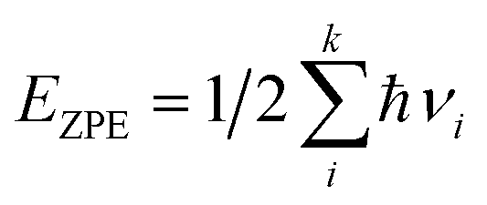 | (5) |
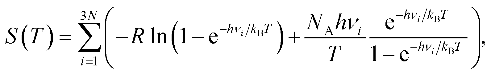 | (6) |
However, it is important to explicitly calculate all of the relevant terms because the catalytic activities of In2Se3 have not been studied previously. Therefore, all of the stationary modes of monolayer In2Se3 (1L) with and without adsorbed hydrogen were examined in this study using eqn (3)–(6). The vibrational density of states (VDOS) for 1L, 1L + H*, and gaseous H2 was obtained from the separate calculations without fixing any of the atoms. The details are summarized in Fig. S4 and Table S2† by showing the VDOS of 1L with/without adsorbed hydrogen and gas-phase hydrogens, and the energy correction is obtained as ΔEZPE − TΔSH* = − 0.0091 + 0.0359 = 0.0268 eV. Interestingly, the infinitesimal ΔEZPE indicates that the hydrogen adsorbed on selenium (4p) is relatively stable compared to that on carbon (2p, 0.17 eV).45
Results and discussion
HER activities of monolayer In2Se3: an indication of ferroelectricity-enabled HER control
Fig. 1a shows the atomic structures of the 1L FE-ZB′ α-In2Se3 with U and D polarization states. The U/D states of the polarization are achieved simply by shifting the vertical position of the Sec atom down/up by external stimuli such as the electric field. The Se atom on the top surface is marked as Ses and its position remains unchanged during polarization switching. Based on its quintuple-layer structure, the structure of In2Se3 can be further divided into two substructures, InSe and InSe2, as indicated in Fig. 1a by the yellow and green shaded areas, respectively. Accordingly, switching from U and D modifies the configuration of In2Se3 from “InSe2 (bottom) + InSe (top)” to “InSe (bottom) + InSe2 (top)”. A step-by-step procedure of the ferroelectric switching of FE-ZB′ In2Se3 and the corresponding energy barrier diagram are provided in ESI Fig. S5.†Polarization switching significantly modifies the projected density of states (PDOS) of FE-ZB′, as depicted in Fig. 1b. Unlike for transition metal catalysts, the p-orbital states of the active surface play the key role in HER on 2D-TMC.46–48 In particular, the proximity of the valence band (VB) contribution of the Ses p-states (the filled p-orbitals) to the Fermi energy (EF) is of central importance. More specifically, the energetic location of the pz-state is worth considering because the electrons should be transferred from the In2Se3 surface to adsorbed hydrogen by forming the bonding between Se 4pz and H 1s to activate HER as shown in Fig. S6 and S7.†49 To quantify the details for the location of the pz-states of Ses, the 4pz-band centre (εpz-centre) can be introduced. εpz-centre represents the energetic location of the centre of 4pz-states, analogous to the well-known d-centre:49–51
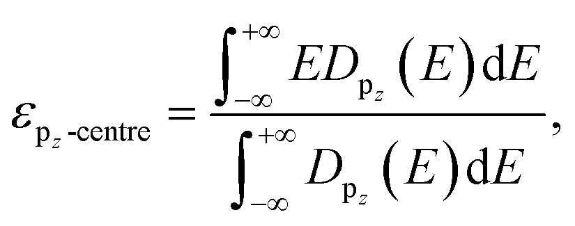 | (7) |
While the PDOS of Sec remains unchanged, the εpz-centre/εp-centre of Ses is −2.86/−3.26 eV in U and −1.67/−2.03 eV in D, which is an indication of a significant peak shift of ∼1.60 eV during polarization switching. This means that the electronic states of Sec hybridize/dehybridize with those of Ses by forming InSe2/InSe, depending on the position in D/U. Therefore, the atomic movement of Sec in D/U effectively turns ON/OFF the near-EF contribution of the filled Ses p-states, while the electronic state of Sec itself is unchanged. Note that the spin-polarization was considered in the calculations and only the α-spin component is presented in the PDOS plot after checking that there is no significant difference between the PDOS of the two spin components.
It should be highlighted that the built-in potential within In2Se3 takes a key role in the polarization-dependent switching of the εpz-centre. The intrinsic dipole directs from the InSe2 to InSe substructure within the In2Se3, as can be seen from the bond dipoles (BDs) between the two substructures (Fig. S8†). The H* adsorption on In2Se3 induces a negative bond dipole, which reduces/amplifies the dipole moment of 1L(D)/1L(U) (Fig. S8†). Correspondingly, the location of εpz-centre (and εp-centre) with respect to EF is manipulated due to the polarization-dependent built-in potential (Fig. S9†). This means that the polarization-dependent local bonding environment of In2Se3 plays an essential role in modulating hydrogen adsorption while the built-in electric field plays a supporting role, as previously reported for a Janus MoSSe monolayer.52
Owing to the manipulated locations of the filled Ses p-states, the simple reversal of the polarization direction from U to D remarkably reduces the free energies of hydrogen adsorption (ΔGH*) by more than 1.0 eV, from 1.74 eV to 0.71 eV (Fig. 1c). The ΔGH* for models U and D are obtained using eqn (1) by attaching hydrogen (H*) onto one of the Ses atoms (an active Se; Sea) in the 3 × 3 supercells of monolayer In2Se3 (ESI Fig. S10†). The H*–Sea bond formation on U at the InSe substructure is highly endothermic and accompanied by noticeable surface distortions. Correspondingly, the entire downward shift of the filled p-state (indicated by the red arrows) is observed upon H adsorption (Fig. 1d). On the other hand, D undergoes only a negligible surface distortion upon H adsorption on the InSe2 substructure, and only the local valence band maximum – 1 (VBM-1) peak of p-Ses at EF − 2.49 eV shifts downward in Sea (denoted by a red arrow in Fig. 1d) upon Se–H bond formation.
Note that, unfortunately, ΔGH* is still too large in both the U and D cases for an isolated In2Se3 to become a suitable HER catalyst. Similar to other 2D-TMCs,53,54 the hydrogen adsorption will be too weak on isolated In2Se3. More thorough investigations into the relationship between the ferroelectric polarization and ΔGH* is provided in ESI Fig. S11.†D favours HER better than U, while HER is not activated in all cases even with the bilayer In2Se3 (2L), as will be shown in the later part of this paper.
The “direct” switchable catalyst: a case with Co + a monolayer of In2Se3
To exploit the polarization-dependent modulation of ΔGH* for turning the HER activity on and off, H* adsorption on In2Se3 should be amplified. Constructing vertical heterostructures with metal substrates is one effective approach in this regard, as in the cases of other 2D materials.27,35 As a metal substrate, the transition metal Co is employed in this work. The ferromagnetism of Co can be pointed out as a key factor in ‘turning on’ the HER of In2Se3 upon heterostructuring, by breaking the spin degeneracy of In2Se3 so that its electronic states move toward EF (Fig. S12†). By contrast, HER is not activated when adopting diamagnetic metals such as Au and Cu (Fig. S13†). Details of the metal species-dependency can be provided in the following work, and this study will focus on the design of an ON–OFF switchable HER catalyst using a Co metal slab.By stacking monolayer In2Se3 on top of Co (Co + 1L), the strong effect of Co converts the electronic structure of 1L to be more favourable for H* adsorption. Fig. 2a and b respectively show the charge density differences (CDDs) of Co + 1L(D) and Co + 1L(D) + H*. The CDD of 1L vertically stacked on a Co metal slab is defined as:
| ΔρCo + 1L = ρCo + 1L − (ρCo + ρ1L) | (8) |
| Δρ[Co + 1L] + H* = ρ[Co + 1L] + H* − (ρCo +1L + ρH), | (9) |
 | ||
| Fig. 2 Charge density differences and PDOS plots for (a) Co + 1L(D), (b) Co + 1L(D) + H*, (c) Co + 1L(U), and (d) Co + 1L(U) + H*. The green and yellow shaded areas indicate InSe2 and InSe substructures within In2Se3, respectively. The isovalue is 0.001 e Å−3, while the yellow and cyan colours represent positive and negative values, respectively. The cyan, black, and blue areas in the PDOS indicate the p-orbital states of Ses, Sec, and Sei, respectively. The brown shaded areas and orange dashed lines indicate the d-orbital states of Coi and Cob, respectively. The red and orange downward triangles indicate the position of the p-band peaks for Ses (εp-peak) and Sec, respectively. | ||
The corresponding PDOS plots shown on the right hand sides of Fig. 2a–d more closely reveal the origin of the catalytic activities. Since the ferromagnetic properties of Co induce the spin splitting of In2Se3 (Fig. S12†), α and β spins are shown in the positive and negative DOS regions, respectively. The Se atoms at the Co–In2Se3 interface (Sei) strongly hybridize with the interface Co atoms (Coi), both for Co + 1L(U) and Co + 1L(D) (Fig. 2a and c). Furthermore, Sec and Ses become slightly metallic owing to having a finite value in the bandgap region of In2Se3 (Fig. S12 and S14†). Having a synergistic effect with strain caused by chemical bonding, this promotes charge transfer from the electron reservoir Co to the In2Se3 active surface. This is consistent with the recent studies demonstrating that the synergistic effects of local bonding and charge transfer related to surface states can tune the adsorption properties of the surfaces.55,56 Such adjustments of the surface adsorption characteristics can even control the growth modes of the thin film and the stability of the catalyst.
Meanwhile, the intrinsic built-in potential of In2Se3 (Fig. S15†) polarization-dependently modifies the potential energies of the active surface when adsorbed on Co. Therefore, the occupied p-orbital states of Sec in Co + 1L(D) are located near EF, while those of Co + 1L(U) are located far below EF (the orange downward triangles in Fig. 2a and c). Recalling that the Co + 1L(U) can be divided into Co–InSe2 and InSe, while Co + 1L(D) consists of Co–InSe and InSe2, Sec is selectively hybridized with Ses/Sei for Co + 1L(U)/Co + 1L(U). Thus, the filled p-Ses state in Co + 1L(U) is located even further away, while it comes closer to EF and coincides with that of Sec in Co + 1L(D) (marked by the red downward triangles). Correspondingly, the εpz-centre/εp-centre of Ses is −3.15/−3.58 eV in Co + 1L(U), and the values significantly shift closer to zero (EF) in Co + 1L(D) by having −1.58/−1.97 eV. The values are given for the α-spin state that is located closer to EF than its β-spin counterpart.
The upward shift of εpz-centre/εp-centre assists the electron transfer from Co to In2Se3 in Co + 1L(D) and this promotes H* adsorption through the hybridization of the Sea-p and H-s orbitals (Fig. 2b and d). Eventually, polarization switching turns HER activity “ON” and “OFF”, by showing ΔGH* for Co+1L(D) = 0.079 eV < 0.2 eV, while having ΔGH* for Co+1L(U) = 0.49 eV > 0.2 eV. Note that the ΔGH* values are provided after finding an active site among various Ses (Fig. S16†). Each Ses gives a slightly different ΔGH* due to the difference in the local structures but shows ΔGH* < 0.2 eV for Co + 1L(D) in all cases. Because the Co metal slab directly modulates the activity of the In2Se3 based on strong chemical bonding, Co + 1L(D) can be categorized as a “direct catalyst”.
The “indirect” switchable catalyst: a case with Co + a bilayer of In2Se3
The effect of the Co substrate can be further investigated by stacking one more In2Se3 on top of Co + 1L, creating Co + 2L. Since Co + 1L(D) has been identified as an effective metal in the previous section, it is informative to consider Co + 2L(D) as a composite of an active layer 1L(D) and an effective metallic substrate Co + 1L(D). Fig. 3a illustrates the CDD between the substrate Co + 1L(D) and the active material 1L(D), where Δρ[Co + 1L] + 1L is obtained using eqn (8) but replacing Co with Co + 1L. Due to the introduction of the Co substrate, the CDD between the two 1L(D)s in Co + 2L(D) is significantly amplified compared to the case of 2L(D) without Co (Fig. S17†). Correspondingly, the physical interlayer distance (d) between the 1L layers was noticeably reduced by 0.5 Å from 3.93 Å to 3.43 Å when introducing Co (Fig. 3a and S17†). Furthermore, the excess charge (the red arrow) is observed at the top of Ses within the Co + 2L(D), and this will act again as a ‘glue’ for assisting hydrogen attachment (Fig. 3a). On the contrary, the charge deficiency (the blue arrow) shown at the top of Ses for Co + 2L(U) implies that the hydrogen adsorption will be less favoured (Fig. 3c).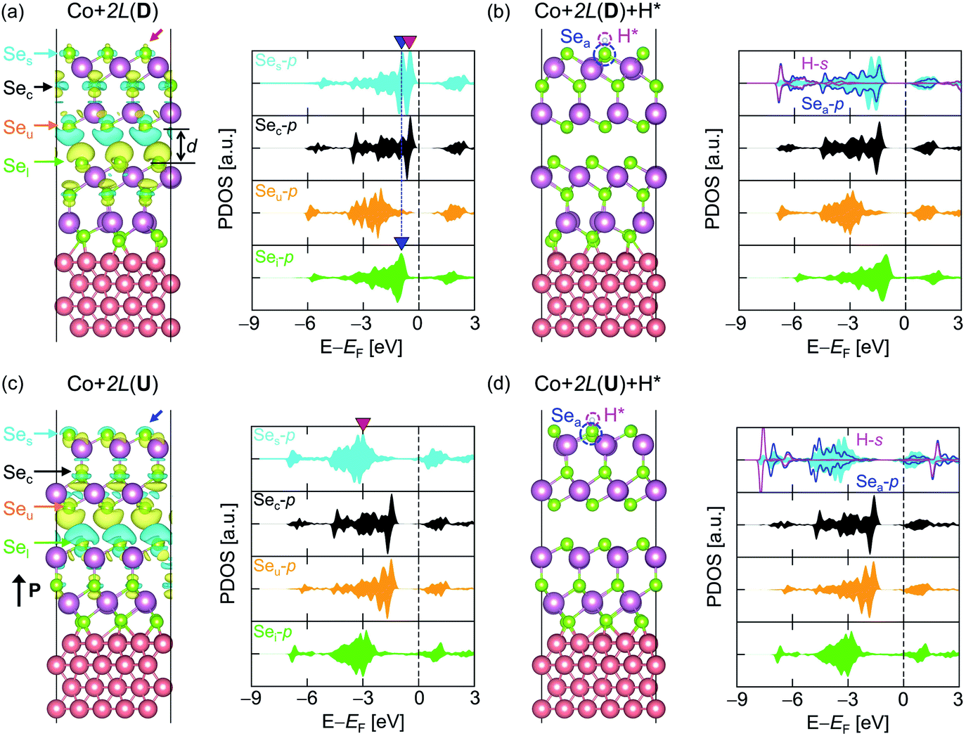 | ||
| Fig. 3 Atomic models (left) and the PDOS (right) for (a) Co + 2L(D), (b) Co + 2L(D) + H*, (c) Co + 2L(U), and (d) Co + 2L(U) + H*. For the models without H*, CDDs between the two In2Se3 layers are overlaid with the atomic models. The isovalue is 0.0002 e/Å3, while the yellow and cyan colours represent positive (excessive electrons) and negative (deficient electrons) values, respectively. d = 3.43 Å indicates an interlayer distance between the 1L layers within Co + 2L(D). Red/blue arrows indicate the excessive/deficient charge at the active surface of Co + 2L(D)/Co + 2L(U). The types of atoms in the models are indicated by coloured arrows, and the same colours are used to represent the PDOS: cyan, black, orange, green, blue, and magenta represent Ses, Sec, Seu, Sel, Sea, and H*, respectively. In plotting the PDOS, p-orbitals for Se and s-orbitals for H are used. The blue downward triangles indicate the energy location of the local VBM-1 for Ses and Sel. The red downward triangle represents the position of the p-band peak for Ses (εp-peak). | ||
Focusing on PDOS, the local VBM-1 p-states of the outer surface atoms in the lower (Sel) and upper (Ses) In2Se3 layers coincide entirely in terms of electronic energy, as indicated by the blue downward triangles. Due to the charge transfer between Co and the first In2Se3, the electron tunnelling channel opens up across the two In2Se3 layers. Then, a well-connected electron transport channel near EF evolves from the substrate to the active layer, efficiently supplying electrons for the HER. Note that the effect of the Co substrate is now weaker than that in the above-mentioned Co + 1L case and the induced metallicity and strain on the active surface are absent.
ε pz-centre/εp-centre for Co + 2L(D) is −1.28/−1.62 eV and ΔGH* is obtained as 0.111 eV in the “HER-ON” state. Such channel-opening results from the charge transfer between Co and In2Se3, which is not observed in 2L(D) (Fig. S17†). The corresponding potential energy profiles are provided in Fig. S18.† When a hydrogen is attached, the electronic state of the upper In2Se3 layer (Ses, Sec, and Seu) shifts downward, while that of the lower In2Se3 layer (Sel) remains unchanged (Fig. 3b). With the hydrogen desorption, the tunnelling channel from the Co to the top 1L(D) opens up again (Fig. 3a). The electron tunnelling channel in Co + 2L(U) is similarly connected from Co + 1L(U) to the top 1L(U) but the filled p-Ses states are located far below EF (Fig. 3c and d). εpz-centre/εp-centre is −3.33/−3.75 eV for Co + 2L(U) with ΔGH* = 1.665 eV in “HER-OFF”. Thus, ON/OFF switchable HER is again achieved with Co + 2L. Since the Co metal slab indirectly modulates the activity of the In2Se3 based on weak physisorption (the van der Waals interaction between the two In2Se3 without induced metallicity and strain) and tunnelling, Co + 2L(D) is labelled as an “indirect catalyst”.
The descriptors for HER-ON/OFF states
Fig. 4a provides a schematic diagram that summarizes the HER activities of the models introduced throughout this work and Fig. 4b and c visualize the evaluations of the ON/OFF states for HER based on ΔGH*. Prior to their incorporation in the heterostructure, monolayer In2Se3, bilayer In2Se3, and the bare metal Co are all inactive materials for HER. Upon stacking monolayer In2Se3 on top of Co (Fig. 4b), the ΔGH* of Co + 1L(U) and Co + 1L(D) is 0.49 eV (>0.20 eV) and 0.082 eV (<0.20 eV), respectively. This identifies Co + 1L(U) as “HER-OFF” and Co + 1L(D) as “HER-ON” states. Therefore, the HER activities of 1L stacked on Co can be turned “ON” and “OFF” simply by controlling its polarity to D and U using external stimuli. Furthermore, the switchable HER activity can be observed even when stacking bilayer In2Se3 on the Co slab (Fig. 4c). After adsorbing one more In2Se3 layer on top of Co + 1L through van der Waals interactions, Co + 2L(D) and Co + 2L(U) are also respectively assigned as “HER-ON” and “HER-OFF”. The ΔGH* values of Co + 2L(D) and Co + 2L(U) are 0.11 eV < 0.20 eV and 1.67 eV > 0.20 eV, respectively. | ||
| Fig. 4 (a) A schematic diagram of HER based on In2Se3 FE-ZB′ and Co. First, neither Co nor 1L is a suitable HER catalyst for opposite reasons: while hydrogens adsorb too strongly on a bare Co metal surface, they are unlikely to adsorb on an isolated In2Se3 regardless of the polarity (U or D). Second, Co metal surfaces that are decorated by D state-In2Se3 of either 1L or 2L are good HER catalysts. The atomic-level origin for these HER activities is distinct for monolayer and bilayer In2Se3, which are identified as “direct” and “indirect”, respectively. A free energy diagram for HER at zero potential on various Co–In2Se3 heterostructures with (b) 1L and (c) 2L. The red, blue, green, magenta, and black lines indicate 1L/2L(U), 1L/2L(D), Co + 1L/2L(U), Co + 1L/2L(D), and bare Co cases, respectively. The grey shaded area indicates the condition where |ΔGH*| < 0.20 eV. | ||
The origins of ON–OFF switching can be systematically analysed based on Table 1, providing the ΔGH* and ON/OFF status of the models in Fig. 4 with proper descriptors. First, the effect of ferroelectric switching is indicated by εpz-centre and εp-centre. For all of the models, the values are closer to zero (the filled p-Ses are closer to EF) in D than U and modulating the structure from U to D significantly reduces ΔGH*. Since U and D in each model are basically the same material with different ferroelectric states, εpz-centre, εp-centre, and εp-peak are intuitive descriptors for comparing the HER efficiencies of U and D. However, εpz-centre/εp-centre/εp-peak cannot be the only parameters for HER efficiency when it comes to the comparison of two distinct materials since the evaluation of HER efficiency basically contains the precise assessment of hydrogen adsorption energies. For example, as the stiffness or stability of In2Se3 changes with the thickness, the hydrogen adsorption energy will also change with the number of In2Se3 layers. While 2L(D) shows a higher εs and smaller ΔGH* than its 1L(D) counterpart, the assessment of thickness-dependent HER activity cannot be discussed simply on the basis of εpz-centre/εp-centre/εp-peak when the In2Se3 becomes thicker.
| Model | P | ΔGH* [eV] | ON/OFFa | ε pz-centre (α/β) [eV] | ε p-centre (α/β) [eV] | ε p-peak (α/β) [eV] | Co effectb |
|---|---|---|---|---|---|---|---|
| a ‘ON’ if |ΔGH*| < 0.20 eV, ‘OFF’ if not. b ‘Strong’ if the active In2Se3 is directly attached on Co, ‘weak’ if the active In2Se3 is influenced by but not directly attached to Co, ‘None’ if there is no Co in the atomic model. | |||||||
| Co + 1L | D | 0.082 | ON | −1.58/−1.78 | −1.97/−2.16 | −0.91/−1.14 | Strong |
| U | 0.490 | OFF | −3.15/−3.32 | −3.58/−3.64 | −3.17/−3.27 | ||
| Co + 2L | D | 0.111 | ON | −1.28/−1.45 | −1.62/−1.79 | −0.47/−0.65 | Weak |
| U | 1.665 | OFF | −3.33/−3.48 | −3.75/−3.91 | −3.00/−3.19 | ||
| 1L | D | 0.710 | OFF | −1.67 | −2.03 | −0.87 | None |
| U | 1.740 | −2.86 | −3.26 | −2.48 | |||
| 2L | D | 0.448 | −1.35 | −1.71 | −0.55 | ||
| U | 1.745 | −3.23 | −3.63 | −2.85 | |||
Meanwhile, the Co metal slab significantly modifies the electronic structure of In2Se3. Co acts as an electron reservoir and provides an electron transfer channel to activate In2Se3. This is particularly enabled by the ferromagnetism of Co because Co-induced spin decomposition on In2Se3 attracts α spin to shift closer to EF as a major charge transfer channel. If In2Se3 undergoes the ‘strong’ Co effect, the nature of In2Se3 will be modified through applied strain and slight metallization due to the Co–In2Se3 hybridizations. Even if the In2Se3 undergoes only a ‘weak’ Co effect, the electrons will be efficiently supplied to the active surface while the electronic structure of In2Se3 remains intact.
Achieving ON and OFF states of HER can be understood as manipulating the synergy of the ferroelectric switching of In2Se3 and the ferromagnetic Co effects. In the absence of Co (few-layer In2Se3 with no Co effect), ΔGH* for D is always more favourable for HER than its U counterpart as can be anticipated in the previous report12 but always stays “OFF” for all cases. When Co is introduced without metalizing In2Se3 or hybridizations (Co + 2L with a ‘weak’ Co effect), the electrons are transferred to the active surface through tunnelling to promote hydrogen adsorption. ΔGH* is reduced both in D and U so that the ON(D)–OFF(U) states of HER are achieved. Co + 2L(D) has been labelled as an ‘indirect’ catalyst in this paper. For ‘strong’ Co effects with interfacial strain, induced metallicity, and hybridizations on In2Se3 (Co + 1L), ΔGH* is further reduced by direct charge transfer. Then, ON(D)–OFF(U) states of HER are again achieved. Having a ΔGH* of almost zero, Co + 1L(D) can be understood as a more efficient catalyst than Co + 2L(D) and labelled as a ‘direct’ catalyst.
Conclusions
In summary, this theoretical work provides a brief concept design and insight into the construction of a dynamic catalyst based on a 2D-FE material-transition metal complex. The main points in this work can be summarized as follows:• A theoretical design of a 2D material-based heterostructure for a switchable catalyst.
• A theoretical formulation on how the ferroelectric modulation of the 2D material gives rise to an active/inactive HER surface through coupling with a non-noble metal substrate, without introducing chemical modifications.
Owing to the unique quintuple structure and intrinsic ferroelectricity of the III2VI3 compound, the stacking of In2Se3 onto the ferromagnetic transition metal Co slab enables control over the hydrogen adsorption onto In2Se3, thereby switching the HER on and off. The underlying principle is the polarization-dependent control of the electron supply from Co to In2Se3, which is based on the synergy of ferroelectric switching of In2Se3 and the effect of ferromagnetic metal Co. Correspondingly, the “direct” and “indirect” catalysts are defined in terms of the bonding nature of the electron supply paths from Co to In2Se3 (either chemical bonding at Co + 1L In2Se3 or tunnelling through physical bonding at Co + 2L In2Se3).
For the design of switchable electrocatalysts based on 2D-FE III2VI3 heterostructures, this work mainly focuses on the principles of catalytic activities of the heterostructure through theoretical discussions by taking In2Se3 as an example III2VI3 material. For the viability of ON–OFF conversion, the controllability of the polarization energy barrier of In2Se3 in response to external stimuli without (Fig. S19†) and with (Fig. S20 and S21†) the presence of a Co slab was also briefly investigated. The energy barrier for D–U conversion in a neutral system implies the reasonable stability of the structure. The barrier can be significantly reduced by applying an electric field or net charge. It is important to recall that a switchable non-volatile memory based on the polarization conversion of few-layer In2Se3 (∼2.6 nm) was realized experimentally by applying a gate bias on top of a metallic gate.10 Consistent with the experimental achievement, the backgate voltage that gives the net charge on the system can modulate the energy barrier between D and U even when the In2Se3 is adsorbed on the Co substrate (Fig. S20 and S21†). While brief indications of the viability of the ON–OFF conversion are provided, the next step will be to theoretically expand and experimentally realize this brief idea. Thorough theoretical discussions on the thickness-dependent ΔGH* of ferroelectric In2Se3, metal species-dependent HER activity of the metal-In2Se3 heterostructure and ON–OFF conversion dynamics within the non-equilibrium external stimuli will be pursued in the following studies. In this effort, the design principle and theoretical analysis provided in this work will offer key guidances for the experimental development of switchable electrocatalysts based on 2D-FE III2VI3 heterostructures in the future.
Conflicts of interest
There are no conflicts to declare.Acknowledgements
All the simulation data in this work were generated and analysed with the active use of the NURION (KISTI-5) high-performance computing resources supported by the Korea Institute of Science and Technology Information (KISTI) (KSC-2019-CRE-0199 & KSC-2020-CRE-0300). This work was carried out under the financial support from the institutional R&D program of KISTI (K-21-L02-C10) and the National R&D program of the National Research Foundation (NRF) (NRF-2020R1F1A1075573) funded by the Ministry of Science and ICT of Korea. I would like to thank my dear friend Min Jong Noh for all of the support and valuable discussions regarding this research.Notes and references
- C. Cui, F. Xue, W. J. Hu and L. J. Li, npj 2D Mater. Appl., 2018, 2, 18 CrossRef.
- Z. Guan, H. Hu, X. Shen, P. Xiang, N. Zhong, J. Chu and C. Duan, Adv. Electron. Mater., 2020, 6, 1–30 Search PubMed.
- W. Xiong, K. Huang and S. Yuan, J. Mater. Chem. C, 2019, 7, 13518–13525 RSC.
- H. Li, S. Hu, S. Zhao and C. Lan, Chem. Phys. Lett., 2020, 749, 137404 CrossRef CAS.
- L. Debbichi, O. Eriksson and S. Lebègue, J. Phys. Chem. Lett., 2015, 6, 3098–3103 CrossRef CAS PubMed.
- W. Ding, J. Zhu, Z. Wang, Y. Gao, D. Xiao, Y. Gu, Z. Zhang and W. Zhu, Nat. Commun., 2017, 8, 14956 CrossRef CAS PubMed.
- Y. Zhou, D. Wu, Y. Zhu, Y. Cho, Q. He, X. Yang, K. Herrera, Z. Chu, Y. Han, M. C. Downer, H. Peng and K. Lai, Nano Lett., 2017, 17, 5508–5513 CrossRef CAS PubMed.
- S. Li, J. Z. Liu, M. T. Edmonds, L. Yu, J. L. Collins, Y. Lou, C. Xu, C. Zheng, Z. Wei, M. S. Fuhrer, D. Kim, J. Seidel, Y. Zhang, W.-X. Tang, Y. Zhu, M. Li and L. Zhu, Sci. Adv., 2018, 4, eaar7720 CrossRef PubMed.
- C. Cui, W. Hu, X. Yan, C. Addiego, W. Gao, Y. Wang, Z. Wang, L. Li, Y. Cheng, P. Li, X. Zhang, H. N. Alshareef, T. Wu, W. Zhu, X. Pan and L.-J. Li, Nano Lett., 2018, 18, 1253–1258 CrossRef CAS PubMed.
- S. Wan, Y. Li, W. Li, X. Mao, C. Wang, C. Chen, J. Dong, A. Nie, J. Xiang, Z. Liu, W. Zhu and H. Zeng, Adv. Funct. Mater., 2019, 29, 1808606 CrossRef.
- P. Hou, S. Xing, X. Liu, C. Chen, X. Zhong, J. Wang and X. Ouyang, RSC Adv., 2019, 9, 30565–30569 RSC.
- X. Tang, J. Shang, Y. Gu, A. Du and L. Kou, J. Mater. Chem. A, 2020, 8, 7331–7338 RSC.
- H. Shi, M. Li, A. Shaygan Nia, M. Wang, S. Park, Z. Zhang, M. R. Lohe, S. Yang and X. Feng, Adv. Mater., 2020, 32, 1907244 CrossRef CAS PubMed.
- C. F. Fu, J. Sun, Q. Luo, X. Li, W. Hu and J. Yang, Nano Lett., 2018, 18, 6312–6317 CrossRef CAS PubMed.
- P. Zhao, Y. Ma, X. Lv, M. Li, B. Huang and Y. Dai, Nano Energy, 2018, 51, 533–538 CrossRef CAS.
- A. Kakekhani, S. Ismail-Beigi and E. I. Altman, Surf. Sci., 2016, 650, 302–316 CrossRef CAS.
- Y. Zhang, M. Xie, V. Adamaki, H. Khanbareh and C. R. Bowen, Chem. Soc. Rev., 2017, 46, 7757–7786 RSC.
- L. Cui, Y. Xu, L. Niu, W. Yang and J. Liu, Nano Res., 2017, 10, 595–604 CrossRef CAS.
- F. Erogbogbo, T. Lin, P. M. Tucciarone, K. M. Lajoie, L. Lai, G. D. Patki, P. N. Prasad and M. T. Swihart, Nano Lett., 2013, 13, 451–456 CrossRef CAS PubMed.
- S. Hao, L. Yang, L. Cui, W. Lu, Y. Yang, X. Sun and A. M. Asiri, Nanotechnology, 2016, 27, 46 Search PubMed.
- Y. Sofue, K. Nomura and A. Inagaki, Chem. Commun., 2020, 56, 4519–4522 RSC.
- Y. Ma, M. Li, K. Shi, Z. Chen, B. Yang, D. Rao, X. Li, W. Ma, S. Hou, G. Gou and H. Yao, New J. Chem., 2020, 44, 16045–16053 RSC.
- P. Sabatier, Ber. Dtsch. Chem. Ges., 1911, 44, 1984–2001 CrossRef CAS.
- J. K. Nørskov, T. Bligaard, A. Logadottir, J. R. Kitchin, J. G. Chen, S. Pandelov and U. Stimming, J. Electrochem. Soc., 2005, 152, J23–J26 CrossRef.
- D. Deng, K. S. Novoselov, Q. Fu, N. Zheng, Z. Tian and X. Bao, Nat. Nanotechnol., 2016, 11, 218–230 CrossRef CAS PubMed.
- C. Wang, J. Huang, J. Chen, Z. Xi and X. Deng, Front. Chem., 2019, 7, 131 CrossRef CAS PubMed.
- X. Long, W. Qiu, Z. Wang, Y. Wang and S. Yang, Mater. Today Chem., 2019, 11, 16–28 CrossRef CAS.
- P. Raybaud, J. Hafner, G. Kresse, S. Kasztelan and H. Toulhoat, J. Catal., 2000, 189, 129–146 CrossRef CAS.
- B. Hinnemann, P. G. Moses, J. Bonde, K. P. Jørgensen, J. H. Nielsen, S. Horch, I. Chorkendorff and J. K. Nørskov, J. Am. Chem. Soc., 2005, 127, 5308–5309 CrossRef CAS PubMed.
- H. Wang, Z. Lu, S. Xu, D. Kong, J. J. Cha, G. Zheng, P. C. Hsu, K. Yan, D. Bradshaw, F. B. Prinz and Y. Cui, Proc. Natl. Acad. Sci. U. S. A., 2013, 110, 19701–19706 CrossRef CAS PubMed.
- M. A. Lukowski, A. S. Daniel, F. Meng, A. Forticaux, L. Li and S. Jin, J. Am. Chem. Soc., 2013, 135, 10274–10277 CrossRef CAS PubMed.
- X. Huang, Z. Zeng and H. Zhang, Chem. Soc. Rev., 2013, 42, 1934–1946 RSC.
- Q. Tang and D. E. Jiang, ACS Catal., 2016, 6, 4953–4961 CrossRef CAS.
- J. Zhu, Z. C. Wang, H. Dai, Q. Wang, R. Yang, H. Yu, M. Liao, J. Zhang, W. Chen, Z. Wei, N. Li, L. Du, D. Shi, W. Wang, L. Zhang, Y. Jiang and G. Zhang, Nat. Commun., 2019, 10, 1348 CrossRef PubMed.
- G. Zhao, K. Rui, S. X. Dou and W. Sun, Adv. Funct. Mater., 2018, 28, 1803291 CrossRef.
- J. J. Mortensen, L. B. Hansen and K. W. Jacobsen, Phys. Rev. B: Condens. Matter Mater. Phys., 2005, 71, 035109 CrossRef.
- B. Hammer, L. B. Hansen and J. K. Nørskov, Phys. Rev. B: Condens. Matter Mater. Phys., 1999, 59, 7413–7421 CrossRef.
- E. L. Briggs, D. J. Sullivan and J. Bernholc, Phys. Rev. B: Condens. Matter Mater. Phys., 1995, 52, R5471–R5474 CrossRef CAS PubMed.
- G. Kresse and J. Furthmüller, Phys. Rev. B: Condens. Matter Mater. Phys., 1996, 54, 11169–11186 CrossRef CAS PubMed.
- N. M. Marković, B. N. Grgur and P. N. Ross, J. Phys. Chem. B, 1997, 101, 5405–5413 CrossRef.
- A. Hjorth Larsen, J. Jørgen Mortensen, J. Blomqvist, I. E. Castelli, R. Christensen, M. Dułak, J. Friis, M. N. Groves, B. Hammer, C. Hargus, E. D. Hermes, P. C. Jennings, P. Bjerre Jensen, J. Kermode, J. R. Kitchin, E. Leonhard Kolsbjerg, J. Kubal, K. Kaasbjerg, S. Lysgaard, J. Bergmann Maronsson, T. Maxson, T. Olsen, L. Pastewka, A. Peterson, C. Rostgaard, J. Schiøtz, O. Schütt, M. Strange, K. S. Thygesen, T. Vegge, L. Vilhelmsen, M. Walter, Z. Zeng and K. W. Jacobsen, J. Phys.: Condens. Matter, 2017, 29, 273002 CrossRef PubMed.
- R. P. Stoffel, C. Wessel, M.-W. Lumey and R. Dronskowski, Angew. Chem., Int. Ed., 2010, 49, 5242–5266 CrossRef CAS PubMed.
- A. Togo and I. Tanaka, Scr. Mater., 2015, 108, 1–5 CrossRef CAS.
- Y. A. Zhu, D. Chen, X. G. Zhou and W. K. Yuan, Catal. Today, 2009, 148, 260–267 CrossRef CAS.
- J. Deng, P. Ren, D. Deng and X. Bao, Angew. Chem., Int. Ed., 2015, 54, 2100–2104 CrossRef CAS PubMed.
- Y. Jiao, Y. Zheng, K. Davey and S. Z. Qiao, Nat. Energy, 2016, 1, 16130 CrossRef CAS.
- H. Shu, D. Zhou, F. Li, D. Cao and X. Chen, ACS Appl. Mater. Interfaces, 2017, 9, 42688–42698 CrossRef CAS PubMed.
- Y. Zhang, X. Chen, Y. Huang, C. Zhang, F. Li and H. Shu, J. Phys. Chem. C, 2017, 121, 1530–1536 CrossRef CAS.
- Y. Cui, M. Li, X. Zhang, S. Wang and Y. Huang, Green Energy Environ. DOI:10.1016/j.gee.2021.01.002.
- B. Hammer and J. K. Norskov, Nature, 1995, 376, 238–240 CrossRef CAS.
- J. K. Nørskov, F. Abild-Pedersen, F. Studt and T. Bligaard, Proc. Natl. Acad. Sci. U.S.A., 2011, 108, 937–943 CrossRef PubMed.
- C. Jin, X. Tang, X. Tan, S. C. Smith, Y. Dai and L. Kou, J. Mater. Chem. A, 2019, 7, 1099–1106 RSC.
- Y. Jiao, Y. Zheng, M. Jaroniec and S. Z. Qiao, Chem. Soc. Rev., 2015, 44, 2060–2086 RSC.
- Z. W. Chen, L. X. Chen, Z. Wen and Q. Jiang, Phys. Chem. Chem. Phys., 2019, 21, 23782–23802 RSC.
- Z. Su, R. Pang, X. Ren and S. Li, J. Mater. Chem. A, 2020, 8, 17238–17247 RSC.
- L. Zhang, W. Qin, L. Li, S. Li, P. Cui, Y. Jia and Z. Zhang, Nanoscale, 2018, 10, 18988–18994 RSC.
Footnote |
| † Electronic supplementary information (ESI) available. See DOI: 10.1039/d0ta09738a |
| This journal is © The Royal Society of Chemistry 2021 |